CN1288771C - Polymer electrolytic fuel battery - Google Patents
Polymer electrolytic fuel battery Download PDFInfo
- Publication number
- CN1288771C CN1288771C CNB2004100304662A CN200410030466A CN1288771C CN 1288771 C CN1288771 C CN 1288771C CN B2004100304662 A CNB2004100304662 A CN B2004100304662A CN 200410030466 A CN200410030466 A CN 200410030466A CN 1288771 C CN1288771 C CN 1288771C
- Authority
- CN
- China
- Prior art keywords
- anode
- seal
- total pore
- polymer electrolyte
- cathode side
- Prior art date
- Legal status (The legal status is an assumption and is not a legal conclusion. Google has not performed a legal analysis and makes no representation as to the accuracy of the status listed.)
- Expired - Fee Related
Links
- 239000000446 fuel Substances 0.000 title claims abstract description 139
- 229920000642 polymer Polymers 0.000 title 1
- 238000007789 sealing Methods 0.000 claims abstract description 155
- 239000005518 polymer electrolyte Substances 0.000 claims abstract description 110
- 239000007789 gas Substances 0.000 claims description 262
- 239000011148 porous material Substances 0.000 claims description 199
- 239000007800 oxidant agent Substances 0.000 claims description 91
- 230000001590 oxidative effect Effects 0.000 claims description 89
- 239000002737 fuel gas Substances 0.000 claims description 77
- 229920001971 elastomer Polymers 0.000 claims description 9
- 230000000712 assembly Effects 0.000 claims description 8
- 238000000429 assembly Methods 0.000 claims description 8
- 229920001940 conductive polymer Polymers 0.000 claims description 8
- GPRLSGONYQIRFK-UHFFFAOYSA-N hydron Chemical compound [H+] GPRLSGONYQIRFK-UHFFFAOYSA-N 0.000 claims description 8
- 229920005989 resin Polymers 0.000 claims description 6
- 239000011347 resin Substances 0.000 claims description 6
- 239000003795 chemical substances by application Substances 0.000 claims description 2
- 230000003647 oxidation Effects 0.000 claims description 2
- 238000007254 oxidation reaction Methods 0.000 claims description 2
- 230000006835 compression Effects 0.000 claims 1
- 238000007906 compression Methods 0.000 claims 1
- 239000012528 membrane Substances 0.000 abstract description 17
- 210000004027 cell Anatomy 0.000 description 133
- 239000010408 film Substances 0.000 description 87
- 239000000498 cooling water Substances 0.000 description 42
- 238000009792 diffusion process Methods 0.000 description 30
- 238000000034 method Methods 0.000 description 23
- 230000003321 amplification Effects 0.000 description 17
- 238000003199 nucleic acid amplification method Methods 0.000 description 17
- XLYOFNOQVPJJNP-UHFFFAOYSA-N water Substances O XLYOFNOQVPJJNP-UHFFFAOYSA-N 0.000 description 15
- 239000003054 catalyst Substances 0.000 description 13
- 239000002131 composite material Substances 0.000 description 13
- 238000004519 manufacturing process Methods 0.000 description 12
- 230000008569 process Effects 0.000 description 12
- 238000001514 detection method Methods 0.000 description 11
- 238000011156 evaluation Methods 0.000 description 10
- 230000012447 hatching Effects 0.000 description 9
- BASFCYQUMIYNBI-UHFFFAOYSA-N platinum Chemical compound [Pt] BASFCYQUMIYNBI-UHFFFAOYSA-N 0.000 description 9
- 229920001721 polyimide Polymers 0.000 description 9
- 238000003825 pressing Methods 0.000 description 9
- OKTJSMMVPCPJKN-UHFFFAOYSA-N Carbon Chemical compound [C] OKTJSMMVPCPJKN-UHFFFAOYSA-N 0.000 description 8
- 229920005549 butyl rubber Polymers 0.000 description 8
- 230000008859 change Effects 0.000 description 8
- 230000000694 effects Effects 0.000 description 8
- UFHFLCQGNIYNRP-UHFFFAOYSA-N Hydrogen Chemical compound [H][H] UFHFLCQGNIYNRP-UHFFFAOYSA-N 0.000 description 7
- 230000015572 biosynthetic process Effects 0.000 description 7
- 239000007767 bonding agent Substances 0.000 description 7
- 239000012530 fluid Substances 0.000 description 7
- 239000001257 hydrogen Substances 0.000 description 7
- 229910052739 hydrogen Inorganic materials 0.000 description 7
- 238000012360 testing method Methods 0.000 description 7
- TXEYQDLBPFQVAA-UHFFFAOYSA-N tetrafluoromethane Chemical compound FC(F)(F)F TXEYQDLBPFQVAA-UHFFFAOYSA-N 0.000 description 7
- LSNNMFCWUKXFEE-UHFFFAOYSA-M Bisulfite Chemical compound OS([O-])=O LSNNMFCWUKXFEE-UHFFFAOYSA-M 0.000 description 6
- 238000007731 hot pressing Methods 0.000 description 5
- 238000009413 insulation Methods 0.000 description 5
- 239000000463 material Substances 0.000 description 5
- 238000012545 processing Methods 0.000 description 5
- IJGRMHOSHXDMSA-UHFFFAOYSA-N Atomic nitrogen Chemical compound N#N IJGRMHOSHXDMSA-UHFFFAOYSA-N 0.000 description 4
- 238000001816 cooling Methods 0.000 description 4
- 230000005611 electricity Effects 0.000 description 4
- 230000006870 function Effects 0.000 description 4
- 229910002804 graphite Inorganic materials 0.000 description 4
- 239000010439 graphite Substances 0.000 description 4
- 238000007689 inspection Methods 0.000 description 4
- 229910052697 platinum Inorganic materials 0.000 description 4
- 229920006254 polymer film Polymers 0.000 description 4
- 238000004080 punching Methods 0.000 description 4
- 229910001220 stainless steel Inorganic materials 0.000 description 4
- 239000010935 stainless steel Substances 0.000 description 4
- KFZMGEQAYNKOFK-UHFFFAOYSA-N Isopropanol Chemical compound CC(C)O KFZMGEQAYNKOFK-UHFFFAOYSA-N 0.000 description 3
- 229920002367 Polyisobutene Polymers 0.000 description 3
- 229920000800 acrylic rubber Polymers 0.000 description 3
- QVGXLLKOCUKJST-UHFFFAOYSA-N atomic oxygen Chemical compound [O] QVGXLLKOCUKJST-UHFFFAOYSA-N 0.000 description 3
- 230000004888 barrier function Effects 0.000 description 3
- 238000006243 chemical reaction Methods 0.000 description 3
- 238000004132 cross linking Methods 0.000 description 3
- 238000013461 design Methods 0.000 description 3
- 239000003792 electrolyte Substances 0.000 description 3
- 229920001973 fluoroelastomer Polymers 0.000 description 3
- 239000000203 mixture Substances 0.000 description 3
- 230000004048 modification Effects 0.000 description 3
- 238000012986 modification Methods 0.000 description 3
- 238000000465 moulding Methods 0.000 description 3
- 239000001301 oxygen Substances 0.000 description 3
- 229910052760 oxygen Inorganic materials 0.000 description 3
- 230000002093 peripheral effect Effects 0.000 description 3
- 229920000058 polyacrylate Polymers 0.000 description 3
- 238000007493 shaping process Methods 0.000 description 3
- 125000000391 vinyl group Chemical group [H]C([*])=C([H])[H] 0.000 description 3
- 229920002554 vinyl polymer Polymers 0.000 description 3
- 229920000049 Carbon (fiber) Polymers 0.000 description 2
- LFQSCWFLJHTTHZ-UHFFFAOYSA-N Ethanol Chemical compound CCO LFQSCWFLJHTTHZ-UHFFFAOYSA-N 0.000 description 2
- 239000004642 Polyimide Substances 0.000 description 2
- 239000004743 Polypropylene Substances 0.000 description 2
- 230000001154 acute effect Effects 0.000 description 2
- 230000002411 adverse Effects 0.000 description 2
- 239000003570 air Substances 0.000 description 2
- 239000004917 carbon fiber Substances 0.000 description 2
- 230000015556 catabolic process Effects 0.000 description 2
- 230000007423 decrease Effects 0.000 description 2
- 238000006731 degradation reaction Methods 0.000 description 2
- 238000001035 drying Methods 0.000 description 2
- 239000004744 fabric Substances 0.000 description 2
- 239000001307 helium Substances 0.000 description 2
- 229910052734 helium Inorganic materials 0.000 description 2
- SWQJXJOGLNCZEY-UHFFFAOYSA-N helium atom Chemical compound [He] SWQJXJOGLNCZEY-UHFFFAOYSA-N 0.000 description 2
- 238000001746 injection moulding Methods 0.000 description 2
- VNWKTOKETHGBQD-UHFFFAOYSA-N methane Chemical compound C VNWKTOKETHGBQD-UHFFFAOYSA-N 0.000 description 2
- 229910052757 nitrogen Inorganic materials 0.000 description 2
- 239000002245 particle Substances 0.000 description 2
- -1 polypropylene Polymers 0.000 description 2
- 229920001155 polypropylene Polymers 0.000 description 2
- 239000000843 powder Substances 0.000 description 2
- 238000007639 printing Methods 0.000 description 2
- 238000000926 separation method Methods 0.000 description 2
- 239000010409 thin film Substances 0.000 description 2
- 238000012546 transfer Methods 0.000 description 2
- 239000013585 weight reducing agent Substances 0.000 description 2
- RPAJSBKBKSSMLJ-DFWYDOINSA-N (2s)-2-aminopentanedioic acid;hydrochloride Chemical compound Cl.OC(=O)[C@@H](N)CCC(O)=O RPAJSBKBKSSMLJ-DFWYDOINSA-N 0.000 description 1
- 229920000181 Ethylene propylene rubber Polymers 0.000 description 1
- 239000006230 acetylene black Substances 0.000 description 1
- 230000009471 action Effects 0.000 description 1
- 238000004026 adhesive bonding Methods 0.000 description 1
- 238000004458 analytical method Methods 0.000 description 1
- 229910052799 carbon Inorganic materials 0.000 description 1
- 239000006229 carbon black Substances 0.000 description 1
- 230000019771 cognition Effects 0.000 description 1
- 238000000748 compression moulding Methods 0.000 description 1
- 239000004020 conductor Substances 0.000 description 1
- 238000010276 construction Methods 0.000 description 1
- 238000000354 decomposition reaction Methods 0.000 description 1
- 230000007812 deficiency Effects 0.000 description 1
- 238000007599 discharging Methods 0.000 description 1
- 238000006073 displacement reaction Methods 0.000 description 1
- 238000003487 electrochemical reaction Methods 0.000 description 1
- 239000002003 electrode paste Substances 0.000 description 1
- 238000003411 electrode reaction Methods 0.000 description 1
- 238000005516 engineering process Methods 0.000 description 1
- NBVXSUQYWXRMNV-UHFFFAOYSA-N fluoromethane Chemical compound FC NBVXSUQYWXRMNV-UHFFFAOYSA-N 0.000 description 1
- 230000008676 import Effects 0.000 description 1
- 238000009434 installation Methods 0.000 description 1
- 230000010354 integration Effects 0.000 description 1
- 230000014759 maintenance of location Effects 0.000 description 1
- 238000002156 mixing Methods 0.000 description 1
- 230000035699 permeability Effects 0.000 description 1
- 229920001195 polyisoprene Polymers 0.000 description 1
- 238000010248 power generation Methods 0.000 description 1
- 230000004044 response Effects 0.000 description 1
- 238000007650 screen-printing Methods 0.000 description 1
- 239000013464 silicone adhesive Substances 0.000 description 1
- 239000007787 solid Substances 0.000 description 1
- 230000008685 targeting Effects 0.000 description 1
Images


Classifications
-
- H—ELECTRICITY
- H01—ELECTRIC ELEMENTS
- H01M—PROCESSES OR MEANS, e.g. BATTERIES, FOR THE DIRECT CONVERSION OF CHEMICAL ENERGY INTO ELECTRICAL ENERGY
- H01M8/00—Fuel cells; Manufacture thereof
- H01M8/02—Details
- H01M8/0271—Sealing or supporting means around electrodes, matrices or membranes
- H01M8/0273—Sealing or supporting means around electrodes, matrices or membranes with sealing or supporting means in the form of a frame
-
- H—ELECTRICITY
- H01—ELECTRIC ELEMENTS
- H01M—PROCESSES OR MEANS, e.g. BATTERIES, FOR THE DIRECT CONVERSION OF CHEMICAL ENERGY INTO ELECTRICAL ENERGY
- H01M8/00—Fuel cells; Manufacture thereof
- H01M8/02—Details
- H01M8/0202—Collectors; Separators, e.g. bipolar separators; Interconnectors
- H01M8/0267—Collectors; Separators, e.g. bipolar separators; Interconnectors having heating or cooling means, e.g. heaters or coolant flow channels
-
- H—ELECTRICITY
- H01—ELECTRIC ELEMENTS
- H01M—PROCESSES OR MEANS, e.g. BATTERIES, FOR THE DIRECT CONVERSION OF CHEMICAL ENERGY INTO ELECTRICAL ENERGY
- H01M8/00—Fuel cells; Manufacture thereof
- H01M8/02—Details
- H01M8/0271—Sealing or supporting means around electrodes, matrices or membranes
- H01M8/0276—Sealing means characterised by their form
-
- H—ELECTRICITY
- H01—ELECTRIC ELEMENTS
- H01M—PROCESSES OR MEANS, e.g. BATTERIES, FOR THE DIRECT CONVERSION OF CHEMICAL ENERGY INTO ELECTRICAL ENERGY
- H01M8/00—Fuel cells; Manufacture thereof
- H01M8/10—Fuel cells with solid electrolytes
- H01M8/1004—Fuel cells with solid electrolytes characterised by membrane-electrode assemblies [MEA]
-
- H—ELECTRICITY
- H01—ELECTRIC ELEMENTS
- H01M—PROCESSES OR MEANS, e.g. BATTERIES, FOR THE DIRECT CONVERSION OF CHEMICAL ENERGY INTO ELECTRICAL ENERGY
- H01M8/00—Fuel cells; Manufacture thereof
- H01M8/24—Grouping of fuel cells, e.g. stacking of fuel cells
- H01M8/241—Grouping of fuel cells, e.g. stacking of fuel cells with solid or matrix-supported electrolytes
-
- H—ELECTRICITY
- H01—ELECTRIC ELEMENTS
- H01M—PROCESSES OR MEANS, e.g. BATTERIES, FOR THE DIRECT CONVERSION OF CHEMICAL ENERGY INTO ELECTRICAL ENERGY
- H01M8/00—Fuel cells; Manufacture thereof
- H01M8/24—Grouping of fuel cells, e.g. stacking of fuel cells
- H01M8/2457—Grouping of fuel cells, e.g. stacking of fuel cells with both reactants being gaseous or vaporised
-
- H—ELECTRICITY
- H01—ELECTRIC ELEMENTS
- H01M—PROCESSES OR MEANS, e.g. BATTERIES, FOR THE DIRECT CONVERSION OF CHEMICAL ENERGY INTO ELECTRICAL ENERGY
- H01M8/00—Fuel cells; Manufacture thereof
- H01M8/24—Grouping of fuel cells, e.g. stacking of fuel cells
- H01M8/2465—Details of groupings of fuel cells
- H01M8/2483—Details of groupings of fuel cells characterised by internal manifolds
-
- H—ELECTRICITY
- H01—ELECTRIC ELEMENTS
- H01M—PROCESSES OR MEANS, e.g. BATTERIES, FOR THE DIRECT CONVERSION OF CHEMICAL ENERGY INTO ELECTRICAL ENERGY
- H01M8/00—Fuel cells; Manufacture thereof
- H01M8/10—Fuel cells with solid electrolytes
- H01M8/1016—Fuel cells with solid electrolytes characterised by the electrolyte material
- H01M8/1018—Polymeric electrolyte materials
-
- Y—GENERAL TAGGING OF NEW TECHNOLOGICAL DEVELOPMENTS; GENERAL TAGGING OF CROSS-SECTIONAL TECHNOLOGIES SPANNING OVER SEVERAL SECTIONS OF THE IPC; TECHNICAL SUBJECTS COVERED BY FORMER USPC CROSS-REFERENCE ART COLLECTIONS [XRACs] AND DIGESTS
- Y02—TECHNOLOGIES OR APPLICATIONS FOR MITIGATION OR ADAPTATION AGAINST CLIMATE CHANGE
- Y02E—REDUCTION OF GREENHOUSE GAS [GHG] EMISSIONS, RELATED TO ENERGY GENERATION, TRANSMISSION OR DISTRIBUTION
- Y02E60/00—Enabling technologies; Technologies with a potential or indirect contribution to GHG emissions mitigation
- Y02E60/30—Hydrogen technology
- Y02E60/50—Fuel cells
Abstract
A highly reliable polymer electrolyte fuel cell is provided at low costs by using a sealing member that is compact and has excellent gas tightness. The polymer electrolyte fuel cell includes an anode-side separator plate and a cathode-side separator plate that are provided with an anode-side sealing member and a cathode-side sealing member, respectively. These anode-side and cathode-side sealing members seal the cell in cooperation with a polymer electrolyte membrane at sealing parts where the anode-side and cathode-side sealing members are opposed to each other, thereby preventing gas from leaking out of gas flow channels. One of the anode-side and cathode-side sealing members has a pointed rib that comes in contact with the sealing parts in a linear manner, and the other sealing member comes in contact with the sealing parts surface to surface.
Description
Technical field
The present invention relates to the polymer electrolyte fuel cells on the power supply that is used for compact power, electric automobile, domestic combined generating system or the similar device.
Background technology
Fuel cell that includes a polymer electrolyte film can be by making fuel gas that contains hydrogen and the oxidant gas that contains aerobic, for example air generation electrochemical reaction and produce electric energy and heat energy simultaneously.This fuel cell comprises that one can be carried hydrionic polymer electrolyte film and a pair of electrode (anode and negative electrode) that is formed on the polymer electrolyte film both sides selectively.These electrodes are formed on by a catalyst layer that is formed on the polymer electrolyte film both sides and one that lip-deep gas diffusion layers constitutes outside the catalyst layer.Catalyst layer mainly is made up of the powdered carbon that carries platinum metal catalysts, and gas diffusion layers has air permeability and good and electron conduction.
Have air seal material or the sealing ring that can clamp polymer electrolyte film around electrode, purpose is to prevent that the fuel gas and the oxidant gas that are supplied to from taking place to leak and prevent that it from mixing.Air seal material or sealing gasket are made into integration with electrode and polymer electrolyte film in advance.This fabricated structure is called electrolyte thin membrane-electrode assembly (MEA).
What be arranged on the MEA outside is a plurality of conductive separator plate, and these conductive separator plate are used for fixing MEA and adjacent MEA is cascaded.These dividing plates (or claim divider plate) have a gas flow channel, and this gas flow channel is used for supplying with active gases and the gas that produced and unnecessary gas being discharged to electrode surface.Although can being independent of dividing plate, this gas passage is provided with separately,, generally on the surface of dividing plate, be formed with a plurality of grooves, these grooves are used as gas flow channel.
For active gases (or claim reacting gas) is transported in these grooves, just need to adopt a pipe clamp, this pipe clamp can extend in the groove of corresponding dividing plate according to the quantity of the dividing plate tube furcation that carries out from active gases.This pipe clamp is called as " house steward ", and the service of active gases is called " outside house steward " in the above-mentioned house steward that the groove of corresponding dividing plate couples together.The better simply house steward of structure is called as " inner house steward ".Inner house steward comprises a plurality of through holes that are formed on the corresponding dividing plate, and has a plurality of gas flow channels on corresponding dividing plate.These through holes are connected with the entrance and exit of gas flow channel, so just can active gases directly be supplied to gas flow channel by these through holes.
Because fuel cell will produce heat in operating process, therefore just need cool off fuel cell with cooling water or analog, purpose is that fuel cell is remained under the good temperature conditions.Generally, each battery or per three batteries just have the cooling end section that an inner stream has cooling water.This cooling end section is provided with by the back side at dividing plate normally that a flow of cooling water passage forms.These MEA and dividing plate alternately are stacked, thereby form one by 10 to 200 assemblies that battery is formed, and a collector plate is connected with each end of battery pack with an insulation board.The final assembly that forms is sandwiched between between a plurality of end plates and utilizes fishbolt to be fixed together from two ends.The structure of Here it is conventional fuel battery.
The sealing gasket that is used on this polymer electrolyte fuel cells seals gas, allows dividing plate and electrode to be in contact with one another simultaneously, so just requires sealing gasket to have the accuracy to size of height, enough elasticity and enough amount of interference.For satisfying these requirements, prior art generally adopts the plate-shaped sealing gasket of being made by resin or rubber, or is encircled by the O shape that rubber is made.
In addition, in recent years, people attempt to reduce to act on the load on the sealing gasket always, and purpose is clamping load and the weight reduction that reduces battery pack, reduce the quantity of parts and reduce the manufacturing cost of parts.Wherein a kind of method just is: except O shape ring, also having adopted cross section is triangle or semiorbicular sealing gasket (for example, Japanese patent gazette 2002-141082).For ease of assembling, some other method attempts sealing gasket is installed on the dividing plate, rather than is installed to MEA upward (for example Japanese patent gazette 2002-231264).
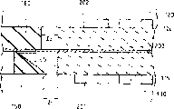
Figure 13 is near the longitudinal sectional view of O-ring seals of conventional fuel cell. O shape ring 236 and 246 is fitted in O shape circular groove groove 236a and the 246a, and these grooves are respectively formed on anode side baffle 210 and the cathode side separator 200.This O shape ring 236 is pressed against electrolytic thin-membrane 231 on the cathode side separator 220, and O shape ring 246 is pressed against electrolytic thin-membrane 231 on the anode side baffle 210.Like this, just can seal by 236 and 246 pairs of gases between electrolytic thin-membrane and anode side baffle and cathode side separator of O shape ring.On behalf of anode, Reference numeral 232b, Reference numeral 232a represent negative electrode, Reference numeral 212b to represent fuel gas flow passage and Reference numeral 223b to represent the oxidant gas flow passage.
Like this, because O shape sealing gasket is realized sealing on two positions, therefore the problem of this conventional seals method just is to take very big seal cavity.
In addition, for the dividing plate of the total cast in inside, air seal portion section extends to electrode part section (portion's section can be understood as part or parts in this manual) from this house steward, and electrolytic thin-membrane will be enough big like this, to cover in this house steward, will increase cost like this.In addition, along with the increase of diaphragm size, the processing to barrier film in assembling process is also difficult more, because the thickness of barrier film is about 25 to 50 microns (μ m).
On the other hand, when in order to reduce cost and to improve the property handled and intensity and when reducing the size of barrier film, just need have certain rigid protecting film and cover this electrolytic thin-membrane with a kind of.If an element cell comprises this small-sized electrolytic thin-membrane, the thickness of electrolytic thin-membrane can make electrode height on every side there are differences so, will occur the problem that sealing characteristics reduces like this.In addition, when above-mentioned O shape ring is used as sealing gasket, just need the expensive time assemble this O shape ring, because this O shape ring itself is very thin, and be not rigidity, in the assembling process of battery pack, can not therefore just make its manufacturing cost higher to reversing O-ring seals.
In addition, because dividing plate made by electric conducting material,, will between the dividing plate of MEA, clamping produce short circuit problem so if therefore in assembling process, there is the foreign matter of conduction.The distortion that produces when the warpage of dividing plate or distortion, assembling fuel cell etc. also may cause short circuit between dividing plate.In addition, if between fuel cell that assembles and heat insulating member, there is the conduction foreign matter, so also can cause short circuit.
In addition, when O shape ring was used to seal, fuel cell can for example be installed in a MEA on the dividing plate by its each stacked elements is finished assembling together, another dividing plate then is installed on it, a sealing gasket and another dividing plate perhaps are installed on it.In this assembling process, the sealing gasket or the dividing plate that need be installed on the MEA are installed along the pilot pin of assembling jig.But, because there are scale error in these elements, therefore just can not be successfully, effectively such element is assembled together, unless the gap between sealing gasket and the MEA is even as big as allowing the degree of these scale errors.Like this, active gases just can flow through in the final gap between sealing gasket and the electrode, thereby walks around the gas flow channel on the dividing plate.
Because MEA and the rigging error of sealing gasket and the existence of other factor, make the pressure loss in the units corresponding is changed different and different with each unit of gap length between electrode and the sealing gasket.Pressure loss variation in the units corresponding will cause the flow velocity of active gases to change, and be decided by the pressure loss that units corresponding is interior because active gases flows into the interior quantity of units corresponding of a fuel cell.Therefore, units corresponding just shows the variation on the performance, and the variation on the performance comprises some adverse influences, for example the following degradation of electromotive force, durability and low output function stability.These adverse effects are more obvious in anode-side, because the active gases that anode-side is used is more.
And, if want to reduce sealing gasket and gaps between electrodes, just need to improve corresponding size of component accuracy, will reduce output like this and increase the manufacturing cost of element.In addition, when the gap reduced, it is difficult that the assembling of respective element will become, and the reliability of assembling also can reduce.Therefore, will cause seal failure, for example because partial electrode has covered the sealing section; And tensile stress and shear stress also can too much act on the electrolytic thin-membrane, thereby causes degradation problem under electrolytic thin-membrane breakage, the durability.
In recent years, for improving the performance of battery, people require to improve the humidity of supply gas always.In oxidant gas side, produced water by reaction, these water should be discharged in electrode rapidly and stably.If sealing gasket and gaps between electrodes diminish, sealing gasket and gaps between electrodes have perhaps been eliminated substantially, purpose is to prevent detouring of active gases when adopting traditional sealing gasket, so water is discharged with regard to needing very big pressure in electrode, will reduce system effectiveness like this.In addition, the clamping force that reduces the sealing section also is the problem that needs solve, and purpose is weight reduction, reduce volume and reduce the cost of clamping part.In these cases, just need simple, effective seal structure.
Summary of the invention
The objective of the invention is to: provide a kind of good reliability, fuel cell that cost is low by adopting a kind of compact conformation, seal that air-tightness is good, purpose is to solve the above problems.
Polymer electrolyte fuel cells according to the present invention comprises a membrane-electrode assemblies, an anode side baffle, a cathode side separator, an anode-side seal and a cathode side seal.This membrane-electrode assemblies comprises a hydrogen ion conductive polymer electrolyte film and inserts and puts an anode and a negative electrode of polymer electrolyte film.Anode side baffle has the total pore of a pair of fuel gas, the total pore of a pair of oxidant gas with one with this gas flow channel that total pore of fuel gas is connected, this gas flow channel is used for fuel gas supply to anode and be used for fuel gas is discharged from anode.Cathode side separator has the total pore of a pair of fuel gas, the total pore of a pair of oxidant gas with one with this gas flow channel that total pore of oxidant gas is connected, this gas flow channel is used for oxidant gas being supplied to negative electrode and being used for oxidant gas is discharged from negative electrode.The seal of anode-side is arranged on the anode-side surface of anode side baffle, and the seal of cathode side is arranged on the cathode-side surface of cathode side separator.This membrane-electrode assemblies is held between anode side baffle and the cathode side separator by pressure clamp, thereby has formed a battery.Anode-side seal and cathode side seal and polymer electrolyte film cooperatively interacts and battery is sealed making on anode-side seal and the cathode side seal hermetic unit respect to one another prevent that thus fuel gas and oxidant gas from going out from fuel gas flow passage and the internal leakage of oxidant gas flow passage.The anode-side seal has a fin that contacts with hermetic unit with linear mode with one of cathode side seal, and another seal then contacts Face to face with above-mentioned hermetic unit.
In first preferred embodiment of the present invention, this polymer electrolyte film has total pore of a pair of fuel gas and the total pore of a pair of oxidant gas.The anode-side seal has a first anode side seals section, and this section is looped around around the total pore of anode and fuel and oxidant gas, thereby forms the loop of a sealing; One second plate side seals section, this section is separated anode and fuel and the total pore of oxidant gas.The cathode side seal has one first cathode side sealing section, and this section is looped around around the total pore of negative electrode and fuel and oxidant gas, thereby forms the loop of a sealing; One second cathode side sealing section, this section is separated negative electrode and fuel and the total pore of oxidant gas.One of anode-side and cathode side seal have a fin.Anode-side seal and cathode side seal are sandwiched between between anode side baffle and the cathode side separator and are pressed against on the polymer electrolyte film in the following manner: fin and polymer electrolyte film linearity is contacted, and another seal then contacts Face to face with polymer electrolyte film.
In second preferred embodiment of the present invention, polymer electrolyte film has total pore of a pair of fuel gas and the total pore of a pair of oxidant gas.The anode-side seal has a first anode side seals section and one with anode and the separated second plate side seals of the total pore of oxidant gas section, first anode side seals section is looped around around the total pore of anode and fuel gas and oxidant gas, thereby forms the loop of a sealing.The cathode side seal has one first cathode side sealing section and one with negative electrode and the separated second cathode side sealing section of the total pore of fuel gas, wherein the first cathode side sealing section is looped around around the total pore of negative electrode and fuel gas and oxidant gas, thereby forms the loop of a sealing.One of anode-side seal and cathode side seal have a fin, and anode-side and cathode side seal are interposed between anode-side and the cathode side separator and are pressed against on the polymer electrolyte film in the following manner: this fin is contacted with the polymer electrolyte film linearity, and another seal then contacts Face to face with polymer electrolyte film.
In the 3rd preferred embodiment of the present invention, polymer electrolyte film is enough big, covering anode and negative electrode, but can not be even as big as the degree of any part that covers fuel and the total pore of oxidant gas.The anode-side seal has a first anode side seals section and a second plate side seals section, and wherein first anode side seals section is looped around around anode and the total pore of fuel gas, thereby forms the loop of a sealing; Second plate side seals section and the combination of first anode side seals section surround polymer electrolyte film.First anode side seals section and polymer electrolyte film are in contact with one another on the part of surrounding anode.The cathode side seal has one first cathode side sealing section and one second cathode side sealing section, and wherein the first cathode side sealing section is looped around around negative electrode and the total pore of oxidant gas, thereby forms a loop; The second cathode side sealing section and the first cathode side sealing section associative ring are around polymer electrolyte film.The first cathode side sealing section and polymer electrolyte film are in contact with one another on the part of surrounding negative electrode.Except making around the part of anode with around the partially communicating part in anodic oxidation agent gas main hole and make around the part of negative electrode with around the partially communicating part in cathode oxidant gas main hole, the position of anode-side and cathode side sealing section is corresponding, and anode-side and cathode side seal are interposed between anode-side and the cathode side separator and press mutually or by being pressed against on the polymer electrolyte film in corresponding portion section.On the part of these pressurizeds, one of them seal has a fin that can contact with polymer electrolyte film or another seal linearity, and another seal then contacts Face to face with polymer electrolyte film or last seal.
In the 3rd embodiment, preferably construct one of them seal in the following manner: make fin in the first sealing section not with the contacted part of polymer electrolyte film on height and this fin at the height on the second sealing section greater than the height of this fin on the part that the first sealing Duan Shangyu polymer electrolyte film is in contact with one another.
In the 4th preferred embodiment of the present invention, the fin of above-mentioned that seal is positioned on the part of surrounding male or female, and is processed to the shape of wedge like, and on its cross section, the inboard is thinner, and the outside is thicker.
In the 4th embodiment, above-mentioned that seal is preferably the cathode side seal.This cathode side seal can comprise: (a) first, this first are looped around oxidant gas flow passage and this to around the total pore of oxidant gas, thereby form the loop of a sealing; (b) second portion, this second portion is looped around around each of the total pore of fuel gas, thereby forms the loop of a closure; (c) third part, this third part couples together first and second portion.First can be processed to the shape of wedge like, and the inboard of its cross section is thinner, and the outside is thicker; Second portion can be processed to the shape of wedge like, and the inboard of its cross section is thicker, and the outside is thinner.
Anode side baffle and/or cathode side separator can be provided with a seal, and seal for example is set in the following manner.
(a) first type surface of a dividing plate covers with a seal.
(b) seal is molded on the dividing plate.
(c) seal is fitted on the dividing plate.
(d) seal is bonded on the dividing plate.
Although original creation feature of the present invention proposes in detail, engage accompanying drawing by reading following detailed description, understanding and cognition structure of the present invention and design better in appended claims.
Description of drawings
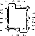
Fig. 1 is the front view of the anode side baffle in the embodiment of the invention 1;
Fig. 2 is the rearview of anode clapboard shown in Figure 1;
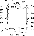
Fig. 3 is the front view of the cathode side separator in the embodiment of the invention 1;
Fig. 4 is the rearview of cathode separator shown in Figure 3;
Fig. 5 is the front view of the anode-side black box in the embodiment of the invention 1;
The amplification view of Fig. 6 for getting along the hatching 6-6 among Fig. 5;
Fig. 7 is the front view of the cathode side black box in the embodiment of the invention 1;
The amplification view of Fig. 8 for getting along the hatching 8-8 among Fig. 7;
Fig. 9 is the front view of another anode-side black box in the embodiment of the invention 1;
Figure 10 is the front view of the another anode-side black box in the embodiment of the invention 1;
Figure 11 is the longitudinal sectional view according to the major part of fuel cell of the present invention;
Figure 12 is near the amplification view the seal of fuel cell shown in Figure 11;
Figure 13 is near the amplification view the O-ring seals of existing fuel cell;
Figure 14 is the front view of the anode side baffle in the embodiment of the invention 2;
Figure 15 is the front view of the cathode side separator in the embodiment of the invention 2;
Figure 16 is the front view of the anode side baffle in the embodiment of the invention 2;
The amplification view of Figure 17 for getting along the hatching among Figure 16;
Figure 18 has the anode side baffle of improved seal of the embodiment of the invention 2 along the amplification view of the hatching 18-18 among Figure 16;
Figure 19 is the front view that has according to the cathode side separator of the seal of the embodiment of the invention 2;
Figure 20 is near the longitudinal sectional view the seal of cathode side separator shown in Figure 19;
Figure 21 has the amplification view of getting along the hatching 21-21 among Figure 19 according to the cathode side separator of the another kind of improved seal of the embodiment of the invention 2;
Figure 22 is the view of the first and second anode-side sealing sections of anode-side seal shown in Figure 16;
Figure 23 is the view of the first and second negative electrode sealing sections of cathode side seal shown in Figure 19;
Figure 24 is the front view of the anode side baffle in the comparison example 2;
Figure 25 is the front view of the cathode side separator in the comparison example 2;
Figure 26 is the front view of the another kind of anode side baffle in the embodiment of the invention 2;
Figure 27 is near the amplification view the fin that is arranged on the peripheral part of anode side baffle shown in Figure 26;
Figure 28 is near the amplification view the fin that is arranged on the peripheral part of the another kind of anode side baffle in the embodiment of the invention 2;
Figure 29 is a curve chart, there is shown the output characteristic of the fuel cell in example 1 and the comparison example 1;
Figure 30 is a curve chart, there is shown the output characteristic of the fuel cell of example 2 and comparison example 2;
Figure 31 is a curve chart, there is shown the output characteristic of the fuel cell of example 3 and comparison example 1;
Figure 32 is a curve chart, there is shown the output characteristic of the fuel cell of example 4 and comparison example 2;
Figure 33 is a curve chart, there is shown the output characteristic of the fuel cell of example 5 and comparison example 2;
Figure 34 is the front view of the cathode side separator in the embodiment of the invention 3;
Figure 35 is the rearview of cathode side separator shown in Figure 34;
Figure 36 is the front view of the anode side baffle in the embodiment of the invention 3;
Figure 37 is the front view of the cathode side seal in the embodiment of the invention 3;
Figure 38 is the front view of the anode-side seal in the embodiment of the invention 3;
The amplification view of Figure 39 for being done along the hatching 39-39 among Figure 37;
The amplification view of Figure 40 for being done along the hatching 40-40 among Figure 38;
Figure 41 is the front view of seal combination together time of the cathode side separator and the embodiment of the invention 3;
Figure 42 is the front view of seal combination together time of the anode side baffle and the embodiment of the invention 3;
Figure 43 is the illustraton of model in the gap between gas diffusion layers and the seal;
Figure 44 is a curve chart, there is shown the output voltage characteristic of the fuel cell in example 7 of the present invention and the comparison example 3;
Figure 45 is a curve chart, there is shown the output voltage characteristic of the fuel cell in example 7 of the present invention and the comparison example 4;
Figure 46 is a curve chart, there is shown the pressure loss and changes and be used to adjust relation between the parameter of the dividing plate of example 7 of the present invention and seal; And
Figure 47 is a curve chart, there is shown the output characteristic of the fuel cell in example 8 of the present invention and the comparison example 4.
Embodiment
According to an aspect of the present invention, anode-side seal and cathode side seal and polymer electrolyte film cooperatively interact and on anode-side seal and cathode side seal hermetic unit respect to one another battery are sealed.The anode-side seal has a fin that contacts with above-mentioned hermetic unit linearity with one of cathode side seal, and another seal then contacts Face to face with above-mentioned hermetic unit.Therefore, can prevent that fuel gas and oxidant gas from going out from fuel gas flow passage and the internal leakage of oxidant gas flow passage.
The present invention is with the following basis that is found to be: adopt such seal can save the required space of seal, but also can reduce the clamping load of battery pack, also can guarantee stable air-tightness simultaneously.
In another aspect of this invention, seal is arranged between polymer electrolyte film and each dividing plate and forms a sealing section, and sealing portion section has special cross sectional shape.Particularly, the anode-side seal is a flat, and the cathode side seal then is shaped as a kind of shape of wedge like, and its cross section is thinner in the side towards negative electrode, and the opposite side that is positioned on negative electrode peripheral part is then thicker.This configuration can be saved the required space of sealing section, reduces the clamping load that acts on the battery pack, can guarantee to exist between electrode and seal required minimum clearance in addition, to be used for draining and to be convenient to assembling.This configuration also helps the assembling of battery unit and guarantees and water can be discharged when the pressure loss of water is hanged down.
In aspect another, the present invention is based on following conclusion: can utilize the hydraulic diameter (d) of the structure of the gas flow channel on the dividing plate and seal and gaps between electrodes to limit the structure of seal.This gap is decided by and assembling characteristic relative restrictions factor.
That is to say that the present invention designs in the following manner: make electrode and cathode side seal be looped around one-sided gap " c1 " between the part around the negative electrode and the hydraulic diameter (d) in this gap satisfies formula (1), and preferably satisfy formula (2).
d<(D×1×P)/0.54L (1)
Wherein, " 1 " is the length in one-sided gap, " d " is the hydraulic diameter in one-sided gap, " L " is the length of the gas flow channel in each path of cathode side separator, " D " is the hydraulic diameter of the gas flow channel in each path on the cathode side separator, " P " is the number of paths of the gas flow channel on each cathode side separator, and
Hydraulic diameter=cross-sectional area ÷ section girth * 4
0.25mm<c1 (2)
When satisfying above-mentioned formula (e), just can reduce the negative effect of each size of component variation and assembly error, and final seal can make the structure of battery unit have very little pressure loss variation.
Aspect another, the present invention finds: but actual opereating specification can be limited by the ratio of pressure loss Pc in the gap and the pressure loss Pf in the gas flow channel.That is, effective when 0.9<Pc/Pf.
Polyisoprene, butyl rubber, vinyl acrylic rubber etc. and fluorocarbon rubber all can be used as the rubber layer of seal.Polyisobutene, vinyl acrylic rubber, butyl rubber and synthetic thereof all can be used as bonding agent.
Referring now to accompanying drawing, the present invention is described in detail by example.In this article, accompanying drawing only is used for the structure of each element is illustrated, and therefore, each relative positions and size there is no need very accurate.
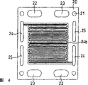
Fig. 1 is the front view of an anode side baffle, and Fig. 2 is its rearview.
An anode side baffle 10 has the total pore 12 of a pair of fuel gas, the total pore 13 of a pair of oxidant gas, the total pore 14 of a pair of cooling water, a pair of standby total pore 15 and four bolts hole 11.
This anode side baffle 10 has a gas flow channel 12b in the side towards anode, and this gas flow channel is connected to the total pore 12 of fuel gas with this, is used for anode fueling gas and fuel gas stream is discharged from anode.This gas flow channel 12b is made of a groove.Connect groove 12c with gas flow channel
12bCouple together with the total pore 12 of fuel gas.
Dividing plate 10 its dorsal part have one with this flow of cooling water passage 14b that total pore 14 of cooling water flow is connected.This passage 14b is made of two parallel grooves.Dividing plate 10 also has O shape circular groove groove 12a, 13a and the 15a that is used to hold O shape ring, these grooves be looped around the total pore 12 of fuel gas, the total pore 13 of oxidant gas and standby total pore 15 each around.In addition, also be provided with an O shape circular groove groove 14a who is used to hold O shape ring, this groove be looped around total pore 14 of cooling water and flow of cooling water passage 14b around.
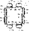
Fig. 3 is the front view of a cathode side separator, and Fig. 4 is its rearview.
A cathode side separator 20 has the total pore 22 of a pair of fuel gas, the total pore 23 of a pair of oxidant gas, the total pore 24 of a pair of cooling water, a pair of standby total pore 25 and four bolts hole 21.
This cathode side separator 20 has a gas flow channel 23b in the side towards negative electrode, and this gas flow channel is connected to the total pore 23 of oxidant gas with this, is used for discharging from negative electrode to negative electrode supply oxidant gas with oxidant gas.This gas flow channel 23b is made of two grooves.Connecting groove 23c couples together gas flow channel 23b and the total pore 23 of oxidant gas.
This dividing plate 20 dorsal part have one with this flow of cooling water passage 24b that total pore 24 of cooling water is connected.This water stream channel 24b is made up of two parallel grooves.
Fig. 5 is the front view of anode-side black box, and Fig. 6 is the local amplification view of sealing assembly.Fig. 7 is the front view of cathode side black box, and Fig. 8 is the local amplification view of sealing assembly.
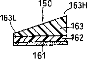
Being incorporated into anode-side black box 30 on the anode side baffle 10 comprises on film 4a, a side that is formed on film 4a made from polyimides and the anode-side seal 36 with fin 36a and the opposite side that is formed on film 4a and bonds to bond layer 5a on the anode side baffle 10.
For bond layer 5a, polyisobutene, vinyl acrylic rubber, butyl rubber and similar material all can be used alone as bonding agent, perhaps two or more combinations of materials are wherein become bonding agent.
Have the total pore 32 of fuel gas, the total pore 33 of oxidant gas, the total pore 34 of cooling water, standby total pore 35 and bolt hole 31 on film 4a and the bond layer 5a, these holes are corresponding with corresponding total pore on the anode side baffle 10 respectively; On this film and bond layer, be cut off with corresponding those parts of anode.
Anode-side seal 36 has each total pore hermetic unit (or parts) 32a, the 33a that surround the electrode hermetic unit (or parts) 37 of anode and surround total pore 32 of fuel gas and the total pore 33 of oxidant gas.Sealing part 36 also has hermetic unit (or parts) 38a, 38b, 38c and 38d, and these hermetic units link together the left end of total pore hermetic unit 32a, 33a and right-hand member and electrode hermetic unit 37. Hermetic unit 38a and 38b be positioned at anode side baffle 10 each be connected the both sides of groove 12c and can prevent that gas from connecting the side leakage of groove 12c from each.Hermetic unit 38c and 38d are positioned to be connected the both sides of the position of groove 23c corresponding (or place) with each of cathode side separator 20.Anode-side seal 36 also have respectively be looped around total pore 34 and 35 around total pore hermetic unit 34a and 35a.
The cross section of fin 36a is a triangle, and leg-of-mutton bottom is included on the first type surface of anode-side seal 36.The top 36b of a tip is exactly this vertex of a triangle, and the top surface of this tip is to the bottom and be compressed against on the cathode side seal 46 that will describe below one, and has an electrolytic thin-membrane between fin 36b and seal 46.
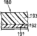
The cathode side sealed composite part 40 that is incorporated on the cathode side separator 20 comprises: on the plate-shaped cathode side seal 46 on film 4b who is made by polyimides, the side that is formed on film 4b and the opposite side that is formed on film 4b and bond to bond layer 5b on the cathode side separator 20.
For bond layer 5b, but the private bonding agent of doing of polyisobutene, ethylene-propylene rubber, butyl rubber and analog coverlet, and the composition of perhaps inciting somebody to action two or more materials wherein is as bonding agent.
Have the total pore 42 of fuel gas, the total pore 43 of oxidant gas, the total pore 44 of cooling water, standby total pore 45 and bolt hole 41 on film 4b and the bond layer 5b, these holes are corresponding with corresponding total pore on the cathode side separator 20 respectively; On this film and bond layer, be cut off with corresponding those parts of negative electrode.
What can be attached to anode side baffle 10 by the bond layer 5a with anode-side sealed composite part 30 is fixed on the anode side baffle 10 anode-side seal 36 on a side of anode.
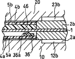
As shown in figure 11, fuel cell is to make shaping by a MEA being interposed in the anode side baffle 10 with anode-side sealed composite part 30 and having between the cathode side separator 20 of cathode side sealed composite part 40.This MEA comprises an anode 2a and a negative electrode 2b, is gripped with a hydrogen ion conductive polymer electrolyte film 1 between this anode and negative electrode.In Figure 11, Reference numeral 3 one of expression are fitted into the O shape ring among the groove 12a to 15a.
As shown in figure 12, this fuel cell is configured to make the top 36b of the tip of anode-side seal 36 to be pressed against on the cathode side seal 46, makes the version of electrolytic thin-membrane 1 between two seals.
By adopting above-mentioned anode-side and cathode side seal, just can save the required space of seal and reduce to act on clamping force on the battery pack, also can make air-tightness keep stable simultaneously.
This fuel cell comprises anode-side seal that is incorporated on the anode side baffle and the cathode side seal that is incorporated on the cathode side separator.This comprises seal: (a) pair of electrodes hermetic unit (or parts), this to the electrode hermetic unit clamping polymer electrolyte film around anode and the negative electrode; (b) a pair of total pore hermetic unit (or parts), this to hermetic unit clamping polymer electrolyte film around each of total pore of fuel gas and the total pore of oxidant gas; (c) hermetic unit of a pair of connection groove (or parts), this to hermetic unit clamping and be positioned at each and connect polymer electrolyte film on groove both sides.
On corresponding hermetic unit, the anode-side seal has a fin that can contact with the polymer electrolyte film linear mode with one of cathode side seal, and another seal then contacts Face to face with polymer electrolyte film.Therefore, just can keep air-tightness between polymer electrolyte film and the corresponding dividing plate.
In anode-side sealed composite part 30, the total pore 32 of fuel gas is separated with anode by the electrode hermetic unit 37 of total pore hermetic unit 32a and encirclement anode.Similarly, separate with anode by total pore hermetic unit 32a and electrode hermetic unit 37 in oxidizer manifold hole 33. Total pore 32 and 33 only can be opened with electrode separation by total pore hermetic unit 32a and 33a, as shown in Figure 9; Or only open with electrode separation by the electrode seal 37 that surrounds electrode, as shown in figure 10.
Cathode side sealed composite part 40 has the size of the entire main surface that can cover dividing plate 20, and this comprises: electrode hermetic unit, total pore hermetic unit and be connected the grooved seal part.But sealed composite part 40 also can have identical size with anode-side seal 36.
Figure 14 is the front view of an anode side baffle, and Figure 15 is the front view of a cathode side separator.
Anode side baffle 50 has the total pore 52 of a pair of fuel gas, the total pore 53 of a pair of oxidant gas, the total pore 54 of a pair of cooling water, a pair of standby total pore 55 and four bolts hole 51.
Cathode side separator 60 has the total pore 62 of a pair of fuel gas, the total pore 63 of a pair of oxidant gas, the total pore 64 of a pair of cooling water, a pair of standby total pore 65 and four bolts hole 61.
Figure 16 is the front view of anode side baffle 50, and wherein anode-side seal 56 is fitted in the groove 50a; And Figure 17 is the local amplification view of sealing part.Figure 19 is the front view of cathode side separator 60, and wherein cathode side seal 66 is fitted in the groove 60a; And Figure 20 is the local amplification view of sealing part.
Have of the seal groove 50a installation of the anode-side seal 56 of a fin 56a who is scheduled to along anode side baffle 50.
This anode-side seal 56 comprises: a first anode side seals section, sealing portion section are looped around gas flow channel 52b and this is to around the total pore 52 of fuel gas, to form the loop of a sealing.Sealing part 56 also comprises: total pore hermetic unit (or parts) 53a, 54a and 55a, and these hermetic units are looped around respectively around the total pore 53 of oxidant gas, the total pore 54 of cooling water and the standby total pore 55; And hermetic unit (or parts) 58c and 58d, these two hermetic units are positioned at the both sides of each connection groove 63c of cathode side separator 60.
First anode side seals section comprises following part: an electrode hermetic unit 57 that mainly is looped around around the gas flow channel 52b; Be looped around the total pore hermetic unit 52a on every side of outer half of the total pore 52 of fuel gas; And the hermetic unit 58a and the 58b that are positioned at the both sides of each connection groove 52c.Connecting groove 52c couples together total pore 52 with gas flow channel 52b.First anode side seals section is corresponding with twill shadow region shown in Figure 22.
Anode-side seal 56 also comprises hermetic unit 59a, 59b, 59c and 59d.Hermetic unit 59a couples together fuel gas total pore hermetic unit 52a and the total pore hermetic unit of oxidant gas 53a.Hermetic unit 59b couples together fuel gas total pore hermetic unit 52a and the total pore hermetic unit of cooling water 54a.Hermetic unit 59c couples together oxidant gas total pore hermetic unit 53a and standby total pore hermetic unit 55a.And hermetic unit 59d couples together cooling water total pore hermetic unit 54a and standby total pore hermetic unit 55a.
Second plate side seals section comprises following part: total pore hermetic unit 53a, 54a and 55a; With hermetic unit 59a, 59b, 59c and 59d, these hermetic units connect corresponding total pore hermetic unit.The total pore hermetic unit of the fuel gas 52a of this second sealing section and first anode side seal part is combined to form the loop of a sealing, and total pore 53,54 and 55 is positioned at the outside of this loop.
The first cathode side sealing section comprises following part: an electrode hermetic unit 67, this part mainly are looped around around the gas flow channel 63b; Be looped around the total pore hermetic unit 63a on every side of outer half of the total pore 63 of oxidant gas; Hermetic unit 68c and 68d, it is positioned at each both sides that connect groove 63c.Connecting groove 63c couples together total pore 63 with gas flow channel 63b.The first cathode side sealing section is corresponding with the twill shadow region shown in Figure 23.
This cathode side seal 66 also comprises hermetic unit 69a, 69b, 69c and 69d.Hermetic unit 69a couples together fuel gas total pore hermetic unit 62a and the total pore hermetic unit of oxidant gas 63a.Hermetic unit 69b couples together fuel gas total pore hermetic unit 62a and the total pore hermetic unit of cooling water 64a.Hermetic unit 69c couples together oxidant gas total pore hermetic unit 63a and standby total pore hermetic unit 65a.Hermetic unit 69d couples together cooling water total pore hermetic unit 64a and standby total pore hermetic unit 65a.
The second cathode side sealing section comprises following part: total pore hermetic unit 62a, 64a and 65a; Hermetic unit 69a, the 69b, 69c and the 69d that connect corresponding total pore hermetic unit.The total pore hermetic unit of the oxidant gas 63a of this second sealing section and the first cathode side hermetic unit is combined to form the loop of a sealing, and total pore 62,64 and 65 is positioned at the outside of this loop.
Fuel cell can be by being interposed in manufactured shaping between anode side baffle 50 and the cathode side separator 60 with a MEA in the following manner: the top 56b of the tip of the fin 56a on the anode-side seal 56 is pressed against on the cathode side seal 66, makes electrolytic thin-membrane between two seals.
By adopting above-mentioned anode-side and cathode side seal, just can save the required space of seal and reduce the clamping force that acts on the battery pack, guarantee stable air-tightness simultaneously.
This embodiment can also adopt a kind of polymer electrolyte film that is slightly less than dividing plate.The profile of this polymer electrolyte film is showed by the dotted line among Figure 16.When employing has the polymer electrolyte film of this size, will form the gap in the zone that hermetic unit 58a, 58b contact with polymer electrolyte film.Fuel gas can go out from the internal leakage of first anode side seals section by these gaps, goes out from the element cell internal leakage but second plate side seals section can prevent this gas that has leaked.Like this, for preventing gas leak, this second plate side seals section just becomes requisite section.In Figure 22, show the second sealing section that is positioned at the first anode side seals section outside.
In hermetic unit 68c, 68d and zone that polymer electrolyte film contacts, also be formed with the gap.Oxidant gas can pass through these gaps from the first cathode side sealing section internal leakage, but the second cathode side sealing section can prevent that this gas that has leaked from letting out from element cell.Therefore, this second cathode side sealing section just becomes and prevents air-flow requisite the section that leak outside.In Figure 23, show the outside that the second sealing section is positioned at the first cathode side sealing section.
In addition, because each of the second plate side seals section and the second cathode side sealing section is looped around around total pore area inside, rather than be looped around around the total pore that is connected with gas flow channel, the intersection that therefore gas can not take place in fuel cell is leaked.
As mentioned above, employing is provided with according to the anode side baffle of the anode-side seal of present embodiment and cathode side seal and cathode side separator just can guarantee stable air-tightness, even adopt under the situation by the undersized polymer electrolyte film shown in the dotted line among Figure 16, also be like this.The size of polymer electrolyte film can also be reduced like this, thereby the clamping load on the battery pack can be reduced to act on.
In the superincumbent explanation, fin 56a forms the corresponding hermetic unit of anode-side seal 56, and has identical height.But can improve sealing effectiveness by the height of setting this fin in the following manner: do not make to be higher than and the contacted fin of polymer electrolyte film with the contacted fin of polymer electrolyte film, difference in height equals the thickness of polymer electrolyte film.
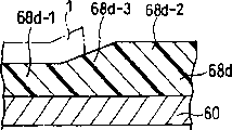
Figure 18 is provided with the amplification view that the dividing plate 50 of such anode-side seal is got along the hatching 18-18 among Figure 16.With regard to the fin 56a of seal 56, represent by 56a-1 with polymer electrolyte film 1 contacted part, and do not represent by 56a-2 with the contacted part of polymer electrolyte film with dotted line illustrated dimension among Figure 16.Fin 56a-2 is higher than fin 56a-1, and difference in height equals the thickness of polymer electrolyte film.Fin 56a-1 is connected with fin 56a-2 by becoming big part 56a-3 highly gradually.
Can substitute the height that increases fin 56 itself, increase the height (thickness) of fin bottom, with the height of final increase fin.In addition, can not change the height of the fin of anode-side seal, but change the height (thickness) of cathode side seal.Figure 21 has the amplification view that the cathode side separator of this seal is got along the hatching 21-21 among Figure 19.With regard to the hermetic unit 68d of seal 66, represent by 68d-1 with polymer electrolyte film 1 contacted part, and do not represent by 68d-2 with the contacted part of polymer electrolyte film with dotted line illustrated dimension among Figure 16.The distance that this part 68d-2 exceeds than part 68d-1 equals the thickness of polymer electrolyte film.Part 68d-1 is connected with part 68d-2 by becoming big part 68d-3 highly gradually.Other hermetic unit also can be constructed in the following manner: do not make to be higher than and the contacted part of polymer electrolyte film with the contacted part of polymer electrolyte film.
The position that is noted that anode-side seal and cathode side seal is not to be corresponding in some part, that is, the total pore hermetic unit of oxidant gas and with the total pore of oxidant gas be positioned at separated those parts of anode of anode-side seal shown in Figure 16; With the total pore hermetic unit of fuel gas with the total pore of fuel gas and separated those parts of negative electrode that are positioned at cathode side seal shown in Figure 19.But these two seals are flexible, and when forming battery pack, these two seals can bear the suitable pressure from anode side baffle and cathode side separator.Therefore, even the position of two seals is not corresponding, also can realize good sealing with direct contact of adjacent separator by making one of two seals.
At the above-mentioned non-counterpart place of one of them seal of aiming at mutually with another seal with these parts as cover plate and realize sealing.For example, in Figure 16, can between hermetic unit 58a that aims at the cathode side seal and 58b, be provided with one and cover each and be connected the cover plate of groove 52c.In Figure 19, can between hermetic unit 68c that aims at the anode-side seal and 68d, be provided with one and cover each and be connected the cover plate of groove 63c.
Can be by on the groove that seal is integrally molded into dividing plate or by the mode that mold formed in advance seal is fitted in the groove sealing part being arranged in the seal groove of dividing plate.
Figure 26 and 27 shows the anode side baffle 50 with another anode-side seal 76.Can be by in the groove 50a that seal 76 is fitted into dividing plate 50 and sealing part 76 integral body are connected on the anode side baffle shown in Figure 14 50.Sealing part 76 is with the difference of seal 56: except total pore 53 to 55, bolt hole 51 with by the following first anode side seals section area surrounded, seal 76 is covered with the first type surface of dividing plate 50.Sealing part 76 has a fin 76a, and the position at this fin place is identical with the position of the fin 56a of seal 56 shown in Figure 16.In Figure 26, the top 76b of the tip of fin 76a is expressed as a line.Sealing part 76 can prevent that the dividing plate of a pair of clamping MEA is in contact with one another, thereby prevents to produce short circuit between two dividing plates.
Anode-side seal 76 comprises a first anode side seals section, and sealing portion section is looped around gas flow channel 52b and this is to around the total pore 52 of fuel gas, to form the loop of a sealing.Sealing part 76 also comprises: total pore hermetic unit 73a, 74a and 75a, and these hermetic units are looped around around each of the total pore 53 of oxidant gas, the total pore 54 of cooling water and standby total pore 55; And hermetic unit 78c and 78d, these hermetic units are positioned at the both sides of each connection groove 63c of cathode side separator 60.Anode-side seal 76 also has the hermetic unit 79a that connects total pore hermetic unit 72a and 73a, connects the hermetic unit 79b of total pore hermetic unit 72a and 74a and the hermetic unit 79c that is connected total pore hermetic unit 74a and 75a.
First anode side seals section comprises following part: an electrode hermetic unit 77 that mainly is looped around around the gas flow channel 52b; Be looped around the total pore hermetic unit 72a on every side of outer half of the total pore 52 of fuel gas; And hermetic unit 78a and 78b, it is positioned at each both sides that connect groove 52c.The position of these hermetic units is corresponding with the hermetic unit of seal shown in Figure 16.
As shown in figure 28, can also provide an anode-side seal 86 for anode side baffle 50, the sealing part not only covers this first type surface, but also is covered with the side of dividing plate 50, also has a fin 86a in addition on the position identical with fin 56a shown in Figure 16.Reference numeral 86b represents the top of the tip of fin 86a.Sealing part 86 prevents from may be short-circuited after making fuel cell, and prevents to be short-circuited between the dividing plate of MEA in a pair of clamping.
Example 1
(i) manufacturing of dividing plate
In example 1, the cathode side separator 20 shown in the anode side baffle shown in Fig. 1 and 2 and Fig. 3 and 4 is made by isotropic graphite cake is processed.The thickness of dividing plate is 3mm.The width that constitutes the groove of gas and cooling-water duct is 2mm, and its degree of depth is 3mm.
The (ii) manufacturing of seal
Shown in Fig. 5 to 8, the sealed composite part 30 and 40 that will have in the example 1 of bond layer creates.
With a thickness is that the thin polymer film 4a of 100 μ m is placed in the mould.Mould by matched moulds after, at 200 ℃ temperature and 150kgf/cm
2The molding pressure effect under, fluorubber is carried out injection molding processing, on thin polymer film 4a, to form a predetermined seal 36.Equally, on being the thin polymer film 4b of 100 μ m, thickness is molded into a seal 46.Then, under 200 ℃ temperature conditions, its secondary cross-linking that carried out 10 hours is handled.After this, be 25 μ m with thickness and transfer to respectively on thin polymer film 4a and the 4b, and cover on the surface of bond layer 5a and 5b with a release film of making by polypropylene by bond layer 5a and 5b that butyl rubber is made.
The thickness of anode-side seal 36 is 100 μ m, and its width is 3mm.The height of the fin 36a that stretches out on the first type surface by seal 36 is 300 μ m.The thickness of anode-side seal 46 is 125 μ m.Utilize finishing mould antianode side and a cathode side sealed composite part 30 and 40 to carry out punch process, with total pore of being formed for fuel gas and oxidant gas and oxidant gas, cooling water and standby total pore 32 to 35 and 42 to 45 and bolt hole 31,41 and towards the electrode of these parts.
The finished product sealed composite part 30 and 40 that will have bond layer is placed on respectively on dividing plate 10 and 20 and with 100 ℃ temperature and the pressure loading of 2000kgf it is carried out 1 minute hot pressing.
The (iii) manufacturing of MEA
Platinum grain by particle mean size being about 30 is placed on 1: 4 weight ratio and prepares the electrolyte catalyst fines on the acetylene black carbon powder.This catalyst fines that is distributed in the isopropyl alcohol mixes mutually with perfluorocarbon sulfonic acid powder (perfluorocarbon sulfonic acidpower) in being distributed in alcohol, thereby forms electrode paste.By screen printing the kind electrode muddle is layed onto on the side of the non-manufacturing fabric of carbon fiber that thickness is 250 μ m, thereby forms a catalyst layer.Like this, just can obtain electrode.In this catalyst layer, the content of platinum is 0.5mg/cm
2, the content of perfluorocarbon sulfonic acid is 1.2mg/cm
2
Negative electrode and the anode made in the above described manner are of identical composition.Hydrogen ion conductive polymer electrolyte film is 100cm can make the mode of the catalyst layer that forms by printing in facing be interposed in a pair of area
2Electrode between.The final structure that forms is carried out hot pressing, to produce membrane-electrode assemblies (MEA).Used hydrogen ion conductive polymer electrolyte film is that a kind of thickness is the very thin film of perfluorocarbon sulfonic acid of 25 μ m.
This electrolytic thin-membrane has identical size with dividing plate, and utilizes the finishing mould that it is carried out punching press, thereby forms a plurality of holes, and these holes will become the total pore of a pair of fuel gas, the total pore of a pair of cooling water and the total pore of a pair of oxidant gas.
The (iv) manufacturing of fuel cell
Figure 11 is the longitudinal sectional view of the major part of fuel cell.
Element cell is to assemble by a MEA being interposed in the anode side baffle 10 with anode-side sealed composite part 30 and having between the cathode side separator 20 of cathode side sealed composite part 40.This MEA comprises a hydrogen ion conductive polymer electrolyte film 1 that is arranged between pair of electrodes 2a and the 2b.Here, in the O shape ring 3 O shape circular groove groove 12a to 15a that are fitted on the anode side baffle 10.When a plurality of element cells are stacked together, just can combine cooling end section of formation, thereby its flow of cooling water passage 14b and 24b are faced with each other by the dividing plate 10 and the dividing plate 20 that will connect element cell.
Like this, 50 element cells can be stacked to a battery pack, and collector plate is connected with each end of battery pack respectively with an insulation board.The final assembly that forms is sandwiched between between the stainless steel end plate and utilizes clamping bar with the clamping load of 700kgf it to be clamped, to produce a fuel cell.This fuel cell is named as battery A.
Can utilize impact paper that the surface pressing that acts on MEA and the dividing plate is checked, and the surface pressing that acts on the MEA is 10kgf/cm
2Found that: the reaction force of seal is 200kgf.
This battery A is carried out leak test.This leak test is the total pore by the sealing outlet side, is 0.5kgf/cm with pressure
2Helium be incorporated in the battery A from the total pore of entrance side, measure gas then and flow into flow velocity in the battery A.As a result, do not find air, fuel gas and leakage of cooling water, therefore can conclude: battery A is no problem aspect the fluid seal performance.
Comparison example 1
Go out to have traditional O shape circular groove groove 236a shown in Figure 13 and the dividing plate 210 and 220 of 246a by isotropic graphite cake being carried out processing and manufacturing.The width of this O shape circular groove groove 236a and 246a is 1.5mm, and the degree of depth is 0.8mm. O shape ring 236 and 246 is to utilize predetermined mould to make by compression moulding.These O shapes ring is that 60 fluorubber is made by rubber hardness.
Except use dividing plate 210 and 220 and O shape ring 236 and 246 alternate example 1 in dividing plate 10,20 and sealed composite part 30 and 40, produce a kind of fuel cell with the method identical with example 1.This fuel cell is named as battery B.Except for consistent with the shape of O shape ring and to size made change, other element of battery pack has identical structure with counter element in the example 1.
To the detection of battery B gas leakage property, the mode of detection is identical with example 1.As a result, do not find air, fuel gas and leakage of cooling water, so just can conclude: battery B does not have problems aspect fluid sealability.
When each of battery A in the example 1 and the battery B in the comparison example 1 remains on 85 ℃ following time of temperature, will be by humidification and be heated to that to make its dew point be that 83 ℃ hydrogen supplies to anode, and will be by humidification and be heated to that to make its dew point be that 78 ℃ air supplies to negative electrode.As a result, not under the situation of outside output electric energy, when not having load, the open circuit voltage of two kinds of batteries is 50V.
In addition, can be 80% at fuel availability, oxygen utilization rate be 40% and current density be 0.5A/cm
2Condition under, the output performance of battery A and battery B is estimated.Evaluation result as shown in figure 29.Can conclude: the battery A in the example 1 of the present invention has identical performance with battery B in the comparison example 1.
Example 2
Shown in Figure 14 and 15, anode side baffle 50 in the example 2 and cathode side separator 60 are made by isotropic graphite cake is carried out machine work.Anode-side and cathode side separator 50,60 have seal groove 50a and 60a respectively, and the width of these grooves is 4mm, and the degree of depth is 1mm. Dividing plate 50 and 60 thickness are 3mm.These grooves constitute flow channel on the dividing plate both sides, the width of these grooves is 2mm, and its spacing is 3mm.
After this, predetermined seal is molded on dividing plate 50 and 60, thereby forms the anode side baffle with seal 56 50 in the example 2, shown in Figure 16 and 17 and have the cathode side separator 60 of seal 66, shown in Figure 19 and 20.
This seal can be molded on the dividing plate by following step: dividing plate is placed in the mould, and with the mould matched moulds, and then at 200 ℃ temperature and 150kgf/cm
2The molding pressure effect under fluorubber is carried out injection molding processing.Under 200 ℃ condition, its secondary cross-linking that carried out 10 hours is handled.
The thickness of anode-side seal 56 from the surface of anode side baffle 50 is 100 μ m, and its width is 4.5mm.The fin 56a of anode-side seal 56 is 300 μ m from the height of the first type surface of seal 56.The thickness of cathode side seal 66 from the surface of cathode side separator 60 is 250 μ m, and its width is 4.5mm.
Except the size of polymer electrolyte film is reduced to the size shown in the dotted line among Figure 16, and this undersized can be made MEA in the manner as in example 1 outside the size of dividing plate.
Dividing plate that utilization is made and the MEA that makes in the manner described above just can adopt the mode identical with example 1 to produce fuel cell.This fuel cell is named as battery C.
In the manner as in example 1 battery C is carried out the gas leakage inspection.As a result, do not observe air, fuel gas and leakage of cooling water, can conclude: battery C does not have problems as its fluid seal performance of fuel cell of a stacked-up type.
Comparison example 2
As shown in figure 24, produce a anode side baffle 90 in the same manner as in example 2 with seal 96.Sealing part 96 has the structure same with the seal 56 shown in Figure 16, except sealing part 96 does not have hermetic unit 59a, 59b, 59c and the 59d of seal 56.And, as shown in figure 25, produce a cathode side separator 100 in the same manner as in example 2 with seal 106.Sealing part 106 has the structure same with the seal 66 shown in Figure 19, except sealing part 106 does not have hermetic unit 69a, 69b, 69c and the 69d of seal 66.Except adopting dividing plate 90 and 100, can produce fuel cell in the same manner as in example 2.But this fuel cell called after battery D.In the manner as in example 1 to the inspection of battery D gas leakage property.
Since the fin 96a of seal 96 have some not with the contacted part of the electrolytic thin-membrane part of dotted line (in the Figure 24 by), therefore these parts are carried out gas leakage and detect with the gas pressure of 5kPa.Therefore, can find: the battery C comparison in the example 2 has better sealing property than the battery D in the example 2.
When each of battery C and D is remained on 85 ℃, will be by humidification and be heated to that to make its dew point be that 83 ℃ hydrogen supplies to anode, and will be by humidification and be heated to that to make its dew point be that 78 ℃ air supplies to negative electrode.As a result, do not have at electric energy under the situation of outwards output, when not having load, the battery C in the example 2 of the present invention produces the open circuit voltage of a 50V, and the battery D in the comparison example 2 then produces the open circuit voltage of a 42.5V.Have been found that: there is the problem of gas crossover in the battery D of comparison example 2.
In addition, can be 80% at fuel availability, oxygen utilization rate be 40% and current density be 0.5A/cm
2Condition under the output characteristic of battery C is estimated.Evaluation result as shown in figure 30.Have been found that: the battery C comparison of example 2 has more performance than the battery D in the example 2.
Example 3
As shown in figure 18, the fin 56a's of anode-side seal 56 highly changes.This fin 56a with the contacted part 56a-1 of polymer electrolyte film be 300 μ m from the height of first type surface, and be not 350 μ m from the height of first type surface with the contacted part 56a-2 of polymer electrolyte film.The part 56a-3 slight inclination that connects above-mentioned two parts.Except the variation of fin height, battery C2 makes shaping in the same manner as in example 2.
Battery C2 in this example and the battery C in the example 2 are compared test, and purpose is except detected pressures changes, and in the manner as in example 1 its sealing property is detected.As a result, for battery C2, just detect gas leakage up to 300kPa; But for battery C, when detected pressures is 200kPa, just detected gas from house steward to external leakage.Therefore, we find: the battery C2 in the example 3 has better sealing property than the battery C in the example 2.
The reason that this result occurs is as described below.The seal interference degree that is positioned at the hermetic unit in the polymer electrolyte film outside can be improved by the thickness that increases film.Term " seal interference degree " is meant the thickness of the hermetic unit of the effect of being squeezed, and seal need produce enough elastic force by this thickness, thereby realizes sealing function.In addition, produce at thickness on the position of difference in height, can compensate or reduce the difference on this height by the height of adjusting fin because of film.Therefore, just can guarantee on all hermetic units, all to have stable seal interference amount, thereby improve sealing property.
Example 4
Produce an anode side baffle 50 and a cathode side separator 60 in the same manner as in example 2.And, produce anode-side seal 56 and cathode side seal 66 respectively.
Can be by in the groove 50a, the 60a that seal 56 and 66 are fitted into dividing plate 50 and 60 and seal 56 and 66 is connected on dividing plate 50 and 60.Because the seal in this example is wider than traditional O shape sealing gasket, therefore this seal has better handling property in assembling process.
Except adopting the anode-side of making in the manner described above and cathode side separator 50,60, produce a kind of fuel cell in the same manner as in example 2.This battery can be named as battery E.
In the manner as in example 1 to the detection of battery E gas leakage property.As a result, do not observe the leakage of air, fuel and gas leakage water, can conclude: the fluid seal performance of battery E does not have problems.
When battery E is remained on 85 ℃, will be by humidification and be heated to that to make its dew point be that 83 ℃ hydrogen supplies to anode, and will be by humidification and be heated to that to make its dew point be that 78 ℃ air supplies to negative electrode.Like this, do not have at electric energy under the situation of outwards output, when not having load, battery E produces the open circuit voltage of a 50V in this example.
Output performance to battery E under the condition identical with example 1 detects.The evaluation result of the battery B of battery E and comparison example 1 as shown in figure 31.Can conclude: the battery E comparison in this example has identical performance than the battery B in the example 1.
For seal being bonded on the dividing plate better, a kind of bonding agent of being made by butyl rubber can be applied on the surface that will be connected to the seal on the dividing plate in this example.Even adopting under the condition of this seal, still can conclude: this fuel cell performance has identical performance with battery E in this example.
Can vibrate tempestuously with the whole dividing plate that combines of seal, but seal can not thrown off from dividing plate.Can also conclude: in assembling process, this vibration can not make the dividing plate that makes up with the seal one produce any problem.
Example 5
Shown in the accompanying drawing among the embodiment 2 26 and 27, an anode-side seal 76 is set on anode side baffle 50 in the mode identical with example 2.
The thickness of this anode-side seal 76 is from the surface of anode side baffle 50 100 μ m, and the fin 76a of seal 76 is 300 μ m from the height of the first type surface of seal 76.
In assembling process,, can perhaps seal can be molded as certain part that does not cover dividing plate with covering the part excision of seal 76 on the whole surface of dividing plate 50 substantially so if certain part of dividing plate 50 should not cover with seal 76.
Except adopting anode-side seal 76, produce a kind of fuel cell in the same manner as in example 2.But this fuel cell called after battery F.
Under the condition identical with example 1 to the inspection of battery F gas leakage property.As a result, do not observe the leakage of air, fuel gas and gas leakage water, can conclude: fuel F does not have problems aspect fluid tight characteristics.
When battery F is remained on 85 ℃, will be by humidification and be heated to that to make its dew point be that 83 ℃ hydrogen supplies to anode, and will be by humidification and be heated to that to make its dew point be that 78 ℃ air supplies to negative electrode.As a result, outwards do not export under the situation of electric energy having, when not having load, the battery F in this example produces the open circuit voltage of a 50V.
Output performance to battery F under the condition identical with example 1 detects.To the evaluation result of the battery D in battery F and the comparison example 2 shown in figure 32.As a result, can conclude: the battery F comparison in this example has more performance than the battery D in the example 2.
In addition, because the first type surface of anode side baffle 50 covers with seal 76, therefore the conduction foreign matter that is mixed in wherein can not produce short circuit problem.
Example 6
Shown in the accompanying drawing among the embodiment 2 28, anode-side seal 86 is arranged on the anode side baffle 50 in the same manner as in example 2.This anode side baffle 86 is configured to cover the version of the side of anode side baffle 50, and its thickness is 100 μ m.
Except adopting anode-side seal 86, can produce a kind of fuel cell in the same manner as in example 2.This fuel cell can be named as battery G.
In the manner as in example 1 to the detection of battery G gas leakage property.As a result, do not observed air, fuel gas and leakage of cooling water, can conclude: the fluid tight characteristics of battery G does not have problems.
When battery G is remained on 85 ℃, will be by humidification and be heated to that to make its dew point be that 83 ℃ hydrogen supplies to anode, and will be by humidification and be heated to that to make its dew point be that 78 ℃ air supplies to negative electrode.As a result, outwards do not export under the situation of electric energy having, when not having load, the battery G in this example produces the open circuit voltage of a 50V.
Under the condition identical, battery G is carried out the detection of output performance with example 1.The evaluation result of battery D in battery G and the comparison example 2 as shown in figure 33.As a result, can conclude: the battery G comparison in this example has higher performance than the battery D in the example 2.
In addition, because the first type surface of anode side baffle 50 covers with seal 86, therefore the conduction foreign matter that is mixed in wherein can not cause short circuit.In addition, the side of dividing plate 50 covers with seal 86, and therefore the conduction foreign matter that is present on the fuel cell surface can not cause short circuit yet, so just can be reduced in the possibility of generation electroshock in the use of fuel cell.
Figure 34 is the front view of cathode side separator of the fuel cell of present embodiment, and Figure 35 is its rearview.Figure 36 is the front view of anode side baffle.
This cathode side separator 110 has the total pore 111 of a pair of oxidant gas, the total pore 112 of a pair of fuel gas, the total pore 113 of a pair of cooling water and four bolts hole 119 that are used to install fishbolt.This dividing plate 110 the side towards negative electrode have one with the gas flow channel 115 that should be connected to total pore 111.This dividing plate 110 have at its back side one with this flow of cooling water passage 114 that total pore 113 of cooling water is connected.Also have one on this back side and be looped around total pore 113 and flow channel 114 seal groove 116 on every side and each the seal groove 117 and 118 on every side that is looped around total pore 111 and 112.This dividing plate 110 also has the total pore 113B of a pair of vacation, and this is used for balancing each other with total pore 113 to the total pore of vacation.
An anode side baffle 120 has the total pore 121 of a pair of oxidant gas, the total pore 122 of a pair of fuel gas, the total pore 123 of a pair of cooling water, false total pore 123B and four bolts hole 129 that are used to install fishbolt.This dividing plate 120 the side towards anode have one with the gas flow channel 124 that should be connected total pore 122.Identical with cathode side separator, the back side of this dividing plate 120 also comprises: one with this flow of cooling water passage that total pore 123 of cooling water is connected; One is looped around total pore 123 and the parameatal seal channel of flow of cooling water; With each seal channel on every side that is looped around total pore 121 and 122, but not shown in figures.
As shown in figure 37, cathode side seal 150 has one and is looped around on the cathode side separator 110 this to the part 151 around the total pore 111 of oxidant gas and the gas flow channel 115, thereby forms the loop of a sealing.Sealing part 150 also comprises: be looped around the total pore 112 of each fuel gas annular section 152 on every side; Vertical component 158 and horizontal component 154 that part 152 and part 151 are coupled together; Be looped around annular section 153 and 153B around each of the total pore of cooling water 113 and false total pore 113B, this two parts 153 are connected to each other with 153B and are in the same place; And the part 156 and 157 that end and the part 151 of part 153 and 153B linked together.As shown in figure 39, sealing part 150 has a kind of three-decker that is made of bond layer 161, resin film 162 and rubber layer 163.Part 151 is processed to the shape of wedge like, and its cross section is thinner in the inboard, and thicker in the outside.Part 152,153 and 153B are processed to the shape of wedge like, and its cross section is that total pore side is thicker in the inboard, and the outside is then thinner.
Part 154,156,157 and 158 cross sections that also have wedge shape.Although these its inboard of part or outsides with wedge-shaped cross-section are thicker, it is thicker that it is preferably in the inboard, and thinner in the outside.
As shown in figure 38, anode-side seal 180 has respectively and total pore 181,182,183,183B and the hole 189 of total pore 121,122,123,123B and hole 129 UNICOMs and the cut-out 184 relative with anode.Although with the structural similarity of seal 150, seal 180 also has a kind of three-decker that is made of bond layer 191, resin film 192 and rubber layer 193, and sealing part 180 is the flat boards with uniform thickness, as shown in figure 40.
With this cathode side seal 150 so that its bond layer mode down is placed on the surface of negative electrode and by hot pressing it being attached on the dividing plate of cathode side separator 110.Similarly, with anode-side seal 180 so that its bond layer mode down is placed on receiving on this dividing plate 120 of anode side baffle 120 on the surface of anode and by thermocompression bonded.Figure 41 and 42 shows cathode side separator and anode side baffle respectively, and seal is combined on these dividing plates respectively in the above described manner.
An element cell can be shaped by a MEA being clamped in make between the dividing plate that links together with seal, and wherein MEA comprises a polymer electrolyte film that is arranged between the pair of electrodes.Between adjacent element cell, cooling segment is arranged on the junction at the back side of the back side of cathode side separator and anode side baffle.Between these dividing plates that link together, there are a plurality of O shape rings to be fitted in groove shown in Figure 35 116,117 and 118.This assembling procedure is as described below.
At first, a plurality of pilot pins are arranged in the assembling jig, the anode side baffle 120 that will be connected with seal then is placed on the pilot pin.Then, according to anode gas diffusion layer is not installed MEA carefully with the mode of the imbricate that is cut off part 184 of seal 180 along pilot pin.
Have the gap between pilot pin in being arranged on anchor clamps and the corresponding parts that assembled.Because the size of MEA can acute variation take place with the difference of the humidity in the assembly environment, therefore should leave a very big gap.In order stably to assemble MEA, the gap of a 1mm need be set on targeting part.
After MEA is set, just cathode side separator 110 can be installed.Because this dividing plate is not transparent, therefore just can not observe directly cathode gas diffusion layer and the seal of MEA, so just need carry out fitting operation along pilot pin.Preferably the cathode gas diffusion layer with MEA is arranged on the center of cathode side seal 150.But the combined result of the scale error of the gap of anchor clamps and MEA and dividing plate will cause dislocation.
When adopting the conventional seals part of flat type, gas diffusion layers will cover near the upper limit of maximum possible displacement the seal edge, thereby cause the not enough problem of sealing.If this gap becomes big for ease of assembling, air-flow will pass through Clearance Flow so, and can not supply to electrode.
On the contrary, when employing has the present invention's the seal of wedge-shaped cross-section, even gas diffusion layers is because scale error and cover the bottom 163L of seal 150 to a certain extent also can be finished sealing function by the higher part 163H of wedge shaped seal.So just can prevent that gas from leaking from the part 151 of seal 150, thereby guarantee enough sealing properties.In addition, because seal is a wedge shape, therefore just can between sealing part and gas diffusion layers, obtaining very big gap on the in-plane of dividing plate, and still keep very little along the gap of short transverse.Therefore, just can but not flow through the problem that reduces its power generation performance in gas flow channel owing to gas flows from this gap.
Can know from above-mentioned explanation and see: be preferably in the part of the encirclement negative electrode on the part 151, promptly the oblique dash area in Figure 37 can be processed to the shape of wedge like, and its cross section is thinner in the inboard, and thicker in the outside.For for the other parts the part 151, wedge-shaped cross-section can be in the inboard or the outside thinner, but it is thinner to be preferably in the inboard, and thicker in the outside, this is the same with the part of surrounding electrode.
As mentioned above, adopt according to seal of the present invention, just can by will be placed on the anchor clamps that have a plurality of pilot pins with the anode side baffle that seal links together and with MEA along the pilot pin setting, cathode side separator is installed then.Just can cover the mode assemble directly perceived and carefully at the edge of the cut part 184 on the seal 180 by this operation not make anode gas diffusion layer.Therefore, just can reduce the variation of the pressure loss that the rigging error because of anode-side produces, thereby improve the utilance of active gases.At cathode side, the joint of cathode gas diffusion layer and seal can not directly be seen in assembling process, but adopt the seal with wedge-shaped cross-section just can prevent the gas leakage problem that produces owing to rigging error.
Example 7
Catalyst fines can be that 25% platinum grain is placed in a kind of acetylene carbon black powder and prepares by particle mean size being about 30 , percentage by weight.This catalyst fines mixes mutually with the perfluorocarbon sulfonic acid in being distributed in alcohol.This mixture is applied to the side that thickness is the non-manufacturing fabric of carbon fiber of 250 μ m,, thereby forms an electrolyte catalyst layer then with its oven dry.In the final electrode that forms, the content of platinum is 0.5mg/cm
2, and the content of perfluorocarbon sulfonic acid is 1.2mg/cm
2
The negative electrode of making in the manner described above has identical component with anode.They can combine by following manner: hot pressing is carried out in the both sides of core that area are slightly larger than the hydrogen ion conductive polymer electrolyte film of electrode, and the catalyst layer and the electrolytic thin-membrane that make printing form are in contact with one another.Like this, just produce a kind of membrane-electrode assemblies (MEA).This hydrogen ion conductive polymer electrolyte film is the very thin film of perfluorocarbon sulfonic acid that a thickness is 175 μ m, and this film has identical size with following dividing plate.Utilize the finishing mould that this electrolytic thin-membrane is carried out punching press, with the corresponding total pore corresponding hole that be used for fuel gas, cooling water and oxidant gas of formation with dividing plate.
To the structure of each part of fuel cell in this example be illustrated below.
Have the cathode side separator 110 of said structure and anode side baffle 120 and be by being thereby that airtight isotropic graphite cake of 3mm carries out the mode that machine work forms gas flow channel and total pore and makes to thickness.The width that constitutes the groove of gas and flow of cooling water passage is 1.5mm, and its spacing is 3mm.Oxidant gas flow passage, fuel gas flow passage and flow of cooling water passage become to crawl and arrange and be made up of with six parallel grooves seven parallel grooves, four parallel grooves respectively.
Anode-side seal 180 is a kind of thin plates, this thin plate comprises polyimide film 192 and fluororubber layer 193 that thickness is 125 μ m that a thickness is 100 μ m, and polyimide film 192 to be positioned at a side of thin plate and to have a thickness be 25 μ m and the bond layer 191 made by butyl rubber, and fluororubber layer 193 is formed on the opposite side of this thin plate.Fluororubber layer 193 is formed on the polyimide film 192 by molded.Utilize the finishing mould that this thin plate is carried out punching press, thereby form a plurality of total pores, bolt hole and a part relative (cut part 184) with electrode.This part relative with electrode is sized to, and makes between electrode part and this part in the gap of a side to be 0.25mm.
Cathode side seal 150 is by on the polyimide film 162 that fluorubber 163 is molded into a thickness is 100 μ m, thereby mode that the zone that will need to seal is surrounded is made.The width of this fluorubber 163 is 3mm, and the height of its wedge-shaped cross-section is 300 μ m in upper side, and is being 50 μ m than downside.That is, as described in embodiment 3, the cross section of a part 151 is thinner in the inboard, and thicker in the outside.The cross section of part 152,153 and 153B is thicker in the inboard, and thinner in the outside.Fluorubber is molded on the polyimide film by following step: polyimide film is arranged in the mould, and with the mould matched moulds, and under 200 ℃ temperature conditions and 150kgf/cm
2The molding pressure effect under carry out molded to fluorubber.Under 200 ℃ condition, its secondary cross-linking that carried out 10 hours is handled.Then, be 25 μ m with a thickness and transfer on this polyimide film, and cover on the surface of bond layer with a release film of making by polypropylene by the bond layer 161 that butyl rubber is made.Utilize the finishing mould that the thin plate of final formation is carried out the punching press processing, thereby form a plurality of total pores, bolt hole and a part relative with electrode.The size of part relative with electrode is determined in the following manner: making between electrode part and this part in the gap of a side is 0.25mm.
Produced like this seal 150 and 180 is placed on respectively on dividing plate 110 and 120 and under 100 ℃ the temperature conditions and under the compressive load effect of 2000kgf it is carried out hot pressing 1 minute.
After this, as mentioned above, a plurality of pilot pin settings are fixed on the assembling jig, then anode side baffle, MEA, cathode side separator order are assembled along these pilot pins.Like this, just 50 element cells can be stacked together.The electrode area of MEA is 100cm
2Collector plate and an insulation board are connected with each of the battery pack that forms respectively, and are interposed in this battery pack between the stainless steel end plate and utilize clamping bar with the anchor clamps load of 700kgf it to be clamped.Utilize impact paper to detect being applied to the surface pressing that acts on MEA and the dividing plate, can find: the surface pressing that acts on the MEA is 10kgf/cm
2As a result, just can find: the reaction force of seal is 200kgf.
To these fuel cell gas leakage property detections of making.This gas leakage detection is undertaken by following manner: with the sealing of the total pore of outlet side, from the total pore of entrance side with 0.5kgf/cm
2Pressure import helium in the fuel cell and measure gas and flow into flow velocity in this fuel cell.As a result, can observe: do not have air, fuel gas and leakage of cooling water, therefore can conclude: this fuel cell does not have problems as its fluid seal performance of fuel cell of stacked type.
Comparison example 3
Traditional plate seal is used for oxidant gas side is sealed.Its formation is identical with the formation of example 7, except the seal of oxidant gas side is the flat board.Identical with the mode of example 7, utilize assembling jig that 50 element cells are stacked, and the fuel cell of final formation is carried out leak test according to identical mode.Because the surface pressing that acts on the MEA is 10kgf/cm at clamping load during for 2000kgf
2, so clamp operation is to carry out under the pressure effect of 2000kgf.Like this, some battery will make gas leak into fuel gas side from oxidant gas side to external leakage or intersection, has perhaps both existed and has leaked, and exists again to intersect and leaks, and will make seal failure like this.The condition of leak test is identical with the inspection condition of example 7.
After finishing this detection, the fuel cell of example 7 and the fuel cell of comparison example 3 are carried out resolution process, found that: in these two kinds of fuel cells, the cathode side gas diffusion layers of MEA all departs from the center of cathode side seal slightly.For the fuel cell of example 7, utilize the higher part of seal to assign to realize sealing function with wedge-shaped cross-section.Like this, just can find:, in assembling process, also can in the possible skew range of gas diffusion layers, reach enough sealing properties even the edge of gas diffusion layers and seal is overlapping slightly.On the other hand, for the fuel cell of comparison example 3, gas diffusion layers and seal also misplace, and find: even overlap between gas diffusion layers and the plate seal, also can weaken sealing property, thereby cause seal failure.
Below, from the fuel cell of comparison example 3, pull down those element cells that produce seal failure, and by carry out leak test select 30 can normal running battery.Utilize these 30 battery pack to dress up a fuel cell.The fuel cell that includes 50 batteries in this fuel cell and the example 7 is carried out performance evaluation, specific as follows described.
When the fuel cell in fuel cell in the example 7 and the comparison example 3 is remained on 75 ℃ respectively, by humidification and be heated to that to make its dew point be that 70 ℃ hydrogen supplies to anode, and by humidification and be heated to that to make its dew point be that 60 ℃ air supplies to negative electrode.As a result, not under the situation of outside output electric energy, when not having load, its open circuit voltage of fuel cell of the fuel cell of example 7 and comparison example 3 is respectively 50V and 30V.Can conclude: do not exist such as intersecting and leak and problem of short-circuit.
Make that these fuel cells are 80% at fuel availability, oxygen utilization rate be 40% and current density be 0.3A/cm
2Condition under operate, thereby produce electric energy.When fuel gas is carried out the humidification of continuation, thereby when making dew point remain on 70 ℃, the humidity of air changes from 60 ℃ of increments with 5 ℃, and under every kind of operating condition, all carries out 24 hours generating operation.Figure 44 shows these fuel cell voltage stability.When the dew point of oxidant gas is 70 ℃ or when higher, the output voltage instability of the fuel cell of comparison example 3, and when dew point was 75 ℃, its output voltage descended.On the contrary, the fuel cell of example 7 its output voltage when dew point reaches 75 ℃ is still stable.In the fuel cell of comparison example 3, the pressure loss of oxidant gas side is higher by 5% in the pressure loss of oxidant gas side than fuel cell in the example 7, and this pressure loss is 70 ℃ or also can produces fluctuation when higher at dew point.
These fuel cells of estimating are decomposed, to check the gas flow channel of dividing plate, found that: compare with the fuel cell of example 7, the water droplet amount in the gas flow channel on its cathode side separator of the fuel cell of comparison example 3 is more.
Comparison example 4
Produce a kind of battery, in this battery, cathode side seal in the comparison example 3 and the one-sided gap between the gas diffusion layers are expanded 1.0mm to from 0.25mm.Except the gap between gas diffusion layers and the seal is amplified, produce a kind of fuel cell that includes 30 stacked batteries according to the mode identical with comparison example 3.
Under the condition identical, this fuel cell is estimated with comparison example 3.The open circuit voltage of this fuel cell is 30V, and when the dew point of oxidant gas changed, its output performance as shown in figure 45.Compare with the fuel cell in the comparison example 3, when dew point reached 75 ℃, the output voltage of the fuel cell of comparison example 4 remained stable.But under this stable state, the absolute value of its output voltage but is lower than the output voltage absolute value of comparison example 3.And there is fluctuation in the pressure loss of not observing oxidant gas side.
After finishing evaluation, the fuel cell decomposition of comparison example 4 is come, to check the gas flow channel of cathode side separator.Found that: the quantity of water droplet equates with the quantity of water droplet in the example 7.
The solid polymer electrolyte fuel cell has produced the power and water energy at cathode side.In order can stably to generate electricity, the water that generates discharged rapidly and stably to seem very important.If the stable discharge of water that generates so just can not stably can not be supplied with active gases, thereby make output voltage produce fluctuation.In the worst case, because the polarity reversal that the deficiency of active gases will generating electrodes so just may make battery produce expendable damage.
Can be found by top evaluation and analysis result to example 7 and comparison example 3 and 4: the gap affects between cathode side gas diffusion layers and the seal the discharge that generates water and is obtained stable output voltage.
But, can also conclude:, thereby cause the decline of output voltage if this excesssive gap flows through from this gap and the gas flow of electrode reaction not being done contribution will increase so.In this, can conclude: the fuel cell of example 7 is guaranteeing that the aspect of performance that required gap can not reduce cathode side is best.
Different with the encapsulating method that adopts O shape ring, adopt the encapsulating method of the example 7 of wedge-shaped cross-section to need not to be provided for installing the groove that O shape is encircled.Therefore, needless to say: the encapsulating method of example 7 can also reduce the size of the thickness and the fuel cell of dividing plate.
Example 8
Adopt MEA, seal and the dividing plate identical 20 batteries are stacked according to the mode identical with example 7 with example 7.But, produce five kinds of patterns by the one-sided gap that changes between electrode and the seal, as shown in table 1.The assembly properties of these battery pack are as shown in table 2.
Table 1
| | | | | |
| One-sided gap between electrode and the seal | 0.1mm | 0.2mm | 0.25mm | 0.35mm | 0.5mm |
A collector plate is connected with each end of each battery pack with an insulation board.Final assembly is sandwiched between between the stainless steel end plate, and utilizes clamping bar with the clamping load of 2000kgf it to be clamped.Utilize impact paper that the surface pressing that acts on MEA and the dividing plate is detected, find: the surface pressing that acts on the MEA is 10kgf/cm
2
Under the condition identical, to the fuel cell of making the like this detection of leaking gas with example 7.After gas leakage detects, these fuel cells are decomposed.The result is as shown in table 2.
Table 2
| | | | | | |
| Assembly properties | Difference | Slightly poor | Good | Good | Good |
| Leak detection | Leakage is arranged | Leakage is arranged | Do not have and leak | Do not have and leak | Do not have and leak |
| Decompose the observed situation in back | Gas diffusion layers and seal are overlapping | Gas diffusion layers and seal are overlapping | Normally | Normally | Normally |
These results show: consider that from the angle of assembly performance and sealing reliability the one-sided gap (c1) between seal and the gas diffusion layers is preferably 0.25mm (pattern 3) or bigger.Under the condition identical, the fuel cell of pattern 3 is estimated with example 7.As a result, the open circuit voltage that obtains battery is 20V, and finds: do not occur leaking and problem of short-circuit to intersecting.With regard to output voltage characteristic, when the dew point of oxidant gas changes, when reaching 75 ℃, dew point still can access the stable high output voltage (each element cell 0.7V) of 14V.
Below, estimate according to the different pressure losses of the pattern in the gap between the difference of the flow channel pattern on the dividing plate and gas diffusion layers and the seal these element cells.The manufacture method of the formation method of gas flow channel, the manufacture method of seal, battery is identical with foregoing with the structure of battery pack element.Table 3 shows the pattern through estimating.By at room temperature from entrance side house steward supply response gas effciency be 40% drying nitrogen and measure the entrance side house steward and the outlet side house steward between the pressure loss estimate the variation of the pressure loss.Evaluation result such as table 4 and shown in Figure 46.
Table 3
| | | | | | |
| Gas passage/number of paths P | 7 | 2 | 3 | 1 | 6 | 2 |
| Gas passage/length L | 1080mm | 3717mm | 2451mm | 2270mm | 450mm | 1260mm |
| The hydraulic diameter D of gas passage/cross section | 1mm | 1mm | 1mm | 0.73mm | 0.82mm | 0.7mm |
| Gas passage/(L/D/P) * 2 | 309 | 3717 | 1634 | 6219 | 183 | 1800 |
| Gap/length l | 0.244mm | 0.244mm | 0.244mm | 0.12mm | 0.12mm | 0.12mm |
| The hydraulic diameter d of gap/cross section | 0.374mm | 0.272mm | 0.272mm | 0.299mm | 0.25mm | 0.25mm |
| Gap/l/d | 652 | 898 | 898 | 402 | 480 | 480 |
| l/d/[(L/D/P) ×2] | 2.1 | 0.24 | 0.55 | 0.06 | 2.6 | 0.27 |
Table 4
| | | | | | | |
| Assembly performance | Good | Good | Good | Good | Good | Good |
| Leak test | Do not leak | Do not leak | Do not leak | Do not leak | Do not leak | Do not leak |
| The pressure loss changes (Δ kPa) | 0.5 | 7 | 1 | 10 | 0.5 | 1.5 |
| Estimate | Good | Slightly poor | Good | Difference | Good | Good |
Figure 46 is a curve chart, there is shown and gas flow channel and the relevant pressure loss variation of relation between the gap between gas diffusion layers and the seal.Parameter (l/d)/(L/D * 2/P) is the ratio of the modification that limits of the length (l) in the hydraulic diameter (d) of cross section in number of paths (P), gap of hydraulic diameter (D), the gas flow channel of the cross section of the length by the gas flow channel on the cathode side separator (L), gas flow channel and gap.Figure 46 shows the pressure loss and change situation about sharply descending when parameter is 0.27 left and right sides.Will be appreciated that a gas flow channel comprises one or more grooves, and term " path " is meant each groove of gas flow channel.
Figure 43 is the model in the gap between gas diffusion layers and the seal.Cathode side seal 150 and anode-side seal 180 are positioned at the outside of negative electrode 201 and anode 202, insert and put a polymer electrolyte film 203 between this negative electrode and anode, and this assembly is interposed in again between this cathode side separator 110 and the anode side baffle 120.Gap l between negative electrode 201 and the seal 150
1Expression, and the gap l between anode 202 and the seal 180
2Expression.The cross section in the gap between negative electrode 201 and the seal 150 is represented with S.Hydraulic diameter on the cathode side is by following formulate:
Hydraulic diameter=(area of cross section S) ÷ (girth of cross section S) * 4
Figure 47 shows the output voltage characteristic of the fuel cell M that includes 50 stacked type element cells, and wherein these 50 element cells all exist the pressure loss to change.This fuel cell adopts dividing plate and the plate seal identical with example 7.By adjusting the gap between gas diffusion layers and the seal, just can select those element cells of having pressure loss variation and it is stacked, thereby form a fuel cell.This fuel cell and example 7 have identical building block, except adopting this element cell.
Figure 47 also shows the output voltage characteristic of the fuel cell N of a comparison example, and this fuel cell comprises the stacked type element cell of 50 pressure losses variations in the 0.5kPa scope.Can conclude from the result of comparison example: when pressure loss variation was very little, the output voltage of units corresponding battery was uniformly, and changes also very little.Therefore, can conclude: the gentle flow structure of total tubular construction of this fuel cell is evenly distributed at active gases and does not have problems aspect each element cell.
Begin to increase when the pressure loss changes from about 1.5kPa, so just can observe the decline of output voltage.The reason that descends is: the pressure loss in the fuel cell changes the skewness that causes active gases, will supply to the generating capacity that these batteries have reduced battery with low flow velocity because of active gases like this.In other words, can conclude: the pressure loss that needs are installed to a plurality of element cells in the fuel cell changes and just can effectively increase the output of fuel cell in the scope remain on 1.5kPa and its property retention is stablized.
The inventor between the output voltage characteristic of fuel battery and the pressure loss change relation and the relation between the pressure loss variation in parameter ((l/d)/(L/D/P * 2)) and the element cell find: it is extremely important to obtain a gap of satisfying following formula (3):
0.27<(l/d)/(L/D×2/P) (3)
This formula explanation: the hydraulic diameter in the gap between seal and the gas diffusion layers need satisfy formula (1):
d<(D×l×P)/0.54L (1)
The result of this example shows: for the consideration to assembly performance and sealing reliability, the one-sided gap c1 between seal and the gas diffusion layers should be 0.25mm or bigger; And a bit very important in addition, in the following manner the bonding side clearance: make the hydraulic diameter " d " in this one-sided gap satisfy formula (1).
Can have Any shape although satisfy the structure of above-mentioned requirements, be applied in the example 7 and seal with wedge-shaped cross-section is best, and best this wedge-shaped cross-section is applied on the cathode side seal.
Example 9
Use MEA, seal and the dividing plate identical with example 7,8 according to the mode identical with example 7 by 20 cell stacks are produced the multiple battery group together.Owing to have difference aspect the gap of these battery pack between negative electrode and seal, so the pressure loss Pc this gap in and the interior pressure loss Pf of the gas flow channel on the dividing plate also have nothing in common with each other, and be as shown in table 5.In identical battery pack, the numerical value that the ratio Pc/Pf of the pressure loss of anode and cathode side is designed to equate.Battery pack g has identical gas flow channel pattern with h with other battery pack, but the cross section of its flow channel is greater than the cross section of the flow channel of other battery pack.
The pressure loss and the pressure loss in the gas flow channel that an element cell in each battery pack is carried out in the gap measured in advance.With the numerical value that records as the pressure loss Pf in the gas flow channel on the dividing plate of the pressure loss Pc in the gap and this battery pack.Particularly, can utilize the pressure loss of these element cells of different evaluation of the pattern in the difference of gas flow channel pattern and the gap between gas diffusion layers and the seal to change.Record the pressure loss by being provided with respectively at the gas access of this battery and outlet side should pressure detecting to enter the mouth.During the pressure loss in measuring the gap, a kind of silicone adhesive bonding agent can be filled in the gas flow channel part with the corresponding dividing plate of electrode and be applied on the gas diffusion layers, thereby pore is blocked.Be set to 40% drying nitrogen and measure the pressure loss by at room temperature supplying with a kind of active gases utilance from the entrance side house steward.
Table 5
| Battery pack | a | b | c | d | e | f | g | h |
| Pc (handkerchief) | 250 | 350 | 447 | 475 | 743 | 900 | 495 | 1641 |
| Pf (handkerchief) | 486 | 486 | 486 | 486 | 438 | 486 | 193 | 91 |
| Pc/Pf | 0.5 | 0.7 | 0.9 | 1.0 | 1.7 | 1.9 | 2.6 | 18 |
| The stability of voltage | × | × | △ | ○ | ○ | ○ | ◎ | ◎ |
* expression is poor, and △ represents slightly poor, and zero represents, and that ◎ represents is very good.
A collector plate and an insulation board are connected on each end of each battery pack.The final battery pack that forms is sandwiched between between the stainless steel end plate and utilizes clamping bar with the clamping load of 2000kgf it to be clamped.Utilize impact paper that the surface pressing that acts on MEA and the dividing plate is detected, can find: the surface pressing that acts on the MEA is 10kgf/cm
2
Under the condition identical, to the fuel cell of finally the making detection of leaking gas with example 1.Structure does not find that the sealing property of these fuel cells has problems.
After this, each fuel cell is operated, thereby produced electric energy; Stability to voltage is estimated.The result is as shown in table 5.
The result shows: the voltage stability of battery is about 0.9 o'clock generation acute variation at the ratio of Pc/Pf.
Under the normal condition, the pressure loss in the gap is designed to be bigger, that is, the ratio of Pc/Pf is designed to big to making the very little degree of gas flow that flows through this gap.When the pressure loss in the gap was very little, promptly when the ratio of Pc/Pf was very little, the required gas that generates electricity will flow through from these gaps, and gas is difficult to flow through from gas flow channel.Like this, the required gas that generates electricity just can not supply to electrode, thereby causes spread of voltage.
But the inventor finds: even the ratio of Pc/Pf is slightly smaller, fuel cell still can be operated.Its reason is as follows.Utilizing under the situation of polymer electrolyte fuel cells generating, generally containing wetlyly in the gas, so portion gas will become drop.Like this, such gas flow just is under the state of two laminar flows.Under the very little situation of the ratio of Pc/Pf, if gas is dry, the gas flow that flows through by gas flow channel will be less than the gas flow that is suitable for generating electricity so.But under the state of two laminar flows, even under this condition, it is big that Pc still can become.Therefore, the gas flow that flows through this gap will descend, thereby can operate.
As mentioned above, the inventor has been found that: the practical operation scope is recently limiting by pressure loss Pc in the gap and the pressure loss Pf in the gas flow channel.That is, the inventor finds: under the situation of 0.9<Pc/Pf, opereating specification is effective.
Although by preferred embodiment the present invention has been made explanation, be appreciated that these contents are not is limitation of the present invention.Those skilled in the art can make various changes and modifications to the present invention undoubtedly after reading above-mentioned content.Therefore, appended claims will cover all these and fall into protection range of the present invention and interior distortion and the modification of design scope.
Claims (15)
1, a kind of polymer electrolyte fuel cells, it comprises:
Membrane-electrode assemblies, described assembly comprise hydrogen ion conductive polymer electrolyte film and anode and negative electrode, and described polymer electrolyte film in described anode and negative electrode clamping;
Anode side baffle, described dividing plate have the total pore of a pair of fuel gas, the total pore of a pair of oxidant gas with the described gas flow channel that the total pore of fuel gas is connected, described gas flow channel is used for anode fueling gas and fuel gas is discharged from anode;
Cathode side separator, described dividing plate have the total pore of a pair of fuel gas, the total pore of a pair of oxidant gas with the described gas flow channel that the total pore of oxidant gas is connected, described gas flow channel is used for oxidant gas being supplied to negative electrode and oxidant gas being discharged from negative electrode;
Be arranged on the anode-side seal on the anode-side surface of described anode side baffle;
Be arranged on the cathode side seal on the cathode-side surface of described cathode side separator;
Described membrane-electrode assemblies is folded between described anode-side and the cathode side separator under pressure, thereby forms battery;
Wherein, described anode-side seal and described cathode side seal and polymer electrolyte film cooperatively interact and battery are sealed making on anode-side and the cathode side seal hermetic unit respect to one another, prevent that thus fuel gas and oxidant gas are from described fuel gas channel and described oxidizer gas channel internal leakage; And
Wherein, described anode-side seal has and the linear fin that contacts of described hermetic unit with one of cathode side seal, and another seal then contacts Face to face with described hermetic unit.
2, polymer electrolyte fuel cells according to claim 1 is characterized in that:
Described polymer electrolyte film has total pore of a pair of fuel gas and the total pore of a pair of oxidant gas;
Described anode-side seal has: first anode side seals section, described sealing section are looped around around anode and total pore of fuel gas and the total pore of oxidant gas, thereby form the loop of sealing; With second plate side seals section, described section separates anode and total pore of fuel gas and the total pore of oxidant gas;
Described cathode side seal has: the first cathode side sealing section, described sealing section are looped around around negative electrode and total pore of fuel gas and the total pore of oxidant gas, thereby form the loop of sealing; With the second cathode side sealing section, described sealing section is separated negative electrode and total pore of fuel gas and the total pore of oxidant gas;
One of described anode-side seal and cathode side seal have fin; With
Described anode-side seal and cathode side seal are sandwiched between between described anode-side and the cathode side separator and press against on the polymer electrolyte film in the following manner: described fin and polymer electrolyte film linearity is contacted, and another seal is contacted Face to face with polymer electrolyte film.
3, polymer electrolyte fuel cells according to claim 1 is characterized in that:
Described polymer electrolyte film has total pore of a pair of fuel gas and the total pore of a pair of oxidant gas;
Described anode-side seal has: first anode side seals section, described sealing section are looped around around anode and total pore of fuel gas and the total pore of oxidant gas, thereby form the loop of sealing; With second plate side seals section, described sealing section is separated anode and the total pore of oxidant gas;
Described cathode side seal has: the first cathode side sealing section, described sealing section are looped around around negative electrode and total pore of fuel gas and the total pore of oxidant gas, thereby form the loop of sealing; With the second cathode side sealing section, described sealing section is separated negative electrode and the total pore of fuel gas;
One of described anode-side seal and cathode side seal have fin; With
Described anode-side seal and cathode side seal are sandwiched between between described anode side baffle and the cathode side separator and press against on the polymer electrolyte film in the following manner: described fin and polymer electrolyte film linearity is contacted, and another seal is contacted Face to face with polymer electrolyte film.
4, polymer electrolyte fuel cells according to claim 1 is characterized in that:
Described polymer electrolyte film is even as big as covering the degree of anode and negative electrode, but and little to described fuel and the total pore of oxidant gas are covered;
Described anode-side seal has: first anode side seals section, described sealing section are looped around around anode and the total pore of fuel gas, thereby form the loop of sealing; With second plate side seals section, described sealing section and described first anode side seals divide combination to surround described polymer electrolyte film, and described first anode side seals section and described polymer electrolyte film are in contact with one another on the part of surrounding anode;
Described cathode side seal has: the first cathode side sealing section, described sealing section are looped around around negative electrode and the total pore of oxidant gas, thereby form the loop of sealing; With the second cathode side sealing section, described polymer electrolyte film is surrounded in described sealing section and the combination of the described first cathode side hermetic unit, and described first cathode side sealing section and described polymer electrolyte film are in contact with one another on the part of surrounding negative electrode;
Except making around the part of anode with around the partially communicating part in anodic oxidation agent gas main hole and make around the part of negative electrode with around the partially communicating part in cathode oxidant gas main hole, the position of described anode side section and cathode side sealing section is corresponding mutually, and described anode-side and cathode side seal are sandwiched between between described anode-side and the cathode side separator and are pressed against mutually together or are pressed against on the polymer electrolyte film at corresponding sealing section place;
On part in compression, one of seal has the fin that is in contact with one another or contacts with another seal linearity with described polymer electrolyte film, and another seal then contacts Face to face with one of described polymer electrolyte film or described seal.
5, polymer electrolyte fuel cells according to claim 4, it is characterized in that: one of described seal is configured to make the height of fin on the first sealing section not to be in contact with one another with described polymer electrolyte film, and described fin at the height on the second sealing section greater than the height on the first sealing section that is in contact with one another with described polymer electrolyte film.
6, polymer electrolyte fuel cells according to claim 1 is characterized in that: the fin of one of described seal is processed to wedge shape at the part place that surrounds male or female, and its cross section is thinner in the inboard, and thicker in the outside.
7, polymer electrolyte fuel cells according to claim 6 is characterized in that:
One of described seal is the cathode side seal,
Described cathode side seal comprises: first, described first are looped around described oxidant gas flow passage and described to around the total pore of oxidant gas, thereby form the loop of sealing; Second portion, described second portion are looped around around each of the total pore of described fuel gas, thereby form the loop of a sealing; And third part, described third part couples together first and second portion;
Described first is processed to wedge shape, and its cross section is thinner in the inboard, and thicker in the outside; Described second portion is processed to wedge shape, and its cross section is thicker in the inboard, and thinner in the outside.
8, polymer electrolyte fuel cells according to claim 1, it is characterized in that: described anode-side seal and cathode side seal have a kind of three-decker that is made of resin film, bond layer and rubber layer, wherein said bond layer is formed on the bulkhead sides of described resin film, and described rubber layer is formed on the surface of the described resin film relative with described bond layer.
9, polymer electrolyte fuel cells according to claim 1 is characterized in that: the ratio of the pressure loss Pf in the pressure loss Pc in the gap between electrode and the seal and the gas flow channel of adjacent electrode is greater than 0.9.
10, polymer electrolyte fuel cells according to claim 6 is characterized in that: one-sided gap c1 between the part of the encirclement negative electrode on described negative electrode and the described cathode side separator and the hydraulic diameter d of described gap c1 satisfy formula:
d<(D×l×P)/0.54L
Wherein: l is the length of gap c1, d is the hydraulic diameter of gap c1, L is the gas flow channel length on each path of cathode side separator, D is the hydraulic diameter of the gas flow channel on each path of cathode side separator, P is the number of paths of the gas flow channel on each cathode side separator, and hydraulic diameter d=(cross-sectional area in gap) ÷ (girth of described cross section) * 4.
11, polymer electrolyte fuel cells according to claim 10 is characterized in that: described one-sided gap c1 satisfies formula:
0.25mm<c1。
12, polymer electrolyte fuel cells according to claim 1 is characterized in that: at least one in described anode-side and the cathode side separator has the first type surface that is covered with corresponding seal.
13, polymer electrolyte fuel cells according to claim 1 is characterized in that: at least one in described anode-side and the cathode side seal is molded on the described dividing plate.
14, polymer electrolyte fuel cells according to claim 1 is characterized in that: at least one in described anode-side and the cathode side seal is fitted on the described dividing plate.
15, polymer electrolyte fuel cells according to claim 1 is characterized in that: at least one in described anode-side and the cathode side seal is attached on the described dividing plate.
Applications Claiming Priority (6)
| Application Number | Priority Date | Filing Date | Title |
|---|---|---|---|
| JP2003070357 | 2003-03-14 | ||
| JP70358/2003 | 2003-03-14 | ||
| JP70357/03 | 2003-03-14 | ||
| JP70358/03 | 2003-03-14 | ||
| JP2003070358 | 2003-03-14 | ||
| JP70357/2003 | 2003-03-14 |
Publications (2)
| Publication Number | Publication Date |
|---|---|
| CN1531127A CN1531127A (en) | 2004-09-22 |
| CN1288771C true CN1288771C (en) | 2006-12-06 |
Family
ID=32775281
Family Applications (1)
| Application Number | Title | Priority Date | Filing Date |
|---|---|---|---|
| CNB2004100304662A Expired - Fee Related CN1288771C (en) | 2003-03-14 | 2004-03-15 | Polymer electrolytic fuel battery |
Country Status (4)
| Country | Link |
|---|---|
| US (1) | US7405019B2 (en) |
| EP (1) | EP1458040A3 (en) |
| JP (1) | JP5043923B2 (en) |
| CN (1) | CN1288771C (en) |
Cited By (1)
| Publication number | Priority date | Publication date | Assignee | Title |
|---|---|---|---|---|
| CN105580182A (en) * | 2013-09-27 | 2016-05-11 | 丰田自动车株式会社 | Dummy cell and fuel cell stack |
Families Citing this family (26)
| Publication number | Priority date | Publication date | Assignee | Title |
|---|---|---|---|---|
| WO2006036754A2 (en) * | 2004-09-24 | 2006-04-06 | Richards Engineering | Method for preassembly of membrane electrode assemblies and assembly of proton exchange membrane fuel cell stacks |
| KR100590041B1 (en) * | 2004-10-04 | 2006-06-14 | 삼성에스디아이 주식회사 | Fuel cell system and stack used thereto |
| CN100352091C (en) * | 2004-11-03 | 2007-11-28 | 比亚迪股份有限公司 | Method for preparing fuel cell membrane electrode with integrative structure |
| CN100505402C (en) * | 2004-12-28 | 2009-06-24 | 松下电器产业株式会社 | Fuel cell and fuel cell stacks equipped with this |
| KR100657416B1 (en) * | 2005-01-12 | 2006-12-14 | 주식회사 엘지화학 | Gasketed membrane-electrode-assembly and fuel cell system employing the same |
| JP5051606B2 (en) * | 2005-03-23 | 2012-10-17 | トヨタ自動車株式会社 | Fuel cell |
| KR100624470B1 (en) * | 2005-06-14 | 2006-09-15 | 삼성에스디아이 주식회사 | Polymer electrolyte membrane for fuel cell and method of producing the same |
| KR100684734B1 (en) | 2005-06-28 | 2007-02-20 | 삼성에스디아이 주식회사 | Polymer electrolyte for fuel cell, method of producing same and fuel cell apparatus comprising same |
| KR100707162B1 (en) * | 2005-07-22 | 2007-04-13 | 삼성에스디아이 주식회사 | High temperature fuel cell |
| US7651581B2 (en) * | 2005-12-20 | 2010-01-26 | Gm Global Technology Operations, Inc. | Catalyst coated diffusion media |
| GB2437994A (en) * | 2006-05-13 | 2007-11-14 | Intelligent Energy Ltd | Gaskets for fuel cells |
| CN101356676B (en) * | 2006-06-16 | 2010-06-02 | 松下电器产业株式会社 | Fuel battery membrane electrode assembly, polymer electrolyte fuel battery cell, polymer electrolyte fuel battery, and membrane electrode assembly manufacturing method |
| JP2008034278A (en) * | 2006-07-31 | 2008-02-14 | Toyota Motor Corp | Fuel cell |
| WO2008129840A1 (en) * | 2007-03-30 | 2008-10-30 | Panasonic Corporation | Polymer electrolyte fuel cell and electrode/film/frame assembly manufacturing method |
| WO2009097110A1 (en) * | 2008-01-30 | 2009-08-06 | Corning Incorporated | Seal structures for solid oxide fuel cell devices |
| JP2010040414A (en) * | 2008-08-07 | 2010-02-18 | Panasonic Corp | Fuel cell stack and fuel cell using it |
| JP5275070B2 (en) * | 2009-02-06 | 2013-08-28 | 本田技研工業株式会社 | Fuel cell and manufacturing method thereof |
| DE102009016934A1 (en) * | 2009-04-08 | 2010-10-14 | Daimler Ag | Fuel cell, fuel cell stack and method for sealing a fuel cell |
| US8177884B2 (en) * | 2009-05-20 | 2012-05-15 | United Technologies Corporation | Fuel deoxygenator with porous support plate |
| KR20120078393A (en) * | 2010-12-31 | 2012-07-10 | 삼성전자주식회사 | Unit cell of stack for fuel cell and stack for fuel cell having the unit cell |
| JP5790088B2 (en) * | 2011-03-31 | 2015-10-07 | 日産自動車株式会社 | Fuel cell |
| CN102983338A (en) * | 2012-12-03 | 2013-03-20 | 新源动力股份有限公司 | Fuel cell bipolar metal plate with enhanced sealing property |
| KR101417475B1 (en) * | 2012-12-13 | 2014-07-08 | 기아자동차주식회사 | Slip sheet for fuel cell stack |
| TWI656241B (en) * | 2014-11-10 | 2019-04-11 | 瑞士商億諾斯技術公司 | Pad, device including the same, and related method |
| CN110571452B (en) * | 2018-06-05 | 2022-08-19 | Nok株式会社 | Gasket for fuel cell |
| CN110265686B (en) * | 2019-06-27 | 2024-02-20 | 上海骥翀氢能科技有限公司 | Metal plate fuel cell single cell structure with long service life and reliability and electric pile |
Family Cites Families (31)
| Publication number | Priority date | Publication date | Assignee | Title |
|---|---|---|---|---|
| US4756981A (en) * | 1986-12-29 | 1988-07-12 | International Fuel Cells | Seal structure for an electrochemical cell |
| JPH0845517A (en) * | 1994-07-28 | 1996-02-16 | Tanaka Kikinzoku Kogyo Kk | Seal structure for high polymer electrolyte type fuel cell and its manufacture |
| JP3660437B2 (en) * | 1996-08-30 | 2005-06-15 | アイシン高丘株式会社 | Fuel cell and fuel cell separator |
| US5942347A (en) * | 1997-05-20 | 1999-08-24 | Institute Of Gas Technology | Proton exchange membrane fuel cell separator plate |
| DE69818874T2 (en) * | 1997-07-16 | 2004-05-19 | Ballard Power Systems Inc., Burnaby | Process for producing an elastic seal for the membrane electrode arrangement (mea) in an electrochemical fuel cell |
| EP1100140B1 (en) * | 1997-12-18 | 2005-09-14 | Toyota Jidosha Kabushiki Kaisha | Fuel cell and separator for the same |
| JP3632468B2 (en) * | 1998-04-22 | 2005-03-23 | トヨタ自動車株式会社 | Gas separator for fuel cell and fuel cell using the gas separator for fuel cell |
| EP1026768A1 (en) * | 1998-07-10 | 2000-08-09 | Kabushiki Kaisha Toyota Chuo Kenkyusho | Separator for fuel cell and manufacture thereof |
| JP3951484B2 (en) * | 1998-12-16 | 2007-08-01 | トヨタ自動車株式会社 | Fuel cell |
| JP4471046B2 (en) * | 1999-01-13 | 2010-06-02 | Nok株式会社 | Gasket for fuel cell and method for forming the same |
| JP4312290B2 (en) * | 1999-01-29 | 2009-08-12 | アイシン高丘株式会社 | Fuel cell and separator |
| US6387558B1 (en) * | 1999-02-18 | 2002-05-14 | Toyota Jidosha Kabusiki Kaisha | Fuel cell, separator for the same and method for distributing gas in fuel cell |
| US7063911B1 (en) | 1999-07-13 | 2006-06-20 | Nok Corporation | Gasket for fuel cell and method of forming it |
| US6261711B1 (en) * | 1999-09-14 | 2001-07-17 | Plug Power Inc. | Sealing system for fuel cells |
| CA2323827A1 (en) * | 1999-10-20 | 2001-04-20 | Atsushi Miyazawa | Carbonaceous composite material, process for production thereof, fuel cell separator and polymer electrolyte fuel cell |
| US6905798B2 (en) * | 2000-05-29 | 2005-06-14 | Mitsubishi Paper Mills Limited | Separator for electrochemical device and method for producing the same |
| JP4498585B2 (en) * | 2000-11-06 | 2010-07-07 | 本田技研工業株式会社 | Fuel cell seal |
| US6596427B1 (en) * | 2000-11-06 | 2003-07-22 | Ballard Power Systems Inc. | Encapsulating seals for electrochemical cell stacks and methods of sealing electrochemical cell stacks |
| JP2002158018A (en) * | 2000-11-16 | 2002-05-31 | Sanyo Electric Co Ltd | Fuel cell |
| JP3532547B2 (en) | 2000-11-30 | 2004-05-31 | 本田技研工業株式会社 | Method for manufacturing seal-integrated separator |
| JP3571696B2 (en) * | 2001-01-30 | 2004-09-29 | 本田技研工業株式会社 | Fuel cell and fuel cell stack |
| KR100485726B1 (en) * | 2001-01-31 | 2005-04-27 | 마쯔시다덴기산교 가부시키가이샤 | Polymer electrolyte fuel cell and electrolyte membrane-gasket assembly for the same |
| JP5208338B2 (en) * | 2001-06-29 | 2013-06-12 | 本田技研工業株式会社 | Electrolyte membrane / electrode structure and fuel cell |
| JP4105421B2 (en) * | 2001-10-31 | 2008-06-25 | 株式会社日立製作所 | Electrode for polymer electrolyte fuel cell, polymer electrolyte fuel cell using the same, and power generation system |
| DE10160905B4 (en) * | 2001-12-12 | 2007-07-19 | Carl Freudenberg Kg | Sealing arrangement for fuel cells, method for producing and using such a sealing arrangement |
| JP4041308B2 (en) * | 2001-12-25 | 2008-01-30 | 本田技研工業株式会社 | Fuel cell separator |
| CA2417213C (en) * | 2002-01-25 | 2010-09-14 | Toyota Jidosha Kabushiki Kaisha | Seal arrangement for fuel cells |
| JP4153702B2 (en) * | 2002-01-30 | 2008-09-24 | 本田技研工業株式会社 | Resin-metal joint for sealing |
| JP3990592B2 (en) * | 2002-04-26 | 2007-10-17 | 本田技研工業株式会社 | Fuel cell separator |
| JP3658391B2 (en) * | 2002-12-25 | 2005-06-08 | 本田技研工業株式会社 | Fuel cell |
| JP4739685B2 (en) * | 2003-03-14 | 2011-08-03 | パナソニック株式会社 | Polymer electrolyte fuel cell |
-
2004
- 2004-03-10 US US10/796,293 patent/US7405019B2/en active Active
- 2004-03-11 EP EP04005824A patent/EP1458040A3/en not_active Withdrawn
- 2004-03-15 CN CNB2004100304662A patent/CN1288771C/en not_active Expired - Fee Related
-
2009
- 2009-12-14 JP JP2009283305A patent/JP5043923B2/en not_active Expired - Fee Related
Cited By (1)
| Publication number | Priority date | Publication date | Assignee | Title |
|---|---|---|---|---|
| CN105580182A (en) * | 2013-09-27 | 2016-05-11 | 丰田自动车株式会社 | Dummy cell and fuel cell stack |
Also Published As
| Publication number | Publication date |
|---|---|
| CN1531127A (en) | 2004-09-22 |
| EP1458040A2 (en) | 2004-09-15 |
| JP2010092876A (en) | 2010-04-22 |
| JP5043923B2 (en) | 2012-10-10 |
| US20040209148A1 (en) | 2004-10-21 |
| EP1458040A3 (en) | 2007-02-28 |
| US7405019B2 (en) | 2008-07-29 |
Similar Documents
| Publication | Publication Date | Title |
|---|---|---|
| CN1288771C (en) | Polymer electrolytic fuel battery | |
| CN1122322C (en) | Solid polymer electrolyte fuel cell and method for producing the same | |
| CN1252854C (en) | Polymer Electrolyte type fuel cell | |
| CN1957494A (en) | Fuel cell and fuel cell stacks equipped with this | |
| CN1230936C (en) | High polymer electrolytic shape fuel cell | |
| CN1536698A (en) | Electrolyte film structure for fuel cell, MEA structure and fuel cell | |
| CN1305157C (en) | High polymer electrolyte fuel cell and electrolyte film-gasket assembly for fuel cell | |
| CN1237637C (en) | Polymer electrolyte fuel cell | |
| CN1272866C (en) | Fuel cell module, separator structure used therein and structure for gas supply to fuel cell | |
| CN1249835C (en) | Polymer electrolyte fuel cell | |
| CN1235665C (en) | Composite ceramic membrane oxygen separation method | |
| CN1862865A (en) | Fuel cell | |
| CN1568557A (en) | Apparatus for and method of forming seals in fuel cells and fuel cell stacks | |
| CN1184559A (en) | Plastic platelet fuel cells employing integrated fluid management | |
| CN1993843A (en) | Battery module, battery pack, and method for producing battery module | |
| CN101080838A (en) | Polymer electrolyte fuel cell power generation system | |
| CN1841592A (en) | Multilayer capacitor | |
| CN1612391A (en) | Fuel cell and its making method | |
| CN1770535A (en) | Fuel cell stack | |
| CN1496458A (en) | Gasket | |
| CN1613163A (en) | Fuel battery and electric device | |
| CN1992406A (en) | Assemblies for electrochemical devices | |
| CN1685547A (en) | Method for manufacturing membrane electrode assembly for fuel cell | |
| CN100350657C (en) | Polymer electrolyte fuel cell | |
| CN1574434A (en) | Fuel cell |
Legal Events
| Date | Code | Title | Description |
|---|---|---|---|
| C06 | Publication | ||
| PB01 | Publication | ||
| C10 | Entry into substantive examination | ||
| SE01 | Entry into force of request for substantive examination | ||
| C14 | Grant of patent or utility model | ||
| GR01 | Patent grant | ||
| CF01 | Termination of patent right due to non-payment of annual fee |
Granted publication date: 20061206 |
|
| CF01 | Termination of patent right due to non-payment of annual fee |