CN1280113C - Assembly composed of rim and bearing support - Google Patents
Assembly composed of rim and bearing support Download PDFInfo
- Publication number
- CN1280113C CN1280113C CNB011446013A CN01144601A CN1280113C CN 1280113 C CN1280113 C CN 1280113C CN B011446013 A CNB011446013 A CN B011446013A CN 01144601 A CN01144601 A CN 01144601A CN 1280113 C CN1280113 C CN 1280113C
- Authority
- CN
- China
- Prior art keywords
- wheel rim
- bearing surface
- load
- jut
- rim seat
- Prior art date
- Legal status (The legal status is an assumption and is not a legal conclusion. Google has not performed a legal analysis and makes no representation as to the accuracy of the status listed.)
- Expired - Fee Related
Links
Images
Classifications
-
- B—PERFORMING OPERATIONS; TRANSPORTING
- B60—VEHICLES IN GENERAL
- B60B—VEHICLE WHEELS; CASTORS; AXLES FOR WHEELS OR CASTORS; INCREASING WHEEL ADHESION
- B60B21/00—Rims
- B60B21/02—Rims characterised by transverse section
- B60B21/023—Rims characterised by transverse section the transverse section being non-symmetrical
-
- B—PERFORMING OPERATIONS; TRANSPORTING
- B60—VEHICLES IN GENERAL
- B60B—VEHICLE WHEELS; CASTORS; AXLES FOR WHEELS OR CASTORS; INCREASING WHEEL ADHESION
- B60B21/00—Rims
- B60B21/02—Rims characterised by transverse section
- B60B21/026—Rims characterised by transverse section the shape of rim well
-
- B—PERFORMING OPERATIONS; TRANSPORTING
- B60—VEHICLES IN GENERAL
- B60B—VEHICLE WHEELS; CASTORS; AXLES FOR WHEELS OR CASTORS; INCREASING WHEEL ADHESION
- B60B21/00—Rims
- B60B21/02—Rims characterised by transverse section
- B60B21/028—Rims characterised by transverse section the shape of hump
-
- B—PERFORMING OPERATIONS; TRANSPORTING
- B60—VEHICLES IN GENERAL
- B60B—VEHICLE WHEELS; CASTORS; AXLES FOR WHEELS OR CASTORS; INCREASING WHEEL ADHESION
- B60B21/00—Rims
- B60B21/10—Rims characterised by the form of tyre-seat or flange, e.g. corrugated
- B60B21/102—Rims characterised by the form of tyre-seat or flange, e.g. corrugated the shape of bead seats
-
- B—PERFORMING OPERATIONS; TRANSPORTING
- B60—VEHICLES IN GENERAL
- B60B—VEHICLE WHEELS; CASTORS; AXLES FOR WHEELS OR CASTORS; INCREASING WHEEL ADHESION
- B60B21/00—Rims
- B60B21/10—Rims characterised by the form of tyre-seat or flange, e.g. corrugated
- B60B21/104—Rims characterised by the form of tyre-seat or flange, e.g. corrugated the shape of flanges
-
- B—PERFORMING OPERATIONS; TRANSPORTING
- B60—VEHICLES IN GENERAL
- B60B—VEHICLE WHEELS; CASTORS; AXLES FOR WHEELS OR CASTORS; INCREASING WHEEL ADHESION
- B60B21/00—Rims
- B60B21/12—Appurtenances, e.g. lining bands
-
- B—PERFORMING OPERATIONS; TRANSPORTING
- B60—VEHICLES IN GENERAL
- B60C—VEHICLE TYRES; TYRE INFLATION; TYRE CHANGING; CONNECTING VALVES TO INFLATABLE ELASTIC BODIES IN GENERAL; DEVICES OR ARRANGEMENTS RELATED TO TYRES
- B60C15/00—Tyre beads, e.g. ply turn-up or overlap
- B60C15/02—Seating or securing beads on rims
- B60C15/0236—Asymmetric bead seats, e.g. different bead diameter or inclination angle
-
- B—PERFORMING OPERATIONS; TRANSPORTING
- B60—VEHICLES IN GENERAL
- B60C—VEHICLE TYRES; TYRE INFLATION; TYRE CHANGING; CONNECTING VALVES TO INFLATABLE ELASTIC BODIES IN GENERAL; DEVICES OR ARRANGEMENTS RELATED TO TYRES
- B60C15/00—Tyre beads, e.g. ply turn-up or overlap
- B60C15/02—Seating or securing beads on rims
- B60C15/024—Bead contour, e.g. lips, grooves, or ribs
- B60C15/0247—Bead contour, e.g. lips, grooves, or ribs with reverse bead seat inclination, i.e. the axially inner diameter of the bead seat is bigger than the axially outer diameter thereof
-
- B—PERFORMING OPERATIONS; TRANSPORTING
- B60—VEHICLES IN GENERAL
- B60C—VEHICLE TYRES; TYRE INFLATION; TYRE CHANGING; CONNECTING VALVES TO INFLATABLE ELASTIC BODIES IN GENERAL; DEVICES OR ARRANGEMENTS RELATED TO TYRES
- B60C17/00—Tyres characterised by means enabling restricted operation in damaged or deflated condition; Accessories therefor
- B60C17/04—Tyres characterised by means enabling restricted operation in damaged or deflated condition; Accessories therefor utilising additional non-inflatable supports which become load-supporting in emergency
- B60C17/06—Tyres characterised by means enabling restricted operation in damaged or deflated condition; Accessories therefor utilising additional non-inflatable supports which become load-supporting in emergency resilient
- B60C2017/068—Tyres characterised by means enabling restricted operation in damaged or deflated condition; Accessories therefor utilising additional non-inflatable supports which become load-supporting in emergency resilient comprising springs, e.g. helical springs
Abstract
An assembly including a deformable, inextensible tread-bearing support S, which can be slipped on to a suitable rim bearing surface (11). The bearing surface (11) extends axially towards the inside of a first rim seat (13'), which is in turn extended to the outside by a protrusion or hump (15') of low height. The first rim seat (13') is inclined towards the outside. A second rim seat (13'') having, viewed in meridian section, a generatrix, the axially inner end of which is located on a circle of diameter D''A greater than the diameter of the circle on which is located the axially inner end D'A of the first rim seat (13'). The two seats being, axially to the inside, extended by frustoconical portions (17, 14) of a height at least equal to 0.01 times the minimum diameter of the bearing surface (11), and the generatrices of which form with the axis of rotation angles alpha at least equal to 45 DEG . The rim bearing surface (11) is provided with at least one circumferential protuberance (115) arranged in a circumferential groove (30) of the radially inner face of the tread bearing support S, such that the protuberance (115) axially comes to bear and butt up against at least one lateral wall of the groove (30).
Description
Technical field
The present invention relates to a kind of assembly, it is made of single-piece rim and tread carrier ring that a wheel or are used to install tire.This assembly is advanced at tire---wherein with the pressure ratio of recommending, the inflation pressure mal reduces, described operation pressure may vanishing---situation under be useful especially.The invention still further relates to such installation wheel rim, and such cover tire bearing support.
Background technology
To have let out the main difficulty that is run under the situation of tire gas or that pressure is low travelling be that tire bead, the particularly tire bead at vehicle outer side have the not tight danger of wedge utilizing one.For avoiding the not tight problem of this wedge, the known method that has proposed---particularly in the inside of outer rim seat, along axial direction, disposes a highly little projection or protuberance---and does not seem and make us satisfied fully; And can increase the difficulty of Assembly ﹠Disassembly tire.
In order to overcome above-mentioned difficulties, patent EP0673324 has described and has a kind ofly formed and comprised a rolling assembly that has the single-piece rim of two wheel rim seats by a tire; According to stating this two rim having seats sloping outwards, and extend laterally with two height smaller projection parts or bump at axial plane.Be positioned at the wheel rim seat of vehicle outer side, with load-bearing surface---this surface be used for and be suitable for laying cover tire bearing support---and extend to the inside along axial plane; And the wheel rim seat that is positioned at automobile inner side is also by rim and along axially extending to the inside, this rim is connected with this load-bearing surface by a mounting groove.The preferred structure of described wheel rim comprises two seats that tilt, have unequal diameter towards the outside; Be positioned at vehicle outer side the seat diameter than be positioned at automobile inner side diameter little.The bearing support of this assembly is by elastically deformable, becomes the supporting that oval-shaped material is made; This supporting can slip on the load-bearing surface.Indicated as its name, described tread bearing support, has the effect that prevents that tread from flattening, thereby can make tire lacking or not having charge air conditioning and be in the acceptable skew but the outer bead of this tire still is clamped under the locational situation of its wheel rim seat securely, continue to advance.
Though this system is referred to as " disappointing travels " than us, known driving system has shown significant improvement; Simultaneously, the performance of cruising is very good; But said modules has a main shortcoming, is exactly very heavy.
For expendable weight, possible actv. way is two parts to this assembly, and promptly wheel rim and bearing support improve.European patent application EP 0807539 and EP1098779 have illustrated the wheel rim that this weight is lighter.This wheel rim comprises a load-bearing surface that has a large amount of recesses; Perhaps two circumferencial direction bearing areas load-bearing surface altogether, these two bearing areas are separated in the axial direction by the groove of a circumferencial direction.As for bearing support, then by with the bottom of described supporting and a major part of the solid between the top, replace with many have suitable shape and in position go up, be the recess that solid separator separated, and its weight is alleviated greatly.European patent application EP 1000774 and International Patent Application WO 00/76791 have been described this supporting, and this supporting also can be used for clutching the tire bead that is mounted at least on the wheel rim seat that is positioned at vehicle outer side, and this wheel rim seat has than minor diameter.
In order to obtain the lighter assembly of weight, International Patent Application WO 01/08905 proposes the width of minimizing with respect to the bearing support of the load-bearing surface width of this supporting; And the necessary device of bearing support of the described tread of a kind of axial restraint has been described.This device is to make this supporting along the inside face of aspect radially, has at least one jut; Described jut is close on the wall of the groove that is formed at one or more circumferencial direction on this wheel rim load-bearing surface; And described load-bearing surface is used for holding exactly this bearing support.On a metal object, slot, more specifically say so, on an installation wheel rim of tire, slot, several shortcomings are arranged, that is:, leave this groove and always be not easy to owing to the manufacturing process of described wheel rim; Particularly undersized groove is then more difficult.In addition, the trench bottom of any groove all has circular or non-circular connection chamfering, and undersized chamfering is generally understood build-up of pressure and concentrated, and may crackle occur at described chamfering place.
Summary of the invention
The assembly of type is discussed in order to make---it is made of a wheel rim and a tread bearing support, this wheel rim has comprised a load-bearing surface between the first and second wheel rim seats---weight more lightly, thereby and overcome above-mentioned shortcoming simultaneously and make the fatigue resistance of the wheel rim that tire is installed better; The present invention proposes load-bearing surface, the jut or the rib of a circumferencial direction is set at the wheel rim that is used to lay above-mentioned bearing support; This jut or rib are placed in the groove of radially leaving on this bearing support inside face.
Description of drawings
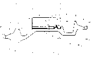
Fig. 1 schematically shown from cross-sectional plane, be used to install a non-restrictive example of the assembly that the bearing support of tire constitutes by a wheel rim and one.
The specific embodiment
Like this, according to assembly of the present invention, by can slip on the suitable wheel rim load-bearing surface, elastically deformable, constitute at the not extending tread bearing support of circumferencial direction.The first wheel rim seat of described load-bearing surface extends vertically to the inside; Its minimum diameter equals the diameter of any wheel rim part between the end of the outer end vertically of described load-bearing surface and jut or bump at least, this jut or bump have lower height, extend to the outside of the outward-dipping described first wheel rim seat vertically.When meridional plane is seen, the circle diameter at the inside end place vertically of the bus of the second wheel rim seat is bigger than the circle diameter at the inside end place vertically of the first wheel rim seat.Described two wheel rim seats extend to two truncation parts vertically to the inside.The height of this truncation part equals 0.01 times of minimum diameter of this load-bearing surface at least.The angle α of the bus of truncation part and rotation axis equals 45 at least.It is characterized in that it highly is the jut of the circumferencial direction of h that this wheel rim load-bearing surface has at least one; This jut is placed in the cell body of a circumferencial direction of leaving on the inside face radially of this tread bearing support, described jut is supported at least one sidewall of this groove vertically, and be close to this sidewall.
" minimum diameter " of this wheel rim load-bearing surface---to this diameter with the radial plane parallel, comprise in the plane of circular distal of described load-bearing surface of the most close first wheel rim seat and measured---be interpreted as being meant the ultimate range between two relative points of the diametric(al) of described circular distal.
Consider the rim size discussed and will be installed in tire size on the described wheel rim that " jut of low clearance or bump " is interpreted as being meant that it equals 2.5% jut or bump of wheel rim load-bearing surface minimum diameter highly at the most.
The axial dimension of the jut of this circumferencial direction and radial dimension are preferably less.Described 0.005-0.02 times of being of a size of wheel rim load-bearing surface diameter.The jut of described load-bearing surface can insert on this supporting inside face in the groove of same size basically, and is close to two sidewalls of this groove.
On the other hand, the groove of this bearing support circumferencial direction also can have relatively large size.So the jut of this wheel rim load-bearing surface promptly can upwards contact with a single sidewall of the groove of this circumferencial direction in week, and is close to this single sidewall.
For fear of excessive difficulty is arranged when being installed in this tread bearing support on the wheel rim load-bearing surface, in all cases, all wish the bus of bearing groove of this circumferencial direction of the most close second wheel rim seat, with the crossing end of the bus of this load-bearing surface, axial distance between the axial end of the supporting of the most close this same second wheel rim seat equals 0.3 times of axial width 1 of inside face of the radial direction of this bearing support at the most.
Equally, the interior face portion of the radial direction of this tread bearing support strengthens with the reinforcing bar that strengthens part.This enhancing part is divided into two parts: first in axial direction, in the first wheel rim seat, one side, its position directly upwards with the distance of this bearing support bottom, equal the height h of this jut at the most.Second portion is then in the second wheel rim seat, one side, and the radial distance of its position and this bearing support bottom is greater than the height h of described outshot.
Equally, carry out easily in order to make the installation of bearing support on the wheel rim load-bearing surface, the jut of load-bearing surface preferably has such cross-sectional plane, and the side of the most close first wheel rim seat on this cross-sectional plane is truncated cone.The angle β that the bus of this truncated cone and the rotation axis of this assembly form is between 15 to 45; And the side of the most close second wheel rim seat also is a truncated cone, and the bus of this truncated cone and the angle χ between the rotation axis are between 70 to 90.These two buses can connect with a circular arc or a straight line line segment.As can be seen, the border is just determined by angle beta and χ.
For tire is installed, when finishing this assembly, do not produce difficulty, the best maximum gauge of the jut of this load-bearing surface equals the diameter of the axial outer end of the second wheel rim seat at the most.
With reference to unique explanation that a Fig. 1 carried out will the present invention may be better understood.Fig. 1 schematically shown from cross-sectional plane, be used to install a non-restrictive example of the assembly that the bearing support of tire constitutes by a wheel rim and one.
Fig. 1 represents the cross-sectional plane of a single-piece rim 10 described in European patent application EP 1098779.This wheel rim can form a single-piece wheel with a disk; Perhaps, can with this wheel rim independently, produce this disk, and then this disk and described wheel rim combined.This wheel rim 10 comprise two Frusto-conical wheel rim seats 13 ' and 13 ", they have unequal diameter D respectively
A' and D
A"." diameter of truncated cone shape wheel rim seat " is meant the diameter of the round nose that it is maximum.These two seats 13 ' and 13 " bus, tilt towards the outside; It is along the diameter D of two the inners of axial direction
A' and D
A", respectively than its diameter D along two outer ends of axial direction
B' and D
B" big.Described two truncated cone shape wheel rim seats extend to two outshots or bump 15 ' and 15 at axial direction towards the outside ".When in the directional survey vertical with rotation axis, the height of these two outshots equals 5.7mm.Preparation is installed in the first wheel rim seat 13 ' of the vehicle outer side that this assembly is housed, along extending axially to the inboard of a truncated cone part 17.The bus of this truncated cone part 17 with the line that is parallel to rotation axis, forms a α angle.This angle axially be open to the inside, radial direction is then outwards at 45.When in the vertical directional survey of a rotation axis, the height of this truncated cone part 17 is 4.0mm.The axial inner ends of described bus also is the end of wheel rim load-bearing surface 11, and this wheel rim load-bearing surface 11 is positioned at vehicle outer side vertically.Described diameter is D
NLoad-bearing surface, form by two bearing areas 111 and 112 that separated by the groove 110 of first circumferencial direction.The width L of this load-bearing surface is the axial distance between these two bearing areas 111 and 112 ends of axially being separated by farthest.The most close in the axial direction second wheel rim seat 13 that will be installed in automobile inner side " end, have a jut or position block 16.This block 16 is used to avoid being placed on the tread bearing support S on the wheel rim load-bearing surface 11, moves to the inside in the axial direction.This second wheel rim seat 13 " extends flange 14 in the axial direction to the inside; This wheel rim outside wall surface in axial direction, similar to the frustoconical part 17 of above-mentioned wheel rim seat 13 ' extend out.The height of this wheel rim is 4.0mm, in other words, equates with the height of the truncated cone part 17 of the inboard of the first wheel rim seat 13 ' in axial direction.Described wheel rim 14 with position block 16, forms a mounting groove 12, and this mounting groove 12 is used for placing and is installed in the above-mentioned second wheel rim seat 13 " on tire bead.
Load-bearing surface 11 on bearing area 112 has a jut 115.When on cross-sectional plane, seeing, the triangle that is shaped as a dome of this jut; Its axially on the most close first wheel rim seat 13 ' the bus of a truncated cone on surface, with rotation axis, form one 40 ° angle beta.This angle is open laterally vertically, radially then towards the inboard.The most close vertically above-mentioned second wheel rim seat 13 of this jut " the bus on surface, with rotation axis, form one 80 ° angle χ.Described two buses are coupled together by a circular arc.Obviously, the cross-sectional plane of described jut can be difformity, particularly can be semicircle.The height h of jut 115 equals 4.5mm, that is to say, basically with jut 15 ' and 15 " height identical; And its diameter D
PThen than the second wheel rim seat 13 " axial outer end diameter D
B" little.Above-mentioned characteristic can make above-mentioned bearing support be easily mounted on the load-bearing surface of wheel rim on the one hand; On the other hand, tire is easily mounted on the described wheel rim.The shape of groove 30---this groove is formed on the lower surface radially of above-mentioned bearing support S---is identical with the shape of above-mentioned jut 115; And size is also substantially the same.In above-mentioned bearing area 112, the axial distance V between the axial end of the end of the truncated cone bus of the groove of the supporting of the most close second wheel rim seat and the supporting of the most approaching same second wheel rim seat equals 0.2 times of inner surface axial width 1 of this bearing support S.
The bottom of described supporting S is strengthened by a reinforcing steel bar 18 as not extending enhancing part.This enhancing part is made of two parts:
First 180; It the axial the most close above-mentioned first wheel rim seat 13 '.When on the load-bearing surface that above-mentioned bearing support is installed in wheel rim, this part does not pass across above-mentioned jut 115; And its axial width λ
1Than the most close first wheel rim seat 13 ' the end of end and the truncated cone shape wall that becomes β angle bevelled groove 30 with respect to rotation axis of inside face of this supporting between axial distance l
1, big a little.The reinforcement of described part 180 is positioned on this bearing support surface in radial direction; And separating the distance of 2mm with described surface, this distance is littler than the height h of groove 30.
Claims (6)
- One by the wheel rim that comprises the first and second wheel rim seats and can slip into that a corresponding wheel rim load-bearing surface (11) is gone up, assembly elastically deformable, that form at the not extending tread bearing support (S) of circumferencial direction, described load-bearing surface (11) extends this first wheel rim seat (13 '), the minimum diameter (D of this load-bearing surface vertically to the inside N) be equal at least the axial outer end of described load-bearing surface (11) and have the jut of low clearance or the end of bump (15 ') between the diameter of any wheel rim part, this jut or bump are in the outside of the outward-dipping described first wheel rim seat (13 '), extend vertically, (13 ") have a bus to the second wheel rim seat; from the cross section, the circle diameter (D at the axial inner ends place of this bus A") is greater than the inner place circle diameter (D of the axial direction of the first wheel rim seat (13 ') A'), described two wheel rim seats truncated cone part (17 that in axial direction extends internally out, 14), the height of these two truncated cone parts, at least equal 0.01 times of minimum diameter of above-mentioned load-bearing surface (11), the bus of this truncated cone part and the angle (α) of rotation axis equal 45 ° at least, described assembly is characterised in that this wheel rim load-bearing surface (11) has the jut (115) of the circumferencial direction with height (h) at least, this jut inserts in the groove (30) of a circumferencial direction of making on the inner radial surface of above-mentioned tread bearing support (S), makes described jut (115) contact and be close to at least one sidewall of this groove (30) in the axial direction.
- 2. assembly as claimed in claim 1, it is characterized in that this circumferencial direction jut axially and radial dimension all less, the described diameter (D that is of a size of the load-bearing surface (11) of this supporting N) 0.005 to 0.02 times between.
- 3. assembly as claimed in claim 1 is characterized in that the maximum gauge (D of the jut (115) of this load-bearing surface (11) P) equal the second wheel rim seat (diameter (D of the axial outer end of 13 ") at the most B").
- 4. assembly as claimed in claim 1, the jut (115) that it is characterized in that this load-bearing surface (11) comprises two sides, the side of the most close first wheel rim seat (13 ') is a truncated cone shape, the rotation axis of its bus and this assembly is formed on the angle (β) between 15 ° and 45 °, and the most close second wheel rim seat (side of 13 ") also is a truncated cone shape; the angle (χ) between the rotation axis of its bus and this assembly forms 70 ° to 90 °, and these two buses can couple together with a circular arc or a straight line line segment.
- 5. assembly as claimed in claim 1, be characterised in that (axial distance (V) between the axial end of the supporting of terminal and the most approaching this same second wheel rim seat that the bus of the bus of the groove of the circumferencial direction of 13 ") (30) and load-bearing surface (112) intersects equals 0.3 times of axial width (1) of this bearing support inner radial surface to the most close second wheel rim seat at the most.
- 6. assembly as claimed in claim 5, the inside part radially that it is characterized in that this tread bearing support (S), strengthen by not extending enhancing part reinforcing bar (18), this reinforcing bar is divided into two parts: be in the first wheel rim seat (13 ') side on first is axial, the radial distance of its position and this bearing support (S) bottom equals the height (h) of the jut of this supporting at the most, (13 ") side, the radial distance of its position and this supporting (S) bottom is greater than the height (h) of described jut (115) and second portion is positioned at the second wheel rim seat.
Applications Claiming Priority (2)
| Application Number | Priority Date | Filing Date | Title |
|---|---|---|---|
| FR00/17080 | 2000-12-22 | ||
| FR0017080A FR2818585A1 (en) | 2000-12-22 | 2000-12-22 | SET OF A RIM AND SUPPORT SUPPORT |
Publications (2)
| Publication Number | Publication Date |
|---|---|
| CN1359809A CN1359809A (en) | 2002-07-24 |
| CN1280113C true CN1280113C (en) | 2006-10-18 |
Family
ID=8858243
Family Applications (1)
| Application Number | Title | Priority Date | Filing Date |
|---|---|---|---|
| CNB011446013A Expired - Fee Related CN1280113C (en) | 2000-12-22 | 2001-12-19 | Assembly composed of rim and bearing support |
Country Status (10)
| Country | Link |
|---|---|
| US (1) | US6609549B2 (en) |
| EP (1) | EP1216850B1 (en) |
| JP (1) | JP4044335B2 (en) |
| CN (1) | CN1280113C (en) |
| AT (1) | ATE269227T1 (en) |
| BR (1) | BR0106172A (en) |
| DE (1) | DE60103843T2 (en) |
| ES (1) | ES2222303T3 (en) |
| FR (1) | FR2818585A1 (en) |
| RU (1) | RU2272715C2 (en) |
Families Citing this family (13)
| Publication number | Priority date | Publication date | Assignee | Title |
|---|---|---|---|---|
| FR2817800A1 (en) * | 2000-12-13 | 2002-06-14 | Michelin Soc Tech | WHEEL WITH RIM HAVING OUTSIDE INCLINED SEATS AND MADE BY AN EXTRUSION PROCESS |
| JP2007521170A (en) * | 2003-06-20 | 2007-08-02 | ソシエテ ドゥ テクノロジー ミシュラン | Assembly having rim and run flat support |
| WO2005068224A1 (en) * | 2003-12-19 | 2005-07-28 | Societe De Technologie Michelin | Improved rim for rum-flat tire assemblies |
| US7243694B2 (en) * | 2003-12-19 | 2007-07-17 | Michelin Recherche Et Technique S. A. | Run-flat support ring with improved mounting features |
| DE60333045D1 (en) * | 2003-12-19 | 2010-07-29 | Michelin Soc Tech | RUN-FLAT SUPPORT RING WITH IMPROVED FASTENING FEATURES |
| US7104302B2 (en) | 2004-06-08 | 2006-09-12 | Michelin Recherche Et Technique S.A. | Run-flat support ring with internal fin |
| US7047800B2 (en) | 2004-06-10 | 2006-05-23 | Michelin Recherche Et Technique S.A. | Piezoelectric ceramic fibers having metallic cores |
| US7730918B2 (en) * | 2006-04-21 | 2010-06-08 | Michelin Recherche Et Technique S.A. | Vehicle rim intended for mounting a tire and a bearing support and mounting process for a tire/wheel assembly provided with such a rim |
| WO2019002794A1 (en) * | 2017-06-30 | 2019-01-03 | Compagnie Generale Des Etablissements Michelin | Wheel rim with reduced-height rim flange |
| WO2019002792A1 (en) | 2017-06-30 | 2019-01-03 | Compagnie Generale Des Etablissements Michelin | Rolling assembly having a rim, the flange of which forms a support of increased axial width |
| FR3082147B1 (en) * | 2018-06-08 | 2021-05-28 | Michelin & Cie | RIM SET AND FLEXIBLE EXTENSIONER FOR ROLLER SET |
| RU2749143C1 (en) * | 2019-09-13 | 2021-06-07 | Игорь Венедиктович Балабин | Design of wheel with pneumatic tire for working on mobile machine with large camber |
| CN114056012B (en) * | 2020-08-10 | 2024-02-27 | 摩登汽车有限公司 | Tyre supporting device for preventing automobile tyre from rapid air leakage |
Family Cites Families (15)
| Publication number | Priority date | Publication date | Assignee | Title |
|---|---|---|---|---|
| US4248286A (en) * | 1978-06-30 | 1981-02-03 | The Goodyear Tire & Rubber Company | Safety support assembly for pneumatic tires |
| FR2699121B1 (en) | 1992-12-11 | 1995-03-17 | Michelin & Cie | Set formed by a tire, a rim and a support ring. |
| FR2698823B1 (en) * | 1992-12-03 | 1995-02-17 | Hutchinson | Improved ring device for run flat. |
| FR2713558B1 (en) * | 1993-12-08 | 1996-03-01 | Michelin & Cie | Pneumatic, rim, support ring and assembly comprising said elements. |
| FR2713557B1 (en) * | 1993-12-08 | 1996-03-01 | Michelin & Cie | Rim, support ring and assembly comprising said elements. |
| FR2719258B1 (en) * | 1994-04-27 | 1996-07-19 | Hutchinson | Flat running device for motor vehicle. |
| FR2746347A1 (en) * | 1996-03-19 | 1997-09-26 | Michelin & Cie | SAFETY SUPPORT IN FLEXIBLE ELASTOMERIC MATERIAL FOR TIRES |
| FR2748695B1 (en) * | 1996-05-15 | 1998-06-26 | Michelin & Cie | WHEEL WITH RIM HAVING OUTSIDE INCLINED SEATS |
| FR2776963B1 (en) * | 1998-04-06 | 2000-06-16 | Hutchinson | FLAT ROLLING DEVICE FOR MOTOR VEHICLE AND MOUNTING METHOD THEREOF |
| FR2770459B1 (en) * | 1997-10-30 | 2000-01-14 | Hutchinson | FLAT ROLLING DEVICE FOR A MOTOR VEHICLE |
| FR2781184A1 (en) | 1998-07-20 | 2000-01-21 | Michelin Rech Tech | Wheel rim for carrying tires, with tire seats inclined outwards from the center of the rim |
| ES2214794T3 (en) | 1998-11-12 | 2004-09-16 | Societe De Technologie Michelin | SAFETY SUPPORT FOR INJECTABLE ELASTOMERO MATERIAL FOR TIRE. |
| FR2794686B1 (en) | 1999-06-10 | 2001-08-10 | Michelin Soc Tech | LIGHT SAFETY SUPPORT FOR TIRES |
| FR2797224B1 (en) | 1999-08-02 | 2002-02-08 | Michelin Soc Tech | SET OF A RIM AND SUPPORT SUPPORT |
| FR2800671A1 (en) * | 1999-11-04 | 2001-05-11 | Michelin Soc Tech | RIM FOR RECEIVING A SUPPORT RING |
-
2000
- 2000-12-22 FR FR0017080A patent/FR2818585A1/en active Pending
-
2001
- 2001-11-29 DE DE60103843T patent/DE60103843T2/en not_active Expired - Lifetime
- 2001-11-29 ES ES01128299T patent/ES2222303T3/en not_active Expired - Lifetime
- 2001-11-29 EP EP01128299A patent/EP1216850B1/en not_active Expired - Lifetime
- 2001-11-29 AT AT01128299T patent/ATE269227T1/en not_active IP Right Cessation
- 2001-12-19 CN CNB011446013A patent/CN1280113C/en not_active Expired - Fee Related
- 2001-12-20 RU RU2001135185/11A patent/RU2272715C2/en not_active IP Right Cessation
- 2001-12-20 BR BR0106172-0A patent/BR0106172A/en active Search and Examination
- 2001-12-20 US US10/034,104 patent/US6609549B2/en not_active Expired - Fee Related
- 2001-12-21 JP JP2001402931A patent/JP4044335B2/en not_active Expired - Fee Related
Also Published As
| Publication number | Publication date |
|---|---|
| EP1216850A1 (en) | 2002-06-26 |
| BR0106172A (en) | 2002-08-13 |
| JP4044335B2 (en) | 2008-02-06 |
| DE60103843D1 (en) | 2004-07-22 |
| EP1216850B1 (en) | 2004-06-16 |
| DE60103843T2 (en) | 2005-06-23 |
| ES2222303T3 (en) | 2005-02-01 |
| FR2818585A1 (en) | 2002-06-28 |
| US6609549B2 (en) | 2003-08-26 |
| RU2272715C2 (en) | 2006-03-27 |
| JP2002326503A (en) | 2002-11-12 |
| CN1359809A (en) | 2002-07-24 |
| US20020124923A1 (en) | 2002-09-12 |
| ATE269227T1 (en) | 2004-07-15 |
Similar Documents
| Publication | Publication Date | Title |
|---|---|---|
| CN1280113C (en) | Assembly composed of rim and bearing support | |
| CN1163365C (en) | Rim capable of supplying supporting ring on it | |
| CN1085593C (en) | Tyre rim, support ring and assembly comprising same | |
| CN1038568C (en) | Tyre, rimmer, circular supporting frame and assembly including same | |
| US6705368B2 (en) | Emergency support member | |
| CN1165094A (en) | Wheel with rim having seats inclined towards the outside | |
| EP2881267B1 (en) | A tire comprising a tread with asymmetric groove profiles | |
| USRE34909E (en) | Wheel for a track laying vehicle | |
| CN1231366C (en) | Tyre with improved bead structure | |
| CN1486252A (en) | Method for mounting a tyre on a rim | |
| CN1273315C (en) | Tyre with non symmetrical reinforced sidewalls | |
| JPS6124601A (en) | Rim of single body structure | |
| CN103298624A (en) | Vehicle wheel for commercial vehicles | |
| CN1251892C (en) | Rim and such a rim assembly with supporting seat | |
| US20230052941A1 (en) | A rim for a vehicle wheel and vehicle wheel herewith | |
| US20080210357A1 (en) | Vehicle Wheel Rim Designed For Mounting A Tyre And A Support | |
| CN115720552A (en) | Wheel structure | |
| JP2002528332A (en) | Tire and rim assembly | |
| WO2021113895A1 (en) | Improvements relating to wheels for pneumatic tyres | |
| EP1230099B1 (en) | Wheel rim | |
| CN110605941B (en) | Bead reinforcing device for pneumatic tire | |
| RU2798383C2 (en) | Structure of a wheel rim for automobile vehicles | |
| CN117341385A (en) | Rim, hub and wheel | |
| AU758547B2 (en) | Wheel rim | |
| JP2007168737A (en) | Rim for vehicle |
Legal Events
| Date | Code | Title | Description |
|---|---|---|---|
| C06 | Publication | ||
| PB01 | Publication | ||
| C10 | Entry into substantive examination | ||
| SE01 | Entry into force of request for substantive examination | ||
| C14 | Grant of patent or utility model | ||
| GR01 | Patent grant | ||
| C17 | Cessation of patent right | ||
| CF01 | Termination of patent right due to non-payment of annual fee |
Granted publication date: 20061018 Termination date: 20100119 |