CN1272183C - Sheet afterfprocessing device and image forming device with said device - Google Patents
Sheet afterfprocessing device and image forming device with said device Download PDFInfo
- Publication number
- CN1272183C CN1272183C CNB031307442A CN03130744A CN1272183C CN 1272183 C CN1272183 C CN 1272183C CN B031307442 A CNB031307442 A CN B031307442A CN 03130744 A CN03130744 A CN 03130744A CN 1272183 C CN1272183 C CN 1272183C
- Authority
- CN
- China
- Prior art keywords
- sheet material
- binding needle
- sheet
- processing apparatus
- lower jaw
- Prior art date
- Legal status (The legal status is an assumption and is not a legal conclusion. Google has not performed a legal analysis and makes no representation as to the accuracy of the status listed.)
- Expired - Fee Related
Links
Images


Classifications
-
- G—PHYSICS
- G03—PHOTOGRAPHY; CINEMATOGRAPHY; ANALOGOUS TECHNIQUES USING WAVES OTHER THAN OPTICAL WAVES; ELECTROGRAPHY; HOLOGRAPHY
- G03G—ELECTROGRAPHY; ELECTROPHOTOGRAPHY; MAGNETOGRAPHY
- G03G15/00—Apparatus for electrographic processes using a charge pattern
-
- B—PERFORMING OPERATIONS; TRANSPORTING
- B27—WORKING OR PRESERVING WOOD OR SIMILAR MATERIAL; NAILING OR STAPLING MACHINES IN GENERAL
- B27F—DOVETAILED WORK; TENONS; SLOTTING MACHINES FOR WOOD OR SIMILAR MATERIAL; NAILING OR STAPLING MACHINES
- B27F7/00—Nailing or stapling; Nailed or stapled work
- B27F7/17—Stapling machines
- B27F7/19—Stapling machines with provision for bending the ends of the staples on to the work
-
- B—PERFORMING OPERATIONS; TRANSPORTING
- B42—BOOKBINDING; ALBUMS; FILES; SPECIAL PRINTED MATTER
- B42C—BOOKBINDING
- B42C1/00—Collating or gathering sheets combined with processes for permanently attaching together sheets or signatures or for interposing inserts
- B42C1/12—Machines for both collating or gathering and permanently attaching together the sheets or signatures
-
- B—PERFORMING OPERATIONS; TRANSPORTING
- B65—CONVEYING; PACKING; STORING; HANDLING THIN OR FILAMENTARY MATERIAL
- B65H—HANDLING THIN OR FILAMENTARY MATERIAL, e.g. SHEETS, WEBS, CABLES
- B65H29/00—Delivering or advancing articles from machines; Advancing articles to or into piles
- B65H29/52—Stationary guides or smoothers
-
- B—PERFORMING OPERATIONS; TRANSPORTING
- B65—CONVEYING; PACKING; STORING; HANDLING THIN OR FILAMENTARY MATERIAL
- B65H—HANDLING THIN OR FILAMENTARY MATERIAL, e.g. SHEETS, WEBS, CABLES
- B65H2408/00—Specific machines
- B65H2408/10—Specific machines for handling sheet(s)
- B65H2408/12—Specific machines for handling sheet(s) stapler arrangement
-
- B—PERFORMING OPERATIONS; TRANSPORTING
- B65—CONVEYING; PACKING; STORING; HANDLING THIN OR FILAMENTARY MATERIAL
- B65H—HANDLING THIN OR FILAMENTARY MATERIAL, e.g. SHEETS, WEBS, CABLES
- B65H2701/00—Handled material; Storage means
- B65H2701/10—Handled articles or webs
- B65H2701/17—Nature of material
- B65H2701/176—Cardboard
Abstract
A sheet after-treatment device equipped with a stapler main body which staples sheets fed between upper and lower jaws in an opened state with a staple by closing the upper and lower jaws, and a holder for holding the stapler main body, in which a sheet transport guide surface of an upstream-side portion of the holder and the lower jaw of the stapler main body are arranged in the area where the sheets are transported, and the sheet transport guide surface of the upstream-side portion of the stapler main body is situated above the lower jaw.
Description
Technical field
The present invention relates to sheet material is carried out the sheet post-processing apparatus of post processing and is the image processing system of one of inscape with this sheet post-processing apparatus.Particularly about sheet material being carried the sheet post-processing apparatus of not damaged, miniaturization and being had the image processing system of this device.
Background technology
In the prior art, sheet post-processing apparatus for example as one of inscape of image processing system, is located at the device body of image processing system, and the sheet material of sending from device body that forms image is carried out post processing.Image processing system is to form image on sheet material.Image processing system has duplicator, printing machine, facsimile machine and their compounding machine etc.Sheet material forms image in the above by image processing system.Sheet material, common paper is arranged, as resin-made membrane, ground paper, the postcard of the substitute of common paper, seal, the overhead projector with paper etc.
In the prior art, be equipped on the sheet post-processing apparatus on the device body of image processing system, for example, each end that forms many sheet materials behind the image integrated, bind the post processing of (nailing) etc.
Formation is as shown in Figure 10 arranged in the sheet post-processing apparatus.The sheet material throughput direction that this sheet post-processing apparatus 1000 has the middle constructional surface 1002 piled up to 1003, with the sheet material fasciculation of discharging as the discharge roller of sheet material outlet and a relative arrow E is disposed at the binder 1001 of an opposite side etc.From discharging roller to 1003 sheet materials of discharging, on middle constructional surface 1002, pile up, peristome 1001a towards binder 1001 carries along arrow F directional steering, will integrate with the end of sheet material throughput direction crisscross (width) and the end of sheet material throughput direction.And enter peristome 1001a..Then, with the sheet material SB of fasciculation,, in Figure 10, discharge to left by binder 1001 bookbindings.
In addition, in sheet post-processing apparatus, such formation among Figure 11 A~Figure 11 C is arranged also.This sheet post-processing apparatus 1010 shown in Figure 11 A, for not hindering the conveying of the sheet material of carrying to arrow Q direction, is carried the position of keeping out of the way out the road and binder 1011 is equipped on from sheet material.
But, preceding a kind of existing sheet post-processing apparatus 1000 is in Figure 10, in case with after the direction conveying of sheet material by arrow E, owing to will carry, middle constructional surface 1002 and binder 1001 must be disposed at from discharging roller to 1003 positions that fall a step along arrow F directional steering.Therefore, preceding a kind of sheet post-processing apparatus 1000 must occupy unnecessary space at above-below direction, highly increases, and the problem of maximization is arranged.
In addition, a kind of existing sheet post-processing apparatus 1010 in back, owing to must carry out the integration of sheet material throughput direction by being connected to the opposite side of sheet material throughput direction along the sheet material (Figure 11 B) that arrow J direction is carried, in addition, must move to the peristome (Figure 11 C) of binder 1011 from the sheet material transfer position to the arrow G direction, there is the problem that whole device is maximized in accumulation portion in the middle of must widening.And the sheet material that bookbinding is got up will be carried along the direction of arrow Q.
Moreover these existing sheet post-processing apparatus 1000,1010 fall from binder because the sky of binder 1001,1011 such as plays at the useless pin that is produced, and make Sub-assembly Dept's risk of short-circuits.Therefore, must be at the recovery groove that its useless pin of recovery nearby is set of binder 1001,1011.But, as establish the recovery groove, and this also will occupy unnecessary space, and this also just makes whole device maximize, and increases cost.
Summary of the invention
Purpose of the present invention promptly is to provide sheet post-processing apparatus conveying, miniaturization that does not damage sheet material.
The present invention also aims to provide hardly must take up space more, the sheet post-processing apparatus of recyclable useless pin.
Purpose of the present invention is to be provided at the image processing system that device body is equipped with above-mentioned sheet post-processing apparatus again.
According to sheet post-processing apparatus of the present invention, it is characterized in that comprise: be provided with the binder mechanism of maxilla and lower jaw, the closed action of described binder mechanism by maxilla and lower jaw will be sent into sheet stitching between described maxilla and the lower jaw by binding needle; The maintaining body that keeps described binder mechanism; And the binding needle delay portion that is detained the binding needle that damages by described binder mechanism bookbinding sheet material; Described binding needle delay portion is formed by the sidepiece and the described lower jaw of described maintaining body.
According to image processing system of the present invention, it is characterized in that having: on sheet material, form the image formation department of image and the sheet post-processing apparatus that the sheet material enforcement that is formed image by described image formation department is handled; Described sheet post-processing apparatus comprises: be provided with the binder mechanism of maxilla and lower jaw, the closed action of described binder mechanism by maxilla and lower jaw will be sent into sheet stitching between described maxilla and the lower jaw by binding needle; The maintaining body that keeps described binder mechanism; And the binding needle delay portion that is detained the binding needle that damages by described binder mechanism bookbinding sheet material; Described binding needle delay portion is formed by the sidepiece and the described lower jaw of described maintaining body.
For achieving the above object, sheet post-processing apparatus of the present invention has binding apparatus and holding device; Described binding apparatus will be sent into the maxilla of open mode and the sheet material between lower jaw, be bound by binding needle when maxilla and lower jaw are closed; Holding device is used to keep binding apparatus.The lower jaw of the upstream portion of holding device upper end and binding apparatus is equipped on the zone of feeding sheets, and holding device year the upstream portion upper end be positioned at the top of the height of lower jaw.
Sheet post-processing apparatus of the present invention has the sheet material integrating apparatus, is used for the sheet material end of the direction of intersecting with the sheet material throughput direction is integrated, and this sheet material is positioned the sheet stitching position.
Sheet post-processing apparatus of the present invention, lower jaw are fixed and give prominence to binding needle, and the relative lower jaw of maxilla connects from, bending binding needle.
Sheet post-processing apparatus of the present invention has the sheet material guide part that in the upstream sheet material is led by holding device; With the upstream portion of sheet material guide part, holding device and lower jaw set for: upstream portion upper end and lower jaw by sheet material guide part, holding device reduce successively.
Sheet post-processing apparatus of the present invention, have by holding device in the upstream sheet material guide part to sheet material guiding, and the downstream sidepiece of the upstream portion of sheet material guide part, holding device, lower jaw, holding device is configured to: press reduction successively on the downstream sidepiece of upstream portion upper end, lower jaw, holding device of sheet material guide part, holding device.
Sheet post-processing apparatus of the present invention, the upstream portion upper end of holding device becomes the guide part to the sheet material guiding of being carried.
Sheet post-processing apparatus of the present invention in the upstream side sidepiece of holding device and the zone that forms above the lower jaw, is to store binding needle that the bookbinding sheet material damages let the acupuncture needle remain at a certain point portion.
Sheet post-processing apparatus of the present invention, between the upstream portion of binding apparatus and holding device and between the sidepiece of the downstream of binding apparatus and holding device, at least between the upstream portion of binding apparatus and holding device, has the gap of taking in the binding needle that the bookbinding sheet material damages in the two.
Sheet post-processing apparatus of the present invention has the gap of taking in the binding needle that the bookbinding sheet material damages at the upstream side of holding device.
Sheet post-processing apparatus of the present invention, gap have the inclined guide surface of the binding needle guiding that the bookbinding sheet material is damaged.
Sheet post-processing apparatus of the present invention, binding apparatus and holding device, the upstream side inclination step-down of sheet material throughput direction.
Sheet post-processing apparatus of the present invention, binding apparatus and holding device are equipped to movable, so that the peristome of maxilla and lower jaw reveals to the outside.
Sheet post-processing apparatus of the present invention, binding apparatus and holding device are equipped to and can turn to upstream side from the downstream of sheet material throughput direction, so that the peristome of maxilla and lower jaw can reveal to the outside.
For achieving the above object, image processing system of the present invention has the image processing system that forms image on sheet material, the sheet post-processing apparatus that gets up with the sheet stitching that is used for forming image; Sheet post-processing apparatus promptly is above-mentioned sheet post-processing apparatus.
Sheet post-processing apparatus of the present invention can set the peristome of bookbinding machine part 208 in the sheet material conveyor zones, can cheapness and miniaturization.
Sheet post-processing apparatus of the present invention can reclaim the empty useless pin of beating or causing because of binder is bad of binder, so can avoid Sub-assembly Dept's risk of short-circuits.
Image processing system of the present invention can cheapness and the sheet post-processing apparatus of miniaturization owing to have, the miniaturization so also can make its cheapness.
Image processing system of the present invention owing to have the above-mentioned sheet post-processing apparatus of the danger that can avoid Sub-assembly Dept's short circuit etc., can prevent the damage to installing.
Description of drawings
Fig. 1 is with the sheet post-processing apparatus of first embodiment of the invention, to be loaded on the profile of the printing machine on device body top as one of inscape of the printing machine of image processing system.
Fig. 2 is the profile that the integral body of the summary sheet post-processing apparatus of representing first embodiment of the invention constitutes.
Fig. 3 A is the exploded view of the bookbinding machine part of first embodiment of the invention.
Fig. 3 B is the figure from the bookbinding machine part of right side 3A with the aid of pictures.
Fig. 4 A sees the binder of first embodiment of the invention and the figure of the incorporate bookbinding machine part of retainer from sheet material throughput direction upstream side.
Fig. 4 B is the figure from the bookbinding machine part of right side 4A with the aid of pictures.
Fig. 5 A, 5B, 5C, 5D are the figure of the configuration relation of the conveyor zones of the sheet material carried in the sheet post-processing apparatus of expression first embodiment of the invention and bookbinding machine part.
Fig. 5 A is the figure at the state of sheet material conveyor zones during along arrow M direction feeding sheets.
Fig. 5 B is the figure of expression sheet material by the state of binder body openings portion.
Fig. 5 C be expression along the reverse feeding sheets of arrow N direction, be connected to the figure that carries the block state.
Fig. 5 D is that sheet bundle moves along arrow R direction, sends into the figure of the state of bookbinding machine part.
Fig. 6 is the profile that the integral body of the summary sheet post-processing apparatus of representing first embodiment of the invention constitutes.
Fig. 7 A is the front view at the binding part of the sheet post-processing apparatus of third embodiment of the invention.
Fig. 7 B is the VIIB-VIIB cutaway view of Fig. 7 A.
Fig. 8 is the stereogram of the bookbinding machine part of first embodiment of the invention.
Fig. 9 rotates bookbinding machine part from the state of Fig. 8, the figure of the state that the peristome that makes the binder body manifests to the outside.
Figure 10 is the skeleton diagram of the sheet post-processing apparatus of conventional example.
Figure 11 A, Figure 11 B, Figure 11 C are the general views of other existing sheet post-processing apparatus.
Figure 11 A is the figure of input sheet material state.
Figure 11 B is the figure of reverse feeding sheets state.
Figure 11 C is the figure that sheet material is sent into the binder state.
The specific embodiment
Following sheet post-processing apparatus and the image processing system of borrowing figure explanation embodiments of the invention.
Sheet post-processing apparatus for example as one of inscape of image processing system, is located at the device body of image processing system, and the sheet material of sending from device body that forms image is carried out post processing.Image processing system is used for forming image on sheet material.In the image processing system, duplicator, printing machine, facsimile machine and their compounding machine etc. are arranged.The sheet material processing apparatus of present embodiment, being equipped on as one of inscape of printing machine for example is on the printing machine of representative with the laser beam printer.Sheet material processing apparatus not only is located at printing machine.
On sheet material, form image by image processing system.In the sheet material, common paper is arranged, as resinous film, ground paper, the postcard of the substitute of common paper, seal, paper that the overhead projector is used etc.
[printing machine]
In Fig. 1, in printing machine 300, the sheet post-processing apparatus 200 of first embodiment is loaded on the top of the device body 301 of printing machine 300 as one of inscape of printing machine 300.And, sheet post-processing apparatus 200 that also can first embodiment on printing machine, and load onto the sheet post-processing apparatus of other embodiment.
In the feeding box 302 of the bottom of being located at printing machine body 301, piling up many sheet material S.These many sheet material S by various rollers, separate one by one successively and are fed into for example image forming part 303 as image processing system from the sheet material of upper.Sheet material S from 302 feedings of feeding box, in printing machine body 301,, form program by the image of so-called laser beam mode based on the printing information of the regulation of supplying with from computer or network, image forming part 303 forming toner image runs off toner image on sheet material.And, when sheet material is sent into image forming part 303, in the photosensitive drum body 304 of image forming part 303,, form toner image by the toner in the box 305.
Next, by 306 pairs of sheet material heating of fuser pressurization in downstream, with the permanent photographic fixing of toner image.To the sheet material S after the image fixing, the position of the plate 307 of the printing machine body 301 that switches by the control information that comes based on not shown control part, be discharged to the discharge portion 308 of being located at printing machine body 301 tops, or be discharged on the stacked tray 204 of sheet post-processing apparatus 200.
(sheet post-processing apparatus of first embodiment)
Sheet post-processing apparatus 200 is accepted to be discharged to sheet material machine outside from printing machine body 301, complies with simple accumulation mode and post processing pattern sheet material is handled.
As select simple accumulation mode, sheet post-processing apparatus 200, by the inlet roller to 201, mediate roller to 202, row's paper roller is to 203 feeding sheets, and it is piled up in stacked tray 204.
As select the post processing pattern, in sheet post-processing apparatus 200, the row's of making paper roller leaves from lower roller 203b 203 last roller 203a, by the inlet roller to 201, mediate roller is to the 202 top feeding sheets by block 310; Even in case in middle accumulation portion 205 many its fasciculations of heap, in sheet post-processing apparatus 200, throughput direction integral piece 206 is rotated to clockwise direction from position shown in Figure 1, sheet bundle counter delivering on middle accumulation portion 205 is connected to block 310, limits the end of sheet material throughput direction; And integrate by 207 pairs of crisscross (sheet width directions) of for example horizontal integration portion with the sheet material throughput direction as the sheet material integrating apparatus.Then, sheet post-processing apparatus 200,1-11 binds processing by bookbinding machine part; Crimping row paper roller is discharged to stacked tray 204 to 203 with sheet bundle again.Sheet 206 is that rotate at the center with axle 227.On axle 227, be provided with bar 228, and roller 203a be set free to rotately at bar 228 leading sections.Bar 228 is energized by spring 229 last roller 203a is crimped on the lower roller 203b.
Fig. 3 A and Fig. 3 B are the exploded views of the formation of expression bookbinding machine part H1.Bookbinding machine part H1 has binder body 208, case shape keeper 211,212 and binder box C etc.Binder body 208 has maxilla 209 and lower jaw 210.Maxilla 209 is opened with lower jaw 210 and is formed peristome 220.Binder body 208 runs through the sheet material that enters peristome 220 from fixing lower jaw 210 outstanding binding needles.Maxilla 209 is moved, bending binding needle, bookbinding sheet bundle downwards.
Retainer 211,212 is fixed in the body 221 of sheet post-processing apparatus 200 from upper and lower clamping binder body 208.Binder box C can be located at binder body 208 with freely installing and removing.Be used to take in not shown binding needle.
Fig. 4 A and Fig. 4 B are the figure of the bookbinding machine part H1 of combined binding machine body 208 and retainer 211,212 formation.On retainer 211,212, integrally formed sheet material is carried spigot surface 213,214.Sheet material is carried spigot surface 213,214, the sheet material S that enters is imported the peristome 220 of binder body 208.
Fig. 2 is the formation of expression bookbinding machine part H1 and the summary section of periphery thereof.Binder body 208 is disposed by the relative vertical direction cant angle theta of the upstream side angle of retainer 211,212 at the sheet material throughput direction.That is, bookbinding machine part H1, the upstream side of sheet material throughput direction tilts to lower.
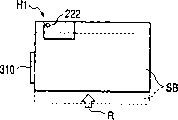
As the holding device shape of downside retainer 212 for example, the throughput direction upstream side, be the sidewall 212a of sheet material approach axis, as stipulating: height=T1 of the top 210a of the lower jaw 210 of height (sheet material is carried the height of spigot surface 214) the binder body 208 of the sidewall 212a that uses paper approach axis side of retainer 212, then T1 〉=0.By the way, T1 is the roughly thickness of pin.In Fig. 2, in order to see the step of T1 clearly, and exaggeration this step that drawn.
In addition, the formation as complying with in bookbinding machine part H1 inside, has formed for example bag portion 215 as pin delay portion.This bag portion 215 is the parts of taking in the useless pin of pin that the bookbinding sheet material damages etc.Tilt to lower because bookbinding machine part H1 is the upstream side of sheet material throughput direction, so the reliable side of useless pin that is stranded in bag portion 215 is detained, it is also easy to remove this useless pin.And, even being the upstream side of sheet material throughput direction, bookbinding machine part H1 do not tilt to lower.Also useless pin can be stranded in the bag 215.Because useless pin is stranded in bag portion 215, make Sub-assembly Dept's short circuit so can prevent that useless pin from falling from binder.
Fig. 5 A, 5B, 5C and 5D are the planes of the configuration relation of the conveyor zones SA of the sheet material S that carried of expression and bookbinding machine part H1.The peristome 220 overlapping conveyor zones SA that are present in sheet material S of bookbinding machine part H1.That is, carry the top 210a of spigot surface 214 (with reference to Fig. 2) and lower jaw 210 to be arranged in sheet material conveyor zones SA as the sheet material with the upper end of the sidewall 212a of paper approach axis side of retainer 212.
Shown in Fig. 5 A, at the sheet material S of sheet material conveyor zones SA along the conveying of arrow M direction, shown in Fig. 5 B, peristome 220 by binder body 208 and be piled up in the middle of accumulation portion 205, then, sheet material by shown in throughput direction integral piece 206, the image pattern 5C like that along counter the giving of arrow N direction, be connected to and carry block 310 (with reference to Fig. 1).When each feeding sheets, carry out above these actions.
And when sending first sheet material along arrow N direction is counter, sheet material is carried guide plate 214, is connected to block 310 by sheet material; But, be not hung on sheet material conveying spigot surface 214 so can not collude because the height of middle accumulation portion 205 and sheet material carry spigot surface 214 roughly on one side.Second later sheet material be not owing to first counter sending of sheet material upper edge arrow N, can collude the lacing film material yet and carry spigot surface 214.
In case heap regulation number sheet material S in middle accumulation portion 205, its sheet bundle SB is integrated by 207 pairs of widths of horizontal integration portion; Shown in Fig. 5 D, make it move to the sheet stitching position simultaneously along arrow R direction.Then, sheet bundle is in its sheet stitching position, and the maxilla 209 of binder body 208 descends, and is bound by maxilla 209 and lower jaw 210.
And, in above action, sheet material is moved along arrow R direction, but its amount of movement, with Figure 11 C of conventional example in when the displacement of arrow G direction is compared, the part that sheet material is introduced into the peristome 220 of binder in advance in Fig. 5 C will be lacked.Therefore, this short part, the area of accumulation portion 205 becomes narrow in the middle of can making, and can make sheet post-processing apparatus 200 miniaturizations.
In addition, the sheet post-processing apparatus 100 of present embodiment is that sheet bundle SB moves and binds in the sheet stitching position along arrow R direction in Fig. 5 D; But can not move, from promptly binding at first at gutter pos along arrow R direction yet.That is, in Fig. 5 A, make sheet material S pass through the sheet stitching position, then move, stop in the sheet stitching position along arrow N direction along arrow M direction.Sheet material is moved, at this moment integrate by 207 pairs of widths of horizontal integration portion.Thereby, in such action, compare with situation about moving along the arrow G direction shown in Figure 11 C of conventional example, do not need to move along the arrow G direction, in the middle of can making the area stenosis of accumulation portion 205 narrow, can make sheet post-processing apparatus 200 miniaturizations.
(sheet post-processing apparatus of second embodiment)
Bottom borrows Fig. 6 that the sheet post-processing apparatus 250 of second embodiment is described.In the sheet post-processing apparatus 250 of second embodiment, the part for identical with the sheet post-processing apparatus 200 of first embodiment gives identical symbol, omits the explanation of this part.The sheet post-processing apparatus 250 of second embodiment is compared with the sheet post-processing apparatus 200 of first embodiment, the shape difference of the retainer 251,252 of the case shape of bookbinding machine part H2.
Fig. 6 is the summary section of the formation of the formation of expression bookbinding machine part H2 and periphery thereof.This bookbinding machine part H2 also has binder body 208, retainer 251,252 and not shown binder box etc.On retainer 251,252, integrally formed sheet material is carried spigot surface 253,254.Sheet material carries spigot surface 253,254 the sheet material S that is entered to be imported the peristome 220 of binder body 208.
As by bookbinding machine part H2, to be in the conveying road surface 255 of throughput direction upstream side and as the relation of the height (sheet material is carried the height of spigot surface 254) of the sidewall 252a of the sheet material approach axis side of for example retainer 252 of holding device, be defined as: height=T2 of the sidewall 252a of the sheet material approach axis side of height one retainer 252 on conveying road surface 255, then set T2 〉=0.
In addition, the shape of downside retainer 252, the throughput direction upstream side, be the sidewall 252a of sheet material approach axis side, be defined as: height=T3 of the top 210a of the lower jaw 210 of the height of the sidewall 252a of the sheet material approach axis side of retainer 252 (sheet material is carried the height of spigot surface 254)-binder body 208, then T3 〉=0.By the way, T3 is the roughly thickness 0.5mm of pin.In addition, in Fig. 6, the step of T3, for this step is described, exaggeration is drawn.
Moreover, the relation of the height of the top 210a of the height of the sidewall 252b of the sheet material discharge direction side of retainer 252 and the lower jaw 210 of binder body 208, as regulation: height one retainer 252 of the top 210a of the lower jaw 210 of binder body 208 discharge height=T4 of upper end 252ba of the sidewall 252a of direction side with paper, then set T4 〉=0.
Like this, sheet post-processing apparatus 250, because along for example conveying road surface 255 as the sheet material guide part, as for example sheet material of the upstream portion of holding device upper end carry spigot surface 254, lower jaw 210 top 210a, it reduces highly successively as the upper end 252b of the sidewall 252a of the downstream sidepiece of holding device, so feeding sheets sleekly.
Between the sheet material throughput direction upstream side of binder body 208 and retainer 251,252, formed its first wideer than the thickness of pin at interval gap 216.This first gap 216, the recyclable useless pin that this falls when useless pin falls.By the way, the interval in first gap 216 is roughly greater than 0.5mm.And this first gap 216 may not be formed at 251 of binder body 208 and retainers.
In addition, between the downstream and bookbinding machine part H2 of carrying road surface 255, formed same its second wideer than the thickness of pin at interval gap 217.This second gap 217 is used for being recovered in the useless pin that does not reclaim in first gap 216.
Besides, between the downstream of the throughput direction of binder body 208 and retainer 251,252, form its wideer than the thickness of pin at interval third space 219.This third space 219 also is the recyclable useless pin that this falls when useless pin falls.By the way, the interval of third space 219 is greater than 0.5mm.And this third space 219 may not be in binder body 208 and 251 formation of retainer.
(sheet post-processing apparatus of the 3rd embodiment)
Bottom illustrates the sheet post-processing apparatus of the 3rd embodiment.The sheet post-processing apparatus of the 3rd embodiment is compared with the sheet post-processing apparatus of first embodiment, the shape difference of bookbinding machine part H3.Thereby, in Fig. 7 A and Fig. 7 B, bookbinding machine part H3 only is described, and omits explanation other formations.
Fig. 7 A and Fig. 7 B are the skeleton diagrams of the formation of expression bookbinding machine part H3.This bookbinding machine part H3 also has binder body 208, case shape retainer 271,272 and binder box C etc.Binder body 208 and as 272 of for example retainers of holding device is provided with four gap 218 suitable with the gap 216,219 of the bookbinding machine part H2 of the second embodiment sheet post-processing apparatus.In Fig. 7 B, represented to be equivalent to the 4th gap 218 in gap 216.The width in the 4th gap 218 is also set thick widelyer than the pin of binding needle.In the 4th gap 218, formed for example inclined plane 218a as spigot surface.On the retainer 272 of the lower end of inclined plane 218a, be formed for discharging the outlet 273 of useless pin.
Thereby, fall into the useless pin in the 4th gap 218, can glide along the inclined plane 218a in the 4th gap 218, be discharged to the device outside from outlet 273.Outlet 273 is formed at the position that does not dispose Sub-assembly Dept.In addition, having under the situation of Sub-assembly Dept below the outlet 273, be preferably in and establish the lid that freely to install and remove on the outlet.
The bookbinding machine part H3 of present embodiment also can be as above-mentioned bookbinding machine part H1, the H2 upstream side cant angle theta degree configuration at the sheet material throughput direction.
As shown in Figure 9, above-mentioned bookbinding machine part H1, H2, H3, upstream side is rotated from the downstream of sheet material throughput direction, the peristome 220 of binder body 208 is opened wide to the outside be located at (with reference to Fig. 1 and Fig. 8) on the sheet post-processing apparatus body 221 like that.Under the situation of bookbinding machine part H1, as shown in Figure 2, be arranged on the sheet post-processing apparatus body 221 by bolster 222,223.Equally, under the situation of bookbinding machine part H2, as shown in Figure 6, be arranged on the sheet post-processing apparatus body 221 by bolster 224,225.The bolster of bookbinding machine part H3, diagram has been omitted.And above-mentioned bookbinding machine part H1, H2, H3 also may not rotate, and also can fix.
The sheet post-processing apparatus 200 of first embodiment of the invention discussed above, be connected in the device body 301 of printing machine 300 as one of inscape of printing machine 300, bookbinding machine part H1 with the sheet material that is used to bind many fasciculations of discharging from device body 301, owing to will form retainer 211,212 (these retainers 211,212 keep for example binder body 208 of binding apparatus) the height setting of sidewall 212a of sheet material approach axis side of opening must be also higher than the height of 210a above the lower jaw of binder body 208, the front end of sheet material, in the maxilla 209 and lower jaw 210 of the peristome 220 that forms binder body 208, the danger of the lower jaw 210 that do not conflict.The peristome 220 of binder body 208 can be equipped in the sheet material conveyor zones SA.
Thereby, owing to there has not been the danger of sheet material conflict lower jaw 210, so feeding sheets sleekly.In addition, different with existing sheet post-processing apparatus 1010, need not avoid sheet material conveyor zones SA and dispose bookbinding machine part H1, so the peristome 220 of binder body 208 can be disposed in the sheet material conveyor zones SA; Owing to can foreshorten to the sheet material displacement of sheet stitching position, so can make sheet post-processing apparatus 1010 miniaturizations.
The sheet post-processing apparatus of present embodiment, the fixedly lower jaw 210 of bookbinding machine part H1 and outstanding binding needle, and maxilla 209 relative lower jaw 210 connect from making the binding needle bending, therefore need not lift sheet material and bind, so can bind sheet bundle under the integrated state of not removing sheet bundle.
In addition, because the sidewall 212a of sheet material approach axis side, top 210a height than the lower jaw 210 of binder body 208, and bookbinding machine part H1 tilted configuration is in sheet material approach axis side, at sidewall 212a and above the lower jaw 210 on the 210a, form bag portion 215, the feasible useless pin of generation such as playing by sky can not drop to the outside of bookbinding machine part H1, it can be detained to get off.Thereby, the special-purpose member of special-purpose useless pin recovering tray etc. need be set, and the danger such as Sub-assembly Dept's short circuit that can avoid useless pin to fall causing.In addition, do not reclaim with dish, can prevent that it from maximizing and cost improves owing to need not establish useless pin.Moreover, the security that also can improve sheet post-processing apparatus.
The sheet post-processing apparatus of second embodiment of the invention, except that having the advantage identical with the sheet post-processing apparatus of first embodiment, also have following advantage.Owing to form first gap 216 between binder body 208 and retainer 212, and bookbinding machine part H2 becomes to have angle configurations, and useless pin is led by first gap 216 and falls, and remains in the gap 216.Can not residue on the top 210a as the lower jaw 210 of sheet material by face of binder body 208.
Thereby, can avoid the obstruction that causes by useless pin.In addition, first gap is arranged not only, but also be provided with second gap 217, so the useless pin that contingency first gap 216 can not taken in is reclaimed by second gap 217.In addition,, become the formation of keeping the useless pin that falls easily here,, can obtain high reliability so improved security to useless pin because the upstream side of past more sheet material throughput direction stops the part of the sidewall of useless pin etc. high more.
The sheet post-processing apparatus of the third embodiment of the present invention, except that have with the same advantage of the sheet post-processing apparatus of first, second embodiment, also have following advantage.Sheet post-processing apparatus, owing to establish gap 218 at binder body 208 and 272 of retainers, and there is the 218a of continuous tilt portion the device outside, can make the inclined plane 218a of useless pin edge towards the outside, is discharged to bookbinding machine part H3 outside.Thus, need not rotate bookbinding machine part, can remove useless pin at any time, reduce user's operation, and can improve the maintainability of device.
And because the bookbinding machine part of the sheet post-processing apparatus of first, second, third embodiment is rotating, bag portion 215 can open to the outside, so even remain with a large amount of useless pins in bag 215, also can remove useless pin at an easy rate.Also can prevent simultaneously the obstruction of the conveying that causes by useless pin.
Claims (24)
1. a sheet post-processing apparatus is characterized in that, comprising:
Be provided with the binder mechanism of maxilla and lower jaw, the closed action of described binder mechanism by maxilla and lower jaw will be sent into sheet stitching between described maxilla and the lower jaw by binding needle;
The maintaining body that keeps described binder mechanism;
And the binding needle delay portion that is detained the binding needle that damages by described binder mechanism bookbinding sheet material;
Described binding needle delay portion is formed by the sidepiece and the described lower jaw of described maintaining body.
2. sheet post-processing apparatus as claimed in claim 1, it is characterized in that: described binder mechanism is overlapping to be arranged on the sheet material conveyor zones, and described binding needle delay portion is formed the sheet material that described maintaining body possesses and sends into the guiding inner face of guide and the step between described lower jaw.
3. sheet post-processing apparatus as claimed in claim 2 is characterized in that: described maintaining body is installed with along the sheet material transport path that tilts, and the sheet material throughput direction upstream side of described sheet material transport path is lower than sheet material conveyance direction downstream side.
4. sheet post-processing apparatus as claimed in claim 2, it is characterized in that: be provided with guide part at the sheet material throughput direction upstream side of described maintaining body to the sheet material guiding, make height send into according to the spigot surface of described guide part, described sheet material the spigot surface of guide, described lower jaw the order step-down setting.
5. sheet post-processing apparatus as claimed in claim 1 is characterized in that: described binding needle delay portion forms the sidewall of sheet material throughput direction upstream side of described maintaining body and the gap between the described lower jaw.
6. sheet post-processing apparatus as claimed in claim 5 is characterized in that: described binder mechanism is installed with along the sheet material transport path that tilts, and the sheet material throughput direction upstream side of described sheet material transport path is lower than sheet material conveyance direction downstream side.
7. sheet post-processing apparatus as claimed in claim 5 is characterized in that: described binding needle delay portion has the binding needle guide of inclination, and described binding needle guide is connected with the outlet that described binding needle is discharged to described maintaining body outside.
8. sheet post-processing apparatus as claimed in claim 5 is characterized in that: also the sheet material conveyance direction downstream side at described binder mechanism is provided with other binding needle delay portion.
9. sheet post-processing apparatus as claimed in claim 8 is characterized in that: described other binding needle delay portion has the binding needle guide of inclination, and described binding needle guide is connected with the outlet that described binding needle is discharged to described maintaining body outside.
10. sheet post-processing apparatus as claimed in claim 5 is characterized in that: also the sheet material throughput direction upstream side at described maintaining body is provided with other binding needle delay portion.
11. sheet post-processing apparatus as claimed in claim 1 is characterized in that: described binder mechanism can supported rotationally, can make the peristome that forms between described maxilla and the described lower jaw open towards the outside of sheet post-processing apparatus.
12. sheet post-processing apparatus as claimed in claim 1 is characterized in that: described lower jaw is fixed, the closed action of described maxilla and described lower jaw by described maxilla to described lower jaw near realizing.
13. an image processing system is characterized in that having:
On sheet material, form the image formation department of image and the sheet post-processing apparatus that the sheet material enforcement that is formed image by described image formation department is handled;
Described sheet post-processing apparatus comprises:
Be provided with the binder mechanism of maxilla and lower jaw, the closed action of described binder mechanism by maxilla and lower jaw will be sent into sheet stitching between described maxilla and the lower jaw by binding needle;
The maintaining body that keeps described binder mechanism;
And the binding needle delay portion that is detained the binding needle that damages by described binder mechanism bookbinding sheet material;
Described binding needle delay portion is formed by the sidepiece and the described lower jaw of described maintaining body.
14. image processing system as claimed in claim 13, it is characterized in that: described binder mechanism is overlapping to be arranged on the sheet material conveyor zones, and described binding needle delay portion is formed the sheet material that described maintaining body possesses and sends into the guiding inner face of guide and the step between described lower jaw.
15. image processing system as claimed in claim 14 is characterized in that: described binder mechanism is installed with along the sheet material transport path that tilts, and the sheet material throughput direction upstream side of described sheet material transport path is lower than sheet material conveyance direction downstream side.
16. image processing system as claimed in claim 14, it is characterized in that: be provided with guide part at the sheet material throughput direction upstream side of described maintaining body to the sheet material guiding, make height send into according to the spigot surface of described guide part, described sheet material the spigot surface of guide, described lower jaw the order step-down setting.
17. image processing system as claimed in claim 13 is characterized in that: described binding needle delay portion forms the sidewall of sheet material throughput direction upstream side of described maintaining body and the gap between the described lower jaw.
18. image processing system as claimed in claim 17 is characterized in that: described binder mechanism is installed with along the sheet material transport path that tilts, and the sheet material throughput direction upstream side of described sheet material transport path is lower than sheet material conveyance direction downstream side.
19. image processing system as claimed in claim 17 is characterized in that: described binding needle delay portion has the binding needle guide of inclination, and described binding needle guide is connected with the outlet that described binding needle is discharged to described maintaining body outside.
20. image processing system as claimed in claim 17 is characterized in that: also the sheet material conveyance direction downstream side at described binder mechanism is provided with other binding needle delay portion.
21. image processing system as claimed in claim 20 is characterized in that: described other binding needle delay portion has the binding needle guide of inclination, and described binding needle guide is connected with the outlet that described binding needle is discharged to described maintaining body outside.
22. image processing system as claimed in claim 17 is characterized in that: also the sheet material throughput direction upstream side at described maintaining body is provided with other binding needle delay portion.
23. image processing system as claimed in claim 13 is characterized in that: described binder mechanism can supported rotationally, can make the peristome that forms between described maxilla and the described lower jaw open towards the outside of sheet post-processing apparatus.
24. image processing system as claimed in claim 13 is characterized in that: described lower jaw is fixed, the closed action of described maxilla and described lower jaw by described maxilla to described lower jaw near realizing.
Applications Claiming Priority (2)
| Application Number | Priority Date | Filing Date | Title |
|---|---|---|---|
| JP2002140363A JP4240909B2 (en) | 2002-05-15 | 2002-05-15 | Sheet post-processing apparatus and image forming apparatus provided with the apparatus |
| JP140363/2002 | 2002-05-15 |
Publications (2)
| Publication Number | Publication Date |
|---|---|
| CN1460597A CN1460597A (en) | 2003-12-10 |
| CN1272183C true CN1272183C (en) | 2006-08-30 |
Family
ID=29416934
Family Applications (1)
| Application Number | Title | Priority Date | Filing Date |
|---|---|---|---|
| CNB031307442A Expired - Fee Related CN1272183C (en) | 2002-05-15 | 2003-05-14 | Sheet afterfprocessing device and image forming device with said device |
Country Status (4)
| Country | Link |
|---|---|
| US (1) | US7077395B2 (en) |
| JP (1) | JP4240909B2 (en) |
| KR (1) | KR100523773B1 (en) |
| CN (1) | CN1272183C (en) |
Families Citing this family (8)
| Publication number | Priority date | Publication date | Assignee | Title |
|---|---|---|---|---|
| JP4401978B2 (en) * | 2004-02-20 | 2010-01-20 | キヤノン株式会社 | Sheet processing apparatus and image forming apparatus |
| JP4123204B2 (en) * | 2004-08-02 | 2008-07-23 | コニカミノルタビジネステクノロジーズ株式会社 | Paper post-processing apparatus and control method thereof |
| JP4810118B2 (en) * | 2005-04-19 | 2011-11-09 | キヤノン株式会社 | Sheet processing apparatus and image forming apparatus |
| JP4708845B2 (en) * | 2005-04-26 | 2011-06-22 | キヤノン株式会社 | Sheet processing apparatus and image forming apparatus |
| JP5284047B2 (en) | 2007-12-07 | 2013-09-11 | キヤノン株式会社 | Sheet stacking apparatus, sheet processing apparatus, and image forming apparatus |
| CN103317856A (en) * | 2012-03-20 | 2013-09-25 | 致伸科技股份有限公司 | Bookbinding device applied to printing device |
| JP6288543B2 (en) * | 2013-07-01 | 2018-03-07 | 株式会社リコー | Sheet processing apparatus, image forming system, and image forming apparatus |
| JP2017193416A (en) * | 2016-04-21 | 2017-10-26 | 株式会社東芝 | Sheet post-processing device |
Family Cites Families (9)
| Publication number | Priority date | Publication date | Assignee | Title |
|---|---|---|---|---|
| US4762312A (en) * | 1986-04-15 | 1988-08-09 | Ricoh Company, Ltd. | Sorter with a function of binding copy sheets |
| JP2642804B2 (en) * | 1991-07-06 | 1997-08-20 | キヤノン株式会社 | Sheet sorter |
| JPH08192951A (en) | 1995-01-13 | 1996-07-30 | Fuji Xerox Co Ltd | Sheet post-treating device of image forming device |
| US5709376A (en) * | 1995-01-30 | 1998-01-20 | Ricoh Company, Ltd. | Sheet finisher |
| JPH09194121A (en) * | 1996-01-17 | 1997-07-29 | Canon Inc | Staple device and image forming device |
| JPH09278270A (en) * | 1996-04-11 | 1997-10-28 | Canon Inc | Sheet postprocessing device and sheet processing device |
| JP2000084903A (en) * | 1998-09-11 | 2000-03-28 | Minolta Co Ltd | Stapling device |
| JP3835065B2 (en) | 1999-07-21 | 2006-10-18 | コニカミノルタホールディングス株式会社 | Paper post-processing apparatus and image forming apparatus |
| JP4763898B2 (en) | 2000-06-20 | 2011-08-31 | キヤノン株式会社 | Sheet processing method, sheet processing apparatus, and image forming apparatus including the same |
-
2002
- 2002-05-15 JP JP2002140363A patent/JP4240909B2/en not_active Expired - Fee Related
-
2003
- 2003-05-06 US US10/429,786 patent/US7077395B2/en not_active Expired - Lifetime
- 2003-05-14 CN CNB031307442A patent/CN1272183C/en not_active Expired - Fee Related
- 2003-05-14 KR KR10-2003-0030436A patent/KR100523773B1/en active IP Right Grant
Also Published As
| Publication number | Publication date |
|---|---|
| KR100523773B1 (en) | 2005-10-27 |
| KR20040021512A (en) | 2004-03-10 |
| US7077395B2 (en) | 2006-07-18 |
| JP2003326505A (en) | 2003-11-19 |
| US20030215276A1 (en) | 2003-11-20 |
| JP4240909B2 (en) | 2009-03-18 |
| CN1460597A (en) | 2003-12-10 |
Similar Documents
| Publication | Publication Date | Title |
|---|---|---|
| CN1251880C (en) | Paper processor and image forming device | |
| CN1207153C (en) | Paper sheets processing device and image forming apparatus with the same sheets treating device | |
| JP4693379B2 (en) | Print media sheet arrangement system and arrangement method | |
| CN1309644C (en) | Sheets handling apparatus and image forming device with the same apparatus | |
| CN1276310C (en) | Image forming device | |
| CN1264073C (en) | Paper post-treating device with dislocation placing mechanism | |
| CN1852807A (en) | Binding processing device | |
| CN1724326A (en) | Sheet processing apparatus and image forming apparatus provided with the same | |
| CN1648779A (en) | Spine folded portion flattening apparatus, sheet treating apparatus and image forming apparatus | |
| CN1661487A (en) | Sheet discharging apparatus and sheet treating apparatus provided with the same | |
| CN100513103C (en) | Sheet cutting device and sheet post-processing device | |
| CN1272183C (en) | Sheet afterfprocessing device and image forming device with said device | |
| CN1854047A (en) | Sheet processing apparatus and image forming apparatus | |
| CN1932665A (en) | Paper sheet processing apparatus, and paper sheet processing method | |
| CN1831657A (en) | Sheet post-processing apparatus and image formation apparatus provided with the same | |
| CN1191184C (en) | Paper sheets receptacle, sheets feeding device with the same receptacle and image forming apparatus | |
| CN1734358A (en) | Sheet finisher and control method thereof | |
| CN1317173C (en) | Delivery processing apparatus and image forming apparatus | |
| CN1526623A (en) | Paper sheets handling apparatus and image forming device | |
| JP2008024379A (en) | Image forming device and punching device | |
| JP2006096528A (en) | Paper post-treatment system | |
| CN1751861A (en) | Sheet trimming apparatus, sheet post-processing apparatus and image forming system | |
| CN1314571C (en) | Paper delivering device and image forming device with the same | |
| CN1113207A (en) | Sheet budle dicharge-handling and guided stowing machanism | |
| JP2007246273A (en) | Paper discharge mechanism |
Legal Events
| Date | Code | Title | Description |
|---|---|---|---|
| C06 | Publication | ||
| PB01 | Publication | ||
| C10 | Entry into substantive examination | ||
| SE01 | Entry into force of request for substantive examination | ||
| C14 | Grant of patent or utility model | ||
| GR01 | Patent grant | ||
| CF01 | Termination of patent right due to non-payment of annual fee |
Granted publication date: 20060830 Termination date: 20200514 |
|
| CF01 | Termination of patent right due to non-payment of annual fee |