JP4708845B2 - Sheet processing apparatus and image forming apparatus - Google Patents
Sheet processing apparatus and image forming apparatus Download PDFInfo
- Publication number
- JP4708845B2 JP4708845B2 JP2005128083A JP2005128083A JP4708845B2 JP 4708845 B2 JP4708845 B2 JP 4708845B2 JP 2005128083 A JP2005128083 A JP 2005128083A JP 2005128083 A JP2005128083 A JP 2005128083A JP 4708845 B2 JP4708845 B2 JP 4708845B2
- Authority
- JP
- Japan
- Prior art keywords
- sheet
- processing apparatus
- sheet processing
- conveyance direction
- restricting
- Prior art date
- Legal status (The legal status is an assumption and is not a legal conclusion. Google has not performed a legal analysis and makes no representation as to the accuracy of the status listed.)
- Active
Links
Images


Classifications
-
- G—PHYSICS
- G03—PHOTOGRAPHY; CINEMATOGRAPHY; ANALOGOUS TECHNIQUES USING WAVES OTHER THAN OPTICAL WAVES; ELECTROGRAPHY; HOLOGRAPHY
- G03G—ELECTROGRAPHY; ELECTROPHOTOGRAPHY; MAGNETOGRAPHY
- G03G15/00—Apparatus for electrographic processes using a charge pattern
- G03G15/65—Apparatus which relate to the handling of copy material
- G03G15/6552—Means for discharging uncollated sheet copy material, e.g. discharging rollers, exit trays
-
- B—PERFORMING OPERATIONS; TRANSPORTING
- B65—CONVEYING; PACKING; STORING; HANDLING THIN OR FILAMENTARY MATERIAL
- B65H—HANDLING THIN OR FILAMENTARY MATERIAL, e.g. SHEETS, WEBS, CABLES
- B65H31/00—Pile receivers
- B65H31/26—Auxiliary devices for retaining articles in the pile
-
- G—PHYSICS
- G03—PHOTOGRAPHY; CINEMATOGRAPHY; ANALOGOUS TECHNIQUES USING WAVES OTHER THAN OPTICAL WAVES; ELECTROGRAPHY; HOLOGRAPHY
- G03G—ELECTROGRAPHY; ELECTROPHOTOGRAPHY; MAGNETOGRAPHY
- G03G2215/00—Apparatus for electrophotographic processes
- G03G2215/00362—Apparatus for electrophotographic processes relating to the copy medium handling
- G03G2215/00535—Stable handling of copy medium
- G03G2215/00675—Mechanical copy medium guiding means, e.g. mechanical switch
-
- G—PHYSICS
- G03—PHOTOGRAPHY; CINEMATOGRAPHY; ANALOGOUS TECHNIQUES USING WAVES OTHER THAN OPTICAL WAVES; ELECTROGRAPHY; HOLOGRAPHY
- G03G—ELECTROGRAPHY; ELECTROPHOTOGRAPHY; MAGNETOGRAPHY
- G03G2215/00—Apparatus for electrophotographic processes
- G03G2215/00362—Apparatus for electrophotographic processes relating to the copy medium handling
- G03G2215/00535—Stable handling of copy medium
- G03G2215/00717—Detection of physical properties
- G03G2215/00721—Detection of physical properties of sheet position
Landscapes
- Physics & Mathematics (AREA)
- General Physics & Mathematics (AREA)
- Engineering & Computer Science (AREA)
- Mechanical Engineering (AREA)
- Pile Receivers (AREA)
- Discharge By Other Means (AREA)
- Folding Of Thin Sheet-Like Materials, Special Discharging Devices, And Others (AREA)
- Paper Feeding For Electrophotography (AREA)
- Controlling Sheets Or Webs (AREA)
Description
本発明は、シートに対して処理を行うシート処理装置、及び画像形成装置に関するものである。 The present invention relates to a sheet processing apparatus that performs processing on a sheet, and an image forming apparatus.
従来、シート処理装置として、例えば複写機、プリンタ、ファクシミリ等の画像形成装置においては、例えば画像形成された後の複写用紙等のシートに対する綴じ処理に要する手間を軽減するため、画像形成された後のシートを順次装置内に取り込み、このシートに対して綴じ処理を施すようにしたシート処理部を備えたものがある。 2. Description of the Related Art Conventionally, as an image forming apparatus such as a copying machine, a printer, or a facsimile as a sheet processing apparatus, for example, after an image is formed in order to reduce the labor required for binding processing on a sheet such as a copy sheet after the image is formed. Some sheets are sequentially provided in the apparatus, and are provided with a sheet processing unit that performs binding processing on the sheets.
例えば、特許文献1に示されるシート処理装置では、シートは中間ローラによって中間積載部へと排紙積載され、中間積載部上で端部を揃えられて例えばステイプラなどの綴じ装置によって綴じ処理が行われる。
For example, in the sheet processing apparatus disclosed in
図14,15は、従来のシート処理装置を説明するための図である。 14 and 15 are diagrams for explaining a conventional sheet processing apparatus.
図14に示すように、このようなシート処理装置には、中間積載部101に積載されている先行シート104の後端が中間ローラ102のニップ線よりも浮き上がることによって後続シートの先端が衝突し、整合が乱れたりジャムが発生したりするのを防止する後端押さえ部材103が設けられている。
As shown in FIG. 14, in such a sheet processing apparatus, the leading edge of the succeeding sheet collides with the trailing edge of the preceding
この押さえ部材103は中間ローラ102のニップ位置よりも下流に設けられ、矢印Hで示すようにシート搬送方向と逆方向に付勢されているため、押さえ部材103の下端部で先行シート104の後端の位置を規制し、浮き上がりを防止している。
The pressing
このため、先行シート104の後端は後続シートの先端によって押さえ部材が回動するまで中間ローラ102のニップ線よりも下方にあり、押さえ部材103が回動した時には既に後続シートの先端は先行シートの後端よりも下流側まで搬送されていることになり、後続シートの先端が先行シートの後端に衝突することがないように構成されている。
しかしながら、シートのカールが大きい場合などには、先行シートの後端が整合基準壁105にもたれるように積載されてしまうことがある。
However, when the sheet curl is large, the trailing edge of the preceding sheet may be stacked so as to lean against the
このような場合、押さえ部材103はシートを中間積載部101のシート積載面に押し付ける方向には付勢されていないため、図15のように先行シート104のもたれによって押さえ部材103が所定の位置まで戻ることができず、先行シート104の後端を中間ローラ102のニップ線よりも下方に規制することができなくなり、後続シートが先行シートの後端に衝突してシートのダメージやジャムが発生してしまうことが懸念される。
In such a case, since the
本発明は上記したような事情に鑑みてなされたものであり、シート積載部に積載されたシートの後端の浮き上がりをより確実に規制することが可能なシート処理装置、及び画像形成装置を提供することを目的とする。 The present invention has been made in view of the circumstances as described above, and provides a sheet processing apparatus and an image forming apparatus that can more reliably regulate the floating of the trailing edge of the sheets stacked on the sheet stacking unit. The purpose is to do.
上記目的を達成するために本発明にあっては、
シート搬送経路に沿って搬送されたシートを積載するシート積載部と、
前記シート搬送経路に沿って搬送されるシートの搬送方向下流端が当接する第1当接部と、前記シート積載部に積載されたシートの搬送方向上流端部の浮き上がりを規制する第1押さえ面と、を有する第1規制部材と、
前記シート搬送経路に沿って搬送されるシートの搬送方向下流端が当接する第2当接部と、前記シート積載部に積載されたシートの搬送方向上流端部の浮き上がりを規制する第2押さえ面と、を有する第2規制部材と、
を備えたシート処理装置であって、
前記第1規制部材を、前記シート積載部に積載されたシートの搬送方向上流端部の浮き上がりを前記第1押さえ面によって規制する第1規制位置と、前記第1規制位置から退避した第1退避位置と、の間で移動可能に支持するとともに、前記第2規制部材を、前記シ
ート積載部に積載されたシートの搬送方向上流端部の浮き上がりを前記第2押さえ面によって規制する第2規制位置と、前記第2規制位置から退避した第2退避位置と、の間で移動可能に支持する支持手段を備え、
前記シート搬送経路に沿って搬送されたシートの搬送方向下流端が、前記第1当接部と当接することによって前記第1規制部材を前記第1規制位置から前記第1退避位置に移動させた後、前記第2当接部と当接することによって前記第2規制部材を前記第2規制位置から前記第2退避位置に移動させる際に、前記シート積載部に積載され、前記第2押さえ面により浮き上がりを規制されているシートの搬送方向上流端と衝突することなく、前記シート積載部に積載されたシートの搬送方向上流端よりも搬送方向下流に移動するよう前記第1規制部材及び前記第2規制部材が配置されていることを特徴とする。
In order to achieve the above object, the present invention provides:
A sheet stacking unit for stacking sheets conveyed along the sheet conveying path;
A first abutting portion with which a downstream end in a conveyance direction of a sheet conveyed along the sheet conveyance path abuts, and a first pressing surface that regulates lifting of an upstream end in the conveyance direction of the sheets stacked on the sheet stacking portion. A first regulating member having
A second abutting portion with which a downstream end in the conveyance direction of the sheet conveyed along the sheet conveyance path abuts, and a second pressing surface that regulates lifting of the upstream end in the conveyance direction of the sheets stacked on the sheet stacking portion. A second restriction member having
A sheet processing apparatus comprising:
A first restriction position where the first restriction member restricts lifting of the upstream end portion in the conveyance direction of the sheets stacked on the sheet stacking portion by the first pressing surface, and a first retraction position where the first restriction member is retracted from the first restriction position. A second restriction position that supports the second restriction member so that it can be lifted at the upstream end in the conveyance direction of the sheets stacked on the sheet stacking portion by the second pressing surface. And a supporting means for supporting the second retracted position retracted from the second restricting position so as to be movable,
Downstream end in the conveyance direction of the sheet conveyed along the front Symbol sheet transport path, is moved to the first retracted position to the first regulating member from the first regulation position by contacting with said first contact portion and then, when moving to the second retracted position of the second restricting member from the second regulation position by contacting with the second contact portion, it is stacked on the sheet stacking portion, the second pressing surface The first restricting member and the first restricting member move so as to move downstream in the transport direction from the upstream end in the transport direction of the sheets stacked on the sheet stacking unit without colliding with the upstream end in the transport direction of the sheet whose lifting is regulated by 2 It is characterized in that a regulating member is arranged.
以上説明したように、本発明によれば、シート積載部に積載されたシートの後端の浮き上がりをより確実に規制することが可能となる。 As described above, according to the present invention, it is possible to more reliably regulate the lifting of the trailing edge of the sheets stacked on the sheet stacking unit.
以下に図面を参照して、この発明を実施するための最良の形態を例示的に詳しく説明する。ただし、この実施の形態に記載されている構成部品の寸法、材質、形状それらの相対配置などは、発明が適用される装置の構成や各種条件により適宜変更されるべきものであり、この発明の範囲を以下の実施の形態に限定する趣旨のものではない。 The best mode for carrying out the present invention will be exemplarily described in detail below with reference to the drawings. However, the dimensions, materials, shapes, and relative arrangements of the components described in this embodiment should be appropriately changed according to the configuration of the apparatus to which the invention is applied and various conditions. It is not intended to limit the scope to the following embodiments.
図2は、本発明の実施例1に係るシート処理装置としての画像形成装置を示す概略断面図である。
FIG. 2 is a schematic cross-sectional view showing an image forming apparatus as a sheet processing apparatus according to
本発明の実施例1に係る画像形成装置は、図2に示すように、シートに画像を形成する画像形成部1、原稿の記載情報を読み取る画像読取部2、および前記画像形成部1にて画像形成されたシートにステイプルなどの所定の処理を行うシート処理部3が独立したユニットとして構成されており、画像形成部1と画像読取部2の間にシート処理部3を挟むように配置して接続したものである。
As shown in FIG. 2, the image forming apparatus according to
画像形成部1は、図2に示すように、給送カセット4に複数枚積載されたシート5を、給送ローラ6および分離搬送ローラ7で1枚ずつ分離給送して、搬送ガイド8によって画像形成プロセスユニット9へ搬送する。
As shown in FIG. 2, the
画像形成プロセスユニット9は電子写真方式によって画像(トナー像)を形成するものである。具体的には、帯電させた像担持体としての感光ドラム10にレーザスキャナ11が光照射して画像を形成し、トナーを用いて前記画像を現像し、該トナー像をシート5へ転写するものである。
The image forming process unit 9 forms an image (toner image) by electrophotography. Specifically, the
感光ドラム10からトナー像が転写されたシート5を、定着器12へ搬送して熱および圧力を印加することで画像定着が行われる。
The
画像定着されたシート5は、第1搬送路切替フラッパ13によって、画像形成部上方にシートを送るシート搬送経路としてのフェイスダウン搬送路14と、画像形成部側方にシートを送るフェイスアップ搬送路15のどちらかに切り替えられる。
The image-fixed
そして、フェイスアップ搬送路15に案内されたシートは、フェイスアップ排出ローラ16によってフェイスアップトレイ17に排出、積載される。
Then, the sheet guided to the face-up
一方、フェイスダウン搬送路14に案内されたシートは、さらに第2搬送路切替フラッパ18によって分岐され、フェイスダウン排出ローラ19によってフェイスダウントレイ20側に排出される経路と、上方のシート処理部3へと送られる経路とに切り替えられる。
On the other hand, the sheet guided to the face-down
画像読取部2は、図2に示すように、スキャナ部21と自動原稿給送部(以下、ADFという)22とからなる。ADF22は原稿積載トレイ23上に積載される複数枚の原稿を給送ローラ24により1枚ずつ分離給送して、スキャナ部21の光学キャリッジ27が停止している原稿読取位置25を通過させるものである。また、ADF22は装置後方の不図示のヒンジを中心に後方に開閉可能であり、原稿台ガラス26上に原稿を載置する場合に開閉する。
As shown in FIG. 2, the
スキャナ部21は、移動可能な光学キャリッジ27を備え、原稿の記載情報を読み取るものである。スキャナ部21では、原稿台ガラス26上に載置された原稿を光学キャリッジ27が水平方向に走査しながら原稿記載情報を読み取り、CCD28で光電変換する。また、前述したADF22による原稿読取の際は、前述したように光学キャリッジ27は原稿読取位置25に停止して搬送中の原稿の記載情報を読み取る。
The
図3はシート処理部3の構成を説明するための概略断面図である。シート処理部3は、第2搬送路切替フラッパ18によって画像形成部1の上方に案内されたシートにステイプル処理を行う。図3に示すように、シート処理部3において、31は入口ローラ、32は中間搬送ローラ、33(33a,33b)は排出ローラ、34はシート積載部としての中間積載部、35は積載トレイ、36はシートの搬送方向を整合する整合ローラ、37はシートの搬送方向の第1整合基準壁、43は中間積載部上部の搬送ガイドである。
FIG. 3 is a schematic cross-sectional view for explaining the configuration of the
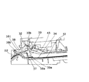
図1は、中間搬送ローラ32周辺の構成を説明する図であり、図1において、38は第1規制部材としての第1押さえ部材、39は第2規制部材としての第2押さえ部材である。
FIG. 1 is a diagram for explaining the configuration around the
第1押さえ部材38は、中間搬送ローラ32のニップ位置よりも上流側に本発明に係る支持手段を構成する揺動軸としての支点38bを有して回動(揺動、移動)可能に支持されており、バネなどの付勢手段によって矢印Aの方向に付勢されている。この付勢手段の付勢力は、搬送されてくるシートの押圧力よりも小さく、搬送されてくるシートが付勢力に抗して第1押さえ部材38を回動させ、かつシートにダメージを与えない範囲に設定される。付勢手段はバネなどを設けず、第1押さえ部材38がその自重によって規制位置へ向かって付勢されるようにしても良い。規制位置は第1押さえ部材38が不図示のストッパに突き当たって停止する位置である。
The first pressing
第1押さえ部材38は、シートの搬送中は第1当接部38cがシートに押されることによって図中、反時計回りに回動(揺動、移動)し、上方位置(退避位置)まで退避する。また、第1押さえ部材38は、シートが搬送されていない時は中間積載部34の積載面から所定の間隔離れた位置(規制位置)にあり、図1に示す概略断面図においては、下面38aは第1整合基準壁37と交差している。ここで、第1押さえ部材38において、第1当接部38cは支点38bよりも下流側に設けられている。
The first pressing
第2押さえ部材39は中間搬送ローラ32のニップ位置よりも下流側でシートの先端に当接するように、本発明に係る支持手段を構成する支点(揺動軸)39bを支点として回動可能に支持され、バネなどの付勢手段によって矢印Bの方向に付勢されている。この付勢手段もまた、その付勢力は第1押さえ部材38を付勢する付勢手段と同程度の付勢力である。不図示のストッパに付勢されて停止している位置が第2押さえ部材39の規制位置
である。
As the second pressing
第2押さえ部材39も、シートの搬送中は第2当接部39cがシートに押されることによって図中、反時計回りに回動し、規制位置から上方位置(退避位置)まで退避する。シートが搬送されていないとき、すなわち、第1押さえ部材38と第2押さえ部材39とが規制位置に位置する場合、第1押さえ部材38の下面38aは第2押さえ部材39の下面39aよりも下方に位置する。ここで、第1当接部38cは第2当接部39cよりも上流側に設けられている。このように、本発明に係る支持手段は、第1当接部38c,第2当接部39cがシートに押されることによって第1押さえ部材38,第2押さえ部材39が移動し、第1当接部38c,第2当接部39cにシートに当接している間、第1押さえ部材38,第2押さえ部材39をそれぞれ規制位置から退避位置に移動させるように構成している。
The second pressing
図4は中間積載部34を上方から見た図であり、40a,40b,40cはシートの搬送方向に直交する方向を整合するジョガー、41はシートの搬送方向と直交する方向の第2整合基準壁、42は整合されたシート束を綴じるステイプラである。排出ローラ33は、上側のローラ33aが下側のローラ33bに対して離間可能に支持されており、シートの整合中は上ローラ33aを離間しておくことによって整合が可能になり、ステイプル処理終了後は再度ニップしてシートを積載トレイ35に排出、積載する。
FIG. 4 is a view of the intermediate stacking
ジョガー40a,40b,40cのうち、ジョガー40a,40bは排出ローラ33a,33bよりも下流にあり、シートの上下面を支えることができるように略コの字型になっており、ステイプル処理後のシートを積載トレイ35に排出するためにジョガーの下面がシートの幅よりも外側になる位置まで退避可能である。また、排出ローラ33a,33bの上流にあるジョガー40cは、ジョガー40aによって押されて動くことによって、ジョガー40aとジョガー40cは同期してシートを整合することが可能である。整合ローラ36は中間積載部34のシート積載面に対して上下に移動することが可能であり、下降時は中間積載部34上のシートの表面に当接してシートを移動させ、上昇時はシートが中間積載部34に搬入されるのに支障のない位置まで退避する。
Among the
次に、シート処理部3におけるシート処理動作について説明する。
Next, a sheet processing operation in the
シートがシート処理部3に搬送されると、入口ローラ31で搬送されたシートは中間搬送ローラ32によって、中間積載部34に排出される。シートが中間積載部34に入ってくる前に、ジョガー40a,40b,40cはシートを押す整合面がシートの搬送領域よりも所定量広い位置に移動されるが、この位置へ移動してもシートの下面は略コの字型のジョガー40a,40bによって支持される。また、遅くともシートの後端が中間搬送ローラ32から抜ける前までに排出ローラ33aは図4に示す離間位置に移動し回転を停止する。これによって、中間搬送ローラ32を抜けたシートは中間積載部34に積載される。
When the sheet is conveyed to the
ここで、図5〜8を使用してシート搬入時の第1押さえ部材38と第2押さえ部材39の動作を説明する。
Here, the operation of the first pressing
図5〜8は、既に先行シートS1が中間積載部34に積載された状態で、後続シートS2が搬送され中間積載部34に積載されるまでの状態を説明するための図である。
5 to 8 are diagrams for explaining a state in which the succeeding sheet S2 is conveyed and stacked on the intermediate stacking
図5では、第1押さえ部材38と第2押さえ部材39とは、規制位置にある状態を示している。そして、後続シートS2は図5に示す矢印Cの方向に搬送され、シート先端は中間搬送ローラ32に達する前に第1押さえ部材38に当接し、図6に示すように後続シー
トS2が搬送されることによって第1押さえ部材38が矢印Dの方向に回動する。これにより、第1押さえ部材38は、退避位置に位置することとなる(図6参照)。このとき、既に中間積載部34に積載されている先行シートS1の後端の浮き上がりは、第2押さえ部材39によって中間搬送ローラ32のニップ線の下側に押さえられている。
In FIG. 5, the first pressing
後続シートS2の先端が中間搬送ローラ32にニップされ、さらに第2押さえ部材39に当接すると、図7に示すように第2押さえ部材39が矢印Eの方向に回動し、第2押さえ部材39も退避位置に移動する。第2押さえ部材39がシートによって上方へ回動し始めたとき、後続シートS2の先端と、先行シートS1の後端はシート搬送方向において略同じ位置にあるが、高さ方向で段差がある。このため、第2押さえ部材39が上方へ回動することによって先行シートS1の後端が浮き上がってきた時には、既に、後続シートS2の先端は先行シートS1の後端よりも下流に移動しており、後続シートS2の先端が先行シートS1の後端に衝突することはない。
When the leading edge of the succeeding sheet S2 is nipped by the intermediate conveying
後続シートS2の後端が中間搬送ローラ32のニップから抜けると同時に、第1押さえ部材38の第1当接部38cからも離れるので、図8のように第1押さえ部材38が矢印Fの方向に回動して所定の規制位置まで戻り、後続シートS2および先行シートS1の後端を中間積載部34に押さえつける。
Since the trailing edge of the succeeding sheet S2 comes out of the nip of the intermediate conveying
第1押さえ部材38は、支点38bが中間搬送ローラ32や第1当接部38cよりも上流に位置し、中間搬送ローラ32よりも上流でシート先端が当接するように配置されており、さらに、中間積載部34に積載されたシートの後端を中間積載部34のシート積載面に押さえつける方向に付勢されているため、シート後端のカールが大きくても確実に中間積載部34のシート積載面に押さえつけることが出来る。また、後続シートS2が中間搬送ローラ32を抜けると第2押さえ部材39も付勢力によって矢印Gの方向に回動して所定位置に戻るが(図8参照)、第1押さえ部材38がシート後端を押さえるため、第2押さえ部材39はシート後端の浮き上がりに邪魔されることなく確実に所定の規制位置まで戻ることができ、次のシートS3の搬入時に図5に示す状態に戻ることができる。
The first pressing
このようにして、シートが中間積載部34に積載されると、まずジョガーの移動によってシートの幅方向を整合するが、このとき基準側となるジョガー40bは、整合面が第2整合基準壁41と同一面となる位置に固定され、ジョガー40aとこれに連動して動作するジョガー40cがシートを第2整合基準壁41側に移動させることによってシートの幅方向が整合される。
Thus, when the sheets are stacked on the intermediate stacking
次に、整合ローラ36が下降してシートの表面に当接し、シートを第1整合基準壁37側に移動させることによって、シート搬送方向の整合を行う。
Next, the
ステイプルする所定の枚数に達するまで同様の動作を繰り返し、最終シートの整合が終了すると、ジョガー40a,40cをシート端面に突き当たる位置まで移動して整合を完了させた状態で、ステイプラ42を駆動してシートを綴じる。その後ジョガー40a,40bの下面がシートの幅よりも広い位置まで完全に退避するとともに、排紙ローラ33a,33bをニップしてシート束を搬送することによって、シート束を積載トレイ35に排出、積載する。
The same operation is repeated until the predetermined number of sheets to be stapled is reached. When the alignment of the final sheet is completed, the
なお、第1押さえ部材38の規制位置において中間積載部34の積載面に対する下面38aの位置は、ステイプラ42のステイプル可能厚さと略同一のクリアランスを保った位置に設定されている。これによって、先行シートS1の後端に後続シートS2の先端が衝突しない位置までシート後端を押さえるのと同時に、シートの整合中に第1押さえ部材38がシートの後端の浮きあがりを押さえることによって、シートの移動の抵抗となり、整
合不良が発生するのを防止している。
Note that the position of the
また、図9に示すように第1押さえ部材38および第2押さえ部材39はシート搬送方向に略直交する方向に複数設けられており、特に中間積載部34上で浮き上がる可能性の大きいシートの両端部を押さえることができるように設けられている。
Further, as shown in FIG. 9, a plurality of first
以上のように、本実施例によれば、シート処理装置内でシートに処理を行うために中間積載部に積載されたシートの後端の浮き上がりをより確実に規制することができ、シートのダメージやジャムの発生を防止することができる。 As described above, according to the present exemplary embodiment, it is possible to more reliably regulate the lifting of the trailing edge of the sheet stacked on the intermediate stacking unit in order to process the sheet in the sheet processing apparatus, and damage the sheet. And jam can be prevented.
なお、本実施例においては、シート処理装置内でシートに処理を行うために中間積載部に積載されたシートについて説明したが、これに限らず、積載部にシートを積載する場合であれば、本発明を好適に適用することができる。 In the present exemplary embodiment, the sheets stacked on the intermediate stacking unit in order to perform processing on the sheet in the sheet processing apparatus have been described. The present invention can be preferably applied.
[参考例]
図10,11は参考例について説明する図である。なお、実施例1と同様の構成部分については同一の符号を付して、その説明は省略する。
[Reference example]
10 and 11 are diagrams illustrating a reference example . In addition, the same code | symbol is attached | subjected about the component similar to Example 1, and the description is abbreviate | omitted.
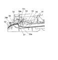
本参考例の構成においては、切り替え手段として第1押さえ部材38を駆動するソレノイド45を有するものであり、ソレノイド45により、第1押さえ部材38を図10に示す退避位置と、図11に示す規制位置とに切り替えることが可能となっている。
The configuration of this reference example includes a
後続シートS2が搬送されて来ると、シート検出手段としてのセンサが後続シートS2を検出することにより、切り替え手段は、図10のように第1押さえ部材38に当接する前にソレノイド45を駆動して第1押さえ部材38を退避位置に移動させる。このとき中間積載部34上の先行シートS1は第2押さえ部材39によって浮き上がりを押さえられている。
When the succeeding sheet S2 is conveyed, a sensor as the sheet detecting means detects the succeeding sheet S2, so that the switching means drives the
後続シートS2が中間搬送ローラ32を抜けた後、図11のようにソレノイド45を解除することにより、第1押さえ部材38を規制位置に位置させることにより後続シートS2の後端を押さえる。ソレノイド45の解除は、センサによりシートが中間搬送ローラ32を抜けたかどうかを検出させることにより行うとよいが、ソレノイド45の駆動から所定時間後のタイミングで解除させるようにしてもよい。
After the succeeding sheet S2 passes through the
したがって、後続シートS2が搬送されてくる時に、後続シートS2の先端が第1押さえ部材38に当接して第1押さえ部材38を回動させるのではなく、第1押さえ部材38の位置の切り替えをソレノイド45によって行うので、第1押さえ部材38を規制位置に付勢する付勢力を大きくしても、後続シートS2の先端にダメージを与えることがないため、実施例1の場合よりも大きな力で中間積載部34上のシート後端を押さえることができる。このため、より確実にシートの浮き上がりを押さえることができる。
Therefore, when the succeeding sheet S2 is conveyed, the position of the first pressing
なお、本参考例においては、ソレノイド45を駆動することにより第1押さえ部材38を退避位置に移動させたが、これに限らず、ソレノイド45を駆動することによって第1押さえ部材38を図11に示すような規制位置に移動させるようにしてもよい。
In this reference example , the first pressing
また、第2押さえ部材39をソレノイドにより移動させるものであってもよい。第1押さえ部材38と第2押さえ部材39のうちソレノイド45により移動されないものには実施例1と同様、シートの先端が当接する当接部が設けられ、シートの先端が当接部に当接することによって回動するようになっている。
Further, the second pressing
図12,図13は本発明の実施例2について説明する図である。なお、実施例1,参考例と同様の構成部分については同一の符号を付して、その説明は省略する。 12 and 13 are diagrams for explaining a second embodiment of the present invention. In addition, the same code | symbol is attached | subjected about the component similar to Example 1, and a reference example, and the description is abbreviate | omitted.
本実施例の構成においては、第1押さえ部材38の位置を検出する位置検出手段としてのセンサ46を有し、第1押さえ部材38の検出部47を検出することによって、第1押さえ部材38が所定の規制位置に戻っていないことを検出する。
In the configuration of this embodiment, the first pressing
第1押さえ部材38が規制位置にあるべき場合において、図12に示すように、シートSの後端が極端にカールしているなどの原因によって第1押さえ部材38が規制位置に戻っていないことがセンサ46により検出された場合、制御手段により第1押さえ部材38が中間積載部34上のシート後端を中間搬送ローラ32のニップ線よりも下方に規制できていないと判断される。ここで、第1押さえ部材38が規制位置にあるべき場合とは、実施例1では、シートが第1押さえ部材38の第1当接部38cに当接していない場合、すなわち、シート搬送経路のうちシートが第1当接部38cに当接する範囲にシートが存在していない場合であり、また、参考例では、ソレノイド45が解除されている場合である。
In the case where the first pressing
このような場合に、制御手段により搬送手段を制御することによって、後続シートの中間積載部34への搬送を中止することによって、ジャムなどの発生を防止することができる。
In such a case, it is possible to prevent the occurrence of a jam or the like by stopping the conveyance of the succeeding sheet to the intermediate stacking
また、図13に示すように、中間積載部34に積載されたシートSの束の厚さがステイプル可能な所定厚さ以上になったことによって、第1押さえ部材38が所定の規制位置まで戻らなかったことをセンサ46が検出した場合、制御手段がこのジョブに対するステイプル処理を中止することによって、ステイプラの能力を超えた厚さのシート束をステイプルしてしまうことによるステイプラの故障を防止することができる。
Further, as shown in FIG. 13, when the thickness of the bundle of sheets S stacked on the intermediate stacking
ここで、制御手段は、少なくとも、上記のようなシート処理に関する動作を停止させるものであればよく、例えばシート処理装置本体の動作を停止させるものであってもよい。 Here, the control means only needs to stop at least the operation related to the sheet processing as described above, and may be, for example, a device that stops the operation of the sheet processing apparatus main body.
1 画像形成部
2 画像読取部
3 シート処理部
32 中間搬送ローラ
34 中間積載部
38 第1押さえ部材
38b 支点
38c 第1当接部
39 第2押さえ部材
39c 第2当接部
S1 先行シート
S2 後続シート
First
Claims (9)
前記シート搬送経路に沿って搬送されるシートの搬送方向下流端が当接する第1当接部と、前記シート積載部に積載されたシートの搬送方向上流端部の浮き上がりを規制する第1押さえ面と、を有する第1規制部材と、
前記シート搬送経路に沿って搬送されるシートの搬送方向下流端が当接する第2当接部と、前記シート積載部に積載されたシートの搬送方向上流端部の浮き上がりを規制する第2押さえ面と、を有する第2規制部材と、
を備えたシート処理装置であって、
前記第1規制部材を、前記シート積載部に積載されたシートの搬送方向上流端部の浮き上がりを前記第1押さえ面によって規制する第1規制位置と、前記第1規制位置から退避した第1退避位置と、の間で移動可能に支持するとともに、前記第2規制部材を、前記シート積載部に積載されたシートの搬送方向上流端部の浮き上がりを前記第2押さえ面によって規制する第2規制位置と、前記第2規制位置から退避した第2退避位置と、の間で移動可能に支持する支持手段を備え、
前記シート搬送経路に沿って搬送されたシートの搬送方向下流端が、前記第1当接部と当接することによって前記第1規制部材を前記第1規制位置から前記第1退避位置に移動させた後、前記第2当接部と当接することによって前記第2規制部材を前記第2規制位置から前記第2退避位置に移動させる際に、前記シート積載部に積載され、前記第2押さえ面により浮き上がりを規制されているシートの搬送方向上流端と衝突することなく、前記シート積載部に積載されたシートの搬送方向上流端よりも搬送方向下流に移動するよう前記第1規制部材及び前記第2規制部材が配置されていることを特徴とするシート処理装置。 A sheet stacking unit for stacking sheets conveyed along the sheet conveying path;
A first contact portion downstream end in the conveyance direction of the sheet conveyed along the sheet conveying path comes into contact, the first pressing surface for regulating the floating of the conveyance direction upstream end of the sheets stacked on the sheet stacking portion A first regulating member having
A second contact portion downstream end in the conveyance direction of the sheet conveyed along the sheet conveying path comes into contact, a second pressing surface for regulating the floating of the conveyance direction upstream end of the sheets stacked on the sheet stacking portion A second restriction member having
A sheet processing apparatus comprising:
A first restriction position where the first restriction member restricts lifting of the upstream end portion in the conveyance direction of the sheets stacked on the sheet stacking portion by the first pressing surface, and a first retraction position where the first restriction member is retracted from the first restriction position. position and, together with the movably supported between said second regulating member, second regulating position for regulating the floating of the conveyance direction upstream end portion of sheets stacked on the sheet stacking portion by the second pressing surface And a supporting means for supporting the second retracted position retracted from the second restricting position so as to be movable,
Downstream end in the conveyance direction of the sheet conveyed along the front Symbol sheet transport path, is moved to the first retracted position to the first regulating member from the first regulation position by contacting with said first contact portion and then, when moving to the second retracted position of the second restricting member from the second regulation position by contacting with the second contact portion, it is stacked on the sheet stacking portion, the second pressing surface by without colliding with the conveyance direction upstream end of the sheet is regulated from floating, the sheet than the conveying direction upstream end of the sheets stacked on the stacking unit so as to move in the conveying direction downstream of the first regulating member and the second 2. A sheet processing apparatus in which a regulating member is disposed.
前記第1押さえ面は、前記基準壁の搬送方向上流から前記基準壁と交差して前記シート積載部に積載されたシートの搬送方向上流端部の浮き上がりを規制することを特徴とする請求項1に記載のシート処理装置。 A reference wall against which an upstream end in the conveyance direction of the sheets stacked on the sheet stacking unit abuts,
Said first pressing face, claim, characterized in that for regulating the floating of the conveyance direction upstream of the reference wall in the conveyance direction upstream end of the sheets stacked on the sheet stacking portion and intersecting the reference wall 1 The sheet processing apparatus according to 1.
動可能に支持する揺動軸を備え、
前記揺動軸は、前記第1当接部よりも搬送方向上流に設けられていることを特徴とする請求項1又は2に記載のシート処理装置。 The support means includes a swing shaft that the first restricting member supports in a swingable manner between the first restricting position and the first retracted position,
The sheet processing apparatus according to claim 1, wherein the swing shaft is provided upstream of the first contact portion in the transport direction.
前記第1規制部材が前記第1規制位置にあるべき場合において、前記位置検出手段により前記第1規制部材は前記第1規制位置に位置していないことが検出された場合、シート処理装置の動作を停止させる制御手段と、
を備えることを特徴とする請求項1ないし6のいずれか1項に記載のシート処理装置。 Position detecting means for detecting the position of the first regulating member;
In the case where the first regulating member should be on the first restricting position if, the first regulating member by said position detecting means is detected to be not located in the first restricting position, the operation of the sheet processing apparatus Control means for stopping
The sheet processing apparatus according to claim 1, further comprising:
前記第1規制位置にある前記第1規制部材により搬送方向上流端部を規制されたシートの束の厚さが、前記シート処理部により処理可能な厚さとなるように前記第1規制位置が設定されていることを特徴とする請求項1ないし7のいずれか1項に記載のシート処理装置。 A sheet processing unit for processing a bundle of sheets stacked on the sheet stacking unit;
The thickness of the stack of sheets is restricted conveyance direction upstream end portion by said first regulating member in a first restricting position, the sheet processing said first restricting position set so that can be processed thickness by unit The sheet processing apparatus according to claim 1, wherein the sheet processing apparatus is provided.
前記画像形成部により画像が形成されたシートを積載する請求項1ないし8のいずれか1項に記載のシート処理装置と、
を備えたことを特徴とする画像形成装置。 An image forming unit for forming an image on a sheet;
The sheet processing apparatus according to any one of claims 1 to 8, wherein sheets on which images are formed by the image forming unit are stacked.
An image forming apparatus comprising:
Priority Applications (4)
| Application Number | Priority Date | Filing Date | Title |
|---|---|---|---|
| JP2005128083A JP4708845B2 (en) | 2005-04-26 | 2005-04-26 | Sheet processing apparatus and image forming apparatus |
| US11/405,461 US7697883B2 (en) | 2005-04-26 | 2006-04-18 | Sheet processing apparatus and image forming apparatus |
| CN200610078107.3A CN100519378C (en) | 2005-04-26 | 2006-04-26 | Sheet processing apparatus and image forming apparatus |
| US12/712,328 US8170463B2 (en) | 2005-04-26 | 2010-02-25 | Sheet processing apparatus and image forming apparatus |
Applications Claiming Priority (1)
| Application Number | Priority Date | Filing Date | Title |
|---|---|---|---|
| JP2005128083A JP4708845B2 (en) | 2005-04-26 | 2005-04-26 | Sheet processing apparatus and image forming apparatus |
Publications (3)
| Publication Number | Publication Date |
|---|---|
| JP2006306522A JP2006306522A (en) | 2006-11-09 |
| JP2006306522A5 JP2006306522A5 (en) | 2009-11-05 |
| JP4708845B2 true JP4708845B2 (en) | 2011-06-22 |
Family
ID=37187055
Family Applications (1)
| Application Number | Title | Priority Date | Filing Date |
|---|---|---|---|
| JP2005128083A Active JP4708845B2 (en) | 2005-04-26 | 2005-04-26 | Sheet processing apparatus and image forming apparatus |
Country Status (3)
| Country | Link |
|---|---|
| US (2) | US7697883B2 (en) |
| JP (1) | JP4708845B2 (en) |
| CN (1) | CN100519378C (en) |
Families Citing this family (19)
| Publication number | Priority date | Publication date | Assignee | Title |
|---|---|---|---|---|
| JP4708845B2 (en) * | 2005-04-26 | 2011-06-22 | キヤノン株式会社 | Sheet processing apparatus and image forming apparatus |
| US7850161B2 (en) * | 2006-03-31 | 2010-12-14 | Canon Kabushiki Kaisha | Sheet processing apparatus and image forming apparatus |
| JP5063309B2 (en) | 2007-11-19 | 2012-10-31 | キヤノン株式会社 | Sheet stacking apparatus, sheet processing apparatus, image forming apparatus |
| JP5284047B2 (en) | 2007-12-07 | 2013-09-11 | キヤノン株式会社 | Sheet stacking apparatus, sheet processing apparatus, and image forming apparatus |
| JP5169642B2 (en) * | 2008-05-28 | 2013-03-27 | 株式会社リコー | Paper discharge device and image forming apparatus |
| JP5421032B2 (en) * | 2009-08-31 | 2014-02-19 | ニスカ株式会社 | Sheet stacking apparatus and image forming system having the same |
| JP5392486B2 (en) * | 2009-10-19 | 2014-01-22 | コニカミノルタ株式会社 | Image forming apparatus and control method thereof |
| JP5555013B2 (en) * | 2010-03-05 | 2014-07-23 | キヤノン株式会社 | Sheet processing apparatus and image forming apparatus |
| JP5360036B2 (en) | 2010-11-08 | 2013-12-04 | ブラザー工業株式会社 | Image forming apparatus |
| JP2012158427A (en) | 2011-01-31 | 2012-08-23 | Brother Industries Ltd | Sheet carrying device, image reader, and image forming device |
| JP5429239B2 (en) * | 2011-07-22 | 2014-02-26 | コニカミノルタ株式会社 | Sheet stacking device and post-processing device |
| JP5503708B2 (en) | 2011-10-06 | 2014-05-28 | キヤノン株式会社 | Sheet processing apparatus and image forming apparatus |
| JP6201375B2 (en) * | 2013-03-29 | 2017-09-27 | ブラザー工業株式会社 | Image forming apparatus |
| JP2015051833A (en) * | 2013-09-06 | 2015-03-19 | キヤノン株式会社 | Sheet housing device and image forming apparatus equipped with the same |
| JP7118807B2 (en) | 2018-08-22 | 2022-08-16 | キヤノン株式会社 | Stacking device and image forming device |
| US11215946B2 (en) | 2019-06-07 | 2022-01-04 | Canon Kabushiki Kaisha | Sheet processing apparatus and image forming system |
| US11518638B2 (en) * | 2019-11-26 | 2022-12-06 | Canon Kabushiki Kaisha | Sheet conveyance apparatus, sheet processing apparatus, and image forming system |
| US11565903B2 (en) | 2020-07-07 | 2023-01-31 | Canon Kabushiki Kaisha | Sheet alignment apparatus, sheet processing apparatus, and image forming system |
| JP7079299B2 (en) * | 2020-08-25 | 2022-06-01 | 日機装株式会社 | Laminating device with sheet straightening means |
Citations (4)
| Publication number | Priority date | Publication date | Assignee | Title |
|---|---|---|---|---|
| JPH0653558U (en) * | 1992-10-20 | 1994-07-22 | アンリツ株式会社 | Paper transport device |
| JP2001348155A (en) * | 2000-06-07 | 2001-12-18 | Nisca Corp | Sheet storage device |
| JP2004059314A (en) * | 2002-07-31 | 2004-02-26 | Canon Inc | Sheet post-processing device and image forming device having this |
| JP2004299855A (en) * | 2003-03-31 | 2004-10-28 | Canon Inc | Sheet delivering device, sheet processing device, and image forming apparatus |
Family Cites Families (29)
| Publication number | Priority date | Publication date | Assignee | Title |
|---|---|---|---|---|
| US4789150A (en) * | 1986-06-30 | 1988-12-06 | Xerox Corporation | Sheet stacking apparatus with trail edge control flaps |
| GB2215313B (en) * | 1988-01-20 | 1992-05-20 | Xerox Corp | Sheet delivery and stacking apparatus |
| JPH07144812A (en) * | 1993-11-20 | 1995-06-06 | Ricoh Co Ltd | Recording paper tray |
| JPH0840621A (en) * | 1994-08-02 | 1996-02-13 | Ricoh Co Ltd | Electron photographing device |
| EP0702276B1 (en) * | 1994-09-14 | 1999-11-17 | Konica Corporation | Sheet sorting apparatus |
| US6352253B1 (en) * | 1998-02-20 | 2002-03-05 | Canon Kabushiki Kaisha | Discharged sheet stacking apparatus and image forming apparatus having such stacking apparatus |
| JP3606360B2 (en) * | 1999-03-26 | 2005-01-05 | シャープ株式会社 | Sheet discharge mechanism |
| US6412774B1 (en) | 1999-06-11 | 2002-07-02 | Nisca Corporation | Sheet receiving apparatus |
| JP2001328758A (en) * | 1999-07-09 | 2001-11-27 | Ricoh Co Ltd | Sheet handling device and image forming device |
| JP3517619B2 (en) * | 1999-11-04 | 2004-04-12 | キヤノン株式会社 | Sheet post-processing apparatus and image forming apparatus |
| JP2001261225A (en) * | 2000-03-16 | 2001-09-26 | Ricoh Elemex Corp | Post-treating device of image forming apparatus |
| JP3877510B2 (en) * | 2000-09-11 | 2007-02-07 | シャープ株式会社 | Paper discharge device for image forming apparatus |
| JP2002211814A (en) * | 2001-01-12 | 2002-07-31 | Ricoh Co Ltd | Automatic document conveyance device |
| JP2002241028A (en) * | 2001-02-15 | 2002-08-28 | Ricoh Co Ltd | Paper delivery device |
| JP4579438B2 (en) * | 2001-03-29 | 2010-11-10 | キヤノン株式会社 | Sheet processing apparatus and image forming apparatus |
| US6942206B2 (en) * | 2001-08-31 | 2005-09-13 | Canon Kabushiki Kaisha | Sheet treating apparatus and image forming apparatus having the same |
| US6722646B2 (en) * | 2002-02-19 | 2004-04-20 | Canon Kabushiki Kaisha | Sheet treating apparatus and image forming apparatus |
| JP2003320502A (en) * | 2002-02-28 | 2003-11-11 | Canon Inc | Sheet post-treating apparatus and image forming apparatus |
| JP2003312925A (en) * | 2002-04-18 | 2003-11-06 | Kyocera Corp | Image forming device |
| JP4240909B2 (en) * | 2002-05-15 | 2009-03-18 | キヤノン株式会社 | Sheet post-processing apparatus and image forming apparatus provided with the apparatus |
| JP4047091B2 (en) * | 2002-07-31 | 2008-02-13 | キヤノン株式会社 | Sheet post-processing apparatus and image forming apparatus including the apparatus |
| JP4154278B2 (en) * | 2003-04-30 | 2008-09-24 | キヤノン株式会社 | Sheet processing apparatus and image forming apparatus |
| JP2004345858A (en) * | 2003-04-30 | 2004-12-09 | Canon Inc | Sheet treating device and image forming device |
| JP3733361B2 (en) * | 2003-07-15 | 2006-01-11 | キヤノン株式会社 | Sheet stacking apparatus and image forming apparatus |
| JP4281494B2 (en) * | 2003-09-26 | 2009-06-17 | 富士ゼロックス株式会社 | Paper discharge device and image forming apparatus |
| JP4401978B2 (en) * | 2004-02-20 | 2010-01-20 | キヤノン株式会社 | Sheet processing apparatus and image forming apparatus |
| JP2005001893A (en) * | 2004-09-30 | 2005-01-06 | Nisca Corp | Sheet storage device |
| JP4708845B2 (en) | 2005-04-26 | 2011-06-22 | キヤノン株式会社 | Sheet processing apparatus and image forming apparatus |
| US7850161B2 (en) | 2006-03-31 | 2010-12-14 | Canon Kabushiki Kaisha | Sheet processing apparatus and image forming apparatus |
-
2005
- 2005-04-26 JP JP2005128083A patent/JP4708845B2/en active Active
-
2006
- 2006-04-18 US US11/405,461 patent/US7697883B2/en not_active Expired - Fee Related
- 2006-04-26 CN CN200610078107.3A patent/CN100519378C/en active Active
-
2010
- 2010-02-25 US US12/712,328 patent/US8170463B2/en active Active
Patent Citations (4)
| Publication number | Priority date | Publication date | Assignee | Title |
|---|---|---|---|---|
| JPH0653558U (en) * | 1992-10-20 | 1994-07-22 | アンリツ株式会社 | Paper transport device |
| JP2001348155A (en) * | 2000-06-07 | 2001-12-18 | Nisca Corp | Sheet storage device |
| JP2004059314A (en) * | 2002-07-31 | 2004-02-26 | Canon Inc | Sheet post-processing device and image forming device having this |
| JP2004299855A (en) * | 2003-03-31 | 2004-10-28 | Canon Inc | Sheet delivering device, sheet processing device, and image forming apparatus |
Also Published As
| Publication number | Publication date |
|---|---|
| CN100519378C (en) | 2009-07-29 |
| US7697883B2 (en) | 2010-04-13 |
| US8170463B2 (en) | 2012-05-01 |
| US20100171256A1 (en) | 2010-07-08 |
| JP2006306522A (en) | 2006-11-09 |
| US20060239735A1 (en) | 2006-10-26 |
| CN1854047A (en) | 2006-11-01 |
Similar Documents
| Publication | Publication Date | Title |
|---|---|---|
| JP4708845B2 (en) | Sheet processing apparatus and image forming apparatus | |
| US10124969B2 (en) | Conveyance apparatus, image reading apparatus, and image forming apparatus | |
| US8038147B2 (en) | Sheet processing apparatus and image forming apparatus including the same | |
| US7887037B2 (en) | Sheet process apparatus | |
| US20070045924A1 (en) | Sheet stacking device and sheet processing device, and image forming apparatus provided therewith | |
| JP4827646B2 (en) | Sheet stacking apparatus, sheet processing apparatus, and image forming apparatus including the same | |
| JP4810277B2 (en) | Sheet processing apparatus and image forming apparatus | |
| JP2011088701A (en) | Paper processing device and image forming device | |
| JP5212270B2 (en) | Paper processing apparatus and image forming system | |
| JP4401978B2 (en) | Sheet processing apparatus and image forming apparatus | |
| JP2011126620A (en) | Sheet processing device | |
| JP2006193283A (en) | Sheet post-processing device | |
| JP4560437B2 (en) | Sheet stacking apparatus and image forming apparatus having the same | |
| JP2006306564A (en) | Sheet handling device, and image forming device | |
| JP4966062B2 (en) | Sheet processing apparatus and image forming apparatus | |
| JP4471720B2 (en) | Sheet processing apparatus and image forming apparatus | |
| JP4769618B2 (en) | Sheet processing apparatus and image forming apparatus | |
| JP2011126621A (en) | Sheet processing device | |
| JP4424794B2 (en) | Folded sheet stacking apparatus, sheet processing apparatus, and image forming apparatus | |
| JP2007145516A (en) | Sheet processing device and image forming device having the same | |
| JP2006021886A (en) | Sheet processing device, and image forming device having the same | |
| JP5665577B2 (en) | Sheet processing apparatus and image forming apparatus | |
| JP2008285239A (en) | Paper sheet conveying device and image forming system | |
| JP4012128B2 (en) | Sheet processing apparatus and image forming apparatus having the same | |
| US20060290045A1 (en) | Sheet alignment apparatus and sheet post-processing apparatus |
Legal Events
| Date | Code | Title | Description |
|---|---|---|---|
| A521 | Request for written amendment filed |
Free format text: JAPANESE INTERMEDIATE CODE: A523 Effective date: 20080425 |
|
| A621 | Written request for application examination |
Free format text: JAPANESE INTERMEDIATE CODE: A621 Effective date: 20080425 |
|
| A521 | Request for written amendment filed |
Free format text: JAPANESE INTERMEDIATE CODE: A523 Effective date: 20090916 |
|
| A977 | Report on retrieval |
Free format text: JAPANESE INTERMEDIATE CODE: A971007 Effective date: 20100409 |
|
| A131 | Notification of reasons for refusal |
Free format text: JAPANESE INTERMEDIATE CODE: A131 Effective date: 20100511 |
|
| A521 | Request for written amendment filed |
Free format text: JAPANESE INTERMEDIATE CODE: A523 Effective date: 20100712 |
|
| A131 | Notification of reasons for refusal |
Free format text: JAPANESE INTERMEDIATE CODE: A131 Effective date: 20100817 |
|
| A521 | Request for written amendment filed |
Free format text: JAPANESE INTERMEDIATE CODE: A523 Effective date: 20101015 |
|
| TRDD | Decision of grant or rejection written | ||
| A01 | Written decision to grant a patent or to grant a registration (utility model) |
Free format text: JAPANESE INTERMEDIATE CODE: A01 Effective date: 20110308 |
|
| A61 | First payment of annual fees (during grant procedure) |
Free format text: JAPANESE INTERMEDIATE CODE: A61 Effective date: 20110317 |
|
| R150 | Certificate of patent or registration of utility model |
Ref document number: 4708845 Country of ref document: JP Free format text: JAPANESE INTERMEDIATE CODE: R150 |