JP4769618B2 - Sheet processing apparatus and image forming apparatus - Google Patents
Sheet processing apparatus and image forming apparatus Download PDFInfo
- Publication number
- JP4769618B2 JP4769618B2 JP2006096438A JP2006096438A JP4769618B2 JP 4769618 B2 JP4769618 B2 JP 4769618B2 JP 2006096438 A JP2006096438 A JP 2006096438A JP 2006096438 A JP2006096438 A JP 2006096438A JP 4769618 B2 JP4769618 B2 JP 4769618B2
- Authority
- JP
- Japan
- Prior art keywords
- sheet
- unit
- conveyed
- pressing
- alignment
- Prior art date
- Legal status (The legal status is an assumption and is not a legal conclusion. Google has not performed a legal analysis and makes no representation as to the accuracy of the status listed.)
- Active
Links
Images


Description
本発明は、シート処理装置及びこれを備えた画像形成装置に関し、特にシートを整合して綴じ処理を行うものに関する。 The present invention relates to a sheet processing apparatus and an image forming apparatus including the sheet processing apparatus, and more particularly to an apparatus that performs sheet binding processing by aligning sheets.
従来、複写機等の画像形成装置においては、例えば画像形成された後のシートに対する綴じ処理等に要する手間を軽減するため、画像形成された後のシートを順次装置内に取り込み、このシートに対して綴じ処理等を施すシート処理装置を備えたものがある。 2. Description of the Related Art Conventionally, in an image forming apparatus such as a copying machine, for example, in order to reduce the labor required for binding processing for a sheet after image formation, the sheets after image formation are sequentially taken into the apparatus, Some of them include a sheet processing apparatus that performs binding processing and the like.
このようなシート処理装置では、シートに対して綴じ処理等を施す場合には、まずシートを中間ローラによって中間積載部へと搬送し、この後、中間積載部上でシートのシート搬送方向及びシート搬送方向と直交する方向(以下、幅方向という)の整合を行う。そして、この整合処理を繰り返し行い、最終ページの整合処理が終了した後、ステイプラ等の処理装置でステイプル処理等を行ってシート束にした後、排出手段により積載部に排出積載するようにしている。 In such a sheet processing apparatus, when binding processing or the like is performed on a sheet, the sheet is first transported to an intermediate stacking unit by an intermediate roller, and then the sheet transport direction of the sheet and the sheet on the intermediate stacking unit. Alignment in a direction orthogonal to the transport direction (hereinafter referred to as the width direction) is performed. Then, this alignment process is repeated, and after the final page alignment process is completed, a stapling process or the like is performed by a processing device such as a stapler to form a sheet bundle, and then discharged and stacked on the stacking unit by the discharge unit. .
ここで、このようなシート処理装置では、整合処理が施されたシートが、後続シートにより押し出されて整合が乱されないように、整合処理後のシートを押圧するシート押え手段を有している。 Here, such a sheet processing apparatus includes a sheet pressing unit that presses the aligned sheet so that the aligned sheet is not pushed out by the subsequent sheet and is not disturbed.
図14は、このようなシート押え手段の一例を示す図であり、図14において、400がシート押え手段である。そして、このシート押え手段400は、ソレノイド402の作用により軸401を支点として回動するレバー400bと、レバー400bの先端に設けられ、シートSと圧接するゴム等の弾性部材400aを備えている。
FIG. 14 is a diagram showing an example of such a sheet pressing unit. In FIG. 14,
なお、図14において、(a)はシート押え手段400の、軸401を支点としてレバー400bが回動してシートSを押える押え位置を、(b)はシート押え手段400の離間位置を示している。そして、(a)に示す押え位置にあるとき、シート押え手段400は弾性部材400aにより、シートSのシート搬送方向と直交するシート幅方向の一端部に近い1箇所を押圧するようにしている。
14A shows a pressing position of the
ところで、このような従来のシート処理装置及び画像形成装置において、シート押え手段400によりシートSを押圧した後、後続シートが中間積載部に搬送されると、この後続シートがシート押え手段400により押圧されているシートSに当接する。そして、このように後続シートが当接すると、シートSはシート押え手段400によりシート幅方向の一端部に近い1箇所のみが押圧されているため、シートSにはモーメントが働き、押圧箇所を中心に回転することがある。
In such a conventional sheet processing apparatus and image forming apparatus, after the sheet S is pressed by the
また、シート押え手段400のレバー400bは軸401を支点として回動するため、シートSを押える際、弾性部材400aの移動軌跡が円弧状となる。これにより、シート押え手段400(のレバー400b)の円弧状軌跡を確保するためのスペースが必要になり、装置全体が大型化する。
Further, since the
また、弾性部材400aの移動軌跡が円弧状となると、弾性部材400aの押圧するシートSの枚数、厚さに応じて弾性部材400aのシートとの当たり角度が変化する。ここで、このように当たり角度が変化すると、例えば弾性部材400aの一部だけがシートSに接触して他の部分が浮いた状態になり、弾性部材400aがシートSに面接触しない。
Further, when the movement locus of the
この結果、シート押え手段400の押え圧が減少し、安定してシートSを押えることができなくなる。また、弾性部材400aがシートSに斜めに当たって斜めに離間するため、シートSが移動し、整合が乱れることもある。
As a result, the presser pressure of the
なお、シート押え手段400の押え性能をアップさせるため弾性部材400aの当接圧を大きくするよう、例えばソレノイド402をパワーアップした場合、弾性部材400aがシートSに接触するときの速度が増加する。そして、このように弾性部材400aの速度が増加すると、これに伴い接触時に発生する音が非常に大きくなる。
For example, when the
そこで、本発明は、このような現状に鑑みてなされたものであり、整合されたシートを確実に押えることができ、かつシートを押えるときの音を低減することのできるシート処理装置及び画像形成装置を提供することを目的とするものである。 Accordingly, the present invention has been made in view of such a current situation, and can provide a sheet processing apparatus and an image forming apparatus that can reliably press the aligned sheets and can reduce noise when the sheets are pressed. The object is to provide an apparatus.
本発明は、処理されるシートが積載されるシート積載手段と、前記シート積載手段にシートを搬送するシート搬送手段とを備え、前記シート積載手段に搬送された後、整合されたシートの処理を行うシート処理装置において、前記シート積載手段に搬送されたシートを前記シート搬送手段のシート搬送方向と直交する幅方向に移動させて、搬送された位置から幅方向にずれた位置に整合する整合部と、前記整合部によるシートの整合を妨げない退避位置と、前記シート搬送手段により後続シートが前記シート積載手段に搬送される際、前記整合部により整合されたシートの、搬送される後続シートに対して幅方向でずれた部分を押える押圧位置と、に移動可能な押え手段と、を備え、前記押え手段には、前記押え手段が前記押圧位置へ移動した際、前記整合部により整合されたシートに圧接する圧接部がシート搬送方向に沿って複数設けられ、前記複数の圧接部は、中空部を有する弾性部材により構成され、前記整合部により整合されたシートに少なくとも一部が当接した後、シートに面接触の状態で弾性的に圧接することを特徴とするものである。 The present invention includes a sheet stacking unit on which sheets to be processed are stacked, and a sheet transport unit that transports the sheet to the sheet stacking unit, and processes the aligned sheets after being transported to the sheet stacking unit. In a sheet processing apparatus to perform, an alignment unit that moves a sheet conveyed to the sheet stacking unit in a width direction orthogonal to the sheet conveying direction of the sheet conveying unit and aligns the position shifted from the conveyed position in the width direction When a retracted position which does not interfere with the alignment of the sheet by the aligning unit, when the subsequent sheet by the sheet conveying means is conveyed to the sheet stacking means, the sheet is aligned by the alignment unit, a subsequent sheet to be conveyed and a pressing means being movable and the pressing position, the pressing the shift portion in the width direction against, the said pressing means, said pressing means is moved to the pressing position Here, the pressure-contacting portion for pressing the sheets aligned by the alignment unit is provided with a plurality along the sheet conveying direction, the plurality of press-contact portion is constituted by an elastic member having a hollow portion, which is aligned by the alignment unit After at least a part of the sheet comes into contact with the sheet, the sheet is elastically pressed against the sheet in a surface contact state .
本発明のように、押え手段に、押圧位置へ移動した際、整合されたシートに圧接する複数の圧接部を設け、この複数の圧接部を押え手段の押圧位置への移動に伴い、整合されたシートに少なくとも一部が当接した後、シートに弾性的に面接触するように構成する。これにより、整合されたシートを確実に押えることができ、後続シートが搬送されてもシートの整合状態を維持することができる。また、シートを押えるときの音を低減することができる。 As in the present invention, the presser means is provided with a plurality of press contact portions that press-contact the aligned sheets when moved to the press position, and the plurality of press contact parts are aligned with the movement of the press means to the press position. After at least a part of the sheet comes into contact with the sheet, the sheet is elastically brought into surface contact. Accordingly, the aligned sheets can be reliably pressed, and the aligned state of the sheets can be maintained even if the subsequent sheet is conveyed. Further, it is possible to reduce the sound when pressing the sheet.
以下、本発明を実施するための最良の形態について図面を用いて詳細に説明する。 The best mode for carrying out the present invention will be described below in detail with reference to the drawings.
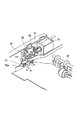
図1は、本発明の第1の実施の形態に係るシート処理装置を備えた画像形成装置の概略構成を示す図であり、図1において、100は画像形成装置、101は画像形成部1等を備えた画像形成装置本体である。この画像形成装置本体101の上部には、画像形成部1により画像が形成された後、選択的に搬送されたシートに対しステイプル等の処理を行うシート処理装置3が設けられ、さらにこのシート処理装置3の上方には画像読取装置2が取り付けられている。
FIG. 1 is a diagram showing a schematic configuration of an image forming apparatus provided with a sheet processing apparatus according to a first embodiment of the present invention. In FIG. 1, 100 is an image forming apparatus, 101 is an
なお、この画像形成装置100は、画像読取装置2とシート処理装置3との間に画像形成部1により画像形成されたシートを排出する排紙空間Pを設けた機内排紙型のものである。
The
ここで、原稿画像を読み取る画像読取装置2は、画像読取手段であるスキャナ部21と、ADF(自動原稿送り部)22とを有している。なお、このADF22は、スキャナ部21により原稿記載情報を光学的に読み取る際、原稿積載トレイ23上に積載される複数枚の原稿を給送ローラ24と、図示しない分離パッドとにより一枚ずつ分離搬送し、原稿読取位置25を通過させるものである。また、このADF22は装置後方の不図示のヒンジを中心に後方に開閉可能であり、原稿台ガラス26上に原稿を載置する場合に開閉されるようになっている。
Here, the
スキャナ部21は、原稿台ガラス上に載置された原稿の画像を不図示のガイド軸に沿って横方向に走査しながら読み取る光学キャリッジ27を備えており、この光学キャリッジ27により読み取った原稿情報を、CCD28で光電変換するようにしている。なお、ADF22による原稿読取の際は、光学キャリッジ27は所定位置に停止して搬送中の原稿を読み取るようになっている。
The
画像形成装置本体101は、電子写真方式によって画像(トナー像)を形成する画像形成部1の他、画像形成部1にシートを給送するシート給送部5、定着部12、第1及び第2シート排出部16A,19A等を備えている。
The image forming apparatus
ここで、画像形成部1は、感光体ドラム10及び不図示の帯電ローラ、現像器、トナー容器等を備えたプロセスカートリッジ9と、感光体ドラム10の表面を露光して感光体ドラム上に静電潜像を形成するレーザスキャナ11とを備えたものである。
Here, the
また、シート給送部5は、画像形成に供されるシートSが複数枚、積層状態で収納されている給紙カセット4と、給紙カセット4に収納されたシートSを給送するピックアップローラ6を有している。
Further, the
第1シート排出部16Aは、第1フラッパ13と、第1排紙ローラ16と、フェースアップ搬送路15とを有し、第2シート排出部19Aは、第2フラッパ18と、第2排紙ローラ19と、フェースダウン搬送路14を有している。
The first
なお、第2フラッパ18は、画像形成後のシートをシート処理装置3に向かわせる図1に示す位置と、画像形成後のシートを排紙空間Pに設けられた排紙積載部20に排出するシート排出位置とに切替え可能となっている。また、第1フラッパ13は、画像形成後のシートをフェースアップで排紙トレイ17に排出する図1に示す位置と、画像形成後のシートをフェースダウン搬送路14に向かわせる排出位置とに切替え可能となっている。
The
また、シート処理装置3は、第2フラッパ18の切り替えによって選択的に案内されたシートに対してステイプル等の処理を行うものである。そして、図2に示すように、シートの処理を行うための中間積載部34、中間積載部34にシートを搬送する中間搬送ローラ32、中間積載部34において処理が施されたシートを排出する接離可能な排紙ローラ対33を備えている。
Further, the
また、シート処理装置3は、中間積載部34に搬送されたシートの後端と当接してシートの搬送方向の端部を整合する第1整合基準壁37を備えている。さらに、中間積載部34に搬送されたシートを第1整合基準壁37側に搬送し、シートの後端を第1整合基準壁37に当接させる整合ローラ36を備えている。なお、この第1整合基準壁37と整合ローラ36とは第1整合部を構成する。
In addition, the
なお、31は第2フラッパ18の切り換えによりシート処理装置3に搬送されてくるシートを中間搬送ローラ32に搬送する入口ローラである。35はステイプル等の処理が施された後、排紙ローラ対33により排出されるシートを積載する排紙トレイ、43は中間積載部34の上方に設けられ、中間搬送ローラ32により搬送されたシートを中間積載部34に案内する搬送ガイドである。
次に、このように構成された画像形成装置100の画像形成時における動作について説明する。
Next, an operation at the time of image formation of the
シートに画像を形成する場合は、まずADF22の原稿積載トレイ23に原稿をセットし、この後、コピーボタンを押すと、ADF22の給紙ローラ24により原稿が原稿読取位置25に搬送される。そして、この原稿に対して不図示の光源から光を照射し、その反射光を光学キャリッジ27で読み取り、このようにして読み取った画像信号をCCD28で光電変換した後、画像形成部1のレーザスキャナ11に転送する。
In the case of forming an image on a sheet, first, a document is set on the
次に、レーザスキャナ11は、このように画像信号が入力されると、画像信号に応じたレーザ光を感光体ドラム10上に照射し、これにより感光体ドラム10上に静電潜像が形成される。この後、この静電潜像は不図示の現像器により現像されてトナー像として可視化され、このようにして感光体ドラム10上に形成されたトナー像は、感光体ドラム10の回転に伴って感光体ドラム10と転写ローラ10aとの間の転写ニップ部に搬送される。
Next, when the image signal is input in this way, the
一方、画像形成に供されるシートSは、給紙カセット4からピックアップローラ6及び分離ローラ対7によって1枚ずつ分離給紙され、この後、搬送ガイド8に沿って転写ニップ部に供給される。これにより感光体ドラム10上のトナー像は、転写ローラ10aにより、シートSに転写される。
On the other hand, the sheets S used for image formation are separated and fed one by one from the sheet feeding cassette 4 by the
そして、このように感光体ドラム10からトナー像が転写されたシートSは、定着部12に搬送され、この定着部12において加熱・加圧されて表面にトナー像が定着される。
Then, the sheet S on which the toner image is transferred from the
ここで、シートSに対する処理が不要で、かつシートをフェースアップで排紙する場合は、第1フラッパ13は図1に示すシート排出位置に設定される。これにより、トナー像定着後のシートSは、フェースアップ搬送路15に沿って搬送され、第1排紙ローラ16により排紙トレイ17にフェースアップの状態、即ちトナー像が形成された面を上方に向けた状態で排出される。
Here, when the processing on the sheet S is unnecessary and the sheet is discharged face up, the
一方、シートに対する処理が不要で、かつシートをフェースダウンで排紙する場合は、第1フラッパ13はシートSをフェースアップ搬送路14に向かわせる排出位置に設定される。また、第2フラッパ18は、シートを排紙空間Pに設けられた排紙積載部20に排出するシート排出位置に設定される。
On the other hand, when processing on the sheet is unnecessary and the sheet is discharged face down, the
これにより、トナー像定着後のシートSは、フェースダウン搬送路14に沿って搬送された後、第2排紙ローラ19により排紙積載部20にフェースダウンの状態、即ちトナー像が形成された面を下方に向けた状態で排出される。
As a result, after the toner image is fixed, the sheet S is conveyed along the face-down conveying
また、画像形成後のシートに対してステイプル等の処理を行うように設定されている場合、或は処理は施さないもののシート処理装置3から排出するように設定されている場合には、第2フラッパ18は、図1に示す位置に予め切り換えられる。
In addition, when it is set to perform a process such as stapling on the sheet after image formation, or when it is set to eject the sheet from the
そして、このような第2フラッパ18の切り換えにより、シートSは、入口ローラ31及びシート搬送手段である中間搬送ローラ32を経て中間積載部34まで搬送される。なお、図2において示す排紙ローラ対33は、上側のローラ33aが下側のローラ33bに対して離間可能に支持されている。そして、このようにシートSが中間積載部34まで搬送されるとき、排出ローラ対33は離間しているため、排出ローラ対33により、シートSが排出されることはない。
By such switching of the
この後、中間積載部34まで搬送されたシートは、後述するように1枚ずつ搬送方向及び幅方向の整合が行われ、整合されたシート束はステイプル(綴じ)処理が施される。そして、ステイプル処理終了後、離間していた排出ローラ対33が当接し、この排出ローラ対33により排紙トレイ35に排出される。
Thereafter, the sheets conveyed to the intermediate stacking
一方、シート処理装置3から排出するものの、ステイプル処理を行わない場合には、中間搬送ローラ32により搬送されたシートSは、中間積載部34に一時的に溜められることなく排出ローラ33により排紙トレイ35へと排出される。
On the other hand, when the sheet is discharged from the
ところで、処理されるシートを積載するシート積載手段である中間積載部34には、図3及び図4に示すように、シートの幅方向の位置を整合する第2整合基準壁41を備えている。また、シートを搬送方向と直交する方向(以下、幅方向という)に移動させ、第2整合基準壁41に当接させる第1〜第3ジョガー40a,40b、40cを備えている。また、整合されたシート束を綴じるステイプラ42を備えている。なお、この第2整合基準壁41と第1〜第3ジョガー40a,40b,40cとは第2整合部を構成する。
Meanwhile, as shown in FIGS. 3 and 4, the intermediate stacking
また、これら第1〜第3ジョガー40a,40b、40cは、シートS1の側端と当接するシート整合面40a1,40b1、40c1を備えている。ここで、本実施の形態において、第1及び第2ジョガー40a,40bは、シートを下方より支えることができるようコの字状となっている。また、ステイプル処理後のシートを積載トレイ35に排出することができるよう、シートを下方より支えている下面がシートの幅よりも外側になる位置まで退避可能となっている。
The first to
また、排紙ローラ対33の上流にある第3ジョガー40cは、不図示の連動機構により、第1ジョガー40aと連動して幅方向に移動するようになっており、これにより第1及び第3ジョガー40a,40cは同期してシートを整合することが可能となっている。さらに、第2整合基準壁41側に配された第2ジョガー40bは、シート整合面が第2整合基準壁41と同一面となる位置に固定されている。
The
整合ローラ36は中間積載部34に対して上下方向に移動可能であり、下降時は中間積載部34上のシートの表面に当接し、シートS1をシート搬送方向後端位置を整合する第1整合基準壁37に向かわせるようになっている。また、上昇時はシートが中間積載部34に搬入されるのに支障のない位置まで退避するようになっている。
The aligning
なお、本実施の形態においては整合部として直交する2方向の整合に対し、各方向専用の第1、第2整合部を設けた。しかし、例えば、綴じ手段であるステイプラの綴じ位置に向かってシートS1を斜めに移送する移送部材を設けた一つの整合部により2方向の整合を行うようにしてもよい。 In the present embodiment, the first and second matching portions dedicated to each direction are provided for matching in two directions orthogonal to each other as the matching portion. However, for example, the alignment in two directions may be performed by one alignment unit provided with a transfer member that obliquely transfers the sheet S1 toward the binding position of the stapler that is the binding means.
さらに、この中間積載部34は、図5に示すように、第1押え部材38、第2押え部材39を備えている。ここで、第1押え部材38は、中間搬送ローラ32のニップ位置よりも上流側に設けられた支点38bにより回動可能に保持されると共に、不図示のバネなどの付勢部材によって矢印Aの方向に付勢されている。
Further, the intermediate stacking
なお、この第1押え部材38は、シートが中間積載部34に搬送される際、搬送されるシートに押圧されて上方回動し、シートの搬送を妨げない位置まで退避する。また、シートが搬送されていない時は、中間積載部34の積載面34aから所定距離だけ上方の位置にあり、シートと当接する下面38aは第1整合基準壁37から突出している。
When the sheet is conveyed to the intermediate stacking
第2押え部材39は、支点39bにより回動可能に、かつ中間搬送ローラ32のニップ位置よりも下流側でシートの先端に当接する位置に保持され、不図示のバネなどの付勢部材によって矢印Bの方向に付勢されている。
The second pressing
なお、この第2押え部材39も、シートが中間積載部34に搬送される際、搬送されるシートに押圧されて上方回動し、シートの搬送を妨げない位置まで退避する。また、シートが搬送されていないとき、第1押え部材38の下面38aは第2押え部材の下面39aよりも下方に位置する。
When the sheet is conveyed to the intermediate stacking
また、図5において、70は中間搬送ローラ32の下流に設けられ、後述するように側端が整合された後のシートの側端部付近の上面を押圧して、後続シートによる先行シートの押し出しを防ぐための押圧ユニットである。
In FIG. 5, 70 is provided downstream of the
この押圧ユニット70は、図5及び図6に示すように、下方向に移動可能な押え手段であるベース部材71と、ベース部材71の下端に取り付けられ、圧接部を構成する圧接部材72と、リンク部材75とを備えている。
As shown in FIGS. 5 and 6, the
ここで、ベース部材71は上下方向に延びたレール90により上下方向の移動がガイドされるものである。また、圧接部材72は中空構造を有する略楕円状の弾性体により構成されるものであり、ベース部材71の下端に、複数、本実施の形態においては、2箇所取り付けられている。なお、この圧接部材72の下面72aは、シートを押圧する押圧面を構成している。圧接部材72を複数、搬送方向に所定の間隔で配置することにより、後続シートの搬送の際の摺接によってモーメントが発生しても先行シートの押圧状態が乱されることはない。本実施の形態において、圧接部材72は摺接によるモーメントに抗することができるよう、複数の圧接部材が所定の間隔で配置されているが、所定の長さの押圧面を連続的に構成した圧接部材を設けるようにしてもよい。
Here, the
リンク部材75はシート処理装置3の不図示のフレームに回動軸75aを支点として回動自在に軸支されたものであり、図6に示すバネ76により、図中矢印C方向に付勢されて図5の状態で停止している。
The
また、このリンク部材75は、ソレノイド73(のピン73a)とジョイント74を介して接続されており、ソレノイド73のONでジョイント74が引かれると、回動軸75aを中心に反時計方向に回動するようになっている。なお、図5は、ソレノイド73がOFFのときの状態を示している。
The
さらに、このリンク部材75は、カム穴75bを有しており、このカム穴75bにはベース部材71のボス71aが嵌合されている。そして、リンク部材75が図5に示す位置にある時、ベース部材71はリンク部材75との嵌合により上方に付勢され、図5の位置で停止している。
Further, the
次に、このように構成された押圧ユニット70を備えたシート処理装置3におけるシート処理動作について説明する。
Next, a sheet processing operation in the
シートがシート処理装置3に搬送されると、入口ローラ31で搬送されたシートは中間搬送ローラ32によって、中間積載部34に排出される。なお、シートが中間積載部34に搬送される前には、第1〜第3ジョガー40a〜40cは、シート整合面がシートの搬送領域よりも所定量広い位置に移動されている。これにより、シートは、第1〜第3ジョガー40a〜40cに突き当たることなく中間積載部34に搬送されると共に、シートの下面は第1〜第3ジョガー40a〜40cによって支持される。
When the sheet is conveyed to the
また、遅くともシートの後端が中間搬送ローラ32から抜ける前までに排紙ローラ対33は離間し、回転を停止する。これによって、中間搬送ローラ32を抜けたシートは中間積載部34に積載される。
Further, at the latest, before the trailing edge of the sheet comes off from the
なお、シートを中間積載部34に積載するとき、図3に示すようにベース部材71は、シートS1の幅よりも外側、即ちシート搬送範囲外に位置しているため、シートS1がベース部材71に衝突することもない。
When the sheets are stacked on the intermediate stacking
そして、このようにシートS1を中間積載部34に積載した後、まず第1ジョガー40a及び第1ジョガー40aと連動する第3ジョガー40cを図3に示す矢印R方向に移動させ、シートS1を幅方向に移動させる。
Then, after the sheet S1 is stacked on the intermediate stacking
このとき、既述したように第2ジョガー40bは、シート整合面が第2整合基準壁41と同一面となる位置に固定されている。そして、このように第1及び第3ジョガー40a,40cによってシートS1を移動させると、シートS1の側端が第2ジョガー40bのシート整合面及び第2整合基準壁41に当接し、これによりシートS1の幅方向の位置が整合される。なお、このときベース部材71は、圧接部材72が第1及び第3ジョガー40a,40cによるシートの整合を妨げない退避位置である上方位置に移動している。
At this time, as described above, the
次に、このようなシートS1の側端位置の整合が終了すると、整合ローラ36が下降してシートS1の表面に当接し、この後、シートS1を矢印Tに示す方向に移動させ、シートS1の後端を第1整合基準壁37に当接させる。これにより、シートS1の後端位置が規制され、シートS1の搬送方向の整合が行われる。
Next, when the alignment of the side edge positions of the sheet S1 is completed, the
そして、このようなシートS1の幅方向及び搬送方向の整合が終了した後、ソレノイド73が作動する。これにより、ベース部材71と一体に圧接部材72が、図6に示す矢印Qの方向へ移動し、後述する図10に示すように整合されたシートS1の側端部付近の上面を押圧する押圧位置に移動する。
Then, after such alignment of the sheet S1 in the width direction and the conveyance direction is completed, the
ここで、このようにベース部材71によって先行シートS1の側端部を押圧することにより、この後、中間積載部34に搬送される後続シートS2を、先行シートS1の後端の浮き上がりに邪魔されることなく確実に中間積載部34に搬送積載することができる。また、このとき先行シートS1はベース部材71に取り付けられている圧接部材72によって付勢されているため、後続シートS2との摩擦によりズレが生じることはない。
Here, by pressing the side end portion of the preceding sheet S1 by the
一方、このように中間積載部34に搬送された後続シートS2は、この後、第1〜第3ジョガー40a〜40cによって整合されるが、このときベース部材71はシートを受け入れるため図6の矢印Pの方向へ回避する。
On the other hand, the succeeding sheet S2 thus transported to the intermediate stacking
この結果、ベース部材71は、図5に示すように、中間積載部34の積載面34aの上方に移動し、後続シートS2がベース部材71(の圧接部材72)に衝突することはない。そして、このような動作をステイプルする所定の枚数に達するまで繰り返す。
As a result, as shown in FIG. 5, the
この後、最終シートの整合が終了すると、第1及び第3ジョガー40a,40cをシート端面に突き当てる位置まで移動して完全に整合させた状態で、綴じ手段であるステイプラ42を駆動してシートを綴じる。そして、最後に、図4に示す第1及び第2ジョガー40a,40bを、下面がシートの幅よりも広い位置まで完全に退避させると共に、排出ローラ対33を当接させてシート束を搬送することにより、シート束を積載トレイ35に排出、積載する。
Thereafter, when the alignment of the final sheet is completed, the first and
次に、押圧ユニット70によるシート押圧動作について説明する。
Next, the sheet pressing operation by the
例えば、中間積載部34にシートが搬送されるまでは、既述した図5に示すようにベース部材71は離間位置にあり、このとき圧接部材72のシートを押圧する押圧面を構成する下面72aと中間積載部34のシート積載面34aとの間には所定の隙間がある。
For example, until the sheet is conveyed to the intermediate stacking
そして、この状態からシートS1が搬送され、このシートS1が第1押え部材38及び第2押え部材39に衝突すると、図7に示すように第1押え部材38及び第2押え部材39はシートS1に押圧されて回動する。
When the sheet S1 is transported from this state and the sheet S1 collides with the first pressing
この後、さらにシートS1が搬送され、シートS1の後端が中間搬送ローラ32を通過すると、図8の(a)に示すようにシートS1の後端は、第1押え手段38と、第2押え手段39によって中間積載部側に払い落とされる。
Thereafter, when the sheet S1 is further conveyed and the rear end of the sheet S1 passes the
またさらに、シートS1が搬送されると、図8の(b)に示すように第1押え手段38と、第2押え手段39が完全に下降し、これら第1押え手段38及び第2押え手段39によりシートS1の後端の浮き上がりが規制される。そして、この後、整合シーケンスで説明したように、第1〜第3ジョガー40a〜40cと整合ローラ36による整合がシートに施される。
Further, when the sheet S1 is conveyed, as shown in FIG. 8B, the first presser means 38 and the second presser means 39 are completely lowered, and the first presser means 38 and the second presser means 39 restricts the lifting of the trailing edge of the sheet S1. Thereafter, as described in the alignment sequence, alignment by the first to
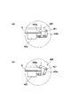
次に、このようにジョガー40a〜40c及び整合ローラ36による整合が終了すると、まずソレノイド73がONになり、これにより図9に示すようにピン73a、ジョイント74を介してリンク部材75が反時計方向に回動する。これに伴い、ボス71aとカム穴75bを介してリンク部材75に接続されているベース部材71が下降を開始し、やがて圧接部材72の下面72aの一部(先端部分)がシートS1に接触する。
Next, when the alignment by the
そして、圧接部材72は、既述したように圧接部材72は中空構造を有する略楕円状の弾性体により構成されたものであることから、この後、ベース部材71がさらに下降すると、圧接部材72は、徐々に潰れながらシートS1に圧接してゆく。
As described above, the
ここで、このようにシートS1に一部が接触した後、圧接部材72が徐々に潰れながらシートS1に圧接することにより、圧接部材72がシートS1に接触する時の音が小さくなる。つまり、本実施の形態のように、圧接部材72を中空構造を有する略楕円状の弾性体によって構成し、一部が接触した後、徐々に潰れながらシートS1に圧接するようにすることにより、圧接部材72がシートS1に接触する際の音の大きさを低減することができる。
Here, after a part of the sheet S1 comes into contact with the sheet S1 in this way, the
次に、ベース部材71の下降が終了すると、図10に示すように圧接部材72は弾性的に変形した状態でシートS1に圧接する。ここで、このように圧接部材72が変形しながらシートS1に弾性的に圧接することにより、例えばベース部材71が多少傾いていたり、シートS1に凹凸がある場合でも、シートS1との当たりムラを吸収することができる。
Next, when the descent of the
つまり、圧接部材72が弾性的にシートS1に圧接することにより、圧接部材72はシートS1に面接触することができ、これによりシートS1を同じ大きさの圧力で押えることができる。
That is, when the
また、既述したようにベース部材71の下面には圧接部材72が2箇所設けられており、このように圧接部材72を2箇所有することにより、図11において示す、T1及びT2の2箇所で、シートを押圧することができる。このため、この後、後続シートS2が搬送され、この後続シートS2により矢印T3で示す回転方向の押し出し力が加わっても、シートS1を回転させることなく安定して押えることができる。
Further, as described above, the
このように、ベース部材71の押圧位置への移動に伴って圧接部材72を整合されたシートS1に一部が当接した後、シートS1に弾性的に面接触するように構成することにより、整合されたシートS1を確実に押えることができる。また、シートS1を押えるときの音を低減することができる。
In this way, by configuring the
また、本実施の形態のように、シート押えユニット70を上下方向に垂直移動させるように構成することにより、シート押え手段を円弧状の移動軌跡で移動させる従来例と比較して設置スペースを狭くすることができ、装置全体の小型化が可能となる。
Further, as in the present embodiment, the
次に、本発明の第2の実施の形態について説明する。 Next, a second embodiment of the present invention will be described.
図12は本実施の形態に係るシート処理装置の構成を示す図である。なお、図12において、既述した図5と同一符号は、同一又は相当部分を示している。 FIG. 12 is a diagram showing a configuration of the sheet processing apparatus according to the present embodiment. In FIG. 12, the same reference numerals as those in FIG. 5 described above indicate the same or corresponding parts.
図12において、201は圧接部材であり、この圧接部材201はバネ等の弾性部材である弾性継ぎ手部材200を介してベース部材71に取り付けられている。そして、このようにベース部材71に弾性継ぎ手部材200を介して圧接部材201を取り付けることにより、シートS1に合わせて圧接部材201が移動することができる。
In FIG. 12, 201 is a pressure contact member, and this
これにより、例えばベース部材71が多少傾いていたり、整合されたシートS1に凹凸がある場合でも、圧接部材201は片当たりすることなく、安定した力でシートS1を押さえることができる。
Thereby, for example, even when the
また、本実施の形態においても、シートS1を2箇所において押えるようにしているので、シートS1を回転させることなく安定して押えることができる。さらに、このようなサスペンション構造とすることで、接触時において発生する音の大きさを低減することができる。 Also in the present embodiment, since the sheet S1 is pressed at two locations, the sheet S1 can be stably pressed without rotating. Furthermore, by using such a suspension structure, it is possible to reduce the volume of sound generated at the time of contact.
次に、本発明の第3の実施の形態について説明する。 Next, a third embodiment of the present invention will be described.
図13は本実施の形態に係るシート処理装置の構成を示す図である。なお、図13において、既述した図5と同一符号は、同一又は相当部分を示している。 FIG. 13 is a diagram showing the configuration of the sheet processing apparatus according to the present embodiment. In FIG. 13, the same reference numerals as those in FIG. 5 described above indicate the same or corresponding parts.
図13において、302は圧接部材、301は圧接部材302を保持している保持部材である下部ベース部材であり、下部ベース部材301はバネ等の弾性部材である弾性継ぎ手部材300を介してベース部材71に取り付けられている。つまり、本実施の形態において、圧接部材302は、下部ベース部材71、弾性継ぎ手部材300を介してベース部材71に取り付けられている。
In FIG. 13, 302 is a pressure contact member, 301 is a lower base member which is a holding member holding the pressure contact member 302, and the
そして、このようにベース部材71に下部ベース部材71及び弾性継ぎ手部材300を介して圧接部材302を取り付けることにより、シートS1に合わせて圧接部材302が移動することができる。これにより、ベース部材71が多少傾いていたり、シートS1に凹凸がある場合でも、圧接部材201は片当たりすることなく、安定した力でシートS1を押さえることができる。
Then, by attaching the pressure contact member 302 to the
また、本実施の形態においても、シートS1を2箇所において押えるようにしているので、シートS1を回転させることなく安定して押えることができる。さらに、このようなサスペンション構造とすることで、接触時において発生する音の大きさを低減することができる。 Also in the present embodiment, since the sheet S1 is pressed at two locations, the sheet S1 can be stably pressed without rotating. Furthermore, by using such a suspension structure, it is possible to reduce the volume of sound generated at the time of contact.
1 画像形成部
3 シート処理装置
32 中間搬送ローラ
34 中間積載部
36 整合ローラ
37 第1整合基準壁
38 第1押え部材
39 第2押え部材
40 ジョガー
41 第2整合基準壁
70 押圧ユニット
71 ベース部材
72 圧接部材
100 画像形成装置
200 弾性継ぎ手部材
201 圧接部材
300 弾性継ぎ手部材
301 下部ベース部材
302 圧接部材
S シート
DESCRIPTION OF
Claims (6)
前記シート積載手段に搬送されたシートを前記シート搬送手段のシート搬送方向と直交する幅方向に移動させて、搬送された位置から幅方向にずれた位置に整合する整合部と、
前記整合部によるシートの整合を妨げない退避位置と、前記シート搬送手段により後続シートが前記シート積載手段に搬送される際、前記整合部により整合されたシートの、搬送される後続シートに対して幅方向でずれた部分を押える押圧位置と、に移動可能な押え手段と、を備え、
前記押え手段には、前記押え手段が前記押圧位置へ移動した際、前記整合部により整合されたシートに圧接する圧接部がシート搬送方向に沿って複数設けられ、前記複数の圧接部は、中空部を有する弾性部材により構成され、前記整合部により整合されたシートに少なくとも一部が当接した後、シートに面接触の状態で弾性的に圧接することを特徴とするシート処理装置。 A sheet processing apparatus comprising: a sheet stacking unit on which sheets to be processed are stacked; and a sheet transport unit configured to transport a sheet to the sheet stacking unit, and processing the aligned sheets after being transported to the sheet stacking unit In
An alignment unit that moves the sheet conveyed to the sheet stacking unit in a width direction orthogonal to the sheet conveying direction of the sheet conveying unit and aligns the position shifted from the conveyed position in the width direction ;
A retracted position which does not interfere with the alignment of the sheet by the aligning unit, the time of the subsequent sheet by the sheet conveying means is conveyed to the sheet stacking means, the sheet is aligned by the alignment unit, for subsequent sheet conveyed comprising a pressing position for pressing the shift portion in the width direction, and pressing means movable in a,
The presser means is provided with a plurality of press contact portions along the sheet conveying direction that press-contact the sheets aligned by the aligning portion when the press means moves to the pressing position, and the plurality of press contact portions are hollow. A sheet processing apparatus comprising: an elastic member having a portion, wherein at least a part of the sheet is in contact with the sheet aligned by the aligning portion and then elastically pressed against the sheet in a surface contact state .
前記シート積載手段に搬送されたシートを前記シート搬送手段のシート搬送方向と直交する幅方向に移動させて、搬送された位置から幅方向にずれた位置に整合する整合部と、
前記整合部によるシートの整合を妨げない退避位置と、前記シート搬送手段により後続シートが前記シート積載手段に搬送される際、前記整合部により整合されたシートの、搬送される後続シートに対して幅方向でずれた部分を押える押圧位置と、に移動可能な押え手段と、を備え、
前記押え手段には、前記押え手段が前記押圧位置へ移動した際、前記整合部により整合されたシートに圧接する圧接部がシート搬送方向に沿って複数設けられ、前記複数の圧接部は、前記押え手段に弾性部材を介して取り付けられていることを特徴とするシート処理装置。 A sheet processing apparatus comprising: a sheet stacking unit on which sheets to be processed are stacked; and a sheet transport unit configured to transport a sheet to the sheet stacking unit, and processing the aligned sheets after being transported to the sheet stacking unit In
An alignment unit that moves the sheet conveyed to the sheet stacking unit in a width direction orthogonal to the sheet conveying direction of the sheet conveying unit and aligns the position shifted from the conveyed position in the width direction;
A retracted position that does not interfere with the alignment of the sheet by the aligning unit, and a subsequent sheet conveyed by the aligning unit when the subsequent sheet is conveyed to the sheet stacking unit by the sheet conveying unit A pressing position for pressing a portion displaced in the width direction, and a pressing means movable to
The pressing means is provided with a plurality of pressure contact portions along the sheet conveying direction that press-contact the sheets aligned by the alignment portion when the pressing means moves to the pressing position, and the plurality of pressure contact portions are features and to Resid over preparative processing apparatus that is attached through an elastic member to the pressing means.
前記シート積載手段に搬送されたシートを前記シート搬送手段のシート搬送方向と直交する幅方向に移動させて、搬送された位置から幅方向にずれた位置に整合する整合部と、
前記整合部によるシートの整合を妨げない退避位置と、前記シート搬送手段により後続シートが前記シート積載手段に搬送される際、前記整合部により整合されたシートの、搬送される後続シートに対して幅方向でずれた部分を押える押圧位置と、に移動可能な押え手段と、を備え、
前記押え手段には、前記押え手段が前記押圧位置へ移動した際、前記整合部により整合されたシートに圧接する圧接部がシート搬送方向に沿って複数設けられ、前記複数の圧接部は、保持部材により保持され、かつ前記保持部材は前記押え手段に弾性部材を介して取り付けられていることを特徴とするシート処理装置。 A sheet processing apparatus comprising: a sheet stacking unit on which sheets to be processed are stacked; and a sheet transport unit configured to transport a sheet to the sheet stacking unit, and processing the aligned sheets after being transported to the sheet stacking unit In
An alignment unit that moves the sheet conveyed to the sheet stacking unit in a width direction orthogonal to the sheet conveying direction of the sheet conveying unit and aligns the position shifted from the conveyed position in the width direction;
A retracted position that does not interfere with the alignment of the sheet by the aligning unit, and a subsequent sheet conveyed by the aligning unit when the subsequent sheet is conveyed to the sheet stacking unit by the sheet conveying unit A pressing position for pressing a portion displaced in the width direction, and a pressing means movable to
The presser means is provided with a plurality of press contact portions along the sheet conveying direction that press-contact the sheets aligned by the aligning portion when the press means moves to the press position, and the plurality of press contact portions are held held by members, and the holding member that is attached via an elastic member, wherein the to Resid over preparative processing apparatus to said pressing means.
前記シート積載手段に搬送されたシートのシート搬送方向と直交する方向の端部を整合する第2整合部と、を備えたことを特徴とする請求項1乃至4のいずれか1項に記載のシート処理装置。 The alignment unit includes a first alignment unit that aligns a sheet conveyance direction end of the sheet conveyed to the sheet stacking unit;
According to any one of claims 1 to 4, characterized in that and a second matching unit for matching the ends of the direction perpendicular to the sheet conveying direction of the conveyed sheet to said sheet stacking means Sheet processing device.
Priority Applications (3)
| Application Number | Priority Date | Filing Date | Title |
|---|---|---|---|
| JP2006096438A JP4769618B2 (en) | 2006-03-31 | 2006-03-31 | Sheet processing apparatus and image forming apparatus |
| US11/693,058 US7850161B2 (en) | 2006-03-31 | 2007-03-29 | Sheet processing apparatus and image forming apparatus |
| CN2007100914667A CN101045506B (en) | 2006-03-31 | 2007-03-30 | Sheet processing apparatus and image forming apparatus |
Applications Claiming Priority (1)
| Application Number | Priority Date | Filing Date | Title |
|---|---|---|---|
| JP2006096438A JP4769618B2 (en) | 2006-03-31 | 2006-03-31 | Sheet processing apparatus and image forming apparatus |
Publications (3)
| Publication Number | Publication Date |
|---|---|
| JP2007269437A JP2007269437A (en) | 2007-10-18 |
| JP2007269437A5 JP2007269437A5 (en) | 2009-05-14 |
| JP4769618B2 true JP4769618B2 (en) | 2011-09-07 |
Family
ID=38672627
Family Applications (1)
| Application Number | Title | Priority Date | Filing Date |
|---|---|---|---|
| JP2006096438A Active JP4769618B2 (en) | 2006-03-31 | 2006-03-31 | Sheet processing apparatus and image forming apparatus |
Country Status (1)
| Country | Link |
|---|---|
| JP (1) | JP4769618B2 (en) |
Families Citing this family (1)
| Publication number | Priority date | Publication date | Assignee | Title |
|---|---|---|---|---|
| JP6123309B2 (en) * | 2013-01-24 | 2017-05-10 | 株式会社リコー | Paper post-processing apparatus and image forming system |
Family Cites Families (2)
| Publication number | Priority date | Publication date | Assignee | Title |
|---|---|---|---|---|
| JPH0188673U (en) * | 1987-12-04 | 1989-06-12 | ||
| JPH05238621A (en) * | 1992-02-27 | 1993-09-17 | Sharp Corp | Sheet discharging device |
-
2006
- 2006-03-31 JP JP2006096438A patent/JP4769618B2/en active Active
Also Published As
| Publication number | Publication date |
|---|---|
| JP2007269437A (en) | 2007-10-18 |
Similar Documents
| Publication | Publication Date | Title |
|---|---|---|
| JP4429219B2 (en) | Sheet processing apparatus and image forming apparatus provided with the apparatus | |
| JP4708845B2 (en) | Sheet processing apparatus and image forming apparatus | |
| JP5078395B2 (en) | Sheet conveying apparatus, sheet processing apparatus, and image forming apparatus | |
| JP4810277B2 (en) | Sheet processing apparatus and image forming apparatus | |
| US7850155B2 (en) | Sheet folding apparatus, sheet post-processing apparatus and image forming apparatus | |
| JP4921290B2 (en) | Sheet processing apparatus and image forming apparatus | |
| WO2015141265A1 (en) | Sheet processing device and image forming device | |
| JP4871551B2 (en) | Sheet processing apparatus, image forming apparatus, and image forming system | |
| JP4920883B2 (en) | Sheet processing apparatus and image forming apparatus | |
| JP7200692B2 (en) | Sheet post-processing device and image forming system | |
| JP4769618B2 (en) | Sheet processing apparatus and image forming apparatus | |
| JP7404698B2 (en) | Sheet post-processing device and image forming system equipped with the same | |
| JP2002037512A (en) | Sheet after-treatment device and image forming device furnished with this device | |
| JP6361596B2 (en) | Sheet post-processing apparatus and image forming system including the same | |
| JP2006027865A (en) | Sheet handling device and image forming device having the same | |
| JP2017081665A (en) | Post-processing device and image formation apparatus | |
| JP2006193283A (en) | Sheet post-processing device | |
| JP2003020154A (en) | Paper post-processing device and image forming apparatus | |
| JP2006027864A (en) | Sheet processing device and image forming device having the same | |
| JP4966062B2 (en) | Sheet processing apparatus and image forming apparatus | |
| JP3332710B2 (en) | Sheet stacking apparatus and image forming apparatus | |
| JP2009161273A (en) | Sheet handling device and image forming device | |
| JP6299688B2 (en) | Sheet post-processing apparatus and image forming system including the same | |
| JP3437546B2 (en) | Feeding / conveying unit and image forming apparatus having the same | |
| JP4012128B2 (en) | Sheet processing apparatus and image forming apparatus having the same |
Legal Events
| Date | Code | Title | Description |
|---|---|---|---|
| A521 | Written amendment |
Free format text: JAPANESE INTERMEDIATE CODE: A523 Effective date: 20090325 |
|
| A621 | Written request for application examination |
Free format text: JAPANESE INTERMEDIATE CODE: A621 Effective date: 20090325 |
|
| A977 | Report on retrieval |
Free format text: JAPANESE INTERMEDIATE CODE: A971007 Effective date: 20110124 |
|
| A131 | Notification of reasons for refusal |
Free format text: JAPANESE INTERMEDIATE CODE: A131 Effective date: 20110208 |
|
| A521 | Written amendment |
Free format text: JAPANESE INTERMEDIATE CODE: A523 Effective date: 20110406 |
|
| TRDD | Decision of grant or rejection written | ||
| A01 | Written decision to grant a patent or to grant a registration (utility model) |
Free format text: JAPANESE INTERMEDIATE CODE: A01 Effective date: 20110614 |
|
| A01 | Written decision to grant a patent or to grant a registration (utility model) |
Free format text: JAPANESE INTERMEDIATE CODE: A01 |
|
| A61 | First payment of annual fees (during grant procedure) |
Free format text: JAPANESE INTERMEDIATE CODE: A61 Effective date: 20110620 |
|
| R150 | Certificate of patent or registration of utility model |
Ref document number: 4769618 Country of ref document: JP Free format text: JAPANESE INTERMEDIATE CODE: R150 Free format text: JAPANESE INTERMEDIATE CODE: R150 |
|
| FPAY | Renewal fee payment (event date is renewal date of database) |
Free format text: PAYMENT UNTIL: 20140624 Year of fee payment: 3 |