CN1270227C - Touch screen with rotationally isolated force sensor - Google Patents
Touch screen with rotationally isolated force sensor Download PDFInfo
- Publication number
- CN1270227C CN1270227C CNB028081463A CN02808146A CN1270227C CN 1270227 C CN1270227 C CN 1270227C CN B028081463 A CNB028081463 A CN B028081463A CN 02808146 A CN02808146 A CN 02808146A CN 1270227 C CN1270227 C CN 1270227C
- Authority
- CN
- China
- Prior art keywords
- touch
- sensor
- power
- overlayer
- force
- Prior art date
- Legal status (The legal status is an assumption and is not a legal conclusion. Google has not performed a legal analysis and makes no representation as to the accuracy of the status listed.)
- Expired - Fee Related
Links
Images


Classifications
-
- G—PHYSICS
- G06—COMPUTING; CALCULATING OR COUNTING
- G06F—ELECTRIC DIGITAL DATA PROCESSING
- G06F3/00—Input arrangements for transferring data to be processed into a form capable of being handled by the computer; Output arrangements for transferring data from processing unit to output unit, e.g. interface arrangements
- G06F3/01—Input arrangements or combined input and output arrangements for interaction between user and computer
- G06F3/03—Arrangements for converting the position or the displacement of a member into a coded form
- G06F3/041—Digitisers, e.g. for touch screens or touch pads, characterised by the transducing means
- G06F3/0414—Digitisers, e.g. for touch screens or touch pads, characterised by the transducing means using force sensing means to determine a position
- G06F3/04142—Digitisers, e.g. for touch screens or touch pads, characterised by the transducing means using force sensing means to determine a position the force sensing means being located peripherally, e.g. disposed at the corners or at the side of a touch sensing plate
-
- G—PHYSICS
- G06—COMPUTING; CALCULATING OR COUNTING
- G06F—ELECTRIC DIGITAL DATA PROCESSING
- G06F3/00—Input arrangements for transferring data to be processed into a form capable of being handled by the computer; Output arrangements for transferring data from processing unit to output unit, e.g. interface arrangements
- G06F3/01—Input arrangements or combined input and output arrangements for interaction between user and computer
- G06F3/03—Arrangements for converting the position or the displacement of a member into a coded form
- G06F3/041—Digitisers, e.g. for touch screens or touch pads, characterised by the transducing means
-
- G—PHYSICS
- G06—COMPUTING; CALCULATING OR COUNTING
- G06K—GRAPHICAL DATA READING; PRESENTATION OF DATA; RECORD CARRIERS; HANDLING RECORD CARRIERS
- G06K11/00—Methods or arrangements for graph-reading or for converting the pattern of mechanical parameters, e.g. force or presence, into electrical signal
- G06K11/06—Devices for converting the position of a manually-operated writing or tracing member into an electrical signal
Abstract
A touch screen uses one or more force sensors to determine location of the touch on the screen. Bending or twisting of the touch screen overlay, or of the support structure upon which the touch screen is mounted, may result in the detection of undesirable forces by force sensors. These undesirable forces may distort the measurement of the location of the touch on the screen. The force sensor is arranged to reduce the effects of flexure on the determination of the location of the touch. For example, a rotational softener, such as a rotational bearing or a pliable material may be included with the force sensor.
Description
Invention field
The present invention is generally at touch-screen, especially at the touch-screen that comes the senses touch position according to the touch force measurement that is applied to screen.
Background
Touch-screen provides a kind of interface simply and intuitively for computing machine or other data processing equipment.Keyboard for the data input is different with using, by an icon on the touch-screen or by writing or draw on screen, the user can come transmission information by touch-screen.In using, multiple information processing uses touch-screen.For the application such as cell phone, electronic organizers (PDA) and hand-held or laptop computer, the transparent touch-sensitive panel that uses on the information display such as LCD (LCD) or cathode ray tube (CRT) is useful especially.
Made in all sorts of ways to determine touch location, comprised electric capacity, resistance, acoustics and infrared technology.Be coupled in the touch force of the force transducer of touch-surface by detection, also can determine touch location.The touch-screen of operating by senses touch power has the several advantages that are better than above-mentioned other technology.Based on electric method, such as resistance and method electric capacity, need complicated touch-surface overlayer, described overlayer uses special material and a plurality of layer to guarantee the good electrical specification of shielding, and also keeps the good optical transmission by screen simultaneously.On the other hand, can form overlayer with simple single piece of material based on the touch-screen of power.In addition, as capacitive touch screen was desired, force transducer did not rely on the lossy of ground connection and is electrically connected, and can operate by hand, nail or other nonconducting touch tool touch of finger, band gloves.Different with surface acoustic wave techniques, force transducer relatively is not accumulated in the influence of dirt, dust or liquid on the touch-surface.At last, force transducer is less as the possibility that actual touch detects approaching collision, and with touch-screen infrared and electric capacity the time, this is a general problem.
Except touch force, multiple static state that the detected power of touch screen force sensors also reflects and dynamic factor.Can think that these factors are the noise sources with respect to touch signal.Can introduce by touch-screen is electronics in nature, maybe may be the noise of machinery.For example, in sensor, amplifier, data-switching or signal Processing level, can introduce electrical noise.From such as vibration, crooked, move and mechanical noise can take place for the various mechanical effects that apply the power that is not orthogonal to touch-screen.In addition, the weight of touch-surface and the initial load that puts on force transducer during manufacture also may influence touch screen force sensors.
Brief summary of the invention
The present invention is generally at a kind of method that reduces the influence of sweep when determining touch location.Tectal bending of touch-screen or distortion, or the crooked or distortion of the supporting construction of installation touch-screen can produce a moment that is applied on the force transducer.Then, this moment may cause force transducer to detect undesirable power.These undesirable power can make screen go up the measurement distortion of touch location, so effect crooked or distortion can cause the error of position in determining.
According to the present invention, at the touch-screen overlayer or install to support when not being very hard, can be applied to force transducer to moment.Make force transducer and moment remove coupling, so that force transducer does not detect the undesirable power that produces from moment.The advantage that this method is different with other method is that support and overlayer are installed needn't be very hard, and can be flexible.Therefore, overlayer and support can be gentlier and thinner can not cause the error of touch location in measuring.
One particular embodiment of the present invention are at a kind of touch sensitive device (touch sensitive device), and it has according to applied force and movably flexible touch parts, and supporting construction.In supporting construction with touch between the parts a plurality of force sensor units of coupling and measure a signal, described signal indication by device sensor region and be the power that produces from applied force.Arrange at least one sensor unit, the distortion that consequently touches one of parts and supporting construction is in fact by the sensor unit carry-over moment.
An alternative embodiment of the invention is at a kind of method, and described method is used for the touch force that the touch from touch-screen produces is positioned.Described method comprises measures a signal, the power that described signal indication transmits by force sensor units from crooked touch-surface; Described method is isolated the distortion moment of one of touch-surface and supporting construction and another distortion moment of touch-surface and supporting construction simultaneously.
An alternative embodiment of the invention is at a kind of touch sensitive device, and it has flexible touch parts; And a kind of means, be used to measure expression owing to be applied to the signal of the power of pass through sensor region that the touch force that touches parts causes, make simultaneously the distortion moment that touches one of parts and supporting construction with touch parts and supporting construction another twist moment isolation.
An alternative embodiment of the invention is at a kind of touch sensitive device, and it has according to applied force and movably flexible touch parts, and supporting construction.The a plurality of sensor units of coupling are measured a signal between supporting construction and touch parts, and described signal indication passes through sensor region, and are the power that produces from applied force.No matter at the touch location that touches on the parts, in the first sensor of sensor unit, produced the identical relative pattern of internal stress.
Do not plan to describe each example embodiment of the present invention or each enforcement with above-mentioned summary of the present invention.Especially, following drawings and detailed description have provided the example of these embodiment.
The accompanying drawing summary
The detailed description of connection with figures can have more complete understanding to the present invention below the research, wherein:
Fig. 1 illustrates the block diagram of display device according to an embodiment of the invention;
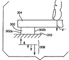
Fig. 2 schematically illustrates the partial cross section figure that passes through based on the touch sensor of power according to an embodiment of the invention;
Fig. 3 A and 3B schematically illustrate the distribution of the power on the force transducer when touching the diverse location of touch-screen;
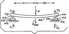
Fig. 4 A schematically illustrate when sensor-robust power is put on when appending to overlayer and supporting construction the situation of force transducer;
Fig. 4 B schematically illustrates the effect of rotation softening (rotational softening) when power is put on flexible overlayer according to one embodiment of present invention;
Fig. 5 A and 5B be offer curves figure respectively, illustrates from the estimation output of force measuring system and for the softening output error that goes up function of position as screen of the rotation of different condition;
Fig. 6 A schematically illustrates the distortion of mounting structure when firmly clamping force transducer between overlayer and structure;
Fig. 6 B schematically illustrates the distortion of mounting structure when existing rotation softening according to one embodiment of present invention between structure and overlayer;
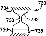
Fig. 7 A-7G schematically illustrates the different embodiment that comprise according to the softening force sensor units of rotation of the present invention;
Fig. 8 A and 8B schematically illustrate another embodiment that comprises according to the softening capacitive force sensor of rotation of the present invention;
Fig. 9 A and 9B schematically illustrate another embodiment that comprises according to the softening capacitive force sensor of rotation of the present invention;
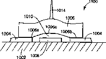
Figure 10 schematically illustrates another embodiment that comprises according to the softening capacitive force sensor of rotation of the present invention; And
Figure 11 A-11C schematically illustrates another embodiment that comprises according to the softening capacitive force sensor of rotation of the present invention.
When the present invention is suitable for the various modifications and the form of replacement, details of the present invention is shown, and will be described in detail by the example in the accompanying drawing.Yet, should be appreciated that the present invention is confined to described specific embodiment to the present invention.On the contrary, the present invention includes all modifications, the equivalence and alternative that drops in the spirit and scope of the present invention that define by appending claims.
Describe in detail
The present invention can be applicable to touch detection technical, believes that for reducing illeffects be useful especially, and described illeffects is to take place when the structural bending of touch panel overlayer or installation touch panel.For example, can in desk-top, hand-held or laptop computer system, point of sales terminal, electronic organizers (PDA) or cell phone, use touch-screen of the present invention.Describe though combine, if necessary, can combine touch panel device of the present invention with the system of any logic-based based on the system of microprocessor.The present invention is directed to the touch location of determining on the touch-screen.One or more touch sensors of pressing close to the touch-surface of touch-screen by the position produce the touch signal that expression acts on the touch force on the touch-screen.Can obtain touch signal from single-sensor, or obtain touch signal by the component touch signal that makes up from two or more force transducers.Definite component force signal that needs to analyze the touch panel sensor generation of touch location.
Especially, the present invention is directed to according to being applied to force measurement on the screen and determine the touch-screen of touch location.Screen overlayer in this touch-screen can show very hard to the user, still can be crooked but compare with the rigidity of the sensor that supports them.Especially, overlayer can be with respect to the torsional motion of sensor and bending.In other words, sensor can suppress to be right after near the tectal bending it, simultaneously the moment that is associated with this inhibition action is sent to support.On the contrary, trend towards making the bending of the support that sensor twists a little from its normal perpendicular positioning may force the overlayer part following bending.This also may be accompanied by by sensor and send bigger moment.These moments may have problems, and wherein, these moments cause that vertical force additional in the sensor keeps balance.The vertical touch force distortion of expection that this makes sensor may cause the error reporting of touch location.
The existing method that reduces these problems trends towards strengthening the overlayer of rigidity and/or the sensor of rigidity.Under the contrast, the present invention is directed to and use the coupling that is called " rotation is softening " between overlayer and the sensor, so that the moment that produces from crooked overlayer can not put on sensor.This has reduced the error that produces from the photostat in response to moment, has also reduced the vertical force of describing just now of looking genuine, and therefore can reduce the problem of error reporting touch location.
The basic element of character with device 100 of touch display shown in Figure 1.Below touching parts 104, place display unit 102 as LCD (LCD) or cathode ray tube (CRT) etc.Display unit 102 is coupled to processing unit 106, and shows the information that receives by display controller 108 from processing unit.Display controller 108 can be the part of processing unit 106.By can being that the touch screen controller 110 of the part of processing unit 106 is determined at the touch location that touches on the parts 104.Therefore, can make processing unit 106 determine to touch on the parts 104 the touch location with respect to shown image on the display unit 102 and the meaning of definite user's input.In order to guarantee that processing unit 106 receives desired information from the user, make in the error that touches determined touch location on the parts 104 is very important as far as possible for a short time.
A kind of specific type that touches parts 104 comprises overlayer and the many sensors that the user pushes, with the power of determining that each position produces on overlayer.Can determine touch location by analyzing the power that is detected then.Shape at touch-screen is under the situation of rectangle, and four sensors are arranged usually, and sensor on each angle is to measure applied force.In certain embodiments, force transducer can be positioned at the back of display itself to be supported, and display itself works to touch parts.In this case, itself has substituted overlayer display pannel, and display pannel sends to force transducer to applied force.
Generally, force transducer detects certain motion that produces according to applied force.For example, applying under the situation of power, strain gauge element stretches, and when compression or stretch sensor element, the electrical characteristics of piezoelectricity or piezoresistance sensor change.In addition, in capacity sensor element, when applying power, a capacitor board moves with respect to another piece capacitor board.Therefore, though can refer to sensor to be displacement transducer,, still can cause the applied force of measured displacement with the measurement estimation of displacement even be appreciated that also the amplitude of displacement itself is very little.
In the U.S. Patent application 09/835,040 that proposes April 13 calendar year 2001, describe an embodiment of the force transducer that is suitable for touch-screen applications, quoted described patented claim here as a reference.This force transducer is suitable for using with LCD (LCD), cathode ray tube (CRT) or other transparent display, schematically illustrates in Fig. 2.In this specific embodiment, sensor is measured applied force according to the electric capacitance change of capacitive element.
Make touch parts or overlayer 210 be arranged in structure or shell 215.Can make this structure or shell 215 have big central aperture, can watch display by this aperture.In addition, overlayer 210 can be transparent so that allow this watching.If desired, the lower surface of shell 215 is directly installed on the border of the useful area that centers on it facing to the surface of this display.In another embodiment, as mentioned above, can substitute overlayer with the structure that comprises display unit such as LCD.
Can be placed on capacitive sensor 220 between overlayer 210 and the shell 215.Can be couple to shell 215 to the interconnection 225 that has connection pads (land) 233 by welding, bonding or other method.Conducting region forms first transport element 234 in the interconnection 225.For example, can append to second transport element 235 on the pad 233 of interconnection 225 by welding with central protrusion 240 (for example, ripple).By the shaping of second transport element 235, or, between first transport element 234 and second transport element 235, form little gap 280 by second transport element 235 being appended to the technology of interconnection 225.For example, the width in gap 280 is near 25 μ m.The transport element 234,235 that separates by gap 280 forms a capacitor.
Can be inserted in the pressure-bearing surface of selecting for use 270 between the touch pad 210 and second transport element 235.Can protect overlayer 210 not to be subjected to protrusion 240 delineations or damage like this, particularly constitute in the tectal situation with softer material.Can also install to overlayer 210 to bearing surface 270 by the thin layer of thin layer of elastic material (not shown) or extremely soft binder, thereby horizontal softening function is provided.Be appreciated that in normal running overlayer 210 or pressure-bearing surface 270 are to contact protrusion 240: for clarity, these elements separately illustrate.
Second transport element 235 combines the function of spring and condenser armature.When vertical force being put on touch pad 210 surperficial, 235 bendings of second transport element reduce the width in gap 280, and have increased the electric capacity of sensor 220.Can measure the variation of this electric capacity, and make it relevant with the power that is applied to touch pad 210.Though described the touch-screen that uses capacitive force sensor, can use the force transducer of other type by similar mode, for example, piezoelectric sensor and strain-gage pickup.
Based on one of advantage of the touch-screen of power is to place the optically distinguishing layer of the less number of plies between display unit and user.Generally, the overlayer that is placed on the display unit is single-glass or the polymkeric substance that suitable rigidity is arranged, and for example, polycarbonate etc. can be selected by suitable optical quality.Compare with the touch-screen of other type such as resistive or capacitive touch screen, need several layers of layer that has optical loss on the display unit of these touch-screens.The conductive film that needs in resistive or capacitive touch screen generally has higher refractive index, and causing is increasing reflection loss at the interface.When having other solid/air interface and when anti-reflection coatings is useless, this is a special problem in the resistive screen, contacts because conducting stratum must can carry out physics.Yet, only having its upper and lower surface based on the flat overlayer of the touch-screen of power, can handle to reduce reflection loss and to reduce dazzle these surfaces.For example, can provide overlayer to reduce direct reflection, and/or can provide overlayer to reduce reflection loss with anti-reflection coatings with rough surface.
Though more need the overlayer that approaches, thin overlayer is than the easier bending of thick overlayer.The present invention is that very hard or approaching very hard former method forms contrast with the supposition overlayer.Except only being the reason for size and weight, require overlayer that flexible is arranged.For example, when the device below touch-screen when being flexible, any angle that is positioned at following device all can cause the distortion of display to the distortion at angle.This trends towards forcing pair of sensors relative on the diagonal angle upwards pasting overlayer, and other a pair of pulling down.Flexible overlayer is positioned at following device and complies with this distortion of reversing by leniently following, and does not damage and has reduced negative effect.
Because excessively hard overlayer makes so crooked failure can cause some problem.There are some problems in many possible sensor configuration, but only consider the situation of four loaded contact angles here.Along with increasing twisting resistance, at first prevent displacement, and all twisting resistances will show as on the vertical component that is superimposed upon sensor measurement by tectal rigidity.Often, these power are greater than general touch force, and have fluctuating.These power can make force transducer be in outside their reach.Further increase twisting resistance, one of sensor possibility complete discharge exposes the space between sensor that unloads and overlayer.Therefore this space correlation can cause bigger parasitic capacity (parasitic force) by the annex of any other type between sealing, installation or cover layer edges and the surrounding structure in supporting construction or with respect to the rising or the whereabouts of the screen of cover layer edges.These effects can cause the false readings of touch location.We get back to and consider how the crooked transmission that how to cause moment, transmission of torque cause measuring error and how to prevent the two with rotating to soften now.
A moment can be put on the sensor of following support bends.For example, this may come from touch force of appropriateness is applied on the in fact light and not expensive supporting construction.When applying external force, being positioned at following supporting construction also can be crooked, irrelevant with pre-prepared touch on the cover surface.For example, the user can rest his or her hand on the angle of screen, or the little power distribution equipment with touch-screen can be positioned on the crooked floor.When passing through sensor passes from the moment of overlayer bending, this moment that takes place by support bends also needs parasitic vertical power to keep balance.
Except these errors, some sensor corresponds directly to the moment that applies, and causes further error.This is owing to cause in response to the vertical force different piece transmission, that homogeneity is relatively poor by sensor.
Can use rotation softening, i.e. the incompatible minimizing of the decoupling of the revolving force between overlayer and the sensor is read by the power that mistake is arranged that above-mentioned arbitrary effect causes.The softening relative pattern that allows to take place identical internal stress in sensor of rotation is no matter touch to be positioned at where touch parts.
Get back to Fig. 2 once more, protrusion 240 provides little contact region for sensor 220 on pressure-bearing surface 270.In addition,, and just pressure-bearing surface 270 is rested on the protrusion 240, then when overlayer 210 distortions, do not have transmission of torque to arrive sensor 220 if protrusion 240 is not appended on the pressure-bearing surface 270.Yet when overlayer twisted, sensor 220 is detection of vertical power still.Further specify this rotation uncoupling between overlayer and the force transducer below.
Sensor also can be in response to the shear that is applied.The sensitive axes that the shear response is expressed as sensor can be not orthogonal to its mounting plane.In the system that does not divide power path (divided force path), site error is directly proportional with the long-pending of sine that tangential force multiply by error angle (angle of sensitive axes from vertical off setting to the touch plane).Touch the plane and be overlayer that the user touches or the plane that touches parts.Dividing power path is to transmit the path that is parallel and perpendicular to the power that touches the plane, sees No. the 09/835th, 049, the U.S. Patent application that is entitled as " Tangential Force Control InA Touch Location Device ", quotes as a reference here.For example, when installation surface is not parallel to the touch plane, or when the uneven binder layer of used thickness sensor installation, when sensor installation itself, can synthesize this error angle by any error.
Rotation is softening not only to have reduced the moment that bending that sensor exposed overlayer or installation surface causes, but also reduces the occurrent sensor moment that is caused by shear.This can realize by the softening rotation center of rotation being obtained as far as possible the center of proximity transducer itself.
The use that divides power path has been discussed in No. the 09/835th, 049, U.S. Patent application.The branch power path reduces the tangential force that puts on sensor.Tangential force is parallel to the touch plane.Implement to divide a power path, and can ignore tangential force by sensor the time, also do not existing to act on above the sensor or the distortion moment of the softening pericentral tangential force of following rotation.In this case, rotation softening for reducing because the tectal bending of touch pad moment that cause, that directly put on sensor is useful.It is softening to implement rotation at any proper height place with respect to sensor or touch plane.When laterally not softening, then having to be beneficial to provides rotation to soften the negative effect that reduces transverse force in the plane that touches the plane.
Describe a kind of method that can put on moment sensor with respect to Fig. 3 A and 3B, described accompanying drawing is illustrated in the distribution of contingent power in the sensor, especially when sensor 302 is stronger than the rotation rigidity of overlayer 304.As seeing in Fig. 3 A, the power F that directly puts on the sensor may cause uniform stress distribution 306.In Fig. 3 B, power F ' is put on overlayer 304 on the point on the sensor limit, cause uneven stress distribution 308.The sensor (not shown) of an opposition supports another edge of overlayer 304.To leave sensor 302 farther though touch the sensor ratio leave this opposition, can be by the sub-fraction of the sensor passes touch force F ' that opposes.Yet in shown situation, the bending of overlayer 304 has the effect of the load of removing the opposition sensor, causes the nearly all touch force F ' by sensor 302 of cantilever support.This causes the pressure at the nearside 302b place of sensor 302, and at the tension force at 302a place, the distally of sensor 302, and this power may be the manyfold of the mean value of the power value measured of requirement.
When the power of accurately offsetting distributes part may be more much bigger than the signal of measuring the time, measuring exactly that this power distributes 308 is difficulties.If sensor surface is not fixed to overlayer 304 and supports on 310, then do not have tension force, but the stress distribution 308 of the nearside 302b of proximity transducer 302 becomes more concentrated.This causes the response in the sensor and the similar problem of dynamic range unevenness.Yet,, just reduced these problems if the rotation of the moment by sensor passes occurs reducing at the sensor place softening.
Further describe with respect to Fig. 4 A moment is put on sensor, Fig. 4 A illustrates the overlayer 404 that is supported between two sensor modules 402 and 403.Overlayer 404 is flexible, and it is not a perfect rigidity, can particularly put on crooked away from the power of the strong point according to applied force.Sensor module 402 and 403 is rigidity: for example, can use piezoelectric element to form sensor module.Sensor module 402 and 403 is delivered to support 410 to power and moment.The operator F that exerts oneself
TotalBy being pressed on the overlayer 404.Power F
1Be delivered to support 410 by first sensor assembly 402, and power F
2Be delivered to support 410 by second sensor module 403.When balance, F
Total=F
1+ F
2Reacting force F
1' (=-F
1) and F
2' (=-F
2) produce moment on every side at the P point that applies power.Since the rotation rigidity of sensor, moment m
1Can transmit by first sensor 402, and moment m
2Can transmit by second sensor 403.
When balance, moment and power are eligible:
F
1*x
1-m
1=F
2*x
2-m
2 (1)
Wherein, x
1Be the distance of ordering from first sensor 402 to P, and x
2It is the distance of ordering from second sensor 403 to P.Should be noted that here in the formula of expression, by variable on the occasion of representing variable, though other notation convention also is possible.
Though simple power-senses touch location means does not produce direct representation m
1Or m
2Signal, but these moments influence the force signals that sensor 402 and 403 produces really.Can use the indirect method of attempting to estimate or proofread and correct these moments, be difficult to carry out though these methods are complicated.Yet, do not implement these methods, serious error may take place in position calculation.
The another kind of method of the measurement touch location that comprises that rotation is softening schematically is shown in Fig. 4 B.In this method, support flexible overlayer 404 between two sensors 412 and 413.Sensor can be the sensor that detects any kind of the power that applies, for example piezoelectric sensor, capacitive character displacement transducer, piezoresistance sensor or strain-gage pickup etc.
Between overlayer 404 and each sensor 412 and 413, rotate freely bearing (rotationallyfree bearing) 414.For example, laterally softening thing 416 can also be arranged between support 410 and sensor 412 and 413.Can constitute laterally softening thing 416 with the material that allows to be convenient to lateral elastic motion, so that tangential force is not delivered to support 410 by sensor 412 and 413.In No. the 09/835th, 049, U.S. Patent application, further described laterally softening thing.
The P point of user on overlayer 404 applies F
TotalCause passing through sensor 412 and 413 respectively power F
1And F
2Be applied to and support 410.Reacting force F
1The F of '=-
1And F
2The F of '=-
2Around the P point, produce moment.Because the not direct carry-over moment of the softening sensor module 412 and 413 of rotation is passed through F around the P
1' and F
2' moment that produces must be the resultant couple around the P, when balance, this is zero.Therefore, we can write out formula:
F
1x
1=F
2x
2 (2)
Therefore, when sizable flexibility in overlayer, occurring, can use this simple relation according to the softening use of rotation.
Fig. 5 A and 5B illustrate the performance of using formula (2) to come the various systems of calculated touch location.Definition horizontal ordinate " x " is mark (fractional) position that the actual P between the force transducer is ordered:
x=x1(x1+x2) (3)
In Fig. 5 A, ordinate is the estimated value of system's output " x ".In Fig. 5 B, ordinate is the fraction error in the estimated value of " x ".Can obtain percent error by fraction error being multiply by 100.
In each case, institute's system for simulating is simplified, and wherein overlayer 404 is to support parts that extend between the sensor module at two.These parts that adopted are narrow as to be enough to handle as simple beam (beam), and adopt sensor module simple support to be provided or to clamp support.During operation, the actual touch structure seldom has the half thickness that is displaced to them, if any, then makes to touch offset dwell in the beam scope.Further make parts keep uniform rigidity along its length.Then, estimate easily the system that produced.
The output of situation about supporting simply two ends is free from error, and provides by the line of dividing subtly among Fig. 5 A 502.In Fig. 5 B, institute's error of calculation is shown with curve 512.This is corresponding to the flexible overlayer configuration of Fig. 4 B.Response curve 502 also is similar to have enough thick and a response curve quite hard tectal real system.So overlayer has overwhelmed the rotation rigidity that sensor connects and be positioned at following support.In the tectal limit of infinitely great rigidity, response curve becomes a straight line fully.When hard overlayer was connected to flexible a little support by rotation rigidity sensor, response curve may be at a slight tilt and be offset.Yet, when curve keeps straight line, can remove this potential error by correction or registration technology commonly used.
Yet, have can moderate bending overlayer the time, the sensor of common rotation rigidity and install and can cause bigger nonlinear response.When the rigidity of sensor is stronger than tectal rigidity, describes resulting response by the block curve in Fig. 5 A 504, and come description error by the block curve among Fig. 5 B 514.More resemble Under water plate and support the frogman touch, and the power of the small scale that is expected at other sensor place is further reduced near zero by the sensor support proximity transducer.
Can observe, it is less can be used for distinguishing susceptibility proximity transducer, nearer touch at interval.Therefore any trial in calibrated calculating all can be in the face of the noise in these zones and the difficulty of precision.
The curve of widely dividing among Fig. 5 A 506 is described the response of a system, and wherein, left sensor provides simple support, and one on right side is continued to provide and clamped support.Can from then on see, for favourable, the reasonably limited softening measure of rotation of balance preferably.A sensor in only softening two sensors makes error worse rather than better in fact, shown in curve 516 corresponding among Fig. 5 B.
When the bidimensional cover surface considering to be supported on several sensors (for example, four sensors), obtain following difference for rotation rigidity sensors coupled and flexible tectal effect.Site error becomes the complicated function of X position and Y position.Owing to existing downward a little ripple to make error figure further complicated around the touch-surface that touches contact point.Though by immediate sensor passes most power, than low value and more the some place of proximity transducer maximum error may appear.Increase the outside carry-over moment in cross section of the covering layer material of area from sensor by increasing radius, this provides excessive inherence rotation to soften for the touch away from sensor.
Another possible error source in determining touch location is to be in to trend towards twisting in the state of one or more sensors when sensor fixing structure itself is crooked.This state schematically is shown in Fig. 6 A.When the device that holds touch-screen was subjected to external force, structure 610 can be twisted under sensor, for example,, on non-horizontal direction, use if this device is kept a firm hand in user's hand, or the edge of user's press device.
In the embodiment shown in Fig. 6 A, suppose that sensor module 602 is to rotate rigidity with respect to overlayer 604.Structure 610 is twisted angle φ 1, and overlayer is twisted the 1 approximately uniform angle φ 2 with φ.
Cause moments of power distribution 606 generations that are associated in the sensor 602 by the structure rotation of φ 1.Power+the F that sees by sensor 602 and 603 and-F ' comes this moment of balance.These power+F and-F ' introduces the error of touch location.Owing in sensor signal, may not predict the information that the installation site changes, so the error that is associated may be uncorrectable.
In the embodiment shown in Fig. 6 B, sensor module 612 and 613 is that rotation is softening with respect to overlayer 604.Sensor module 612 and 613 can comprise softening thing 612a of rotation and 613a separately.Provide rotation the softening other example of thing below.
When making structure 610 angle of bend φ 1, the angle φ 2 of the overlayer 604 that is produced is significantly less than φ 1, so ratio psi 2/ φ 1 is less.Any residue rigidity in the softening thing 612a of rotation may produce the little nonzero value of φ 2.So, will make from forcing the error that rotation is installed to reduce ratio psi 2/ φ 1.For the configuration of some requirement, the less value that is controlled at the φ 1 that can run in the application of touching device fabricator.In these situations, it may be best rotating freely and detect connection.Be noted that importantly that in this case the rigidity that increases overlayer 604 can not reduce error, in fact may increase error.
Be appreciated that less φ 2/ φ 1 ratio is associated with the various less touch location error of kind that Fig. 3 describes.When this error is preponderated, can determine that need only φ 2/ φ 1 under particular value, flexible overlayer just can provide enough touch positional accuracies.
A specific examples of the softening sensor of rotation shown in Figure 2.The protrusion 240 of capacitive force sensor 220 is not appended on the overlayer 210, so overlayer 210 can be with respect to sensor 220 distortions and to sensor 220 carry-over moments.
Fig. 7 A-7G is depicted as touch sensor provides some softening diverse ways of rotation.Fig. 7 A-7C schematically illustrates two fulcrums, the softening sensor unit 700,710,720 of rotation.These sensor units can provide laterally softening and rotation softening, and can use, as described in No. the 09/835th, 049, the U.S. Patent application together with the lateral stiffness thing.
Be included in point element 702 or swivel bearing between overlayer 704 and the power fan diffuser 706 in the first sensor unit 700 shown in Fig. 7 A, described power fan diffuser is diffused into applied force and can be placed on fan diffuser 706 and supports sensor element 708 between 709.The effect of fan diffuser 706 is also as the container of point element 702.
Sensor unit 710 comprises the first fan diffuser/container 716a that is attached on the overlayer 714 and is attached to second power fan diffuser/container 716b on the sensor element 718.Point element 712 is placed between two fan diffusers/container 716a and the 716b, sensor element 718 is appended to support on 719.
Sensor unit 720 comprises the first fan diffuser/container 726a that is attached on the sensor element 728.In this specific embodiment, sensor element 728 is placed between fan diffuser/container 726a and the overlayer 724.Second power fan diffuser/container 726b is installed in the support 729.Point element 722 is placed between two fan diffusers/container 726a and the 726b.
Synoptic diagram illustrates sensor unit 700,710 and 720 and uses the point element 702,712 and 722 that narrows down gradually, and the contact radius that diminishes gradually, though not necessarily like this.In some assembly, have the more miniaturization of point element of narrower aspect ratio, and less contact radius can reduce that foreign particle pollutes and the chance that influences quiet run.
Can be used in the quite hard material that can significantly not be out of shape under the pressure that keeps overlayer and structure and constitute point element 702,712 and 722.For example, can use metal, glass or hard polymkeric substance to constitute point element 702,712 and 722.Equally, can be used in the material that can significantly not be out of shape under the pressure and constitute container 706,716a, 716b, 726a and 726b, and can constitute with metal, glass or polymkeric substance.If be used for material significantly distortion under pressure of point element or container, then the surface area of contact increases, thereby has reduced the rotation emollescence.
Fig. 7 D-7G schematically illustrates the softening sensor unit of the dissimilar rotation that can append to overlayer and mounting structure.These sensor units generally need the bending of material, and described material configuration becomes to provide real rotation plasticity.
Use the coupling block 732 that is placed on the material between overlayer 734 and the sensor element 736 at the sensor unit shown in Fig. 7 D 730.Sensor element 736 is installed in and supports on 738.Coupling block 732 has narrow waist 733, makes the round end of the piece 732 that is installed to overlayer 734 relative with the end of the piece 732 that is installed to sensor element 736.Thickness and desired rotation softening degree according to coupling block 732 narrows down can constitute piece 732 with the material with quite high Young elasticity coefficient.For example, coupling block 732 can be the block of material such as metal or duroplasts, and the extruding back forms waist 733, or the distortion back forms waist 733.
Comprise the sensor element 746 that is installed on the structure 749 at the sensor unit shown in Fig. 7 E 740, and the coupling block 742 that is installed to the low elasticity coefficient material (for example, tartan) of overlayer 744.Coupling block 742 can be than having more moderate aspect ratio at the coupling block 732 shown in Fig. 7 D.Can directly be installed on sensor element 746 to coupling block 742, maybe can by shown in power fan diffuser 748 be installed to sensor element 746.In this specific embodiment, sensor element 747 is directly to be installed to support 749.
The sensor element 756 that comprises the power of transmitting in response to shear rather than extruding at the sensor unit 750 shown in Fig. 7 F.Can directly append to overlayer 754 to sensor element 756.The coupling block 752 of low elasticity coefficient material (for example, synthetic rubber) can be connected to the sidewall 759 of supporting construction.Can directly append to coupling block 752 on the sensor element 756, or append on the sensor element 756 by power fan diffuser 758.
The order that is appreciated that the element in sensor unit must be not as shown in the figure.For example, can append to overlayer 744 to the sensor unit among Fig. 7 E 746, simultaneously coupling block 742 be appended to structure 749.Generally, when coupling block hour, they have lower rotation rigidity, have slenderrer aspect ratio, and/or are made of the material with low Young elasticity coefficient.
The material that the one deck that quite approaches in 760 uses of the sensor unit shown in Fig. 7 G can highly push is such as opening micropore (open-cell) or closed micropore (closed-cell) foamed material, as the softening coupling block 762 of rotation.Coupling block is installed on overlayer 764 and the sensor element 766.Sensor element 766 is installed in the support 769.
When the coupling block material clip was between two rigid surfaces, the compressibility of the air in the foamed material of coupling block 762 had been avoided a contingent difficult problem.When one of surface during, compressed material, and trended towards being out of shape with serious shear at piece one end place with respect to another surperficial rotation.This is because the material of non-porous low Young elasticity coefficient generally is isopyknic, and has about 0.5 Poisson ratio.When piece is in the tension force that stretches between two surfaces of having separated, at this part material place opposite problem takes place.Net effect is that rigidity increases significantly when the piece attenuation, is just provided by coefficient of cubical elasticity basically up to plasticity.
Another method of removing sensor and coupling by overlayer and structure applied force square is to use little contact point not append to the sensor of contrast surface.For example, in Fig. 2, protrusion 240 contacts, but do not append to, on the overlayer 210.Be appreciated that little contact point also can contact structures and do not contact overlayer.
The additional embodiments that the softening capacitive force sensor of rotation is provided is described now.At first, constitute a specific embodiment of force transducer 800 in fact with plane supporting part 802 with reference to figure 8A and 8B.Form electrode pattern on support component 802, it comprises one or more first electrodes 804 that are connected to spring members 806, and at least the second electrode 808.Best, spring members 806 mechanically is springy, conducts electricity on electric.For example, can form spring members with a kind of metal or with the insulator such as plastics of coated with conductive thing.Can use any suitable method that support component 802 is seated on the following supporting construction 820.For example, can use acrylic acid band 822 that support component 802 is installed, make it the isolation that provides laterally softening and crooked.
Between the spring members 806 and second electrode 808, form capacitance gap 810.A kind of method that forms the gap is formed in the spring members 806 that each end has skew a little, as shown in the figure.In another approach, can form the spring members 806 that does not have this skew, and by separating spring members 806 with interim washer and second electrode 808 is made gap 810, then, with the connection between solder reflow first electrode 804 and the spring members 806.In another approach, can use the scolder that comprises specific sized particles to make the spring members 806 and first electrode 804 have and form gap 810 at interval.
When the following spring members 806 of the effect of power is pressed onto on the overlayer 812, reduced the width in gap 810, therefore changed measured electric capacity between first and second electrodes 804 and 808.Discrete lead 814 provides being electrically connected between touch controller circuit and electrode 804 and 808, to allow the electric capacity of survey sensor 800.
The fulcrum mechanical axis that spring members is furnished with the ridged formula holds 816, and this structure has advantageously provided good intensity and resisted load extremely.
In a particular embodiment, can be wide with about 250 μ m thick (10mil) and about 6mm the spring steel of (0.25 ") form spring members 806.Spring members is about 17mm long (0.75 ") drawing on mould.Capacitance gap 810 can be about 125 μ m (5mil).Can use any suitable material such as the expoxy glass printed circuit board to form support component 802.Support component 802 generally has enough rigidity, can the laterally softening thing such as acrylic acid band 822 be placed between support component 802 and the structure 820.The non-loaded electric capacity of this structure is about 3pF, and the power that touches the end is between about 4 and 5 pounds.Be appreciated that the size and the material that are provided just are used for explanation, in no case should be as restriction.Should select the size of sensor element according to the characteristic of the specific touch device that will construct.
The advantage that this structure provides is, as fruit structure 820 bendings, therefore the crooked support component 802 that is delivered to that is produced has reduced the effect to measured power of the power that comprises relatively poorly.
With reference now to Fig. 9 A and 9B,, another embodiment 900 of capacitive sensor comprises the spring members 906 with outwards outstanding ripple 916.Fig. 9 A is schematically illustrated in the sensor 900 of original position, and Fig. 9 B provides the exploded view of sensor 900.
Spring members 906 is installed in the support 902, in support 902, provides the electrode pattern that comprises one or more first electrodes 904 and second electrode 908.Spring members 906 is connected to first electrode 904, but be spaced from, for example uses to top with respect to similar technology one of in the sensor 800 described technology.Between the spring members 906 and second electrode 908, form capacitance gap 910.
Can be placed on laterally softening thing 920 between ripple 916 and the overlayer 922 to provide laterally softening.Support component 902 is installed on the structure 924.
In a specific examples of sensor 900,, about 3mm (120mil) wide spring steel long by 150 thick, the about 6mm of μ m (6mil) (230mil) constitutes spring members 906.Can constitute spring members 906 by other material and the material with different-thickness.For example, can constitute spring members 906 by the thick phosphor bronze of 200 μ m (8mil).Capacitance gap 910 can be 25 μ m (1mil) height.Use load on spring center punch press to form bearing ripple 916, push spring members 906 facing to the backing that such as aluminium, quite can be out of shape simultaneously.The free span of spring members is about 3.75mm (150mil), and its central 2.15mm (86mil) is facing to second electrode 908.The non-loaded electric capacity of sensor 900 is about 3pF, and the power that touches the end is between about 3 and 4 pounds.
Capacitive force sensor represents the function of the variation of capacitive reactance as the variation of applied force.For sensor 800 and 900, this changes and hour less power to be come down to linear at relative gap.Yet, for bigger power, the center closure of capacitive region, the edge keeps wideer interval simultaneously; This causes the non-linear decline of capacitive reactance to become faster than linearity decline.In the processing of sensor signal, can realize compensation to this non-linear response characteristic.In another approach, can provide the embodiment of various capacitive sensors, they have inherent bigger linear capacitive reactance variation range.Therefore, in addition when one or more condenser armatures according to applied force and when crooked, the capacitive force sensor with inhomogeneous gap also can provide improved measure linear degree with simple signal Processing.
A specific embodiment that has through the capacitive sensor of extended linear response range schematically is shown in Figure 10.In the drawings, exaggerated the size on the vertical direction, to clearly show that sensor 1000.Sensor 1000 has the spring members 1006 of the controlled shape system of slight curvature.The crooked permission appends to first electrode 1004 to the end 1006a of spring members 1006 and 1006b with minimum welding film, and core 1006c provides the capacitance gap 1010 with respect to second electrode, 1008 maximums simultaneously.Supporting formation first and second electrodes 1004 and 1008 on 1002.The grade that can be applied to the power on the male part 1014 just in time is enough to make spring members 1006 beginnings to contact with second electrode 1008.Can so form the slope of the capacitance gap 1010 between the spring members 1006 and second electrode 1008, make at many somes place to come in contact simultaneously along second electrode 1008.This has reduced the non-linear of sensor response.In No. the 09/835th, 040, U.S. Patent application, this sensor has been described in more detail.
As shown in Fig. 8 B and the 9B, the spring members of capacitive force sensor must not be a rectangle, and must not form by homogeneous thickness.For example, can form the spring members shape, thus make especially bending concentrate on desired, not in the zone as condenser armature.This has reduced the bending in capacitor regions, has therefore increased the linearity that capacitive reactance changes.The other shape and the formation of spring members further have been discussed in No. the 09/835th, 040, U.S. Patent application.
Use can form capacitive sensor by the spring members of the insulating material manufacturing of or some regional coated with conductive material regional at certain.A specific examples of this sensor 1100 is described with reference to figure 11A-11C.For example, material 1102, a zone of expoxy glass printed circuit board forms main element 1106.Main element 1106 comprises weld zone 1107 and 1108, and this part storage of expoxy glass substrate changes the significant elastic energy that is associated with capacitance gap.
The schematic section that provides from Figure 11 B can be clear that, predefined path from overlayer 1114, is closed the central area 1122 that cushion 1116, last condenser armature 1118 and interval/connection welding film 1120 take main element 1106 to applied force by couple of force.Groove 1124 is positioned at the side of middle section 1122, and the effect of groove 1124 is the bendings in the increase and the printed circuit board substrate that relatively localizes.The end of groove 1124 is transmitted out and centered on to power, arrives at last and support 1126.When leaving with capacitive region and groove 1124 close vicinity when the power transmission, therefore it is relevant with the variation brought out by power in the capacitance gap that any additional bending all stops, no longer by the force transducer transmission.Be installed on the structure 1128 supporting 1126.
If present, the support 1126 that is placed on the proximity transducer place can be played some effect for the symmetry of susceptibility and response.Can give this near the layout that supports symmetry, such as shown, not excessively near central area 1122.Can place farther support by the figure of any needs.
Cushion 1116 provides laterally softening and rotation is softened both.Therefore, pad 1116 can provide the function of ripple 914 and laterally softening thing 920.Can be tightly bonded 1116 and be affixed to following last condenser armature 1118, but above non-cohesive.Then, can aim at such as the structure above overlayer 1114 sensors such as grade 1100, and carry out prestrain.In another approach, pad 1116 provides the possibilities of keep aiming at, and handle component be attached to by stick above and below.
Another embodiment 1150 that schematically illustrates in Figure 11 C illustrates the power path of a change, and this path is by the length transmission of last condenser armature 1118.Can make the container panel 1118 that powers on store significantly effect now for the elastic energy that is associated with capacitance gap; In this case, can suitably regard last condenser armature 1118 as with following main element is an additional spring members 1106a of spring members 1106 collaborative works.Power, continues around groove 1124 and to central area 1122, again from there to supporting 1152 by welding 1130 spring members 1106 below being delivered to from additional springs parts 1106a.
Be appreciated that the many changes on capacitive force sensor of the present invention are possible.In No. the 09/835th, 040, U.S. Patent application, these have been done further discussion.An example in the change of embodiment discussed herein be can fulcrum append to tectal below rather than append to the spring members of force transducer.In another change, can sensor be installed to tectal below, and fulcrum contacts with stayed surface.
As mentioned above, the present invention can be applicable to touch sensor, believes for relying on the touch sensor of measuring the power that puts on touch sensor particularly useful.Should not be considered as the present invention and be confined to above-mentioned specific example, comprise all aspects of the present invention of clearly stating in the appending claims but be construed as.By reading this instructions, the present invention at those skilled in the art that can easily understand the present invention can applicable various modifications, processing and many structures of equivalence.Plan comprises this modification and device with claims.
Claims (9)
1. one kind is used for determining that one touches the device of the position on touch-screen, comprising:
Flexible touch parts, it can respond described touch and move;
Supporting construction;
A plurality of sensor units, they are positioned at each sensor regions place of described touch parts, and be coupling between described supporting construction and the described touch parts, each sensor unit is measured the signal of expression by the touch power that causes and pass through that each respective sensor district transmits, wherein the signal measurement result who is obtained by each sensor unit is used for determining the position of described touch on touch-screen, and the unit of first sensor at least in described a plurality of sensor unit is configured, be used to prevent that the distortion transmission of torque of one of described touch parts and described supporting construction is by the first sensor unit, described sensor unit comprises a swivel bearing, it is coupling between described touch parts and the described supporting construction, to allow the relative rotation between described touch parts and the described supporting construction.
2. device as claimed in claim 1 is characterized in that, described first sensor unit is coupled to described touch parts in a position that touches between the plane of described supporting construction and described touch parts.
3. device as claimed in claim 1 is characterized in that, further comprises a power fan diffuser, and it is placed between a described swivel bearing and the power detecting element, is used for diffusing through the power that described swivel bearing receives on described power detecting element.
4. device as claimed in claim 1 is characterized in that, at least one sensor unit in described a plurality of sensor units comprises a capacitive character power detecting element.
5. device as claimed in claim 4 is characterized in that, described capacitive character power detecting element comprises a spring members, and it separates by a gap and an electrode, and the scope in described gap depends on the value of the power that applies by described sensor unit.
6. device as claimed in claim 5 is characterized in that, described capacitive character power detecting element comprises a bearing, and it can rotate freely at least one direction, and described bearing constitutes a projection of the spring members of described capacitive character power detecting element.
7. device as claimed in claim 1 is characterized in that, further comprises a display unit, it be placed on described touch parts below, be used for showing an image by touching parts.
8. one kind is the method that the touch on the flexible touch-surface positions, and described method comprises:
Measure a signal, that this signal indication is caused by described touch and by the power that a sensor unit transmits, make distortion moment of one of described touch-surface and a supporting construction and in described touch-surface and the institute's supporting construction another isolated simultaneously,
Wherein being used to isolate the described step of twisting moment comprises with a swivel bearing and isolates described distortion moment.
9. method as claimed in claim 8 is characterized in that, further comprises the transverse movement that limits described swivel bearing.
Applications Claiming Priority (4)
| Application Number | Priority Date | Filing Date | Title |
|---|---|---|---|
| US09/835,049 | 2001-04-13 | ||
| US09/835,040 US20020149571A1 (en) | 2001-04-13 | 2001-04-13 | Method and apparatus for force-based touch input |
| US09/835,040 | 2001-04-13 | ||
| US09/835,049 US7183948B2 (en) | 2001-04-13 | 2001-04-13 | Tangential force control in a touch location device |
Publications (2)
| Publication Number | Publication Date |
|---|---|
| CN1502091A CN1502091A (en) | 2004-06-02 |
| CN1270227C true CN1270227C (en) | 2006-08-16 |
Family
ID=27125753
Family Applications (2)
| Application Number | Title | Priority Date | Filing Date |
|---|---|---|---|
| CNB028081218A Expired - Fee Related CN1270226C (en) | 2001-04-13 | 2002-04-12 | Force sensors and touch panels using same |
| CNB028081463A Expired - Fee Related CN1270227C (en) | 2001-04-13 | 2002-04-12 | Touch screen with rotationally isolated force sensor |
Family Applications Before (1)
| Application Number | Title | Priority Date | Filing Date |
|---|---|---|---|
| CNB028081218A Expired - Fee Related CN1270226C (en) | 2001-04-13 | 2002-04-12 | Force sensors and touch panels using same |
Country Status (5)
| Country | Link |
|---|---|
| EP (2) | EP1390908A1 (en) |
| JP (2) | JP2005502103A (en) |
| KR (2) | KR20040060849A (en) |
| CN (2) | CN1270226C (en) |
| WO (2) | WO2002084580A1 (en) |
Cited By (2)
| Publication number | Priority date | Publication date | Assignee | Title |
|---|---|---|---|---|
| CN101859201A (en) * | 2010-06-02 | 2010-10-13 | 深圳莱宝高科技股份有限公司 | Touch input device and electronic equipment |
| US10990180B2 (en) | 2018-04-03 | 2021-04-27 | Fujitsu Component Limited | Tactile presentation device |
Families Citing this family (29)
| Publication number | Priority date | Publication date | Assignee | Title |
|---|---|---|---|---|
| US8488308B2 (en) | 2003-02-12 | 2013-07-16 | 3M Innovative Properties Company | Sealed force-based touch sensor |
| US7109976B2 (en) | 2003-04-01 | 2006-09-19 | 3M Innovative Properties Company | Display screen seal |
| US7148882B2 (en) | 2003-05-16 | 2006-12-12 | 3M Innovatie Properties Company | Capacitor based force sensor |
| CN100381993C (en) * | 2005-02-23 | 2008-04-16 | 刘二中 | Information input apparatus with pressing plate and method thereof |
| CN101000529B (en) * | 2006-01-13 | 2011-09-14 | 北京汇冠新技术股份有限公司 | Device for detecting touch of infrared touch screen |
| DE102007041876A1 (en) * | 2007-09-04 | 2009-03-05 | Vodafone Holding Gmbh | Touch sensitive display device e.g. thin film transistor display, has touch sensitive device provided in viewing direction on display arrangement and on rear side of display arrangement, and actuated by touching display arrangement |
| JPWO2010067537A1 (en) * | 2008-12-08 | 2012-05-17 | シャープ株式会社 | Operation receiving apparatus and computer program |
| WO2010096499A2 (en) * | 2009-02-17 | 2010-08-26 | Noah Anglin | Floating plane touch detection system |
| CN102043501B (en) | 2009-10-26 | 2016-03-23 | 宸鸿光电科技股份有限公司 | The integrated wire arrangement module of power sensor and pressure-sensitive touch control screen |
| KR101124225B1 (en) * | 2009-11-06 | 2012-04-12 | 한국표준과학연구원 | Touch inputting apparatus with integral sensors and method for fabricating thereof |
| CN102096493A (en) * | 2009-12-11 | 2011-06-15 | 佳士得科技股份有限公司 | Load cell touch device |
| US20120120017A1 (en) * | 2010-11-17 | 2012-05-17 | Synaptics Incorporated | System and method for determining object information using an estimated deflection response |
| US20120169612A1 (en) * | 2010-12-30 | 2012-07-05 | Motorola, Inc. | Method and apparatus for a touch and nudge interface |
| JP5647695B2 (en) * | 2011-01-12 | 2015-01-07 | アルプス電気株式会社 | Push-type input device |
| US8720276B2 (en) | 2011-03-24 | 2014-05-13 | Medtronic, Inc. | Moment fraction computation for sensors |
| US9501098B2 (en) | 2011-09-19 | 2016-11-22 | Samsung Electronics Co., Ltd. | Interface controlling apparatus and method using force |
| US9519350B2 (en) | 2011-09-19 | 2016-12-13 | Samsung Electronics Co., Ltd. | Interface controlling apparatus and method using force |
| CN102928008B (en) * | 2012-11-13 | 2015-04-01 | 上海华勤通讯技术有限公司 | Sensor sealing device of mobile terminal and mobile terminal thereof |
| CN104345946B (en) * | 2013-08-06 | 2017-08-29 | 群创光电股份有限公司 | Touch control display apparatus and its alignment methods |
| US10032592B2 (en) | 2013-08-23 | 2018-07-24 | Apple Inc. | Force sensing switch |
| EP3025217A1 (en) * | 2013-08-23 | 2016-06-01 | Tiyqmat Research LLC | Remote control device |
| DE102014019128A1 (en) | 2014-12-19 | 2016-06-23 | Audi Ag | Operating device for a motor vehicle, motor vehicle and method for operating an operating device |
| EP3387402B1 (en) * | 2015-12-07 | 2021-04-07 | EILERSEN, Nils Aage Juul | Load cell |
| CN105827229A (en) * | 2016-03-15 | 2016-08-03 | 歌尔声学股份有限公司 | Pressure sensing module group and system and electronic device |
| CN106445241B (en) * | 2016-10-26 | 2021-03-26 | 京东方科技集团股份有限公司 | Touch display screen, contact identification method and module and touch display device |
| DE102017200595A1 (en) * | 2016-11-15 | 2018-05-17 | Volkswagen Aktiengesellschaft | Device with touch-sensitive freeform surface and method for its production |
| US10635248B2 (en) * | 2018-01-05 | 2020-04-28 | Amtel Corporation | Force sensor mount and related housings and systems that incorporate the same |
| CN110553761A (en) * | 2018-05-30 | 2019-12-10 | 苏州明皜传感科技有限公司 | Force sensor |
| US11379080B2 (en) | 2020-06-05 | 2022-07-05 | International Business Machines Corporation | Automatically correcting touchscreen errors |
Family Cites Families (5)
| Publication number | Priority date | Publication date | Assignee | Title |
|---|---|---|---|---|
| US4355202A (en) * | 1980-12-08 | 1982-10-19 | Bell Telephone Laboratories, Incorporated | Mounting arrangement for a position locating system |
| JPH0228168B2 (en) * | 1984-12-21 | 1990-06-21 | Nippon Denki Hoomu Erekutoronikusu Kk | TATEGATAZAHYONYURYOKUSOCHI |
| GB2180342B (en) * | 1985-08-14 | 1989-10-25 | Alcom Limited | Pressure sensitive device |
| CA2072730A1 (en) * | 1991-09-09 | 1993-03-10 | Richard L. Garwin | Strain-gauge mounting for force-sensing touch-screen |
| DE9203286U1 (en) * | 1992-03-13 | 1992-05-07 | Baltus, Rene, 5303 Bornheim, De |
-
2002
- 2002-04-12 JP JP2002582447A patent/JP2005502103A/en not_active Withdrawn
- 2002-04-12 KR KR10-2003-7013306A patent/KR20040060849A/en not_active Application Discontinuation
- 2002-04-12 EP EP02762052A patent/EP1390908A1/en not_active Withdrawn
- 2002-04-12 KR KR10-2003-7013369A patent/KR20030090732A/en not_active Application Discontinuation
- 2002-04-12 EP EP02719482A patent/EP1382007A2/en not_active Withdrawn
- 2002-04-12 WO PCT/US2002/011453 patent/WO2002084580A1/en active Application Filing
- 2002-04-12 CN CNB028081218A patent/CN1270226C/en not_active Expired - Fee Related
- 2002-04-12 JP JP2002582448A patent/JP2005508533A/en not_active Withdrawn
- 2002-04-12 CN CNB028081463A patent/CN1270227C/en not_active Expired - Fee Related
- 2002-04-12 WO PCT/US2002/011308 patent/WO2002084579A2/en active Application Filing
Cited By (3)
| Publication number | Priority date | Publication date | Assignee | Title |
|---|---|---|---|---|
| CN101859201A (en) * | 2010-06-02 | 2010-10-13 | 深圳莱宝高科技股份有限公司 | Touch input device and electronic equipment |
| CN101859201B (en) * | 2010-06-02 | 2012-06-27 | 深圳莱宝高科技股份有限公司 | Touch input device and electronic equipment |
| US10990180B2 (en) | 2018-04-03 | 2021-04-27 | Fujitsu Component Limited | Tactile presentation device |
Also Published As
| Publication number | Publication date |
|---|---|
| JP2005508533A (en) | 2005-03-31 |
| CN1270226C (en) | 2006-08-16 |
| KR20030090732A (en) | 2003-11-28 |
| EP1382007A2 (en) | 2004-01-21 |
| CN1502090A (en) | 2004-06-02 |
| WO2002084580A1 (en) | 2002-10-24 |
| WO2002084579A2 (en) | 2002-10-24 |
| CN1502091A (en) | 2004-06-02 |
| EP1390908A1 (en) | 2004-02-25 |
| WO2002084579A3 (en) | 2003-09-04 |
| JP2005502103A (en) | 2005-01-20 |
| KR20040060849A (en) | 2004-07-06 |
Similar Documents
| Publication | Publication Date | Title |
|---|---|---|
| CN1270227C (en) | Touch screen with rotationally isolated force sensor | |
| US7190350B2 (en) | Touch screen with rotationally isolated force sensor | |
| KR100997945B1 (en) | Input device and process for manufacturing the same, portable electronic apparatus comprising input device | |
| CN100351761C (en) | Inputting panel apparatus | |
| JP6833795B2 (en) | Touch display module and electronic devices that apply this touch display module | |
| US8270148B2 (en) | Suspension for a pressure sensitive touch display or panel | |
| JP2005526333A (en) | Method and system for identifying a pressed position on a pressed touch screen using calibration parameters to adjust the mechanical distortion of the touch screen | |
| CN1213449C (en) | Touching Panel | |
| CN1285952C (en) | Liquid crystal display device with digitalizer and its producing method | |
| CN1370292A (en) | Acoustic touch sensor | |
| CN1550968A (en) | Acoustic wave touch detecting device | |
| CN107958199B (en) | Fingerprint detection module, display device and electronic equipment | |
| CN215117465U (en) | Touch pad and electronic equipment | |
| CN112445329A (en) | Touch feedback module and touch device | |
| CN107832671B (en) | Display device and electronic apparatus | |
| CN210984090U (en) | Display device | |
| US20180307885A1 (en) | Fingerprint idendification device and electronic device using same | |
| CN109947244B (en) | Display device and tactile feedback method, device and equipment | |
| US10969895B2 (en) | Input device | |
| CN109858313B (en) | Ultrasonic fingerprint identification module, device and electronic equipment | |
| US11954255B2 (en) | Haptic effect device | |
| CN1096387A (en) | Method and apparatus at outside display location touch force | |
| JP2015018368A (en) | Display device with pressure-sensitive touch input member | |
| US20210048339A1 (en) | Sound inspection method and inspection apparatus for display device including sound generator | |
| JP3728736B2 (en) | Touch panel |
Legal Events
| Date | Code | Title | Description |
|---|---|---|---|
| C06 | Publication | ||
| PB01 | Publication | ||
| C10 | Entry into substantive examination | ||
| SE01 | Entry into force of request for substantive examination | ||
| C14 | Grant of patent or utility model | ||
| GR01 | Patent grant | ||
| C19 | Lapse of patent right due to non-payment of the annual fee | ||
| CF01 | Termination of patent right due to non-payment of annual fee |