CN1270040C - Solar-cell roof, its forming method, photoelectric generating device and building thereof - Google Patents
Solar-cell roof, its forming method, photoelectric generating device and building thereof Download PDFInfo
- Publication number
- CN1270040C CN1270040C CNB991277937A CN99127793A CN1270040C CN 1270040 C CN1270040 C CN 1270040C CN B991277937 A CNB991277937 A CN B991277937A CN 99127793 A CN99127793 A CN 99127793A CN 1270040 C CN1270040 C CN 1270040C
- Authority
- CN
- China
- Prior art keywords
- seal member
- substrate
- hole
- roof
- electrical lead
- Prior art date
- Legal status (The legal status is an assumption and is not a legal conclusion. Google has not performed a legal analysis and makes no representation as to the accuracy of the status listed.)
- Expired - Fee Related
Links
- 238000000034 method Methods 0.000 title claims abstract description 56
- 239000000758 substrate Substances 0.000 claims description 251
- 239000000463 material Substances 0.000 claims description 117
- 230000005622 photoelectricity Effects 0.000 claims description 30
- 239000011819 refractory material Substances 0.000 claims description 23
- 230000002093 peripheral effect Effects 0.000 claims description 13
- 239000003063 flame retardant Substances 0.000 claims 8
- 238000010276 construction Methods 0.000 abstract description 6
- 238000004078 waterproofing Methods 0.000 abstract description 2
- 239000011248 coating agent Substances 0.000 description 43
- 238000000576 coating method Methods 0.000 description 43
- 238000007789 sealing Methods 0.000 description 22
- 229910052751 metal Inorganic materials 0.000 description 13
- 239000002184 metal Substances 0.000 description 13
- XLYOFNOQVPJJNP-UHFFFAOYSA-N water Substances O XLYOFNOQVPJJNP-UHFFFAOYSA-N 0.000 description 13
- XUIMIQQOPSSXEZ-UHFFFAOYSA-N Silicon Chemical compound [Si] XUIMIQQOPSSXEZ-UHFFFAOYSA-N 0.000 description 9
- 229910052710 silicon Inorganic materials 0.000 description 9
- 239000010703 silicon Substances 0.000 description 9
- 230000000694 effects Effects 0.000 description 8
- 239000004411 aluminium Substances 0.000 description 7
- 229910052782 aluminium Inorganic materials 0.000 description 7
- XAGFODPZIPBFFR-UHFFFAOYSA-N aluminium Chemical compound [Al] XAGFODPZIPBFFR-UHFFFAOYSA-N 0.000 description 7
- 239000013078 crystal Substances 0.000 description 7
- 238000009434 installation Methods 0.000 description 6
- 239000003610 charcoal Substances 0.000 description 4
- 150000001875 compounds Chemical class 0.000 description 4
- 229910021419 crystalline silicon Inorganic materials 0.000 description 4
- 230000002265 prevention Effects 0.000 description 4
- 238000012545 processing Methods 0.000 description 4
- 238000012360 testing method Methods 0.000 description 4
- OKTJSMMVPCPJKN-UHFFFAOYSA-N Carbon Chemical compound [C] OKTJSMMVPCPJKN-UHFFFAOYSA-N 0.000 description 3
- 229910001335 Galvanized steel Inorganic materials 0.000 description 3
- 238000002485 combustion reaction Methods 0.000 description 3
- 238000010586 diagram Methods 0.000 description 3
- 229920001971 elastomer Polymers 0.000 description 3
- 239000008393 encapsulating agent Substances 0.000 description 3
- HQQADJVZYDDRJT-UHFFFAOYSA-N ethene;prop-1-ene Chemical group C=C.CC=C HQQADJVZYDDRJT-UHFFFAOYSA-N 0.000 description 3
- 239000004744 fabric Substances 0.000 description 3
- 239000008397 galvanized steel Substances 0.000 description 3
- 239000011521 glass Substances 0.000 description 3
- 238000009413 insulation Methods 0.000 description 3
- -1 polyoxy Polymers 0.000 description 3
- 230000002787 reinforcement Effects 0.000 description 3
- VTYYLEPIZMXCLO-UHFFFAOYSA-L Calcium carbonate Chemical compound [Ca+2].[O-]C([O-])=O VTYYLEPIZMXCLO-UHFFFAOYSA-L 0.000 description 2
- CPLXHLVBOLITMK-UHFFFAOYSA-N Magnesium oxide Chemical compound [Mg]=O CPLXHLVBOLITMK-UHFFFAOYSA-N 0.000 description 2
- VYPSYNLAJGMNEJ-UHFFFAOYSA-N Silicium dioxide Chemical compound O=[Si]=O VYPSYNLAJGMNEJ-UHFFFAOYSA-N 0.000 description 2
- 230000009471 action Effects 0.000 description 2
- 239000005030 aluminium foil Substances 0.000 description 2
- 229910052799 carbon Inorganic materials 0.000 description 2
- YACLQRRMGMJLJV-UHFFFAOYSA-N chloroprene Chemical compound ClC(=C)C=C YACLQRRMGMJLJV-UHFFFAOYSA-N 0.000 description 2
- 239000004927 clay Substances 0.000 description 2
- 238000013461 design Methods 0.000 description 2
- 238000009792 diffusion process Methods 0.000 description 2
- 230000005611 electricity Effects 0.000 description 2
- 238000005516 engineering process Methods 0.000 description 2
- 239000003365 glass fiber Substances 0.000 description 2
- 238000002844 melting Methods 0.000 description 2
- 238000011056 performance test Methods 0.000 description 2
- 229920002620 polyvinyl fluoride Polymers 0.000 description 2
- 238000002360 preparation method Methods 0.000 description 2
- 230000001681 protective effect Effects 0.000 description 2
- 239000011347 resin Substances 0.000 description 2
- 229920005989 resin Polymers 0.000 description 2
- 239000003566 sealing material Substances 0.000 description 2
- 239000004065 semiconductor Substances 0.000 description 2
- 235000014466 Douglas bleu Nutrition 0.000 description 1
- VGGSQFUCUMXWEO-UHFFFAOYSA-N Ethene Chemical compound C=C VGGSQFUCUMXWEO-UHFFFAOYSA-N 0.000 description 1
- 244000286663 Ficus elastica Species 0.000 description 1
- RRHGJUQNOFWUDK-UHFFFAOYSA-N Isoprene Chemical compound CC(=C)C=C RRHGJUQNOFWUDK-UHFFFAOYSA-N 0.000 description 1
- ZOKXTWBITQBERF-UHFFFAOYSA-N Molybdenum Chemical compound [Mo] ZOKXTWBITQBERF-UHFFFAOYSA-N 0.000 description 1
- 239000004698 Polyethylene Substances 0.000 description 1
- 239000004642 Polyimide Substances 0.000 description 1
- 240000001416 Pseudotsuga menziesii Species 0.000 description 1
- 235000005386 Pseudotsuga menziesii var menziesii Nutrition 0.000 description 1
- 208000034189 Sclerosis Diseases 0.000 description 1
- 229910052581 Si3N4 Inorganic materials 0.000 description 1
- 229910000831 Steel Inorganic materials 0.000 description 1
- 238000005299 abrasion Methods 0.000 description 1
- 239000002253 acid Substances 0.000 description 1
- 239000000853 adhesive Substances 0.000 description 1
- 230000001070 adhesive effect Effects 0.000 description 1
- 239000003513 alkali Substances 0.000 description 1
- PNEYBMLMFCGWSK-UHFFFAOYSA-N aluminium oxide Inorganic materials [O-2].[O-2].[O-2].[Al+3].[Al+3] PNEYBMLMFCGWSK-UHFFFAOYSA-N 0.000 description 1
- 238000013459 approach Methods 0.000 description 1
- 239000010425 asbestos Substances 0.000 description 1
- 239000010426 asphalt Substances 0.000 description 1
- QVGXLLKOCUKJST-UHFFFAOYSA-N atomic oxygen Chemical compound [O] QVGXLLKOCUKJST-UHFFFAOYSA-N 0.000 description 1
- 239000002585 base Substances 0.000 description 1
- 238000005452 bending Methods 0.000 description 1
- 230000008901 benefit Effects 0.000 description 1
- 230000005540 biological transmission Effects 0.000 description 1
- 229910000019 calcium carbonate Inorganic materials 0.000 description 1
- BRPQOXSCLDDYGP-UHFFFAOYSA-N calcium oxide Chemical compound [O-2].[Ca+2] BRPQOXSCLDDYGP-UHFFFAOYSA-N 0.000 description 1
- 239000000292 calcium oxide Substances 0.000 description 1
- ODINCKMPIJJUCX-UHFFFAOYSA-N calcium oxide Inorganic materials [Ca]=O ODINCKMPIJJUCX-UHFFFAOYSA-N 0.000 description 1
- 230000008859 change Effects 0.000 description 1
- 238000006243 chemical reaction Methods 0.000 description 1
- 238000004140 cleaning Methods 0.000 description 1
- 238000004891 communication Methods 0.000 description 1
- 238000005520 cutting process Methods 0.000 description 1
- 239000010459 dolomite Substances 0.000 description 1
- 229910000514 dolomite Inorganic materials 0.000 description 1
- 238000009429 electrical wiring Methods 0.000 description 1
- 238000005538 encapsulation Methods 0.000 description 1
- 239000011888 foil Substances 0.000 description 1
- 239000002803 fossil fuel Substances 0.000 description 1
- 239000011491 glass wool Substances 0.000 description 1
- 239000003292 glue Substances 0.000 description 1
- 239000010439 graphite Substances 0.000 description 1
- 229910002804 graphite Inorganic materials 0.000 description 1
- 239000010440 gypsum Substances 0.000 description 1
- 229910052602 gypsum Inorganic materials 0.000 description 1
- 239000003779 heat-resistant material Substances 0.000 description 1
- 230000006872 improvement Effects 0.000 description 1
- 230000008595 infiltration Effects 0.000 description 1
- 238000001764 infiltration Methods 0.000 description 1
- 239000012774 insulation material Substances 0.000 description 1
- 239000000395 magnesium oxide Substances 0.000 description 1
- 238000004519 manufacturing process Methods 0.000 description 1
- 229910021424 microcrystalline silicon Inorganic materials 0.000 description 1
- 239000000203 mixture Substances 0.000 description 1
- 239000011733 molybdenum Substances 0.000 description 1
- 229910052750 molybdenum Inorganic materials 0.000 description 1
- 238000000465 moulding Methods 0.000 description 1
- 239000003921 oil Substances 0.000 description 1
- 239000011368 organic material Substances 0.000 description 1
- 229920000620 organic polymer Polymers 0.000 description 1
- 229910052760 oxygen Inorganic materials 0.000 description 1
- 239000001301 oxygen Substances 0.000 description 1
- 239000008188 pellet Substances 0.000 description 1
- 230000000149 penetrating effect Effects 0.000 description 1
- 230000035699 permeability Effects 0.000 description 1
- 229910021420 polycrystalline silicon Inorganic materials 0.000 description 1
- 229920000573 polyethylene Polymers 0.000 description 1
- 229920001721 polyimide Polymers 0.000 description 1
- 229920001195 polyisoprene Polymers 0.000 description 1
- 239000002861 polymer material Substances 0.000 description 1
- 229920005591 polysilicon Polymers 0.000 description 1
- 230000008569 process Effects 0.000 description 1
- 230000001737 promoting effect Effects 0.000 description 1
- 230000005855 radiation Effects 0.000 description 1
- 229910052895 riebeckite Inorganic materials 0.000 description 1
- 229910010271 silicon carbide Inorganic materials 0.000 description 1
- 239000000377 silicon dioxide Substances 0.000 description 1
- HQVNEWCFYHHQES-UHFFFAOYSA-N silicon nitride Chemical compound N12[Si]34N5[Si]62N3[Si]51N64 HQVNEWCFYHHQES-UHFFFAOYSA-N 0.000 description 1
- 229920002379 silicone rubber Polymers 0.000 description 1
- 238000004088 simulation Methods 0.000 description 1
- 239000010959 steel Substances 0.000 description 1
- WFKWXMTUELFFGS-UHFFFAOYSA-N tungsten Chemical compound [W] WFKWXMTUELFFGS-UHFFFAOYSA-N 0.000 description 1
- 229910052721 tungsten Inorganic materials 0.000 description 1
- 239000010937 tungsten Substances 0.000 description 1
- 235000013311 vegetables Nutrition 0.000 description 1
- 238000009423 ventilation Methods 0.000 description 1
- 238000010792 warming Methods 0.000 description 1
- 239000002023 wood Substances 0.000 description 1
- 229910052845 zircon Inorganic materials 0.000 description 1
- GFQYVLUOOAAOGM-UHFFFAOYSA-N zirconium(iv) silicate Chemical compound [Zr+4].[O-][Si]([O-])([O-])[O-] GFQYVLUOOAAOGM-UHFFFAOYSA-N 0.000 description 1
Images


Classifications
-
- H—ELECTRICITY
- H02—GENERATION; CONVERSION OR DISTRIBUTION OF ELECTRIC POWER
- H02S—GENERATION OF ELECTRIC POWER BY CONVERSION OF INFRARED RADIATION, VISIBLE LIGHT OR ULTRAVIOLET LIGHT, e.g. USING PHOTOVOLTAIC [PV] MODULES
- H02S20/00—Supporting structures for PV modules
- H02S20/20—Supporting structures directly fixed to an immovable object
- H02S20/22—Supporting structures directly fixed to an immovable object specially adapted for buildings
- H02S20/23—Supporting structures directly fixed to an immovable object specially adapted for buildings specially adapted for roof structures
-
- H—ELECTRICITY
- H02—GENERATION; CONVERSION OR DISTRIBUTION OF ELECTRIC POWER
- H02S—GENERATION OF ELECTRIC POWER BY CONVERSION OF INFRARED RADIATION, VISIBLE LIGHT OR ULTRAVIOLET LIGHT, e.g. USING PHOTOVOLTAIC [PV] MODULES
- H02S40/00—Components or accessories in combination with PV modules, not provided for in groups H02S10/00 - H02S30/00
- H02S40/30—Electrical components
- H02S40/34—Electrical components comprising specially adapted electrical connection means to be structurally associated with the PV module, e.g. junction boxes
-
- Y—GENERAL TAGGING OF NEW TECHNOLOGICAL DEVELOPMENTS; GENERAL TAGGING OF CROSS-SECTIONAL TECHNOLOGIES SPANNING OVER SEVERAL SECTIONS OF THE IPC; TECHNICAL SUBJECTS COVERED BY FORMER USPC CROSS-REFERENCE ART COLLECTIONS [XRACs] AND DIGESTS
- Y02—TECHNOLOGIES OR APPLICATIONS FOR MITIGATION OR ADAPTATION AGAINST CLIMATE CHANGE
- Y02B—CLIMATE CHANGE MITIGATION TECHNOLOGIES RELATED TO BUILDINGS, e.g. HOUSING, HOUSE APPLIANCES OR RELATED END-USER APPLICATIONS
- Y02B10/00—Integration of renewable energy sources in buildings
- Y02B10/10—Photovoltaic [PV]
-
- Y—GENERAL TAGGING OF NEW TECHNOLOGICAL DEVELOPMENTS; GENERAL TAGGING OF CROSS-SECTIONAL TECHNOLOGIES SPANNING OVER SEVERAL SECTIONS OF THE IPC; TECHNICAL SUBJECTS COVERED BY FORMER USPC CROSS-REFERENCE ART COLLECTIONS [XRACs] AND DIGESTS
- Y02—TECHNOLOGIES OR APPLICATIONS FOR MITIGATION OR ADAPTATION AGAINST CLIMATE CHANGE
- Y02B—CLIMATE CHANGE MITIGATION TECHNOLOGIES RELATED TO BUILDINGS, e.g. HOUSING, HOUSE APPLIANCES OR RELATED END-USER APPLICATIONS
- Y02B10/00—Integration of renewable energy sources in buildings
- Y02B10/20—Solar thermal
-
- Y—GENERAL TAGGING OF NEW TECHNOLOGICAL DEVELOPMENTS; GENERAL TAGGING OF CROSS-SECTIONAL TECHNOLOGIES SPANNING OVER SEVERAL SECTIONS OF THE IPC; TECHNICAL SUBJECTS COVERED BY FORMER USPC CROSS-REFERENCE ART COLLECTIONS [XRACs] AND DIGESTS
- Y02—TECHNOLOGIES OR APPLICATIONS FOR MITIGATION OR ADAPTATION AGAINST CLIMATE CHANGE
- Y02E—REDUCTION OF GREENHOUSE GAS [GHG] EMISSIONS, RELATED TO ENERGY GENERATION, TRANSMISSION OR DISTRIBUTION
- Y02E10/00—Energy generation through renewable energy sources
- Y02E10/50—Photovoltaic [PV] energy
-
- Y—GENERAL TAGGING OF NEW TECHNOLOGICAL DEVELOPMENTS; GENERAL TAGGING OF CROSS-SECTIONAL TECHNOLOGIES SPANNING OVER SEVERAL SECTIONS OF THE IPC; TECHNICAL SUBJECTS COVERED BY FORMER USPC CROSS-REFERENCE ART COLLECTIONS [XRACs] AND DIGESTS
- Y10—TECHNICAL SUBJECTS COVERED BY FORMER USPC
- Y10S—TECHNICAL SUBJECTS COVERED BY FORMER USPC CROSS-REFERENCE ART COLLECTIONS [XRACs] AND DIGESTS
- Y10S136/00—Batteries: thermoelectric and photoelectric
- Y10S136/291—Applications
- Y10S136/293—Circuits
-
- Y—GENERAL TAGGING OF NEW TECHNOLOGICAL DEVELOPMENTS; GENERAL TAGGING OF CROSS-SECTIONAL TECHNOLOGIES SPANNING OVER SEVERAL SECTIONS OF THE IPC; TECHNICAL SUBJECTS COVERED BY FORMER USPC CROSS-REFERENCE ART COLLECTIONS [XRACs] AND DIGESTS
- Y10—TECHNICAL SUBJECTS COVERED BY FORMER USPC
- Y10S—TECHNICAL SUBJECTS COVERED BY FORMER USPC CROSS-REFERENCE ART COLLECTIONS [XRACs] AND DIGESTS
- Y10S323/00—Electricity: power supply or regulation systems
- Y10S323/906—Solar cell systems
Landscapes
- Engineering & Computer Science (AREA)
- Architecture (AREA)
- Civil Engineering (AREA)
- Structural Engineering (AREA)
- Roof Covering Using Slabs Or Stiff Sheets (AREA)
- Photovoltaic Devices (AREA)
- Installation Of Indoor Wiring (AREA)
Abstract
In a solar cell roof structure, a photovoltaic power generating apparatus, a building and a method of construction of a solar cell roof, in which a solar cell module is provided above a roof base of a building, an electrical wire for the solar cell module is provided in a space between the solar cell module and the roof base, and the electrical wire extends into a space at the back of the roof base through a through hole provided in the roof base. Thus, the waterproofing performance and fire-preventive performance are improved.
Description
Technical field
The present invention relates to solar cell roof structure, its constructive method, photoelectricity electric energy generation device and building.
Background technology
In recent years, the radiation pollution of the exhausting of the trend of global warming, fossil fuel, nuclear power plant and nuke rubbish becomes problem.Therefore, global environment and energy problem have caused people's attention.In this case, wish device that solar cell for example etc. collects solar energy as consumption not to the utmost with the energy of cleaning.Specifically, recently proposed and the solar cell of just progressively promoting on the top that can be installed in the house.
Form about the solar cell on the top that is installed in building, proposed photoelectric device to be installed on the roof coating plate method as roofing materials in method that mounting bracket or fixed part on the roof that has built up are fixed thereon solar panel with by roof tiles and metal roof being formed one.
Wherein, can be installed in solar cell on the roof have by go out the structure of electric energy from non-light receiving surface side-draw shown in Figure 12.By connecting with lead member such as cables to each other, discrete solar cell becomes a solar module 1.One end of this cable generally is connected in the newel post that is called junction box 37 in parallel.
With the direct current output that is connected to the solar module in the junction box 37 in parallel, convert the output of power line 39 to by the device for converting electric energy 38 that is called converter, be used for the load device of power supply receiving position, or turn back to Utilities Electric Co..
Yet, up to the present,, be provided to the lead-in wire that interior of building extends between the space of solar cell and roof coating plate for carrying out this wiring, the current/direct-current conversion device of junction box and solar cell is installed in the building.So generally speaking, the through hole in the coating plate surface, roof is made electrical lead is passed.In addition, proposed to form airflow layer (ventilating layer) in the Japan Patent 2565611 between roof coating plate and roofing slab, the output cable of solar cell passes the lead-in wire in this space arrival ridge.
On the other hand, in the fire proof construction of building, for example the flat 10-8058 of Japanese Patent Application Publication has proposed a kind of fire prevention mechanics of penetrated section (penetrating component) of fire compartment, as the method for passing the wall electrical wiring.Yet, the purpose of this method is that the through hole parts on every side of wall have waterproof construction, this is to prop up the situation that these parts that comprise this penetrated section vertically are provided with wiring parts such as cable, it is the wiring part cutting flame that utilizes this structure that its order has, this wiring part is arranged in the narrow space that is formed by solar module and inflammable roof substrate parts, needn't consider that electrical lead introduces situation in building by through hole from this space.
Generally speaking, the house adopts following method: on the surface of roof substrate parts (roof coating plate), for example waterproof bed material such as pitch roof coating is set, prevents rainwater to utilize double-decker to combine with roofing materials on it.Roofing materials is used to prevent assemble the water that produces on roofing materials.Therefore, because the position of through hole and the restriction of size, leaving through hole in the roof coating plate needs carefully to build.On the other hand, when the electrical lead material passed the space that forms in the ridge, length of arrangement wire was elongated, had increased resistance, can cause following problem, i.e. the electrical loss of wiring material and too high cost.
About building, consider the jump of fire from contiguous flame, need prevent the performance of the diffusion of fire.When solar module coats assembly as the roof of building for example etc.,, then we can say the performance height that it prevents the fire diffusion if roof and fabric structure do not launch.Yet under situation about solar cell being installed on the roof, the back side of the common roofing materials on solar cell and the covering roof used has the electrical lead of this cable as the electricity output of carrying battery to produce.Wiring material enters the space at the coating plate back side, roof by through hole.In this part, many cables are arranged generally.In this case, cause that in the jump of contiguous flame solar module is exposed to will be out of shape under the high temperature time, solar module can directly contact with many cables, may be heated because of conduction of heat causes.And the centre has the through hole of many cables to make to contain more that the air of polyoxy flows easily, is being that cable is not when being made of flame resistant material especially, and through hole becomes the fireproof weakness.Therefore, up to the present, metal sheet is installed so that with the method for limit deformation in minimum degree in the back side at solar cell of employing.In order to prevent distortion, the mechanical strength of metal sheet should increase, and therefore, has a problem, and promptly the design freedom of solar module reduces.
Summary of the invention
The inventor has studied the problems referred to above to be solved, and the result is, and send out to see effectively that the starting point of fire keeps from the many distances that cable is enough, and can prevent as far as possible that fresh air from flowing into the structure of (communication) from the outside, their discovery, following structure is best.
According to first scheme of the present invention, a kind of solar cell roof structure is provided, comprising: the suprabasil solar module in building roof; Be arranged on the electrical lead of the solar module in the space between solar module and roof substrate, this electrical lead is by being arranged on the space that through hole in the roof substrate extends to the roof backside of substrate, this solar cell roof structure also comprises the suprabasil substrate seal member in roof, be used to cover through hole, wherein the substrate seal member the part directly over the through hole of substrate seal member is partly located, and provides electrical lead to extend to the outlet in space between solar module and roof substrate by it in the substrate seal member.
The alternative plan according to the present invention provides a kind of method that constitutes the solar cell roof, and this solar cell comprises the suprabasil solar module in building roof to the roof; Be arranged on the electrical lead of the solar module in the space between solar module and roof substrate, this electrical lead is by being arranged on the space that through hole in the roof substrate extends to the roof backside of substrate, this method comprises: the substrate seal member is provided in the roof substrate, is used to cover through hole; Substrate seal member the part directly over the through hole of substrate seal member is partly located, and provides electrical lead to extend to the outlet in space between solar module and roof substrate by it in the substrate seal member.
According to third party's case of the present invention, a kind of photoelectricity electric energy generation device is provided, comprising: the suprabasil solar module in building roof; Be arranged on the electrical lead of the solar module in the space between solar module and roof substrate, this electrical lead is by being arranged on the space that through hole in the roof substrate extends to the roof backside of substrate, this device also comprises the suprabasil substrate seal member in roof, be used to cover through hole, wherein the substrate seal member the part directly over the through hole of substrate seal member is partly located, and provides electrical lead to extend to the outlet in space between solar module and roof substrate by it in the substrate seal member.
According to cubic case of the present invention, a kind of building is provided, comprising: the suprabasil solar module in building roof; Be arranged on the electrical lead of the solar module in the space between solar module and roof substrate, this electrical lead is by being arranged on the space that through hole in the roof substrate extends to the roof backside of substrate, this building also comprises the suprabasil substrate seal member in roof, be used to cover through hole, wherein the substrate seal member the part directly over the through hole of substrate seal member is partly located, and provides electrical lead to extend to the outlet in space between solar module and roof substrate by it in the substrate seal member.
According to the 5th scheme of the present invention, a kind of solar cell roof structure is provided, comprising: the suprabasil solar module in building roof; Be arranged on the electrical lead of the solar module in the space between solar module and roof substrate, this electrical lead is by being arranged on the space that through hole in the roof substrate extends to the roof backside of substrate, the substrate seal member that comprises heat-resisting or refractory material wherein is provided in the roof substrate, is used to cover through hole.
According to the 6th method of the present invention, a kind of method that constitutes the solar cell roof structure is provided, this solar-grade battery comprises the suprabasil solar module in building roof to the roof; Be arranged on the electrical lead of the solar module in the space between solar module and roof substrate, this electrical lead is by being arranged on the space that through hole in the roof substrate extends to the roof backside of substrate, this method comprises: the substrate seal member that comprises heat-resisting or refractory material is provided in the roof substrate, is used to cover through hole.
According to the 7th scheme of the present invention, a kind of photoelectricity device for generating electric energy is provided, comprising: the suprabasil solar module in building roof; Be arranged on the electrical lead of the solar module in the space between thin part of solar cell and roof substrate, this electrical lead is by being arranged on the space that through hole in the roof substrate extends to the roof backside of substrate, the substrate seal member that comprises heat-resisting or refractory material wherein is provided in the roof substrate, is used to cover through hole.
According to all directions of the present invention case, a kind of building is provided, comprising: the suprabasil solar module in building roof; Be arranged on the electrical lead of the solar module in the space between solar module and roof substrate, this electrical lead is by being arranged on the space that through hole in the roof substrate extends to the roof backside of substrate, the substrate seal member that comprises heat-resisting or refractory material wherein is provided in the roof substrate, is used to cover through hole.
The description of drawings book
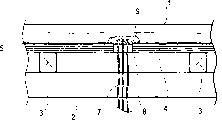
Figure 1A is a schematic diagram of showing the roof of an example of the present invention;
Figure 1B is the part section diagrammatic sketch of getting along the line 1B-1B among Figure 1A;
Fig. 1 C is the part section diagrammatic sketch of getting along the line 1C-1C among Figure 1A;
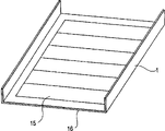
Fig. 2 is a perspective illustration of showing the example of the solar module that is used for roof structure of the present invention;
Fig. 3 is a section diagrammatic sketch of showing the solar energy house roof construction of an example of the present invention;
Fig. 4 A is the section diagrammatic sketch of introducing opening of the solar cell roof structure of example 1;
Fig. 4 B is the perspective pictorial view of introducing opening of the solar cell roof structure of example 1;
Fig. 5 is the perspective pictorial view of example of showing the routine fire prevention construction method of the penetrated section be used for fire compartment;
Fig. 6 A is the perspective pictorial view of showing an example of fireproof performance test;
Fig. 6 B is the peripheral section diagrammatic sketch of combustion charcoal part of fireproof performance test;
Fig. 7 A and 7B are the perspective pictorial view that is used for the solar module of example 3;
Fig. 8 A is the section diagrammatic sketch of the solar cell roof structure of example 2;
Fig. 8 B is the section diagrammatic sketch of sealing device of the solar cell roof structure of example 2;
Fig. 8 C is the perspective pictorial view of sealing device of showing the solar cell roof structure of example 2;
Fig. 9 is the perspective pictorial view of showing the solar module that is used for example 3;
Figure 10 A is the perspective pictorial view of inside of showing the solar cell roof structure of example 3;
Figure 10 B is the section diagrammatic sketch that the line 10B-10B along Figure 10 A gets, and is used to show the solar cell roof structure of example 3;
Figure 10 C is the section diagrammatic sketch that the line 10C-10C along Figure 10 A gets, and is used to show the introducing opening of the solar cell roof structure of example 3;
Figure 11 A and 11B are the section diagrammatic sketch of introducing opening of showing another solar cell roof structure of example 3;
Figure 12 is the schematic configuration diagram of the photoelectricity electric energy generating system that is applied thereon of the present invention;
Figure 13 A is the section diagrammatic sketch of the sealing device of example 4;
Figure 13 B and 13C are the section diagrammatic sketch of another sealing device of example 4;
Figure 13 D is the partial plan layout corresponding to Figure 13 B.
The specific embodiment
According to the structure of the invention described above, can improve water resistance.In addition, go into by orifice flow all, reduce to the oxygen supply in space between solar module and roof substrate, can improve the fireproof performance on roof by preventing fresh air.When adopting heat proof material or refractory material to make seal member, this performance becomes more remarkable.Even if fire makes solar module distortion, can prevent that also the charcoal that burning from contacting with electrical lead in the through hole top.In outlet from the seal member of electrical lead to space solar module and roof substrate, be arranged at when directly over the through hole of seal member or directly exceptionally seal member is partly gone up at an upper portion thereof, this performance becomes more remarkable.If adopt this structure, electrical lead be arranged in parallel easily, or almost be arranged in parallel with the roof substrate.So the distance between solar module and roof substrate can shorten, suppose because moving around outlet of lead-in wire forms to have the advantage that the gap can not reach through hole.
Among the present invention, seal member (after this being sometimes referred to as " substrate seal member ") preferably includes a plurality of seal members.In a plurality of seal members, at least two can comprise same material.For example, comprise a plurality of parts combinations of same material, and, can improve the degree of freedom of operation as seal member.Nature also can adopt different materials.
In addition, solar module better is almost to contact with the roof basal surface with electrical lead between through hole.According to this structure, the space between solar module and roof substrate is done narrowlyer.When arranging electrical lead, except that with part that solar module is connected part in, do not contact with the back side of assembly, even if solar module is heated, better be heat also difficulty be transmitted to electrical lead.
The preferred embodiment that constitutes the seal member with a plurality of seal members is: (1) seal member has first seal member and second seal member at least, second seal member surrounds electrical lead around the suprabasil through hole on the roof, to cover through hole and neighbouring part thereof, (2) seal member comprises at least and is fixed in first seal member of ventilation of through hole peripheral edge portion with the restriction through hole, second seal member covers through hole, (3) seal member have not flammable second seal member that covers through hole at least and be arranged at second seal member and the roof substrate between anti-flaming first seal member in the space, (4) seal member comprises second seal member that covers through hole at least, be arranged on around the through hole and first seal member on the roof base side of electrical lead, and be arranged on around the through hole and the 3rd seal member on the solar module side of electrical lead (the preferred first and the 3rd seal member forms one).
In the structure of above-mentioned (2), first seal member is installed on the peripheral edge portion, can prevent that electrical lead from contacting with peripheral edge portion, thus, can prevent the electrical lead damage that causes with the peripheral edge portion friction.If the part between the periphery of through hole and electrical lead is the part of seal member, then can also contact and realize this effect by the periphery that makes through hole with electrical lead.Better be that the seal member between through hole periphery and electrical lead (or part of seal member) is made of the material softer than periphery.For example, can make seal member with putty, clay, organic polymer material.
In addition, the seal member that the present invention adopts better is deformable, if adopt deformable seal member, then seal member distortion to adapt to the setting of electrical lead in the processing, makes it easy.In addition, about seal member, can adopt a kind of passing by in time and solidify the material of (sclerosis or solidify).Make stability after encapsulant can be realized easily operation and processing simultaneously with curing materials.This material exemplary has putty, clay etc.
A part that better is seal member at least comprises heat proof material or refractory material.Be more preferably heat proof material or refractory material filling vias are set.Be well that whole seal member comprises heat proof material or refractory material again.Refractory material is more preferably and can compares favourably with heat proof material.If make heat proof material with the anti-very material of high temperature, then be equivalent to refractory material.
The a part of right and wrong that better are seal member at least are infiltrative, and the part that is more preferably impermeability covers through hole.About this seal member, better be to adopt parts with impervious bed.Be more preferably whole seal member and all do not have permeability.
Better be that the roof substrate has the inclined-plane, tilt, and on the inclined-plane downward direction, with respect to the outlet of through hole setting from the seal member of electrical lead to space solar module and roof substrate.Utilize this structure, reduce by the possibility that through hole invades roof backside of substrate flowing water along electrical lead.
Better be the circular arc (circle) on electrical lead is arranged to from the through hole to the through hole.Utilize this structure, can be easily and be parallel to or almost be parallel to the roof basal surface naturally electrical lead is set.
Better be that solar module that the present invention adopts is and has an integrated solar module of roof Material of the bracing or strutting arrangement that combustible material (metal sheet) not constitutes.Utilize this structure, the deformation of solar cell can be restricted to minimum, can strengthen effect of the present invention.When adopting this structure, the combustion charcoal that sees through bracing or strutting arrangement can not descend.Therefore, better be the whole back side or the almost whole back side that the bracing or strutting arrangement of not combustible material is arranged at solar module.
Introduce the preferred embodiments of the present invention below in conjunction with accompanying drawing.
Figure 1A-1C is the diagrammatic sketch that the solar module 1 according to structure of the present invention is applied to do on the roof embodiment of roofing materials.Figure 1A is the configuration diagram on roof.Figure 1B is the 1B-1B sectional drawing (part) of Figure 1A, and Fig. 1 C is the 1C-1C sectional drawing (part) of Figure 1A.Fig. 2 is the perspective pictorial view of showing the embodiment that is used for solar module of the present invention.As shown in Figure 2, the junction box 13 of transmission electric energy has been fixed in the back side of solar module.Electrical lead parts 7 have been connected to junction box 13.Shown in Figure 1B, rafter 3 is fixed on the stringer 2 of building.On stringer 2, place the roof coating plate, form the roof basal surface.Generally speaking, it is provided with waterproof bed material 5.The fixed part 6 that is called clip is roofing materials 1 fixedly.The roof substrate has lead member 7 connected to one another and the roof lead-in wire 7a that is used for being connected from the outside lead-in wire with 1 of roofing materials.On the roof basal surface, building wall body outside has as draw the through hole of lead member as ejector 8 from the outside.Lead member 7 is passed through hole 8, is connected to the lead-in wire 7a on roof.On through hole 8, sealing device (seal member) 9 is set.
(solar module 1)
As shown in Figure 2, the preferred example of the solar module 1 that adopts of the present invention has solar cell 15 to be fixed in solar module on the bracing or strutting arrangement 16.Can make bracing or strutting arrangement 16 with glass plate and film, be used for the support of solar cell 15 light receiving surface sides, can adopt steel plate to make the bracing or strutting arrangement 16 shown in Fig. 2, be used for the support of solar cell 15 non-light receiving surface sides.In order to increase intensity, for example have frameworks such as aluminium frame around the bracing or strutting arrangement 16 in the parts.Be used for roofing materials 1 of the present invention and be installed to aforesaid roof coating plate 4, in addition, can be installed on the conventional roofing materials and have on the roofing materials of roof effect.In addition, to the solar cell 15 that is used for roofing materials 1 of the present invention without limits, for example, can be with the solar cell, monocrystaline silicon solar cell, polysilicon solar cell, microcrystalline silicon solar cell, the non-crystal silicon solar cell that utilize silicon semiconductor to make, can also be with the solar cell, III-V compounds of group solar cell, II-VI compounds of group solar cell, the I-III-VI compounds of group solar cell that utilize chemical compound semiconductor to make.In addition, the solar cell that can make with semi-conductive combination.
Being used for solar cell of the present invention better is non-crystal silicon solar cell.Non-crystal silicon solar cell can be prepared on the film substrate and the film of conductive substrate, so alleviated the weight of solar cell self.In addition, compare with solar cells made of crystalline silicon, non-crystal silicon solar cell at high temperature also has good output characteristics, is suitable for most producing on the roof of high temperature.In addition, its substrate is to utilize the non-crystal silicon solar energy electricity of conductive substrate preparation to have higher structural strength and pliability, even if upwards arc or protruding arranged, still has degree of freedom in the shape direction with when being installed on the deck.
In addition; utilize non-glass solar battery surface protective material; rather than weather film; when being used for metal roof; make back side reinforcement material with metal foil; can be crooked as metal roof, form for example folded sheet shape, buckle stitching shape and horizontal roofing shape, and the waterproof action of roofing materials is provided.This better is to make the installation cost of new building and improvement building lower.In addition, the back side reinforcement material that metal sheet constitutes can cut off flame from the outside, so and make that deformability is lower to have a fireproof performance.
(roof coating plate 4)
(waterproof bed material 5)
When roofing materials 1 was covered on the upper surface of roof coating plate 4, waterproof bed material 5 can be used for improving the water resistance on roof.If utilize roofing materials 1 and inclined-plane, roof can realize good water resistance, then do not need waterproof bed material 5.Yet generally speaking, bed material is as secondary waterproof means.About waterproof bed material 5, pitch roof coating commonly used and asphalt felt.Yet, without limits to these materials.
(lead member 7)
Specifically, here the preferred lead-in wire that adopts comprises the 600V polyethylene insulated cable (EV of JIS C3605 standard, EE, CV, CE), 600V level ethylene-propylene (EP) India-rubber cable (PN of JIS C3621 standard, PV), the 600V grade PVC insulation shielding (circle of JIS C3342 standard, platypelloid type) cable (VVR, VVF), 1 grade of JIS C3327 standard, 2 grades, 3 grades, or 4 grades of 600V cabtyre cables (1CT, 2CT, 3CT, 4CT), 2 grades of JIS C3327 standard, 3 grades, or 4 grades of rubber covered chlorobutadiene flexible cables of 600V (2RNCT, 3RNCT, 4RNCT), 2 grades of JIS C3327 standard, 3 grades, or the rubber covered chlorobutadiene flexible cable of 4 grades of 600V ethylene-propylenes (EP) (2PNCT, 3PNCT, 4PNCT), or the soft insulated cable of ethene of the 600V grade PVC insulation shielding of JIS C3312 standard.
In the present embodiment, electrical lead has with respect to the position directly over the through hole by the outlet in its following seal member that extends on the roof basal surface and departs from.
(through hole 8)
Through hole 8 provides and is used for lead member is guided to the hole of the dorsal part of roof coating plate, roofing etc.
(sealing device (seal member) 9)
As shown in Figure 2, installation is used for sealing device of the present invention (seal member) 9, to cover the through hole 8 as the lead-in wire ejector, prevents that air from flowing into from through hole 9, and considers solar module as roofing materials, covers lead material 7.About seal member 9, better be to adopt to be exposed to incombustible anti-heat seal mateiral and for example various nonflammable parts such as metal sheet, asbestos, glass fiber in the high temperature.The temperature resistant encapsulation part has freedom shape, can be filled in the space between cable material, forms the better seal device.In addition, for water resistance is provided, can on the surface of heat-resistant seal material, apply anti-flaming surperficial face protective material.In addition, use metal-plate-covered cap surface, and utilize heat-resistant seal material in the space between cable, become the embodiment of the sealing device that combines with these parts.Having more low-melting metal sheet with for example aluminium etc. when making metal sheet,, should take into full account its thickness from the anti-deformation angle.
The distance between installation aiding device according to solar module and lead-in wire can adopt silicon rubber for example etc. to have the parts and the flame resistant material of heat resistance.About this parts, better be the material of anti-air-flow ability excellence.
About having the parts of heat resistance and anti-flaming performance, obtain commercially available heat-resisting putty easily, so better adopt this material.
About having the parts of heat resistance and anti-flaming performance, the parts that comprise known different materials are used in selection that can be suitable.For example, can independently use or use the fluorinated polyimide material as mixture, the carbon back refractory material, for example silica, zircon, alumina, spinelle, magnesia, dolomite, calcium oxide, calcium carbonate, glass fiber, carborundum, silicon nitride, graphitic carbon etc., has high-melting point metal, for example graphite, tungsten and molybdenum etc.
[example]
Below in conjunction with case introduction the present invention.Following example all is exemplary, and nonrestrictive.
(example 1)
In this example, as shown in Figure 2, solar module 1 is made of the non-crystal silicon solar cell 15 of series connection, and its back side has by the resin-sealed galvanized steel strap 16 of weather.Solar module 1 is bent, and makes horizontal roof coating shape, and a plurality of solar modules connect the roof coating plate.Be described in detail below.
In order to constitute the roof of building, as shown in Figure 3, post plate 19, stringer 2 and rafter 3 are set, and the veneer that the 12mm be used for structure is installed is as the roof coating plate 4 on it so that with the drill bit screw to rafter 3.On the surface of roof coating plate 4,, the pitch roof coating as waterproof bed material 5 is installed, on the roof coating plate 4 that nails in order to ensure water resistance.Leave through hole (diameter 90mm) 8 as connecton layout.At first, pass the top of this through hole 8 from the bottom of this roof coating plate 4, and be arranged on the position that position that the positive electrode of the solar module group of series connection exposes and negative electrode expose to roofing coating plate 4 as the CV cable 7 of wiring part.Around through hole 8, CV cable 7 is set, make it to contact with the surface of pitch roof coating 5.Apply heat proof material 9 (NITTO KASEI CO., LTD makes, trade name P1aseal NF-5DS) thereon, to have the position covering cable 7 of counting the radius of 60mm from the through hole center.
Then, connection will transmit the stube cable and the solar module that is one another in series of the output of solar cell, and fix with the fixed part that is called anchor clamps 6, as shown in Figure 2.
After utilizing this technology to cover the roof, the CV cable of extension is connected to the junction box that is installed on the building inwall.
According to this example, be electrically connected easily, can shorten wiring, thereby can reduce the electric energy loss that causes because of the cloth line resistance, and can improve reliability.
As shown in Figure 5, the conventional water-proofing method that is used for the penetrated section of fire compartment in basis, in through hole 8 cable 7 around, utilize in the method for heat-resistant seal material 9, heat-resistant seal material 9 is fixing unsatisfactorily, and can not realize gratifying fireproof performance, when the roof coating plate of making at roof substrate 4 and the veneer that is used for structure approaches equally, the space that roof coating plate 4 and roofing materials are 1 is narrow, adopts the cable 7 that has sweep in the through hole 8.
According to said method of the present invention, shown in Fig. 6 A and 6B, make the simulation roof, on the roofing materials 1 on through hole 8 tops, the combustion charcoal 18 that is made of 550 gram Douglas fir wood is set, and when burning, blows the wind of 3 meter per seconds, carry out roof fire prevention test.After the test, observe the roof coating plate and almost do not change, obtained excellent flameproof effect.Can think this result be almost completely prevent from through hole 8 leaked-in air and by the position of concentrating at cable 7 for example through hole 8 provide the basis of the heat-absorbing action of heat-resistant seal material 9 to obtain, can prevent that the roof coating plate around the through hole 8 is heated.This test is actual to have proved effect of the present invention.
(example 2)
The solar module that replacement is made with the non-crystal silicon solar cell of example 1, in this example, the sealed solar energy battery component that preparation utilizes crystalline solar cells to make, and utilize the fixedly installed part of aluminium frame, the aluminium frame of installation component on the roof coating plate.
Describe in detail below in conjunction with Fig. 7 A and 7B.Solar cell 15 is the solar cells made of crystalline silicon with grid, 15 solar cells made of crystalline silicon of connecting, respectively in that (fixing glass 24 and aluminium foil on the surface that Tedlar (DuPont manufacturing)/aluminium foil/Tedlar) constitutes and the back side are made back side film 25 and are sealed with EVA26 by the moisture-proof fluororesin.Then, adhere to aluminium frame 27 as reinforcement material on four limits, and use adhesive, make the solar cells made of crystalline silicon assembly.
By utilizing the gummed shaving board to make roof coating plate 4, make the roof bed material with pitch roof coating 29, install and fix parts 30, the aluminium frame of solar module is fixed thereon fixed solar battery pack shown in Fig. 8 A.The output lead of solar module and the grounding wire that is connected to the aluminium frame are installed to the inside of building by the erecting device on the roof surface (through hole 8).
In erecting device, shown in Fig. 8 B and 8C, processing galvanized steel plain sheet 31, fixing heat-resistant material on that part of galvanized steel plain sheet that cable passes (by NITTO KASEI CO., LTD. makes, and commodity are called PlasealNF-5DS) 9, and, cable 7 is installed by compressing into this part from the bottom of through hole.
According to present embodiment, carry out this electrical connection easily, can reduce length of arrangement wire, thereby reduce the cloth line resistance, so the electric energy that can effectively utilize solar cell to produce.
Test according to the roof fire prevention that present embodiment carries out shown in example 1, obtained excellent similarly to Example 1 fireproof performance.This may be because by almost completely having prevented to have prevented the fresh air supply from through hole 8 leaked-in airs, thereby has limited the cause of burning.
(example 3)
In this example, by the solar module that bending process has the layer structure that is similar to example 1, make buckle stitching roof shape and make roofing materials 1, as shown in Figure 9, a plurality of this roofing materialss are connected to roof coating plate 4, following mask body introduction.
In order to constitute the gable top in the building as shown in figure 10, post plate, stringer and rafter 3 are set, it is provided with the gummed shaving board and makes roof coating plate 4, so that with drill bit screw rafter 3.In order to ensure water resistance, on the surface of roof coating plate 4, nail as the pitch roof coating of bed material 5.In vertical direction, with half spacing of about roofing materials 1 width, fixed frame strip 17 thereon.The part that the junction box of solar module and moulding 17 have a common boundary is made concave shape.In addition, on roof coating plate 4, open also through hole 8 as erecting device.Then, at first CV cable 7 promptly extends wiring part and passes this through hole 8 from the bottom of roof coating plate 4 to its top, and is laid in the position that position that the positive electrode of the solar module group of series connection exposes and negative electrode expose.Under the cable of installing, fixing bar shaped first heat-resistant seal material as first sealing device (NITTO KASEI CO., LTD makes, trade name PlasealNF-5DS) 35 is so that be installed on through hole 8 bed material 5 on every side.On first sealing device, installation is as second heat-resistant seal material 34 of second sealing device, with the 3rd heat-resistant seal material 36 (these two kinds of encapsulants are identical with first encapsulant) of making the 3rd sealing device, thereby has the position covering cable 7 of counting the radius of 80mm from through hole 8 centers.
After this step, connect the stube cable of the output that will transmit solar module, and fix, shown in Figure 10 B with the fixed part that is called anchor clamps 6 in the mode that is one another in series.Part between each roofing materials is installed buckle cap 23.
After covering the roof by this way, the CV cable of extension is connected to the junction box that is installed on the building inwall.
According to this example, be electrically connected easily, can shorten length of arrangement wire, improve reliability.
When the through hole of (ridge side) is installed cable from the higher position, because first heat-resistant seal material 35 is installed under the cable, so can prevent that sealing infiltrates interior of building along cable.In addition, fireproof performance with
Embodiment 1 is identical.
In this example, heat-resistant seal material 35 is installed under the cable.As shown in figure 11, when around through hole 8, all being coated with second heat-resistant seal material 34, do sealing device 35 and 36 with different vegetable corks, replace the first and the 3rd heat-resistant seal material with insulation materials such as resin for example and rubber.
(example 4)
This example has the Installation Modes identical with example 3, is different from throughhole portions 8.Introduce in detail below.
On roof coating plate 4, leave through hole 8 parts as erecting device.Shown in Figure 13 A-13D, adhere to first heat-resistant seal material (NITTOKASEI CO. at the periphery of throughhole portions 8 as first sealing device, LTD makes, trade name Plaseal NF-5DS) 35, at first the CV cable 7 of Yan Shening passes the top of this through hole 8 to the roof coating plate from the bottom of roof coating plate 4, and is laid in the position that position that the positive electrode of the solar module group of series connection exposes and negative electrode expose.Second heat-resistant seal material (quality is identical with first heat-resistant seal material) 34 as second sealing device is installed thereon, thereby is had the position covering cable 7 of counting the radius of 60mm from the through hole center.
Then, in the mode that is one another in series, connect solar module and will transmit the stube cable of the output of solar cell, and fix with the fixed part that is called anchor clamps 6.As shown in Figure 2.Part between each roofing materials is installed the buckle cap.
After covering the roof by this way, the CV cable of extension is connected to the junction box that is installed on the building inwall.
According to this example, be electrically connected easily, can shorten length of arrangement wire, improve reliability.
When the through hole of (ridge side) is installed cable 7 from the higher position,,, can prevent that also sealing infiltrates interior of building along cable even if second sealing device 34 can not be realized water resistance owing to be installed under the cable 7 as the heat-resistant seal material 35 of first sealing device.In addition, fireproof performance is identical with embodiment 1.
In this example, adopt heat-resistant seal material to make second sealing device.Yet waterproof and sealing material all has same effect with the circular hole lid that is used for the electric channel system shown in Figure 13 B and the 13C.When using flame-proof sealing material, its heat resisting temperature can hang down slightly, and its quality can be a resin, yet, better be incombustible material or the material except that anti-flaming property such as metal for example with fireproof performance.
As mentioned above, solar cell roof structure of the present invention and constructive method thereof have following effect.
(1) by being used for the through hole that cable introduces sealing device is provided being arranged in the roof substrate, improved Water resistance.
(2) empty with narrow place as between solar module and roof coating plate, the present invention can be used for Improve the fire protecting performance such as the concentrated place of the connecton layouts such as cable that comprises organic material, easily operation, And can improve the design freedom of solar module self.
(3) introducing method by improving wiring part and the sealing device under the wiring part can be further Improve water resistance.
Claims (132)
1. solar cell roof structure comprises:: the suprabasil solar module in building roof; Be arranged on the electrical lead of the solar module in the space between solar module and the roof substrate, this electrical lead is by being arranged on the space that through hole in layer top substrate extends to the roof backside of substrate, this solar cell roof structure also comprises the substrate seal member that is used to cover through hole in the roof substrate, wherein, the part of described substrate seal member beyond directly over its through hole provides outlet, and electrical lead extends to above-mentioned space between solar module and the roof substrate by this outlet.
2. according to the solar cell roof structure of claim 1, wherein, described substrate seal member comprises a plurality of seal members.
3. according to the solar cell roof structure of claim 2, wherein, in described a plurality of seal members at least two are made of identical materials.
4. according to the solar cell roof structure of claim 1, wherein, the electrical lead between described solar module and the through hole contacts with the roof substrate substantially.
5. according to the solar cell roof structure of claim 1, wherein, described substrate seal member comprises first and second seal members at least, wherein, second seal member periphery of through hole on substrate parts surrounds described electrical lead, and covers through hole and its periphery.
6. according to the solar cell roof structure of claim 1, wherein, thereby described substrate seal member comprises that at least being arranged on the through hole peripheral edge portion suppresses first seal member that ventilates by through hole and second seal member that covers the upside of through hole.
7. according to the solar cell roof structure of claim 1, wherein, described substrate seal member comprise non-flammable second seal member that covers the through hole upside at least and be arranged on second seal member and the roof substrate between the gap in the first fire-retardant seal member.
8. according to the solar cell roof structure of claim 1, wherein, first seal member of the periphery of the through hole of the roof base side that described substrate seal member comprises second seal member that covers the through hole upside at least, be arranged at electrical lead and be arranged at the 3rd seal member of through hole periphery of the solar module side of electrical lead.
9. solar cell roof structure according to Claim 8, wherein, the described first and the 3rd seal member forms one.
10. according to the solar cell roof structure of claim 1, wherein, at least a portion of described substrate seal member is made of heat-resisting or refractory material.
11. according to the solar cell roof structure of claim 1, wherein, described substrate seal member is made of heat-resisting or refractory material.
12. according to the solar cell roof structure of claim 1, wherein, at least a portion of described substrate seal member has impermeability.
13. according to the solar cell roof structure of claim 12, wherein, described substrate seal member comprises impervious bed.
14. solar cell roof structure according to claim 1, wherein, the substrate of described roof is tilted, and the outlet in the wherein said substrate seal member is arranged on respect to through hole along on the downward direction in inclined-plane, and described electrical lead extends in the space between solar module and the roof substrate by this outlet.
15. according to the solar cell roof structure of claim 1, wherein, described electrical lead is arranged to circle in through hole He on the through hole.
16. according to the solar cell roof structure of claim 1, wherein, described solar module is and roof Material all-in-one-piece solar module, it comprises the bracing or strutting arrangement that is made of combustible material not.
17. a method that constitutes the solar cell roof, this solar cell roof comprises the suprabasil solar module in building roof; Be arranged on the electrical lead of the solar module in the space between solar module and the roof substrate, this electrical lead is by being arranged on the space that through hole in the roof substrate extends to the roof backside of substrate, and this method comprises:
The substrate seal member is provided in the roof substrate, is used to cover through hole; And
Part beyond directly over the through hole of described substrate seal member provides outlet, and described electrical lead extends in the space between solar module and the roof substrate by this outlet.
18. the method according to claim 17 comprises: utilize a plurality of seal members to make the substrate seal member.
19. according to the method for claim 18, wherein, in a plurality of seal members at least two are made of identical materials.
20. the method according to claim 17 comprises: basic and roof substrate is provided with electrical lead contiguously in the space between solar module and roof substrate.
21. the method according to claim 17 comprises:
At least utilize first and second seal members as the substrate seal member, and
Provide second seal member so that the periphery of through hole surrounds electrical lead on substrate parts, and cover through hole and its periphery.
22. the method according to claim 17 comprises: thus suppress first seal member that ventilates by through hole and cover second seal member of through hole upside with being arranged on described through hole peripheral edge portion at least as the substrate seal member.
23. the method according to claim 17 comprises: at least with cover non-flammable second seal member of through hole upside and be arranged on second seal member and the roof substrate between the gap in the first fire-retardant seal member as the substrate seal member.
24. method according to claim 17, comprise: at least with second seal member that covers the through hole upside, first seal member of periphery of through hole of roof base side that is arranged at electrical lead and the 3rd seal member of periphery of through hole of solar module side that is arranged at electrical lead as the substrate seal member.
25. according to the method for claim 24, wherein, the described first and the 3rd seal member forms one.
26. according to the method for claim 17, wherein, at least a portion of described substrate seal member is made of heat-resisting or refractory material.
27. according to the method for claim 17, wherein, described substrate seal member is made of heat-resisting or refractory material.
28. according to the method for claim 17, wherein, at least a portion of described substrate seal member has impermeability.
29. according to the method for claim 28, wherein, described substrate seal member comprises impervious bed.
30. according to the method for claim 17, wherein, the substrate of described roof is tilted, wherein, on the direction downward along the inclined-plane, with respect to through hole the outlet of described base seal is set, electrical lead extends in the space between solar module and the roof substrate by this outlet.
31. the method according to claim 17 comprises: in through hole He on the through hole, electrical lead is arranged to circle.
32. according to the method for claim 17, wherein, described solar module is and roof Material all-in-one-piece solar module, it comprises the bracing or strutting arrangement that is made of combustible material not.
33. a photoelectricity electric energy generation device comprises:: the suprabasil solar module in building roof; Be arranged on the electrical lead of the solar module in the space between solar module and the roof substrate, this electrical lead is by being arranged on the space that through hole in the roof substrate extends to the roof backside of substrate, this photoelectricity electric energy generation device also comprises the substrate seal member that is used to cover through hole in the roof substrate, wherein, the part of described substrate seal member beyond directly over its through hole provides outlet, and electrical lead extends in the space between solar module and the roof substrate by this outlet.
34. according to the device that claim 33 photoelectricity electric energy takes place, wherein, described substrate seal member comprises a plurality of seal members.
35. according to the photoelectricity device for generating electric energy of claim 34, wherein, in described a plurality of seal members at least two are made of identical materials.
36. according to the photoelectricity device for generating electric energy of claim 33, wherein, the electrical lead between described solar module and the through hole contacts with the roof substrate substantially.
37. photoelectricity device for generating electric energy according to claim 33, wherein, described substrate seal member comprises first and second seal members at least, wherein, the periphery of second seal member through hole on substrate parts surrounds electrical lead, and covers through hole and its periphery.
38. the photoelectricity electric energy according to claim 33 is decided generating apparatus, wherein, thereby described substrate seal member comprises that at least being arranged on the through hole peripheral edge portion suppresses first seal member that ventilates by through hole and second seal member that covers the upside of through hole.
39. photoelectricity device for generating electric energy according to claim 33, wherein, described substrate seal member comprise non-flammable second seal member that covers the through hole upside at least and be arranged on second seal member and the roof substrate between the gap in the first fire-retardant seal member.
40. photoelectricity device for generating electric energy according to claim 33, wherein, described substrate seal member comprise second seal member that covers the through hole upside at least, first seal member of the periphery of the through hole of the roof base side that is arranged at electrical lead and be arranged at the 3rd seal member of through hole periphery of the solar module side of electrical lead.
41. according to the photoelectricity device for generating electric energy of claim 40, wherein, the described first and the 3rd seal member forms one.
42. according to the photoelectricity device for generating electric energy of claim 33, wherein, at least a portion of described substrate seal member is made of heat-resisting or refractory material.
43. according to the photoelectricity device for generating electric energy of claim 33, wherein, described substrate seal member is made of heat-resisting or refractory material.
44. according to the photoelectricity device for generating electric energy of claim 33, wherein, at least a portion of described substrate seal member has impermeability.
45. according to the photoelectricity device for generating electric energy of claim 44, wherein, described substrate seal member comprises impervious bed.
46. photoelectricity device for generating electric energy according to claim 33, wherein, the substrate of described roof is tilted, and wherein with respect to through hole outlet in the described substrate seal member is set on the direction downward along the inclined-plane, described electrical lead extends in the space between solar module and the roof substrate by this outlet.
47. according to the photoelectricity device for generating electric energy of claim 33, wherein, described electrical lead is arranged to circle in through hole He on the through hole.
48. according to the photoelectricity device for generating electric energy of claim 33, wherein, described solar module is with the roof Material all-in-one-piece, comprises the solar module of the bracing or strutting arrangement that is made of combustible material not.
49. a building comprises:: the suprabasil solar module in building roof; Be arranged on the electrical lead of the solar module in the space between solar module and the roof substrate, this electrical lead is by being arranged on the space that through hole in the roof substrate extends to the roof backside of substrate, this building also comprises the substrate seal member that is used to cover through hole in the roof substrate, wherein, the part of described substrate seal member beyond directly over its through hole provides outlet, and described electrical lead extends in the space between solar module and the roof substrate by this outlet.
50. according to the building of claim 49, wherein, described substrate seal member comprises a plurality of seal members.
51. according to the building of claim 50, wherein, in described a plurality of seal members at least two are made of identical materials.
52. according to the building of claim 49, wherein, the electrical lead between described solar module and the roof substrate contacts with the roof substrate substantially.
53. according to the building of claim 49, wherein, described substrate seal member comprises first and second seal members at least, wherein, the periphery of second seal member through hole on substrate parts surrounds electrical lead, and covers through hole and its periphery.
54. according to the building of claim 49, wherein, described substrate seal member comprises at least and is arranged on the through hole peripheral edge portion to suppress first seal member that ventilates by through hole and to cover second seal member of the upside of through hole.
55. according to the building of claim 49, wherein, the substrate seal member comprise non-flammable second seal member that covers the through hole upside at least and be arranged on second seal member and the roof substrate between the gap in the first fire-retardant seal member.
56. building according to claim 49, wherein, first seal member of the periphery of the through hole of the roof base side that described substrate seal member comprises second seal member that covers the through hole upside at least, be arranged at electrical lead and be arranged at the 3rd seal member of through hole periphery of the solar module side of electrical lead.
57. according to the building of claim 56, wherein, the described first and the 3rd seal member forms one.
58. according to the building of claim 49, wherein, at least a portion of described substrate seal member is made of heat-resisting or refractory material.
59. according to the building of claim 49, wherein, described substrate seal member is made of heat-resisting or refractory material.
60. according to the building of claim 49, wherein, at least a portion of described substrate seal member has impermeability.
61. according to the building of claim 60, wherein, described substrate seal member comprises impervious bed.
62. building according to claim 49, wherein, the substrate of described roof is tilted, and the outlet in the wherein said substrate seal member is arranged on along on the downward direction in inclined-plane with respect to through hole, and described electrical lead extends in the space between solar module and the roof substrate by this outlet.
63. according to the building of claim 49, wherein, described electrical lead is arranged to circle in through hole He on the through hole.
64. according to the building of claim 49, wherein, described solar module is and roof Material all-in-one-piece solar module, it comprises the bracing or strutting arrangement that is made of combustible material not.
65. a solar cell roof structure comprises:: the suprabasil solar module in building roof; Be arranged on the electrical lead of the solar module in the space between solar module and the roof substrate, this electrical lead extends in the space of roof backside of substrate by the through hole that is arranged in the roof substrate, wherein, the substrate seal member that comprises heat-resisting or refractory material is provided in the roof substrate, is used to cover through hole.
66. according to the solar cell roof structure of claim 65, wherein, described substrate seal member comprises a plurality of seal members.
67. according to claim 66 solar cell roof structure, wherein, at least two in described a plurality of seal members comprise identical materials.
68. according to the solar cell roof structure of claim 65, wherein, the electrical lead that is provided in the space between described solar module and the roof substrate contacts with the roof substrate substantially.
69. solar cell roof structure according to claim 65, wherein, described substrate seal member comprises first and second seal members at least, and the through hole periphery of described second seal member wherein on substrate parts surrounds electrical lead, and covers described through hole and its periphery.
70. according to the solar cell roof structure of claim 65, wherein, thereby described substrate seal member comprises that at least being arranged on the through hole peripheral edge portion suppresses first seal member that ventilates by through hole and second seal member that covers the upside of through hole.
71. solar cell roof structure according to claim 65, wherein, described substrate seal member comprise non-flammable second seal member that covers the through hole upside at least and be arranged on second seal member and the roof substrate between the gap in the first fire-retardant seal member.
72. solar cell roof structure according to claim 65, wherein, first seal member of the periphery of the through hole of roof substrate one side that described substrate seal member comprises second seal member that covers the through hole upside at least, be arranged at electrical lead and be arranged on the 3rd seal member of through hole periphery of solar module one side of electrical lead.
73. according to the solar cell roof structure of claim 72, wherein, the described first and the 3rd seal member forms one.
74. according to the solar cell roof structure of claim 65, wherein, at least a portion of described substrate seal member has impermeability.
75. according to the solar cell roof structure of claim 74, wherein, described substrate seal member comprises impervious bed.
76. solar cell roof structure according to claim 65, wherein, the substrate of described roof is tilted, and the outlet in the wherein said substrate seal member is arranged on along on the downward direction in inclined-plane with respect to through hole, and electrical lead extends in the space between solar module and the roof substrate by this outlet.
77. according to the solar cell roof structure of claim 65, wherein, described electrical lead is arranged to circle in through hole He on the through hole.
78. according to the solar cell roof structure of claim 65, wherein, described solar module is and roof Material all-in-one-piece solar module, it comprises the bracing or strutting arrangement that is made of combustible material not.
79. a method that constitutes the solar cell roof structure, this solar cell roof comprises the suprabasil solar module in building roof; Be arranged on the electrical lead of the solar module in the space between solar module and the roof substrate, this electrical lead is introduced in the space of roof backside of substrate by the through hole that is arranged in the roof substrate, this method comprises: provide in the roof substrate by substrate seal member heat-resisting or that refractory material constitutes, be used to cover through hole.
80., comprise with a plurality of seal members and make the substrate seal member according to the method for claim 79.
81. 0 method according to Claim 8, wherein, in described a plurality of seal members at least two are made of identical materials.
82. the method according to claim 79 comprises: basic and roof substrate is provided with electrical lead contiguously in the space between solar module and roof substrate.
83. the method according to claim 79 comprises: use first and second seal members as the substrate seal member at least, and provide second seal member, and cover through hole and its periphery so that the periphery of the through hole on substrate parts surrounds electrical lead.
84. the method according to claim 79 comprises: at least be arranged on the through hole peripheral edge portion with second seal member of upside that suppresses first seal member that ventilates by through hole and cover through hole as the substrate seal member.
85. the method according to claim 79 comprises: at least with cover non-flammable second seal member of through hole upside and be arranged on second seal member and the roof substrate between the gap in the first fire-retardant seal member as the substrate seal member.
86. method according to claim 79, wherein, at least with second seal member that covers the through hole upside, first seal member of periphery of through hole of roof base side that is arranged at electrical lead and the 3rd seal member of through hole periphery of solar module side that is arranged at electrical lead as the substrate seal member.
87. 6 method according to Claim 8, wherein, the described first and the 3rd seal member forms one.
88. according to the method for claim 79, wherein, at least a portion of described substrate seal member has impermeability.
89. 8 method according to Claim 8, wherein, described substrate seal member comprises impervious bed.
90. method according to claim 79, wherein, the substrate of described roof is tilted, and the outlet in the wherein said substrate seal member is arranged on along on the downward direction in inclined-plane with respect to through hole, and described electrical lead extends in the space between solar module and the roof substrate by this outlet.
91. the method according to claim 79 comprises: in through hole He on the through hole, electrical lead is arranged to circle.
92. according to the method for claim 79, wherein, described solar module is and roof Material all-in-one-piece solar module, it comprises the bracing or strutting arrangement that is made of combustible material not.
93. a photoelectricity device for generating electric energy comprises:: the suprabasil solar module in building roof; Be arranged on the electrical lead of the solar module in the space between solar module and the roof substrate, this electrical lead extends in the space of roof backside of substrate by the through hole that is arranged in the roof substrate, wherein, the substrate seal member that comprises heat-resisting or refractory material is provided in the roof substrate, is used to cover through hole.
94. according to the photoelectricity device for generating electric energy of claim 93, wherein, described substrate seal member comprises a plurality of seal members.
95. according to the photoelectricity device for generating electric energy of claim 94, wherein, in described a plurality of seal members at least two are made of identical materials.
96. according to the photoelectricity device for generating electric energy of claim 93, wherein, the electrical lead in the space between described solar module and the roof substrate contacts with the roof substrate substantially.
97. photoelectricity device for generating electric energy according to claim 93, wherein, described substrate seal member comprises first and second seal members at least, wherein, the periphery of the through hole of second seal member on substrate parts surrounds electrical lead, and covers through hole and its periphery.
98. according to the photoelectricity device for generating electric energy of claim 93, wherein, thereby described substrate seal member comprises that at least being arranged on the through hole peripheral edge portion suppresses first seal member that ventilates by through hole and second seal member that covers the upside of through hole.
99. photoelectricity device for generating electric energy according to claim 93, wherein, the substrate seal member comprise non-flammable second seal member that covers the through hole upside at least and be arranged on second seal member and the roof substrate between the gap in the first fire-retardant seal member.
100. device according to claim 93, wherein, first seal member of the periphery of the through hole of the roof base side that described substrate seal member comprises second seal member that covers the through hole upside at least, be arranged at electrical lead and be arranged at the 3rd seal member of through hole periphery of the solar module side of electrical lead.
101. according to the device of claim 100, wherein, the described first and the 3rd seal member forms one.
102. according to the device of claim 93, wherein, at least a portion of described substrate seal member has impermeability.
103. according to the device of claim 102, wherein, described substrate seal member comprises impervious bed.
104. device according to claim 93, wherein, the substrate of described roof is tilted, and the outlet in the wherein said substrate seal member is arranged on along on the downward direction in inclined-plane with respect to through hole, and described electrical lead extends in the space between solar module and the roof substrate by this outlet.
105. according to the device of claim 93, wherein, described electrical lead is arranged to circle in through hole He on the through hole.
106. according to the device of claim 93, wherein, described solar module is and roof Material all-in-one-piece solar module, it comprises the bracing or strutting arrangement that is made of combustible material not.
107. a building comprises:: the suprabasil solar module in building roof; Be arranged on the electrical lead of the solar module in the space between solar module and the roof substrate, this electrical lead extends in the space of roof backside of substrate by the through hole that is arranged in the roof substrate, wherein, in the roof substrate, provide by substrate seal member heat-resisting or that refractory material constitutes, be used to cover through hole.
108. according to the building of claim 107, wherein, described substrate seal member comprises a plurality of seal members.
109. according to the building of claim 108, wherein, in described a plurality of seal members at least two are made of identical materials.
110. according to the building of claim 107, wherein, the electrical lead that is provided in the space between solar module and the roof substrate contacts with the roof substrate substantially.
111. according to the building of claim 107, wherein, described substrate seal member comprises first and second seal members at least, wherein, the periphery of the through hole of second seal member on substrate parts surrounds electrical lead, and covers through hole and its periphery.
112. according to the building of claim 107, wherein, described substrate seal member comprises at least and is arranged on the through hole peripheral edge portion to suppress first seal member that ventilates by through hole and to cover second seal member of the upside of through hole.
113. according to the building of claim 107, wherein, described substrate seal member comprise non-flammable second seal member that covers the through hole upside at least and be arranged on second seal member and the roof substrate between the gap in the first fire-retardant seal member.
114. building according to claim 107, wherein, first seal member of the periphery of the through hole of the roof base side that described substrate seal member comprises second seal member that covers the through hole upside at least, be arranged at electrical lead and be arranged at the 3rd seal member of through hole periphery of the solar module side of electrical lead.
115. according to the building of claim 114, wherein, the described first and the 3rd seal member forms one.
116. according to the building of claim 107, wherein, at least a portion of described substrate seal member has impermeability.
117. according to the building of claim 116, wherein, described substrate seal member comprises impervious bed.
118. building according to claim 107, wherein, the substrate of described roof is tilted, and the outlet in the wherein said substrate seal member is arranged on along on the downward direction in inclined-plane with respect to through hole, and described electrical lead extends in the space between solar module and the roof substrate by this outlet.
119. according to the building of claim 107, wherein, described electrical lead is arranged to circle in through hole He on the through hole.
120. according to the building of claim 107, wherein, described solar module is and roof Material all-in-one-piece solar module, it comprises the bracing or strutting arrangement that is made of combustible material not.
121. according to the solar cell roof structure of claim 1 or 65, wherein, described substrate seal member is deformable.
122. according to the method for claim 17 or 79, wherein, described substrate seal member is deformable.
123. according to the photoelectricity device for generating electric energy of claim 33 or 93, wherein, described substrate seal member is deformable.
124. according to the building of claim 49 or 107, wherein, described substrate seal member is deformable.
125. according to the solar cell roof structure of claim 1 or 65, wherein, the material that described substrate seal member solidifies by passing in time constitutes.
126. according to the method for claim 17 or 79, wherein, the material that described substrate seal member solidifies by passing in time constitutes.
127. according to the device of claim 33 or 93, wherein, the material that described substrate seal member solidifies by passing in time constitutes.
128. according to the building of claim 49 or 107, wherein, the material that described substrate seal member solidifies by passing in time constitutes.
129. according to the solar cell roof structure of claim 1 or 65, wherein, at least a portion of described substrate seal member is present between the periphery and electrical lead of through hole, so that the marginal portion of described through hole does not contact each other with electrical lead.
130. according to the method for claim 17 or 79, wherein, at least a portion of described substrate seal member is present between the periphery and electrical lead of through hole, so that the marginal portion of through hole does not contact each other with electrical lead.
131. according to the photoelectricity electric energy generation device of claim 33 or 93, wherein, at least a portion of described substrate seal member is present between the periphery and electrical lead of through hole, so that the marginal portion of through hole does not contact each other with electrical lead.
132. according to the building of claim 49 or 107, wherein, at least a portion of described substrate seal member is present between the periphery and electrical lead of through hole, so that the marginal portion of through hole does not contact each other with electrical lead.
Applications Claiming Priority (4)
| Application Number | Priority Date | Filing Date | Title |
|---|---|---|---|
| JP345441/1998 | 1998-12-04 | ||
| JP34544198 | 1998-12-04 | ||
| JP341972/1999 | 1999-12-01 | ||
| JP34197299A JP4590052B2 (en) | 1998-12-04 | 1999-12-01 | Solar cell roof structure, solar power generation device and building |
Publications (2)
| Publication Number | Publication Date |
|---|---|
| CN1269452A CN1269452A (en) | 2000-10-11 |
| CN1270040C true CN1270040C (en) | 2006-08-16 |
Family
ID=26577108
Family Applications (1)
| Application Number | Title | Priority Date | Filing Date |
|---|---|---|---|
| CNB991277937A Expired - Fee Related CN1270040C (en) | 1998-12-04 | 1999-12-04 | Solar-cell roof, its forming method, photoelectric generating device and building thereof |
Country Status (7)
| Country | Link |
|---|---|
| US (1) | US6576830B2 (en) |
| EP (1) | EP1006592B1 (en) |
| JP (1) | JP4590052B2 (en) |
| CN (1) | CN1270040C (en) |
| AT (1) | ATE484076T1 (en) |
| AU (1) | AU764555B2 (en) |
| DE (1) | DE69942820D1 (en) |
Families Citing this family (102)
| Publication number | Priority date | Publication date | Assignee | Title |
|---|---|---|---|---|
| JP4590052B2 (en) * | 1998-12-04 | 2010-12-01 | キヤノン株式会社 | Solar cell roof structure, solar power generation device and building |
| US20090293941A1 (en) * | 2008-06-02 | 2009-12-03 | Daniel Luch | Photovoltaic power farm structure and installation |
| US20100108118A1 (en) * | 2008-06-02 | 2010-05-06 | Daniel Luch | Photovoltaic power farm structure and installation |
| US8664030B2 (en) | 1999-03-30 | 2014-03-04 | Daniel Luch | Collector grid and interconnect structures for photovoltaic arrays and modules |
| JP2002250138A (en) * | 2001-02-26 | 2002-09-06 | Misawa Homes Co Ltd | Building with solar battery |
| DE20110459U1 (en) * | 2001-06-25 | 2001-09-20 | Osmer Klaus Dieter | Mounting system for framed solar modules |
| CA2487774C (en) * | 2003-11-19 | 2012-10-30 | Elk Premium Building Products, Inc. | Photovoltaic building materials and related methods of installation |
| DE102004057042A1 (en) * | 2004-11-25 | 2006-06-08 | Bbg Gmbh & Co. Kg | Wall cladding panel for a building exterior wall with a solar generator |
| US20060249143A1 (en) * | 2005-05-06 | 2006-11-09 | Straka Christopher W | Reflecting photonic concentrator |
| US7534722B2 (en) * | 2005-06-14 | 2009-05-19 | John Trezza | Back-to-front via process |
| US7989958B2 (en) | 2005-06-14 | 2011-08-02 | Cufer Assett Ltd. L.L.C. | Patterned contact |
| US7521806B2 (en) * | 2005-06-14 | 2009-04-21 | John Trezza | Chip spanning connection |
| US7851348B2 (en) | 2005-06-14 | 2010-12-14 | Abhay Misra | Routingless chip architecture |
| US7781886B2 (en) * | 2005-06-14 | 2010-08-24 | John Trezza | Electronic chip contact structure |
| US7786592B2 (en) | 2005-06-14 | 2010-08-31 | John Trezza | Chip capacitive coupling |
| US7560813B2 (en) | 2005-06-14 | 2009-07-14 | John Trezza | Chip-based thermo-stack |
| US7687400B2 (en) | 2005-06-14 | 2010-03-30 | John Trezza | Side stacking apparatus and method |
| US8456015B2 (en) | 2005-06-14 | 2013-06-04 | Cufer Asset Ltd. L.L.C. | Triaxial through-chip connection |
| US7838997B2 (en) | 2005-06-14 | 2010-11-23 | John Trezza | Remote chip attachment |
| US7767493B2 (en) | 2005-06-14 | 2010-08-03 | John Trezza | Post & penetration interconnection |
| US20070056579A1 (en) * | 2005-09-09 | 2007-03-15 | Straka Christopher W | Energy Channeling Sun Shade System and Apparatus |
| US7915523B2 (en) * | 2005-09-20 | 2011-03-29 | Rou Farhadieh | Compact solar apparatus for producing electricity and method of producing electricity using a compact solar apparatus |
| US8273980B2 (en) * | 2005-09-30 | 2012-09-25 | General Electric Company | Photovoltaic roof ridge cap and installation method |
| US8884155B2 (en) | 2006-04-13 | 2014-11-11 | Daniel Luch | Collector grid and interconnect structures for photovoltaic arrays and modules |
| US9006563B2 (en) | 2006-04-13 | 2015-04-14 | Solannex, Inc. | Collector grid and interconnect structures for photovoltaic arrays and modules |
| US8729385B2 (en) | 2006-04-13 | 2014-05-20 | Daniel Luch | Collector grid and interconnect structures for photovoltaic arrays and modules |
| US9236512B2 (en) | 2006-04-13 | 2016-01-12 | Daniel Luch | Collector grid and interconnect structures for photovoltaic arrays and modules |
| US9865758B2 (en) | 2006-04-13 | 2018-01-09 | Daniel Luch | Collector grid and interconnect structures for photovoltaic arrays and modules |
| US8822810B2 (en) | 2006-04-13 | 2014-09-02 | Daniel Luch | Collector grid and interconnect structures for photovoltaic arrays and modules |
| US7687397B2 (en) | 2006-06-06 | 2010-03-30 | John Trezza | Front-end processed wafer having through-chip connections |
| KR20090091775A (en) * | 2006-11-21 | 2009-08-28 | 비피 코포레이션 노쓰 아메리카 인코포레이티드 | Cable connectors for a photovoltaic module and method of installing |
| US7670874B2 (en) | 2007-02-16 | 2010-03-02 | John Trezza | Plated pillar package formation |
| FR2914785B1 (en) * | 2007-04-06 | 2009-05-15 | Saint Gobain Ct Recherches | PHOTOVOLTAIC ROOF COATING |
| AU2008247225A1 (en) * | 2007-05-08 | 2008-11-13 | Tectusol Inc. | Roof panel for roofing system and roof structure |
| DE202007010330U1 (en) | 2007-07-23 | 2008-08-28 | Henkenjohann, Johann | Photovoltaic modules with frames made from ALU frame profiles |
| EP2146382A1 (en) * | 2008-07-17 | 2010-01-20 | Sika Technology AG | Photovoltaic element |
| DE202008014320U1 (en) * | 2008-10-28 | 2009-01-15 | Bathon, Leander, Prof. Dr. | component |
| JP5662003B2 (en) * | 2009-01-16 | 2015-01-28 | 株式会社シンク・エナジー | Installation structure of solar cell module |
| US8621813B2 (en) * | 2009-03-06 | 2014-01-07 | Paul Dube | Wireless solar shingle panel and a method for implementing same |
| JP2010229771A (en) * | 2009-03-30 | 2010-10-14 | Gantan Beauty Ind Co Ltd | Wiring lead-in structure for solar energy conversion module and exterior structure with the same |
| DE102009022731A1 (en) * | 2009-05-26 | 2010-12-02 | Robert Bosch Gmbh | Photovoltaic system made of thin-film solar modules |
| JP2011054663A (en) * | 2009-08-31 | 2011-03-17 | Sanyo Electric Co Ltd | Solar cell module |
| WO2011044342A1 (en) * | 2009-10-09 | 2011-04-14 | First Solar, Inc. | Module moisture barrier |
| US20160105145A1 (en) * | 2010-01-18 | 2016-04-14 | Kenneth C. Drake | System and Method for Transparent Solar Panels |
| US20110174365A1 (en) * | 2010-01-18 | 2011-07-21 | Drake Kenneth C | System and method for forming roofing solar panels |
| US20120060902A1 (en) * | 2010-01-18 | 2012-03-15 | Drake Kenneth C | System and method for frameless laminated solar panels |
| JP2011155216A (en) * | 2010-01-28 | 2011-08-11 | Sanyo Electric Co Ltd | Terminal box for solar cell module, and the solar cell module |
| US10054336B2 (en) | 2010-03-03 | 2018-08-21 | Robert M. M. Haddock | Photovoltaic module mounting assembly |
| CN102345350A (en) * | 2010-08-02 | 2012-02-08 | 泰科电子(上海)有限公司 | Photovoltaic curtain wall |
| US20120096781A1 (en) * | 2010-10-20 | 2012-04-26 | Bruce Romesburg | Structural Insulated Monolithic Photovoltaic Solar-Power Roof and Method of Use Thereof |
| US8720132B2 (en) | 2011-01-27 | 2014-05-13 | Certainteed Corporation | Electrical wiring systems for use in roofing applications |
| US8601753B2 (en) * | 2011-01-27 | 2013-12-10 | Certainteed Corporation | Electrical wiring systems for use in roofing applications |
| US9611652B2 (en) | 2011-02-25 | 2017-04-04 | Dustin M. M. Haddock | Mounting device for building surfaces having elongated mounting slot |
| US9231123B1 (en) | 2011-03-08 | 2016-01-05 | Apollo Precision (Fujian) Limited | Flexible connectors for building integrable photovoltaic modules |
| US9112080B1 (en) | 2011-03-11 | 2015-08-18 | Apollo Precision (Kunming) Yuanhong Limited | Electrical connectors of building integrable photovoltaic modules |
| KR101241718B1 (en) * | 2011-10-13 | 2013-03-11 | 엘지이노텍 주식회사 | Solar cell module and method of fabricating the same |
| US8863451B2 (en) | 2011-11-03 | 2014-10-21 | Certainteed Corporation | Photovoltaic roofing systems and methods for repairing them |
| US9577133B2 (en) | 2011-11-16 | 2017-02-21 | Beijing Apollo Ding Rong Solar Technology Co., Ltd. | Flexible connectors of building integrable photovoltaic modules for enclosed jumper attachment |
| US20130169056A1 (en) * | 2011-12-28 | 2013-07-04 | Miasole | Multi-module inverters and converters for building integrable photovoltaic modules |
| US20130168525A1 (en) | 2011-12-29 | 2013-07-04 | Dustin M.M. Haddock | Mounting device for nail strip panels |
| US8613169B2 (en) * | 2012-01-06 | 2013-12-24 | Miasole | Electrical routing structures for building integrable photovoltaic arrays |
| US20130219812A1 (en) * | 2012-02-24 | 2013-08-29 | Georgia Tech Research Corporation | Solar panel roof-ridge mounting systems and methods |
| JP6129516B2 (en) * | 2012-10-31 | 2017-05-17 | 株式会社トーコー | Wiring retractor |
| US9602048B2 (en) * | 2014-01-15 | 2017-03-21 | Lg Electronics Inc. | Photovoltaic module |
| JP6137551B2 (en) * | 2014-05-15 | 2017-05-31 | Jfe鋼板株式会社 | Wiring storage box for solar panel |
| CN104018698A (en) * | 2014-06-23 | 2014-09-03 | 刘讯岐 | Solar charging type car shed |
| JP6777382B2 (en) * | 2015-07-17 | 2020-10-28 | 積水化学工業株式会社 | Building with solar cell module |
| JP6509679B2 (en) * | 2015-08-19 | 2019-05-08 | 未来工業株式会社 | Draw-through structure of wiring and piping material and penetration structure of wiring and piping material to the roof |
| AU2017302659B2 (en) | 2016-07-29 | 2020-07-16 | Rmh Tech Llc | Trapezoidal rib mounting bracket with flexible legs |
| US10640980B2 (en) | 2016-10-31 | 2020-05-05 | Rmh Tech Llc | Metal panel electrical bonding clip |
| US10707805B2 (en) * | 2016-12-27 | 2020-07-07 | Hall Labs Llc | Roofing underlayment for solar shingles |
| US10425035B2 (en) | 2017-09-15 | 2019-09-24 | Miasolé Hi-Tech Corp. | Module connector for flexible photovoltaic module |
| CR20200201A (en) | 2017-10-09 | 2020-12-04 | Rmh Tech | Rail assembly with invertible side-mount adapter for direct and indirect mounting applications |
| CN109756176A (en) * | 2017-11-01 | 2019-05-14 | 阿特斯阳光电力集团有限公司 | The manufacturing method of roof supported device and its refractory body |
| CN107757026A (en) * | 2017-11-14 | 2018-03-06 | 海宁富兴复合新材料有限公司 | High-strength refractory durable film |
| KR20190101705A (en) * | 2018-02-23 | 2019-09-02 | 엘지전자 주식회사 | Compound semiconductor solar cell and module thereof |
| WO2019183388A1 (en) | 2018-03-21 | 2019-09-26 | Rmh Tech Llc | Pv module mounting assembly with clamp/standoff arrangement |
| AU2019397167B2 (en) | 2018-12-14 | 2023-04-06 | Rmh Tech Llc | Mounting device for nail strip panels |
| US11489482B2 (en) | 2020-01-22 | 2022-11-01 | GAF Energy LLC | Integrated photovoltaic roofing shingles, methods, systems, and kits thereof |
| US11961928B2 (en) | 2020-02-27 | 2024-04-16 | GAF Energy LLC | Photovoltaic module with light-scattering encapsulant providing shingle-mimicking appearance |
| AU2021239972A1 (en) | 2020-03-16 | 2022-10-06 | Rmh Tech Llc | Mounting device for a metal roof |
| US11041310B1 (en) | 2020-03-17 | 2021-06-22 | Rmh Tech Llc | Mounting device for controlling uplift of a metal roof |
| CA3174671A1 (en) | 2020-04-09 | 2021-10-14 | GAF Energy LLC | Three-dimensional laminate photovoltaic module |
| CN115812034A (en) | 2020-04-30 | 2023-03-17 | Gaf能源有限责任公司 | Photovoltaic module front and back sheets |
| WO2021230938A1 (en) | 2020-05-13 | 2021-11-18 | GAF Energy LLC | Electrical cable passthrough |
| CA3180900A1 (en) | 2020-06-04 | 2021-12-09 | Gabriela Bunea | Photovoltaic shingles and methods of installing same |
| CN111636627A (en) * | 2020-06-09 | 2020-09-08 | 温州安荷桥科技有限公司 | Quick heat dissipation structure of roof |
| MX2023000952A (en) | 2020-07-22 | 2023-04-19 | GAF Energy LLC | Photovoltaic modules. |
| CN116420231A (en) | 2020-09-03 | 2023-07-11 | Gaf能源有限责任公司 | Building integrated photovoltaic system |
| US11545928B2 (en) | 2020-10-13 | 2023-01-03 | GAF Energy LLC | Solar roofing system |
| US11444569B2 (en) | 2020-10-14 | 2022-09-13 | GAF Energy LLC | Mounting apparatus for photovoltaic modules |
| US11454027B2 (en) | 2020-10-29 | 2022-09-27 | GAF Energy LLC | System of roofing and photovoltaic shingles and methods of installing same |
| CA3197587A1 (en) | 2020-11-12 | 2022-05-19 | Gabriela Bunea | Roofing shingles with handles |
| CA3197598A1 (en) | 2020-11-13 | 2022-05-19 | Gabriela Bunea | Photovoltaic module systems and methods |
| US11459757B2 (en) | 2021-01-19 | 2022-10-04 | GAF Energy LLC | Watershedding features for roofing shingles |
| EP4295414A1 (en) | 2021-02-19 | 2023-12-27 | Gaf Energy LLC | Photovoltaic module for a roof with continuous fiber tape |
| WO2022236029A1 (en) | 2021-05-06 | 2022-11-10 | GAF Energy LLC | Photovoltaic module with transparent perimeter edges |
| CA3215217A1 (en) | 2021-06-02 | 2022-12-08 | Richard Perkins | Photovoltaic module with light-scattering encapsulant providing shingle-mimicking appearance |
| US11512480B1 (en) | 2021-07-16 | 2022-11-29 | GAF Energy LLC | Roof material storage bracket |
| US11728759B2 (en) | 2021-09-01 | 2023-08-15 | GAF Energy LLC | Photovoltaic modules for commercial roofing |
| US11824486B2 (en) | 2022-01-20 | 2023-11-21 | GAF Energy LLC | Roofing shingles for mimicking the appearance of photovoltaic modules |
| US11811361B1 (en) | 2022-12-14 | 2023-11-07 | GAF Energy LLC | Rapid shutdown device for photovoltaic modules |
Family Cites Families (18)
| Publication number | Priority date | Publication date | Assignee | Title |
|---|---|---|---|---|
| JPS60170270A (en) * | 1984-02-15 | 1985-09-03 | Matsushita Electric Ind Co Ltd | Constituting method of package for solar cell element |
| JPH01278216A (en) * | 1988-04-28 | 1989-11-08 | Son Yoshikata | Structure of block penetrating section with cables, pipes, etc., in buildings and its construction |
| JPH02243866A (en) * | 1989-03-17 | 1990-09-27 | Kubota House Kk | Wiring structure for solar battery tile |
| EP0540803A1 (en) * | 1991-11-07 | 1993-05-12 | Monsanto Europe S.A./N.V. | Plastic article having flame retardant properties |
| DE4142903A1 (en) * | 1991-12-24 | 1993-07-01 | Gruenau Gmbh Chem Fab | FIRE PROTECTIVE MEASURES AND THEIR USE |
| JP2565611B2 (en) * | 1992-02-27 | 1996-12-18 | ミサワホーム株式会社 | Roof with solar cells |
| US5513075A (en) * | 1992-05-08 | 1996-04-30 | The Whitaker Corporation | Module for electrically connecting conductor wires to circuits of flat surfaces such as solar panels |
| JP2974513B2 (en) | 1992-09-03 | 1999-11-10 | キヤノン株式会社 | Roof material integrated solar cell module |
| JP3293988B2 (en) * | 1993-12-28 | 2002-06-17 | ミサワホーム株式会社 | Roof penetration structure for wiring insertion |
| JP2859825B2 (en) * | 1995-03-10 | 1999-02-24 | 株式会社富士電機総合研究所 | Solar power system |
| JPH09119203A (en) * | 1995-10-26 | 1997-05-06 | Matsushita Electric Works Ltd | Eaves gutter and eaves wiring construction of solar thermal power generating system |
| JP3329191B2 (en) * | 1996-06-20 | 2002-09-30 | 日立電線株式会社 | Fireproof sealant for fire spread prevention |
| JPH10102687A (en) * | 1996-09-25 | 1998-04-21 | Sekisui Chem Co Ltd | Roofing tile with solar battery |
| JPH10140943A (en) * | 1996-11-07 | 1998-05-26 | Mitsui Constr Co Ltd | Louver type building material |
| JP3499725B2 (en) * | 1997-08-05 | 2004-02-23 | 積水化学工業株式会社 | Roof structure with solar cell module |
| JP3792867B2 (en) * | 1997-11-06 | 2006-07-05 | キヤノン株式会社 | Solar cell module, solar cell array, and solar power generation apparatus construction method |
| JP2000166063A (en) * | 1998-11-25 | 2000-06-16 | Yoshitaka Yoshinari | Structure of lead-in port for wiring in roof |
| JP4590052B2 (en) * | 1998-12-04 | 2010-12-01 | キヤノン株式会社 | Solar cell roof structure, solar power generation device and building |
-
1999
- 1999-12-01 JP JP34197299A patent/JP4590052B2/en not_active Expired - Fee Related
- 1999-12-03 DE DE69942820T patent/DE69942820D1/en not_active Expired - Lifetime
- 1999-12-03 US US09/453,508 patent/US6576830B2/en not_active Expired - Fee Related
- 1999-12-03 AT AT99124212T patent/ATE484076T1/en not_active IP Right Cessation
- 1999-12-03 EP EP99124212A patent/EP1006592B1/en not_active Expired - Lifetime
- 1999-12-04 CN CNB991277937A patent/CN1270040C/en not_active Expired - Fee Related
- 1999-12-06 AU AU63156/99A patent/AU764555B2/en not_active Ceased
Also Published As
| Publication number | Publication date |
|---|---|
| EP1006592A3 (en) | 2007-10-24 |
| US6576830B2 (en) | 2003-06-10 |
| AU764555B2 (en) | 2003-08-21 |
| DE69942820D1 (en) | 2010-11-18 |
| JP2000226917A (en) | 2000-08-15 |
| AU6315699A (en) | 2000-06-08 |
| ATE484076T1 (en) | 2010-10-15 |
| CN1269452A (en) | 2000-10-11 |
| EP1006592B1 (en) | 2010-10-06 |
| US20020134421A1 (en) | 2002-09-26 |
| EP1006592A2 (en) | 2000-06-07 |
| JP4590052B2 (en) | 2010-12-01 |
Similar Documents
| Publication | Publication Date | Title |
|---|---|---|
| CN1270040C (en) | Solar-cell roof, its forming method, photoelectric generating device and building thereof | |
| CN1264227C (en) | Solar cell module and solar cell integrated cladding assembly | |
| CN1194154C (en) | Roof member and mounting method thereof | |
| CN1144297C (en) | Solar roof member | |
| US6245987B1 (en) | Solar cell module, enclosure with solar cells, enclosure installation method, and solar cell system | |
| CN1171320C (en) | Solar battery modules, installation method thereof, and solar power generator using such modules | |
| US6606830B2 (en) | Solar cell-bearing roof and method for installing solar cell-bearing roof | |
| CN1097856C (en) | Solar cell module and hydrid roof panel using the same | |
| CN1138900C (en) | Combination solar battery and roof unit and mounting method thereof | |
| CN1237671A (en) | Photovoltaic power generating structure | |
| US20100180523A1 (en) | Photovoltaic Roof Covering | |
| CN1192588A (en) | Solar cell module | |
| CN1186894A (en) | Combination of solar battery and roof member, and mounting method thereof | |
| CN1271964A (en) | Solar energy battery assembly block and roof carrying said battery and electric energy generating system of said battery | |
| CN1740475A (en) | Photovoltaic integrated building component | |
| CN1650439A (en) | Solar cell module-mounting structure and solar cell module array | |
| JPH1122127A (en) | Connecting structure between mutual solar cell module | |
| EP2277205A2 (en) | Electric power generating solar roof tile and a procedure for its production | |
| JP2007123936A (en) | Method for installing solar cell module | |
| JP3588541B2 (en) | Roof tile with solar cell | |
| CN1180125A (en) | Horizontal-roofing roof and mounting method thereof | |
| CN204179995U (en) | A kind of spliced solar energy tile | |
| CN213774140U (en) | Crystalline silicon solar color steel tile | |
| CN102544193A (en) | Installation method of solar battery assembly | |
| JP2001308364A (en) | Solar cell module and manufacturing method thereof, installing method thereof, solar power generator and building with solar cell |
Legal Events
| Date | Code | Title | Description |
|---|---|---|---|
| C10 | Entry into substantive examination | ||
| SE01 | Entry into force of request for substantive examination | ||
| C06 | Publication | ||
| PB01 | Publication | ||
| C14 | Grant of patent or utility model | ||
| GR01 | Patent grant | ||
| C17 | Cessation of patent right | ||
| CF01 | Termination of patent right due to non-payment of annual fee |
Granted publication date: 20060816 Termination date: 20101204 |