CN1269929A - Method and apparatus for laser communication through lossy medium - Google Patents
Method and apparatus for laser communication through lossy medium Download PDFInfo
- Publication number
- CN1269929A CN1269929A CN98808855A CN98808855A CN1269929A CN 1269929 A CN1269929 A CN 1269929A CN 98808855 A CN98808855 A CN 98808855A CN 98808855 A CN98808855 A CN 98808855A CN 1269929 A CN1269929 A CN 1269929A
- Authority
- CN
- China
- Prior art keywords
- pulse
- laser
- modulated
- signal
- train
- Prior art date
- Legal status (The legal status is an assumption and is not a legal conclusion. Google has not performed a legal analysis and makes no representation as to the accuracy of the status listed.)
- Pending
Links
Images


Classifications
-
- H—ELECTRICITY
- H04—ELECTRIC COMMUNICATION TECHNIQUE
- H04B—TRANSMISSION
- H04B10/00—Transmission systems employing electromagnetic waves other than radio-waves, e.g. infrared, visible or ultraviolet light, or employing corpuscular radiation, e.g. quantum communication
- H04B10/11—Arrangements specific to free-space transmission, i.e. transmission through air or vacuum
Landscapes
- Physics & Mathematics (AREA)
- Electromagnetism (AREA)
- Engineering & Computer Science (AREA)
- Computer Networks & Wireless Communication (AREA)
- Signal Processing (AREA)
- Optical Communication System (AREA)
- Telescopes (AREA)
- Devices For Checking Fares Or Tickets At Control Points (AREA)
Abstract
A laser transmitter (200, 300) includes a femptosecond pulse forming circuit (214, 308) and an ultra high-speed optical switch (218, 304) which enable the transmitter (200, 300) to generate a modulated pulse stream having pulses with widths of under 200 femptoseconds. The transmitted pulse stream is processed by a laser detector (500), including a wideband optical detector (504) and pulse stretching circuit (506), that regenerates information included in the modulated pulse stream.
Description
Invention field
Generally speaking, the present invention relates to radio communication, more particularly, relate to the radio communication of utilizing laser signal.
Background of invention
Provide wireless communication system general using radio frequency (RF) communication technology of communication by earth atmosphere, and the unfavorable optical communication technique of using.Main cause is that light signal is subjected to serious decay in atmosphere owing to absorb and scattering.
On the other hand, light signal can be propagated under the environment of undamped substantially influence well.For example, satellite communication system is being developed the cross link that utilizes laser between each satellite.Utilize optical communication can realize two-forty and the minimal attenuation by free space, make the expectation laser communication may be used for this application.
Radio frequency and optical communication link are all decayed by earth atmosphere.But the various systems of prior art are verified, by improving signal transmission level and modulation technique, even the RF decay also is easy to control under quite high speed.On the other hand, the optical communication technique of prior art is failed overcoming on the atmospheric attenuation, thereby is slippery by atmospheric two-forty optical communication.
Some application of prior art systems has utilized communicate optical signal on lower speed.For example, United States Patent (USP) 5038406 discloses a kind of two-way undersea communication system, and wherein airborne transceiver (airborne transceiver) sends the pulse modulated laser signal of down link and sends to undersea seabed.Laser transmitter comprises the fast pulse rejector circuit, and this circuit filtering is shorter than the pulse of minimum widith (300ns usually).Because wide pulse duration, this has just limited the possibility that penetrates aerosol and obstacle.
Because the decay (scattering and absorption) of laser in atmosphere is not achieved as yet by the high-frequency laser communication that diminishes medium, limited the possibility of the short pulse width signal communication of prior art.Therefore, overcome because absorb and the attenuation problem of scattering in, provide the method and apparatus of the laser communication of the short pulse width by lossy medium to need.
The accompanying drawing summary
Fig. 1 represents a kind of communication system according to the preferred embodiments of the present invention;
Fig. 2 represents the simplified block diagram according to the laser transmitter of the preferred embodiments of the present invention;
Fig. 3 represents the simplified block diagram according to the amplitude modulation(PAM) laser transmitter of the preferred embodiments of the present invention;
Fig. 4 represents the simplified block diagram according to the AM modulating pulse source transmitter of another embodiment of the present invention;
Fig. 5 represents the simplified block diagram according to the laser detector of the preferred embodiments of the present invention;
Fig. 6 represents the flow chart of method that is used to produce the laser communication signal according to the preferred embodiments of the present invention;
Fig. 7 represents the flow chart of method that is used to produce the laser communication signal according to another embodiment of the present invention;
Fig. 6 represents the flow chart according to the method that is used for the detection laser signal of communication of the preferred embodiments of the present invention.
The detailed description of accompanying drawing
Method and apparatus of the present invention overcomes because the attenuation problem of absorption and scattering by the laser communication signal that generation has very narrow pulse duration.Modern laser can produce burst pulse and experiment and show that these burst pulses have and can make them to penetrate the characteristic of medium than the much smaller decay that prior art was stood.
Method and apparatus of the present invention is used the newfound characteristic of these narrow pulse signals to the laser communication field.In accordance with the preferred embodiment, very narrow Laser Modulation pulse can be launched by lossy medium, and and without undergoing significant decay.Therefore, method and apparatus of the present invention can make very high traffic rate by medium, and that this medium once were considered to loss in the past was too big, can not transmit the two-forty laser communication.For example, method and apparatus of the present invention may be used in by air, water, steam, solid obstacle, suspended particulates, glass fibre and other medium.
Method and apparatus of the present invention is particularly useful in satellite communication system, and atmosphere and other barrier have stopped the laser signal that utilizes prior art to produce in this case.Satellite according to the very narrow pulse laser communication of method and apparatus utilization of the present invention will cause than art methods basic improvement on communication quality being arranged with ground in the face of communicating by letter of satellite to ground.In addition, method and apparatus of the present invention may be used to Ground Communication System and be used for interspace or the deep space link.Under the situation of Ground Communication System, because at the loss of signal serious than lower atmosphere, useful effect may be maximum.
Fig. 1 represents the communication system 100 according to a preferred embodiment of the present invention.In a preferred embodiment, communication system 100 comprises laser transmitter 110 and laser detector 120.Laser transmitter 110 produce one according to the laser signal of embodiments of the invention and by link 130 these laser signals of emission to laser detector 130.Link 130 can be crossed over such as a kind of lossy medium in listed those of top paragraph.
As will going through below, the laser signal that is produced is that to have pulse duration be the modulated light pulses of (10-15 second) of 200 femtoseconds.Light pulse feature with this narrow pulse width be can propagate by lossy medium and such pulse of same degree decay without undergoing prior art systems stood.Method and apparatus of the present invention can also be used in the short pulse system of use greater than 200 femtoseconds.In a preferred embodiment, pulse duration is the scope from 40 femtoseconds to 60 femtoseconds.In such system, the beneficial effect of this method and equipment will still exist, but will decrease.After being received by laser detector 120, the information that is contained in this signal is carried out extraction according to the mode that will be discussed in more detail below.
Fig. 2 represents the simplified block diagram according to the laser transmitter 200 of the preferred embodiments of the present invention.In a preferred embodiment, laser transmitter 200 comprises that information source 210, modulated pulse sequencer 212, femtosecond pulse form circuit 214, ultra high-speed optical switch 218, lasing light emitter 216 and telescope 220.
In a preferred embodiment, the modulated pulse sequence is provided to femtosecond pulse and forms circuit 214 (FPFC).FPFC 214 is formed on the very short pulse of the 200 femtosecond orders of magnitude, and wherein each FPFC 214 detects the certain edges thereof edge of a pulse of modulated pulse sequence.In a preferred embodiment, FPFC 214 triggers at rising edge, though FPFC 214 also may trigger at trailing edge, or rising and falling edges both.For example, FPFC 214 may be an one-shot multivibrator.
In another embodiment, square frame 212 and 214 function may be carried out at one step.In other words, based on the data that provided by information source 210, very Duan pulse may directly be formed and be modulated.
The output of FPFC 214 is provided to ultra high-speed optical switch 218 (UHSOS).Except the laser of amplitude/frequency of receiving substantial constant from lasing light emitter 216, UHSOS 218 also receives femtosecond pulses from FPFC 214.Lasing light emitter 216 provides to have wavelength and may be for example be the laser of 810-850 nanometer or 1.05-1.5 micrometer range, can utilize other wavelength though those skilled in the art all will be known also.
When each UHSOS 218 received femtosecond pulses from FPFC 214, therefore UHSOS 218 switch laser sources 216 produced that lack very much, a modulated light pulse train.This light pulse sequence is provided to the telescope 220 that makes light pulse aim detecting device.
Fig. 3 represents the simplified block diagram of amplitude modulation(PAM) (AM) laser transmitter 300 according to the preferred embodiments of the present invention.In a preferred embodiment, AM laser transmitter 300 comprises that AM modulated pulse source 302, ultra high-speed optical switch 304, pulse-series generator 306, femtosecond pulse form circuit 308 and telescope 310.
In a preferred embodiment, AM modulated pulse source 302 comprises information source 320, intensity modulator 322 and laser 324.Information source 320 provides and is fit to the AM modulated waveform.For example, information source 320 may provide an AM modulated pulse sequence or an analog waveform.This information may be single-channel or multiplexing.
The AM waveform is provided to intensity modulator 322.Intensity modulator 322 changes pro rata by drive characteristic and the information that causes lasing light emitter, and modulation is by the intensity of the laser waveform of laser 324 generations.Amount by for example adjusting the input bias current of intensity modulator 322, change voltage or carry out other known modulation technique of those skilled in the art, light intensity that can modulated laser.Laser 324 output intensities are according to the continuous laser signal of the information change that is provided by information source 320.
Fig. 4 represents the simplified block diagram according to AM modulated pulse source 400 transmitters of the embodiment of the invention.AM clock 400 may be used conduct, for example the substitute in AM modulated pulse source 302 as shown in Figure 3.
Opposite with AM modulated pulse source 302 (Fig. 3), AM clock 400 uses the constant intensity laser of modulating by light attenuator 406 404.Light attenuator 406 for example can utilize liquid crystal technology modulated laser intensity.Light attenuator 406 with change the light intensity of laser pro rata by information source 402 (this information source the is substantially similar to above-mentioned information source 302) information that provides.The continuous laser signal that light attenuator 406 its intensity of output change according to the information that is provided by information source 402.
Refer again to Fig. 3, continuous laser signal (no matter by AM modulated pulse source 302,400, still be to be produced by alternate manner) is imported into ultra high-speed optical switch 304 (UHSOS).UHSOS 304 also forms circuit 308 (FPFC) received signal from pulse-series generator 306 and femtosecond pulse.
Pulse-series generator 306 provides by the pulse rate of the bandwidth that the information that is provided by information source 320 is provided, consecutive pulses sequence basically.This pulse train is detected by FPFC 308, is formed on a very short pulse that is lower than the 200 femtosecond orders of magnitude on the width, and each FPFC 308 detects the specific edge of a pulse of continuous impulse sequence.In a preferred embodiment, FPFC 308 triggers rising edges, though FPFC 308 may trigger trailing edge under other situation, or rising and falling edges both.
The output of FPFC 308 is provided to UHSOS 304.Except from the intensity modulated laser signal of AM modulated pulse source 302 or 400 emissions, the femtosecond pulse that UHSOS 304 receives from FPFC308.Each UHSOS 304 receives a femtosecond pulse from FPFC 308, and therefore UHSOS 304 conversion AM modulated pulse sources 302 or 400 produce very short, amplitude modulation(PAM) light pulse sequence.This light pulse sequence is provided to the telescope 220 that makes this light pulse aim detecting device.
Though according to utilizing pulse position, amplitude and frequency modulating technology to be described, other modulation technique also may be utilized such as phase modulated equipment of the present invention, also can realize the various advantages of method and apparatus of the present invention.
Utilize FPFC 308 and UHSOS 218,304 to produce modulated optical signal with very narrow pulse duration, method and apparatus of the present invention can make by the two-forty laser communication from transmitter 200,300 to detector of lossy medium, such as shown in Figure 5.
Fig. 5 represents the simplified block diagram according to the laser detector 500 of the embodiment of the invention.In a preferred embodiment, laser detector 500 comprises light telescope 502, broadband light detector 504, stretch circuit 506, mould/number (A/D) converter 508 and digital signal processor 510 (DSP).
For example, in the system that uses such as transmitter as shown in Figure 2, in various embodiments, as long as stretch circuit 506 is triggered by broadband light detector 504, it will produce the pulse of a constant amplitude.The pulse of this constant amplitude will be by the timing of the signal that keeps being produced by MPSG 212 (Fig. 2) desiredly.In this embodiment, stretch circuit 506 may be an one-shot multivibrator for example.
In the system that uses such as transmitter as shown in Figure 3-4, stretch circuit 506 may be that peak value detects and holding circuit.In one embodiment, the signal with amplitude of each received pulse will be held, till the pulse with varying level is received.
No matter what stretch circuit 506 employed pulse stretching methods are, the signal of generation is all taken a sample by A/D converter 508.In a preferred embodiment, A/D converter 508 online 512 receives a triggering signal from stretch circuit 506, and this triggering signal indication A/D converter 508 when take a sample by paired pulses broadening signal.In other embodiment, A/D converter 508 may receive triggering signal from broadband photodetector 504, or utilizes other to determine sampling mechanism regularly.
A/D converter 508 must be consisted of utilizes the technology figure signal consistent with the technology of used modulation signal in the transmitter.A/D converter 508 provides the DSP 510 of the signal of sampling to restituted signal, produces the information of original transmission basically.DSP 510 handles digital waveform by the mode consistent with the signal generating technique of transmitter.
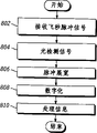
The manner of execution of Fig. 6-8 expression each embodiment of the present invention.Fig. 6 represents the flow chart according to the method for the generation laser communication signal of the preferred embodiments of the present invention.This method is in step 602 beginning, the information that acquisition will send.For example, this information can be single-channel or multiplexing information.In step 604, this information is modulated, produces wide relatively modulated pulse sequence (for example, carrier free video pulse).Next,, the specific edge of each pulse of modulated pulse sequence is detected, so that produce the sequence of very short pulse with the following order of magnitude pulse duration of 200 femtoseconds in step 606.
By the ultra high-speed optical switch, this pulse train is utilized lasing light emitter conversion in step 608, produces very short modulated light pulse train.In step 610, this light pulse sequence is sent to laser detector and this method finishes then.
Fig. 7 represents the flow chart according to the method for the generation laser communication signal of another one embodiment of the present invention.The method of Fig. 7 is particularly suitable for the laser communication of AM modulation signal.This method obtains information to be sent in step 702 beginning.For example, this information can be single-channel or multiplexing information.In step 704, its intensity of the modulated generation of the intensity of laser is according to the laser signal of this information change.
In step 706, utilize the femtosecond pulse signal, the laser pulse of intensity modulated is carried out conversion, produces very short amplitude modulation(PAM) light pulse sequence.In step 708, this light pulse sequence is sent to laser detector and this method finishes.
Fig. 8 represents the flow chart according to the method for the detection laser signal of communication of the preferred embodiments of the present invention.This method receives the femtosecond pulse light signal in step 802 beginning.In step 804, this pulse is carried out detection, produces electrical pulse sequence.In step 806, the broadened pulse duration of this electric pulse for being more suitable for modulating.The method of pulse stretching depends on the type of the employed modulation technique of transmitter.In step 808, the signal of generation is digitized and handles, and in step 810, produces the information that is contained in the received signal.This method finishes.
In a word, method and apparatus of the present invention produces very narrow modulated laser pulse, and this pulse can be passed through lossy medium, and is not subjected to tangible decay.Therefore, method and apparatus of the present invention can be with very high speed by thinking in the past that the too big medium that are not suitable for the two-forty laser communication of loss communicated.
The present invention is described with reference to each embodiment.But those skilled in the art is just recognized and can made change and modification to each preferred embodiment without departing from the scope of the invention.For example, in this manual each of expression handle and the stage can by be described in different classification and organizational form here and carry out, but realize equivalent effect.For those skilled in the art be conspicuous these and other change and revise and certainly will will be included in the scope of the present invention.
Claims (10)
1. method by lossy media communication, this method may further comprise the steps:
Produce the modulated signal of representative input data from least one information source;
Utilize pulse train of this information signal modulation;
Apply this modulated pulse sequence to laser, produce laser pulse, wherein each pulse duration of this pulse train is shorter than 200 femtoseconds; With
Make this laser pulse by lossy medium aim detecting device.
2. according to the desired method of claim 1, wherein the step of modulated pulse trains may further comprise the steps:
This pulse train of pulse position modulation.
3. according to the desired method of claim 1, wherein the step of modulated pulse trains may further comprise the steps:
This pulse train of amplitude modulation(PAM).
4. according to the desired method of claim 1, wherein the step of modulated pulse trains may further comprise the steps:
This pulse train of frequency modulation(FM).
5. according to the desired method of claim 1, wherein the step of modulated pulse trains may further comprise the steps:
This pulse train of phase modulated.
6. according to the desired method of claim 1, wherein the step of modulated pulse trains may further comprise the steps:
Utilize any combination of one group of modulator approach to modulate this pulse train, this modulator approach comprises pulse position modulation, amplitude modulation(PAM), frequency modulation(FM) and phase modulated.
7. method of carrying out information communication by lossy medium, this method may further comprise the steps:
The information signal that generation obtains from least one information source;
Produce the laser signal of intensity modulated by the intensity of utilizing this information signal modulated laser;
Produce the pulse train of fixed rate basically;
Utilize the laser signal of this pulse train modulate intensity modulation, generation has the laser pulse that width is lower than 200 femtoseconds; With
Make this laser pulse by lossy medium aim detecting device.
8. laser transmitter comprises:
The modulated pulse sequencer, this generator produces the pulse train that comprises a plurality of digital input pulses, the information that this digit pulse representative remains to be communicated by letter;
Be connected to the pulse shaping circuit of this pulse-series generator, this circuit produces pulse train, makes the width of each pulse be lower than 200 femtoseconds;
Be used to produce the laser of laser beam;
Be connected to pulse shaping circuit and to the optical switch of laser, this optical switch utilizes Laser Modulation pulse train, produce laser pulse; With
Be connected to the light telescope of optical switch, this telescope makes laser pulse aim detecting device.
9. laser transmitter comprises:
The modulated pulse sequencer, this generator produces the pulse train that comprises a plurality of digital input data pulses, this data pulse representative information to be communicated by letter;
The very short pulse that is connected to pulse-series generator forms circuit, and this generator produces pulse train, makes that when this pulse train was sent out by lossy medium, the pulse duration of each pulse produced the minimal attenuation characteristic; With
Be connected to pulse shaping circuit and the ultra high-speed optical switch that is connected to laser, this optical switch utilizes laser modulation pulse train, produces the laser pulse that is sent by lossy medium by the light telescope.
10. laser detector comprises:
Be used to receive the light telescope of each laser pulse, wherein laser pulse comprises the modulated pulse sequence, and this pulse train comprises having each pulse that is shorter than 200 femtosecond pulse width;
Be connected to the telescopical wideband pulse detector of light, this detector detection laser pulse and conversion light pulse are electric pulse;
Be connected to the stretch circuit of wideband pulse detector, this each electric pulse of circuit broadening is the pulse train with width of suitable demodulation;
Be connected to the analog/digital converter of stretch circuit, being used for the conversion analog signal is digital pulse sequence; With
Be connected to the processor of analog/digital converter, be used for from the digital pulse sequence information extraction.
Applications Claiming Priority (2)
| Application Number | Priority Date | Filing Date | Title |
|---|---|---|---|
| US08/905,760 | 1997-08-04 | ||
| US08/905,760 US6043920A (en) | 1997-08-04 | 1997-08-04 | Method and apparatus for laser communication through a lossy medium |
Publications (1)
| Publication Number | Publication Date |
|---|---|
| CN1269929A true CN1269929A (en) | 2000-10-11 |
Family
ID=25421422
Family Applications (1)
| Application Number | Title | Priority Date | Filing Date |
|---|---|---|---|
| CN98808855A Pending CN1269929A (en) | 1997-08-04 | 1998-06-17 | Method and apparatus for laser communication through lossy medium |
Country Status (14)
| Country | Link |
|---|---|
| US (1) | US6043920A (en) |
| EP (1) | EP1013011B1 (en) |
| JP (1) | JP4188552B2 (en) |
| KR (1) | KR100327925B1 (en) |
| CN (1) | CN1269929A (en) |
| AU (1) | AU7975198A (en) |
| CA (1) | CA2299596A1 (en) |
| DE (1) | DE69831253T2 (en) |
| FR (1) | FR2766997B1 (en) |
| IL (1) | IL134243A (en) |
| IT (1) | IT1299559B1 (en) |
| NO (1) | NO20000595D0 (en) |
| TW (1) | TW387168B (en) |
| WO (1) | WO1999007086A1 (en) |
Cited By (2)
| Publication number | Priority date | Publication date | Assignee | Title |
|---|---|---|---|---|
| CN100373147C (en) * | 2005-12-19 | 2008-03-05 | 中国人民解放军总装备部军械技术研究所 | Field online integrated tester for pulse laser emitter |
| CN100459459C (en) * | 2005-08-04 | 2009-02-04 | 上海交通大学 | Multi-code type adjustable transmitter capable of phase automatic calibration |
Families Citing this family (15)
| Publication number | Priority date | Publication date | Assignee | Title |
|---|---|---|---|---|
| DE19737482A1 (en) * | 1997-08-28 | 1999-03-04 | Alsthom Cge Alcatel | Process for optical transmission over an optical fiber network, and optical transmission network |
| US20010019437A1 (en) * | 1998-05-08 | 2001-09-06 | Hait John N. | Combination photonic time and wavelength division demultiplexing method |
| US6583911B1 (en) * | 1999-10-06 | 2003-06-24 | Dennis R. Alexander | Optical communications by frequency content of femtosecond laser pulses |
| US6661975B1 (en) * | 2000-03-10 | 2003-12-09 | Northrop Grumman Corporation | Multi-rate variable duty cycle modem for use in an optical communication system |
| US6735398B1 (en) * | 2000-03-15 | 2004-05-11 | Hughes Electronics Corporation | Generating methods for single and multi-channel wideband optical analog pulse positioned waveforms |
| WO2002015416A2 (en) | 2000-08-17 | 2002-02-21 | Terabit Communications, L.L.C. | High-speed communications system |
| KR20020056827A (en) * | 2000-12-29 | 2002-07-10 | 김수찬 | Wireless optical communication system |
| US7432517B2 (en) * | 2004-11-19 | 2008-10-07 | Asml Netherlands B.V. | Pulse modifier, lithographic apparatus, and device manufacturing method |
| US7989775B2 (en) * | 2005-08-04 | 2011-08-02 | Lockheed Martin Corporation | Sensor systems and methods using entangled quanta |
| WO2012058571A1 (en) * | 2010-10-29 | 2012-05-03 | Lockheed Martin Corporation | Methods and systems for high bandwidth optical communication |
| EP2615749B1 (en) * | 2011-12-20 | 2017-12-06 | Thales Alenia Space Schweiz AG | Method for optical data transmission from low earth orbit to earth and corresponding communication system |
| US9300398B2 (en) | 2012-01-09 | 2016-03-29 | Attochron, Llc | USPL-FSO lasercom point-to-point and point-to-multipoint optical wireless communication |
| WO2013150716A1 (en) * | 2012-04-03 | 2013-10-10 | パナソニック株式会社 | Visible light reception device and visible light reception method |
| US11777610B2 (en) * | 2018-02-07 | 2023-10-03 | Attochron, Llc | Method and apparatus for ultra-short pulsed laser communication through a lossy medium |
| US11165506B2 (en) * | 2020-01-17 | 2021-11-02 | The Boeing Company | Drone network and method of operating |
Family Cites Families (14)
| Publication number | Priority date | Publication date | Assignee | Title |
|---|---|---|---|---|
| US4764982A (en) * | 1962-07-02 | 1988-08-16 | Pfund Charles E | Secure communication system |
| US3727061A (en) * | 1970-07-06 | 1973-04-10 | Us Army | Pulse laser communication system |
| CH618820A5 (en) * | 1977-09-27 | 1980-08-15 | Ibm | |
| US4399564A (en) * | 1980-02-19 | 1983-08-16 | The United States Of America As Represented By The Secretary Of The Navy | Fiber optic system for transmission of video signals by pulse-frequency-modulation |
| US4656439A (en) * | 1983-09-12 | 1987-04-07 | Wessel John E | System for nanosecond modulation of an infrared laser beam by coherent Stark switching |
| JP2668017B2 (en) * | 1987-12-22 | 1997-10-27 | 竹中エンジニアリング株式会社 | Infrared detector |
| US5038406A (en) * | 1989-09-19 | 1991-08-06 | Gte Goverment Systems Corporation | Secure two-way submarine communication system |
| US5206909A (en) * | 1991-01-18 | 1993-04-27 | Gte Government Systems Corporation | Method for secure PPM-based laser communications |
| DE4207687C2 (en) * | 1992-03-11 | 1996-08-08 | Grundig Emv | Device for optical line-independent signal transmission |
| US5801866A (en) * | 1992-08-27 | 1998-09-01 | Trex Communications Corporation | Laser communication device |
| US5689519A (en) * | 1993-12-20 | 1997-11-18 | Imra America, Inc. | Environmentally stable passively modelocked fiber laser pulse source |
| WO1995023461A1 (en) * | 1994-02-28 | 1995-08-31 | International Business Machines Corporation | Method and apparatus for optical wireless communication |
| US5586714A (en) * | 1994-10-06 | 1996-12-24 | Board Of Regents Of The University Of Nebraska | Method of bonding metal to a non-metal substrate |
| JP3249732B2 (en) * | 1995-12-25 | 2002-01-21 | 株式会社テラテック | Optical pulse generator |
-
1997
- 1997-08-04 US US08/905,760 patent/US6043920A/en not_active Expired - Lifetime
-
1998
- 1998-06-17 WO PCT/US1998/012642 patent/WO1999007086A1/en active IP Right Grant
- 1998-06-17 KR KR1020007001207A patent/KR100327925B1/en not_active IP Right Cessation
- 1998-06-17 AU AU79751/98A patent/AU7975198A/en not_active Abandoned
- 1998-06-17 CA CA002299596A patent/CA2299596A1/en not_active Abandoned
- 1998-06-17 CN CN98808855A patent/CN1269929A/en active Pending
- 1998-06-17 JP JP2000505697A patent/JP4188552B2/en not_active Expired - Fee Related
- 1998-06-17 DE DE69831253T patent/DE69831253T2/en not_active Expired - Lifetime
- 1998-06-17 EP EP98930339A patent/EP1013011B1/en not_active Expired - Lifetime
- 1998-06-17 IL IL13424398A patent/IL134243A/en not_active IP Right Cessation
- 1998-06-25 TW TW087110248A patent/TW387168B/en not_active IP Right Cessation
- 1998-07-13 IT IT98RM000468A patent/IT1299559B1/en active IP Right Grant
- 1998-08-04 FR FR9809992A patent/FR2766997B1/en not_active Expired - Fee Related
-
2000
- 2000-02-04 NO NO20000595A patent/NO20000595D0/en not_active Application Discontinuation
Cited By (2)
| Publication number | Priority date | Publication date | Assignee | Title |
|---|---|---|---|---|
| CN100459459C (en) * | 2005-08-04 | 2009-02-04 | 上海交通大学 | Multi-code type adjustable transmitter capable of phase automatic calibration |
| CN100373147C (en) * | 2005-12-19 | 2008-03-05 | 中国人民解放军总装备部军械技术研究所 | Field online integrated tester for pulse laser emitter |
Also Published As
| Publication number | Publication date |
|---|---|
| NO20000595L (en) | 2000-02-04 |
| CA2299596A1 (en) | 1999-02-11 |
| US6043920A (en) | 2000-03-28 |
| WO1999007086A1 (en) | 1999-02-11 |
| AU7975198A (en) | 1999-02-22 |
| FR2766997B1 (en) | 2000-01-21 |
| FR2766997A1 (en) | 1999-02-05 |
| EP1013011A1 (en) | 2000-06-28 |
| JP2001512918A (en) | 2001-08-28 |
| ITRM980468A0 (en) | 1998-07-13 |
| IL134243A (en) | 2004-02-08 |
| KR100327925B1 (en) | 2002-03-15 |
| EP1013011B1 (en) | 2005-08-17 |
| ITRM980468A1 (en) | 2000-01-13 |
| DE69831253D1 (en) | 2005-09-22 |
| IL134243A0 (en) | 2001-04-30 |
| TW387168B (en) | 2000-04-11 |
| IT1299559B1 (en) | 2000-03-16 |
| KR20010022613A (en) | 2001-03-26 |
| JP4188552B2 (en) | 2008-11-26 |
| NO20000595D0 (en) | 2000-02-04 |
| DE69831253T2 (en) | 2006-01-19 |
Similar Documents
| Publication | Publication Date | Title |
|---|---|---|
| CN1269929A (en) | Method and apparatus for laser communication through lossy medium | |
| CN102724036B (en) | Continuous variable quantum key distribution system and synchronous realization method thereof | |
| US7982861B2 (en) | Time delay and distance measurement | |
| Clark et al. | Performance of a time-and wavelength-interleaved photonic sampler for analog-digital conversion | |
| EP3244554B1 (en) | Single photon communication method and system | |
| CN107359935B (en) | A kind of ultraviolet scatter communication system of non line of sight based on step-by-step counting and its method | |
| CN1073766C (en) | Optical transmission method, transmission apparatus and system with low sensitivity to dispersion | |
| JP2001503210A (en) | Method and apparatus for generating a radio frequency signal | |
| CN104730535A (en) | Vehicle-mounted Doppler laser radar distance measuring method | |
| JPS6115624B2 (en) | ||
| EP0782283A2 (en) | Optical transmitting terminal for optical digital communication using polarization scrambling | |
| CN109932724B (en) | Ultra-wideband laser communication and ranging integrated device and method | |
| CN101551517A (en) | Coherent laser communication system based on wavefront correction | |
| EP0824804A1 (en) | Optical signal transmitter, system and method of transmission | |
| CN1531293A (en) | Method for decreasing peak average power rate | |
| CN110045384B (en) | Laser communication detection device and method | |
| CN1508989A (en) | Method and system for generating low-shaking non-return-to-zero optical data using photo-pulse stretcher | |
| CN1222141C (en) | Effective bandwidth modulation in communication system | |
| CN1124654C (en) | Avalanche photodiode optical receiver | |
| Wang et al. | FPGA-based layered/enhanced ACO-OFDM transmitter | |
| Lyubomirsky et al. | Ideal duobinary generating filter for optically amplified systems | |
| RU2420866C1 (en) | Digital-to-analogue converter with linear transmission | |
| Hansen et al. | A dual-drive Ti: LiNbO/sub 3/Mach-Zehnder modulator used as an optoelectronic logic gate for 10-Gb/s simultaneous multiplexing and modulation | |
| Griffiths et al. | Poissonian communications: free space optical data transfer at the few-photon level | |
| US11018773B1 (en) | Cascaded offset optical modulator for optical communications |
Legal Events
| Date | Code | Title | Description |
|---|---|---|---|
| C06 | Publication | ||
| PB01 | Publication | ||
| C10 | Entry into substantive examination | ||
| SE01 | Entry into force of request for substantive examination | ||
| C02 | Deemed withdrawal of patent application after publication (patent law 2001) | ||
| WD01 | Invention patent application deemed withdrawn after publication | ||
| REG | Reference to a national code |
Ref country code: HK Ref legal event code: GR Ref document number: 1067140 Country of ref document: HK |