JP4188552B2 - Laser communication method and apparatus in lossy media - Google Patents
Laser communication method and apparatus in lossy media Download PDFInfo
- Publication number
- JP4188552B2 JP4188552B2 JP2000505697A JP2000505697A JP4188552B2 JP 4188552 B2 JP4188552 B2 JP 4188552B2 JP 2000505697 A JP2000505697 A JP 2000505697A JP 2000505697 A JP2000505697 A JP 2000505697A JP 4188552 B2 JP4188552 B2 JP 4188552B2
- Authority
- JP
- Japan
- Prior art keywords
- pulse
- laser
- modulating
- optical
- pulse stream
- Prior art date
- Legal status (The legal status is an assumption and is not a legal conclusion. Google has not performed a legal analysis and makes no representation as to the accuracy of the status listed.)
- Expired - Fee Related
Links
- 238000000034 method Methods 0.000 title claims description 51
- 238000004891 communication Methods 0.000 title description 37
- 230000003287 optical effect Effects 0.000 claims description 54
- 238000001208 nuclear magnetic resonance pulse sequence Methods 0.000 description 15
- 238000010586 diagram Methods 0.000 description 8
- 238000005516 engineering process Methods 0.000 description 7
- 230000001960 triggered effect Effects 0.000 description 5
- 238000010521 absorption reaction Methods 0.000 description 4
- 230000000630 rising effect Effects 0.000 description 4
- XLYOFNOQVPJJNP-UHFFFAOYSA-N water Substances O XLYOFNOQVPJJNP-UHFFFAOYSA-N 0.000 description 2
- 239000000443 aerosol Substances 0.000 description 1
- 239000003570 air Substances 0.000 description 1
- 238000013459 approach Methods 0.000 description 1
- 238000007796 conventional method Methods 0.000 description 1
- 238000001514 detection method Methods 0.000 description 1
- 230000000694 effects Effects 0.000 description 1
- 230000007274 generation of a signal involved in cell-cell signaling Effects 0.000 description 1
- 239000003365 glass fiber Substances 0.000 description 1
- 239000004973 liquid crystal related substance Substances 0.000 description 1
- 230000007246 mechanism Effects 0.000 description 1
- 238000012986 modification Methods 0.000 description 1
- 230000004048 modification Effects 0.000 description 1
- 238000012545 processing Methods 0.000 description 1
- 230000000717 retained effect Effects 0.000 description 1
- 230000008054 signal transmission Effects 0.000 description 1
- 239000007787 solid Substances 0.000 description 1
- 239000000725 suspension Substances 0.000 description 1
Images


Classifications
-
- H—ELECTRICITY
- H04—ELECTRIC COMMUNICATION TECHNIQUE
- H04B—TRANSMISSION
- H04B10/00—Transmission systems employing electromagnetic waves other than radio-waves, e.g. infrared, visible or ultraviolet light, or employing corpuscular radiation, e.g. quantum communication
- H04B10/11—Arrangements specific to free-space transmission, i.e. transmission through air or vacuum
Landscapes
- Physics & Mathematics (AREA)
- Electromagnetism (AREA)
- Engineering & Computer Science (AREA)
- Computer Networks & Wireless Communication (AREA)
- Signal Processing (AREA)
- Optical Communication System (AREA)
- Lasers (AREA)
- Telescopes (AREA)
- Devices For Checking Fares Or Tickets At Control Points (AREA)
Description
(発明の属する技術分野)
本発明は一般に無線通信に関し、特に、レーザ信号を利用する無線通信に関する。
【0001】
(背景技術)
地球の大気圏を介した通信を行う無線通信システムは一般に、光学的技術ではなく無線周波数(RF)通信技術を利用する。大気圏における光学信号はその吸収および散乱により著しく減少してしまうことが主な理由である。
【0002】
一方、そのような減衰の影響を実質的に受けない環境下にあっては、光信号は良好に伝播する。例えば、目下開発されている衛星通信では、衛星間でレーザ相互リンク(laser cross-links)を利用している。光学通信で高いビット・レートが得られること、および自由空間において減衰が最少であることにより、レーザ通信はそのような用途に対して適切なものになる。
【0003】
地球の大気圏を介するRFおよび光学通信リンクの両者は、減衰の影響を被る。しかしながら、既存のシステムでは、信号伝送レベルを修正して変調技術を利用することにより、比較的高いビット・レートであってもRF減衰が制御可能であることは実証されている。一方、既存の光学技術では大気圏の減衰を克服することがなされておらず、大気圏を介する高ビット・レート光通信を支持し難いものにしている。
【0004】
既存のシステムにおけるある用途にあっては、低いビット・レートで光通信信号を利用している。たとえば、米国特許番号5,038,406号は、空挺の送信機が海面下の潜水艦にダウン・リンク・パルス変調レーザ信号を伝送する2方向潜水艦通信を開示している。レーザ送信機は、高速パルス排除回路(fast pulse rejection circuit)を含み、これは最小幅(公称値は300nm)より短いパルスをフィルタ処理するものである。このことは、幅広いパルス幅に起因して、煙霧質(aerosols)および障害物を透過する能力を制限してしまう。
【0005】
大気圏におけるレーザ光の減衰(散乱および吸収)が、短いパルス幅信号を通信する既存技術の能力を制限するので、損失性媒体を介した高周波レーザ通信は、未だ実現されていない。このため、吸収および散乱に起因する減衰の問題を克服する、損失性媒体を介する短パルス幅レーザ通信を提供することが望まれている。
【0006】
(発明を実施するための最良の形態)
本発明による方法および装置によれば、極めて狭いパルス幅を有するレーザ通信信号を生成することにより、吸収および散乱に起因する減衰の問題を克服することが可能になる。近年のレーザ技術により挟帯域幅パルスを生成することは可能である。この狭帯域幅パルスは、従来の技術では被っていた減衰に比べて実質的に減衰なく媒体を通過させる特性を有する、ということが実証された。
【0007】
本発明による方法および装置は、この挟帯域パルス幅信号の新規な性質をレーザ通信の分野に応用するものである。本発明の好適実施例によれば、極めて狭い幅の変調されたレーザ・パルスを、顕著な減衰を受けることなく損失性媒体中を伝送させることが可能である。したがって、本発明による方法および装置によれば、かつては損失が大きすぎるために高速レーザ通信を行うことができなかった媒体中を、極めて高いビット・レートで通信することを可能にする。たとえば、本発明による方法および装置は、大気、水、水蒸気、固体障害物、浮遊微粒子(particulate suspension)、ガラス・ファイバその他の媒体中のレーザ通信に利用可能であろう。
【0008】
本発明による方法および装置は、特に、衛星通信に有益であり、この衛星通信は、従来の手法によれば発せられたレーザ信号が大気圏および他の障害物により遮断されてしまうものである。本発明による方法および装置による非常に短いパルス・レーザを利用する衛星−地表および地表−衛星間の通信は、従来の手法に比べて通信品質を向上させるであろう。さらに、本発明による方法および装置は、衛星間または深淵空間(deep space)リンク用の地上通信システムで利用することも可能である。地上通信システムの場合は、大気圏の低位置における信号損失が重大であることに起因して、発明の効果は最大のものとなるであろう。
【0009】
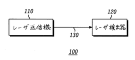
図1は本発明の好適実施例による通信システム100を示す。好適実施例にあっては、通信システム100は、レーザ送信機110およびレーザ検出器120を備える。レーザ送信機110は、本発明の実施例に従ってレーザ信号を生成し、そのレーザ信号をリンク130を介してレーザ検出器120に伝送する。リンク130には、例えば先に述べたような損失性媒体が介在する。
【0010】
後述するように、生成されたレーザ信号は、200フェムト(fempto)秒以下のパルス幅を有する変調された光学パルス・シーケンスである。このような狭いパルス幅を有する光学パルスは、ある性質を有し、その性質とは、従来のシステムによれば被っていたであろう減衰と同程度のものを被ることなく、パルスが損失性媒体中を伝播することが可能である、というものである。本発明の方法および装置は、200フェムト秒より大きい短パルスを利用するシステムでも利用することが可能であろう。このようなシステムにあっては、本発明の方法および装置による利益は依然として存在するであろうが、少ないであろう。好適実施例にあっては、パルス幅は40ないし60フェムト秒の範囲内にある。レーザ検出器120が受信した後、この信号に含まれる情報は以下に説明するようにして抽出される。
【0011】
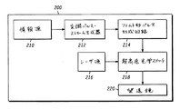
図2は本発明の好適実施例によるレーザ送信機200の簡略ブロック図を示す。好適実施例にあっては、レーザ送信機200は、情報源210、変調パルス・ストリーム生成器212、フェムト秒パルス形成回路214、超高速光学スイッチ218、レーザ源216および望遠鏡220を備える。
【0012】
情報源210は、ディジタル情報またはディジタル化されたアナログ情報の任意の情報源とすることが可能である。この情報は、信号源からのデータを表わすことが可能であり、任意の多重化されたディジタル情報源より成ることもかのうである。たとえば、情報源210は、周波数分割多元アクセス(FDMA)、時分割多元アクセス(TDMA)、符号分割多元アクセス(CDMA)および他の既存の手法ならびにこれらの結合を利用して、多重化されたディジタル情報とすることも可能である。
【0013】
情報源210は、ディジタル情報またはディジタル化されたアナログ情報を、変調パルス・ストリーム生成器212(MPSG)に提供する。MPSG212は、比較的広いパルスの変調パルス・ストリームを生成する。例えばそのパルスは、マイクロ秒ないしナノ秒程度の大きさのパルス幅を有する通常の映像パルスと同様のものとすることが可能である。MPSG212は周知の各種の変調技術またはそれらの組合わせを利用することが可能である。例えばMPSG212は、パルス位置(pulse position)変調または周波数変調を利用することが可能である。
【0014】
好適実施例にあっては、変調されたパルス・ストリームは、フェムト秒パルス形成回路214(FPFC)に供給される。FPFC214は200フェムト秒以下の大きさの幅の極めて短いパルスを形成し、毎度FPFC214はその変調されたパルス・ストリームの特定のエッジを検出する。好適実施例にあっては、FPFC214は立ち上がりエッジでトリガされるが、他の実施例にあっては立下エッジで、または立上および立下エッジの両者でトリガすることも可能である。
【0015】
他の実施例にあっては、ブロック212および214を単一のステップ(段)とすることも可能である。すなわち、情報源210により供給されるデータに基づいて極短パルスを直接的に形成および変調することも可能である。
【0016】
FPFC214の出力は超高速光学スイッチ218(UHSOS)に結合される。UHSOS218は、レーザ源216からの実質的に一定な振幅/周波数のレーザを受信することに加えて、FPFC214からフェムト秒パルスを受信する。レーザ源216は、例えば810-850ナノメートルまたは1.05-1.5マイクロメートルの範囲内とすることが可能な波長のレーザを供給するが、他の波長を採用することも可能である。
【0017】
UHSOS218がFPFC214からフェムト秒パルスを受信する度に、UHSOS218はレーザ源216を切り替え、極めて短い変調された光学パルス・シーケンスを生成する。この光学パルス・シーケンスは望遠鏡220に与えられ、検出器に向かう光学パルスを検出する。
【0018】
図3は本発明の好適実施例による振幅変調(AM)レーザ送信機300の簡略ブロック図を示す。好適実施例にあっては、AMレーザ送信機300は、AM変調パルス源302、超高速光学スイッチ304、パルス・ストリーム生成器306、フェムト秒パルス形成回路302および望遠鏡310をを備える。
【0019】
好適実施例にあっては、AM変調パルス源302は、情報源320、強度変調器322およびレーザ324を備える。情報源320はAM変調に適切な波形を供給する。例えば情報源320は、AM変調されたパルス・シーケンスまたはアナログ波形を供給することが可能である。情報は、シングル・チャネルとすることも多重化することも可能である。
【0020】
AM波形は強度変調器322に供給される。強度変調器322は、レーザ324により生成されたレーザ波形の強度を変調し、これはレーザ源の駆動特性(drive characteristic)を強度に比例して変化させることにより行われる。強度変調器322はレーザ光強度を変調することが可能であり、これは例えば、入力バイアス電流量を調整したり、電圧を変化させたり、あるいは当該技術分野で周知の変調手法を実行することにより行うことが可能である。レーザ324は連続的なレーザ信号を出力し、この信号は情報源320により供給された情報に基づいて強度が変化するものである。
【0021】
図4は本発明の好適実施例によるAM変調されたパルス源送信機400の簡略ブロック図を示す。他の実施例にあってはAMパルス源400は例えば図3に示されるAM変調パルス源302を利用することも可能である。
【0022】
AM変調パルス源302(図3)とは異なり、AM変調パルス源400は、光学線形減衰器406により変調された一定強度のレーザを利用する。光学線形減衰器406は、例えば、液晶技術を利用してレーザ強度を変調することが可能である。光学線形減衰器406は、情報源402により供給された情報に比例してレーザ光強度を変化させる(このことは、上述した情報源320と実質的に同様である。)。光学線形減衰器406は連続的なレーザ信号を出力し、この信号は情報源402により供給された情報に基づいて強度が変化するものである。
【0023】
図3を参照すると、(AM変調パルス源302または他の手段により生成された)連続的なレーザ信号は超高速光学スイッチ304(UHSOS)に入力されている。UHSOS304は、パルス・ストリーム生成器306およびフェムト秒パルス形成回路308(FPFC)からの信号も受信する。
【0024】
パルス・ストリーム生成器306は、あるパルス・レートで実質的に連続的なパルス・ストリームを供給し、そのレートは情報源320により供給される情報の帯域幅のものより高いものである。パルス・ストリームはFPFC308により検出され、これは200フェムト秒以下の大きさの幅である極めて短いパルスを形成し、その連続パルス・ストリームの特定のパルス・エッジをFPFC308が毎度検出する。好適実施例にあっては、FPFC308は立ち上がりエッジでトリガされるが、他の実施例にあってはFPFC308が立ち下がりエッジで、または立上および立下エッジの両者でトリガすることも可能である。
【0025】
FPFC308の出力はUHSOS304に供給される。UHSOS304は、AM変調パルス源302または400からの強度変調レーザ信号を受信することに加えて、FPFC308からフェムト秒パルスを受信する。UHSOS304がFPFC308からフェムト秒パルスを受信するたびに、UHSOS304はAM変調パルス源302または400を切り替え、極めて短い振幅変調された光学パルス・シーケンスを生成する。この光学パルス・シーケンスは望遠鏡220に供給され、この望遠鏡は検出器に向かう光学パルスを検出するものである。
【0026】
パルス位置、振幅および周波数変調技術を利用するものとして本発明による装置を説明してきたが、本発明による方法および装置による利益を享受する観点からは、位相変調のような他の変調技術を利用することも可能である。
【0027】
FPFC214,308およびUHSOS218,304を利用して極めて狭いパルス幅を有する変調された向学心号を生成することによって、本発明による方法および装置は、送信機200,300から図5に示すような検出器までの間に介在する損失性媒体における高速レーザ通信を可能にする。
【0028】
図5は本発明の好適実施例によるレーザ検出器500の簡略ブロック図を示す。好適実施例にあっては、レーザ検出器500は、光学望遠鏡502、広帯域光学検出器504、パルス延長回路(pulse stretching circuit)506、アナログ・ディジタル(A/D)変換器508およびディジタル信号処理装置510(DSP)を備える。
【0029】
光学望遠鏡502は、図2-4に示されるようなレーザ送信機により発せられたような信号を受信する。この信号は広帯域光学検出器504に供給され、その光学信号が電気的なパルス・シーケンス(例えば、キャリアのない映像パルス)に変換される。これらのパルスはUHSOS218,304(図2,3)により発せられたフェムト秒パルスと実質的に同様のものとなるであろう。広帯域光学検出器504は、例えばアバランシェ・フォトダイオードより成る。
【0030】
パルス延長回路506は電気的なパルス・シーケンスを受信し、それを復調に一層適した幅に延長する(例えば、マイクロ‐ナノ秒の範囲)。したがって、パルス延長回路506の動作は、送信機で使用される変調技術に依存して異なるものとなる。
【0031】
例えば、様々な実施例中の図2に示されるような送信機を使用するシステムにあっては、広帯域光学検出器504によりトリガされる度に、パルス延長回路506は一定の振幅パルスを生成するであろう。この一定の振幅パルスは、MPSG212(図2)により発せられる信号のタイミングを保持することが好ましい。このような実施例にあっては、パルス延長回路506は例えば単安定マルチバイブレータとすることが可能であろう。
【0032】
図3-4に示されるような送信機を利用するシステムにあっては、パルス延長回路506はピーク検出/保持回路とすることが可能であろう。一実施例にあっては、異なるレベルを有するパルスが受信されるまで、各々受信されたパルス振幅を有する信号が保持される。
【0033】
パルス延長回路506で使用されるパルス延長方法に拘わらず、出力信号はA/D変換器508によりサンプルされる。好適実施例にあっては、A/D変換器508は、ライン512によりパルス延長回路506からトリガ信号を受信し、この信号は、パルス延長された信号をいつサンプルするかをA/D変換器508に知らせるものである。他の実施例にあっては、A/D変換器508は、広帯域光学検出器504からトリガ信号を受信することも可能であり、またはサンプル・タイミングを決定するための他の機構を利用することも可能である。
【0034】
A/D変換器508は、送信機において信号を変調するために使用された手法にふさわしい手法を利用して信号を変換するよう構築される必要がある。A/D変換器508はサンプル信号をDSP510に提供し、このDSPは信号を復調して実質的に当初伝送された情報を得るものである。DSP510は、送信機の信号生成手法にふさわしいディジタル波形処理を行う。
【0035】
図6-8は本発明を実行するための方法を説明するためのものである。図6は本発明の好適実施例によるレーザ通信信号を生成する方法のフローチャートを示す。この方法は、伝送すべき情報を得るステップ602から始まる。この情報は例えば単一チャネルまたは多重化された情報とすることが可能である。ステップ604において、情報は変調され、変調された比較的広いパルスのパルス・ストリームを生成する(例えば、キャリアのない映像パルス)。次に、ステップ606において、変調されたパルス・ストリームにおけるパルスの特定のエッジが検出され、200フェムト秒以下の大きさのパルス幅を有する極短パルス・シーケンスを生成する。
【0036】
このパルス・シーケンスはステップ608においてレーザ源を利用して超高速光学スイッチにより切り替えられ、極めて短い変調された光学パルスのシーケンスを得る。この光学パルス・シーケンスは、ステップ610において、レーザ検出器に伝送され、このフローは終了する。
【0037】
図7は本発明の他の実施例によるレーザ通信信号を生成する方法のフローチャートを示す。図7による方法は、AM変調された信号のレーザ通信に特に適している。この方法は、伝送すべき情報を得るステップ702から始まる。この情報は例えば単一チャネルまたは多重化された情報とすることが可能である。ステップ704において、レーザの強度が変調され、その情報に関連する強度で変化するレーザ信号が生成される。
【0038】
強度変調されたレーザ・パルスはステップ706においてフェムト秒パルス信号を利用して切り替えられ、極めて短い振幅変調光学パルス・シーケンスを得る。ステップ608において、光学パルス・シーケンスはレーザ検出器に伝送され、このフローは終了する。
【0039】
図8は本発明の好適実施例によるレーザ通信信号の検出方法のフローチャートを示す。フェムト秒パルスの光学信号がステップ802において受信されると、この方法が始まる。パルスはステップ804において光学的に検出され、電気的なパルス・シーケンスが生成される。電気的なパルスは、その後ステップ806において変調に一層適切なパルス幅に延長される。パルスを延長する手法は、送信機で使用される変調手法の種別に依存する。ステップ808において、信号がディジタル化され、ステップ810において処理され、受信信号中に含まれる情報が復元される。そして、この方法が終了する。
【0040】
要するに、本発明による方法および装置は、極めて挟帯域の変調されたレーザ・パルスを生成し、このパルスは、大きな減衰を被ることなく損失性媒体中を伝播することが可能である。本発明による方法および装置は、従来は損失が大きすぎるために高速レーザ通信に適切でないと考えられていた媒体中であっても、極めて高速な通信を行うことを可能にする。
【0041】
以上本発明を特定の実施例に関連して説明してきたが、当業者であれば、本発明の精神から逸脱することなく様々な改良や変形をすることが可能であろう。
【図面の簡単な説明】
【図1】 本発明の好適実施例による通信システムを示す。
【図2】 本発明の好適実施例によるレーザ送信機の簡略ブロック図を示す。
【図3】 本発明の好適実施例による振幅変調レーザ送信機の簡略ブロック図を示す。
【図4】 本発明の好適実施例によるAM変調されたパルス源送信機の簡略ブロック図を示す。
【図5】 本発明の好適実施例によるレーザ検出器の簡略ブロック図を示す。
【図6】 本発明の好適実施例によるレーザ通信信号を生成する方法のフローチャートを示す。
【図7】 本発明の他の実施例によるレーザ通信信号を生成する方法のフローチャートを示す。
【図8】 本発明の好適実施例によるレーザ通信信号の検出方法のフローチャートを示す。(Technical field to which the invention belongs)
The present invention relates generally to wireless communications, and more particularly to wireless communications utilizing laser signals.
[0001]
(Background technology)
Wireless communication systems that communicate through the Earth's atmosphere generally use radio frequency (RF) communication technology rather than optical technology. The main reason is that optical signals in the atmosphere are significantly reduced by their absorption and scattering.
[0002]
On the other hand, an optical signal propagates satisfactorily in an environment that is not substantially affected by such attenuation. For example, currently developed satellite communications utilize laser cross-links between satellites. Laser communication is suitable for such applications because of the high bit rates that can be achieved in optical communication and the least attenuation in free space.
[0003]
Both RF and optical communication links through the Earth's atmosphere are subject to attenuation. However, it has been demonstrated that existing systems can control RF attenuation even at relatively high bit rates by modifying the signal transmission level and using modulation techniques. On the other hand, existing optical technologies do not overcome atmospheric attenuation, making it difficult to support high bit rate optical communications via the atmosphere.
[0004]
In some applications in existing systems, optical communication signals are used at a low bit rate. For example, US Pat. No. 5,038,406 discloses a two-way submarine communication in which an airborne transmitter transmits a downlink pulse modulated laser signal to a submarine submarine. The laser transmitter includes a fast pulse rejection circuit, which filters pulses shorter than the minimum width (nominal value is 300 nm). This limits the ability to penetrate aerosols and obstacles due to the wide pulse width.
[0005]
Since attenuation (scattering and absorption) of laser light in the atmosphere limits the ability of existing technology to communicate short pulse width signals, high frequency laser communication via lossy media has not yet been realized. For this reason, it is desirable to provide short pulse width laser communication via lossy media that overcomes the problem of attenuation due to absorption and scattering.
[0006]
(Best Mode for Carrying Out the Invention)
The method and apparatus according to the invention makes it possible to overcome attenuation problems due to absorption and scattering by generating a laser communication signal having a very narrow pulse width. It is possible to generate narrow bandwidth pulses with recent laser technology. It has been demonstrated that this narrow bandwidth pulse has the property of passing the medium substantially without attenuation compared to the attenuation experienced in the prior art.
[0007]
The method and apparatus according to the present invention apply the novel nature of this narrowband pulse width signal to the field of laser communications. In accordance with the preferred embodiment of the present invention, it is possible to transmit a very narrow width modulated laser pulse through a lossy medium without significant attenuation. Therefore, the method and apparatus according to the present invention enables communication at a very high bit rate in a medium that was once unable to perform high speed laser communication due to excessive loss. For example, the method and apparatus according to the present invention may be used for laser communications in air, water, water vapor, solid obstacles, particulate suspension, glass fibers and other media.
[0008]
The method and apparatus according to the present invention are particularly useful for satellite communications, where laser signals emitted according to conventional techniques are blocked by the atmosphere and other obstacles. Satellite-to-surface and surface-to-satellite communications utilizing very short pulse lasers with the method and apparatus according to the present invention will improve communication quality compared to conventional approaches. Furthermore, the method and apparatus according to the invention can also be used in terrestrial communication systems for intersatellite or deep space links. In the case of a terrestrial communication system, the effect of the invention will be maximized due to the significant signal loss at low locations in the atmosphere.
[0009]
FIG. 1 shows a
[0010]
As will be described later, the generated laser signal is a modulated optical pulse sequence having a pulse width of 200 femto seconds or less. An optical pulse with such a narrow pulse width has certain properties that are lossy without suffering from the same amount of attenuation that would have been experienced by conventional systems. It is possible to propagate through the medium. The method and apparatus of the present invention may also be used in systems that utilize short pulses greater than 200 femtoseconds. In such a system, the benefits of the method and apparatus of the present invention will still exist but will be small. In the preferred embodiment, the pulse width is in the range of 40 to 60 femtoseconds. After the
[0011]
FIG. 2 shows a simplified block diagram of a
[0012]
The
[0013]
[0014]
In the preferred embodiment, the modulated pulse stream is provided to a femtosecond pulse forming circuit 214 (FPFC). The
[0015]
In other embodiments, blocks 212 and 214 may be a single step. That is, it is possible to directly form and modulate ultrashort pulses based on data supplied by the
[0016]
The output of the
[0017]
Each
[0018]
FIG. 3 shows a simplified block diagram of an amplitude modulation (AM)
[0019]
In the preferred embodiment, the AM modulated
[0020]
The AM waveform is supplied to the
[0021]
FIG. 4 shows a simplified block diagram of an AM modulated
[0022]
Unlike the AM modulated pulse source 302 (FIG. 3), the AM modulated
[0023]
Referring to FIG. 3, a continuous laser signal (generated by an AM modulated
[0024]
The
[0025]
The output of FPFC308 is supplied to UHSOS304.
[0026]
Although the apparatus according to the present invention has been described as utilizing pulse position, amplitude and frequency modulation techniques, other modulation techniques such as phase modulation are utilized from the point of view of benefiting from the method and apparatus according to the present invention. It is also possible.
[0027]
By using FPFC 214,308 and UHSOS 218,304 to generate a modulated centripetal signal with a very narrow pulse width, the method and apparatus according to the present invention can be used as a detector as shown in FIG. Enables high-speed laser communication in a lossy medium intervening in between.
[0028]
FIG. 5 shows a simplified block diagram of a laser detector 500 according to a preferred embodiment of the present invention. In the preferred embodiment, the laser detector 500 comprises an optical telescope 502, a broadband optical detector 504, a pulse stretching circuit 506, an analog-to-digital (A / D) converter 508, and a digital signal processor. Equipped with 510 (DSP).
[0029]
The optical telescope 502 receives a signal as emitted by a laser transmitter as shown in FIG. 2-4. This signal is supplied to a broadband optical detector 504, which converts the optical signal into an electrical pulse sequence (eg, a video pulse without a carrier). These pulses will be substantially similar to the femtosecond pulses emitted by UHSOS 218,304 (FIGS. 2, 3). The broadband optical detector 504 is composed of, for example, an avalanche photodiode.
[0030]
The pulse extension circuit 506 receives an electrical pulse sequence and extends it to a width that is more suitable for demodulation (eg, in the micro-nanosecond range). Therefore, the operation of the pulse extension circuit 506 varies depending on the modulation technique used in the transmitter.
[0031]
For example, in a system using a transmitter such as that shown in FIG. 2 in various embodiments, the pulse extension circuit 506 generates a constant amplitude pulse each time triggered by the broadband optical detector 504. Will. This constant amplitude pulse preferably retains the timing of the signal emitted by the MPSG 212 (FIG. 2). In such an embodiment, the pulse extension circuit 506 could be a monostable multivibrator, for example.
[0032]
In a system utilizing a transmitter as shown in FIG. 3-4, the pulse extension circuit 506 could be a peak detection / holding circuit. In one embodiment, a signal with each received pulse amplitude is retained until a pulse with a different level is received.
[0033]
Regardless of the pulse extension method used in pulse extension circuit 506, the output signal is sampled by A / D converter 508. In the preferred embodiment, A / D converter 508 receives a trigger signal from pulse extension circuit 506 via line 512, which signal indicates when to sample the pulse extended signal. Tell 508. In other embodiments, the A / D converter 508 may receive a trigger signal from the broadband optical detector 504 or utilize other mechanisms for determining sample timing. Is also possible.
[0034]
The A / D converter 508 needs to be constructed to convert the signal using a technique suitable for the technique used to modulate the signal at the transmitter. The A / D converter 508 provides a sample signal to the DSP 510, which demodulates the signal to obtain substantially the originally transmitted information. The DSP 510 performs digital waveform processing suitable for the signal generation method of the transmitter.
[0035]
6-8 are for explaining the method for carrying out the present invention. FIG. 6 shows a flowchart of a method for generating a laser communication signal according to a preferred embodiment of the present invention. The method begins at
[0036]
This pulse sequence is switched by the ultrafast optical switch utilizing a laser source in
[0037]
FIG. 7 shows a flowchart of a method for generating a laser communication signal according to another embodiment of the present invention. The method according to FIG. 7 is particularly suitable for laser communication of AM modulated signals. The method begins at
[0038]
The intensity modulated laser pulse is switched using a femtosecond pulse signal in
[0039]
FIG. 8 shows a flowchart of a method for detecting a laser communication signal according to a preferred embodiment of the present invention. The method begins when an optical signal of femtosecond pulses is received in step 802. The pulses are optically detected at
[0040]
In summary, the method and apparatus according to the present invention produces a very narrow-band modulated laser pulse that can propagate through a lossy medium without incurring significant attenuation. The method and apparatus according to the present invention enables extremely high speed communication even in media that were previously considered unsuitable for high speed laser communication due to excessive loss.
[0041]
Although the invention has been described with reference to specific embodiments, those skilled in the art will be able to make various improvements and modifications without departing from the spirit of the invention.
[Brief description of the drawings]
FIG. 1 shows a communication system according to a preferred embodiment of the present invention.
FIG. 2 shows a simplified block diagram of a laser transmitter according to a preferred embodiment of the present invention.
FIG. 3 shows a simplified block diagram of an amplitude modulated laser transmitter according to a preferred embodiment of the present invention.
FIG. 4 shows a simplified block diagram of an AM modulated pulse source transmitter according to a preferred embodiment of the present invention.
FIG. 5 shows a simplified block diagram of a laser detector according to a preferred embodiment of the present invention.
FIG. 6 shows a flowchart of a method for generating a laser communication signal according to a preferred embodiment of the present invention.
FIG. 7 shows a flowchart of a method for generating a laser communication signal according to another embodiment of the present invention.
FIG. 8 shows a flowchart of a method for detecting a laser communication signal according to a preferred embodiment of the present invention.
Claims (9)
少なくとも1つの情報源から入力データを表現する変調された信号を生成する段階;
情報信号と共にパルス・ストリームを変調する段階;
変調されたパルス・ストリームを利用してレーザ光学パルスを生成する段階であって、パルス・ストリームの各パルスのパルス幅が200フェムト秒以下であるところの段階;および
損失性媒体を介して無線リンクによりレーザ光学パルスを検出器に方向付ける段階;
より成ることを特徴とする方法。A method for communicating information over a lossy medium over a wireless link, the method comprising:
Generating a modulated signal representing input data from at least one information source;
Modulating the pulse stream with the information signal;
Using a modulated pulse stream to generate laser optical pulses, wherein the pulse width of each pulse in the pulse stream is less than or equal to 200 femtoseconds; and a wireless link via a lossy medium Directing the laser optical pulse to the detector by:
A method characterized by comprising:
少なくとも1つの情報源から導出された情報信号を生成する段階;
前記情報信号を利用してレーザの強度を変調することにより、強度変調されたレーザ信号を生成する段階;
実質的に固定レートのパルス・ストリームを生成する段階;
前記強度変調されたレーザ信号を前記パルス・ストリームと共に変調し、200フェムト秒以下の幅を有するレーザ光学パルスを生成する段階;および
損失性媒体を介して無線リンクによりレーザ光学パルスを検出器に方向付ける段階;
より成ることを特徴とする方法。A method for communicating information over a lossy medium over a wireless link, the method comprising:
Generating an information signal derived from at least one information source;
Generating an intensity-modulated laser signal by modulating the intensity of the laser using the information signal;
Generating a substantially fixed rate pulse stream;
Modulating the intensity modulated laser signal with the pulse stream to generate a laser optical pulse having a width of 200 femtoseconds or less; and directing the laser optical pulse to the detector by a wireless link through a lossy medium Attaching stage;
A method characterized by comprising:
通信すべき情報を表現する多数のディジタル入力データ・パルスより成るパルス・ストリームを生成する変調パルス・ストリーム生成器;
前記パルス・ストリーム生成器に結合され、各パルスのパルス幅が200フェムト秒以下であるようなパルス・ストリームを生成するパルス形成回路;
レーザ・ビームを生成するレーザ;
前記パルス形成回路および前記レーザに結合され、前記パルス・ストリームを変調してレーザ光学パルスを生成する光学スイッチ;および
前記光学スイッチに結合され、損失性媒体を介して無線リンクにより前記レーザ光学パルスを検出器に方向付ける望遠鏡;
を備えることを特徴とするレーザ送信機。Laser transmitter:
A modulated pulse stream generator that generates a pulse stream consisting of a number of digital input data pulses representing the information to be communicated;
A pulse forming circuit coupled to the pulse stream generator for generating a pulse stream such that the pulse width of each pulse is 200 femtoseconds or less;
A laser that generates a laser beam;
An optical switch coupled to the pulse forming circuit and the laser and modulating the pulse stream to generate a laser optical pulse; and coupled to the optical switch and transmitting the laser optical pulse by a wireless link via a lossy medium A telescope pointing to the detector;
A laser transmitter comprising:
損失性媒体を介して無線リンクによりレーザ光学パルスを受信する光学望遠鏡であって、前記レーザ光学パルスは、200フェムト秒以下のパルス幅を有するパルスを含む変調パルス・ストリームより成るところの光学望遠鏡;An optical telescope for receiving laser optical pulses over a lossy medium over a wireless link, the laser optical pulses comprising a modulated pulse stream comprising pulses having a pulse width of 200 femtoseconds or less;
前記光学望遠鏡に結合され、前記レーザ光学パルスを検出し、前記光学パルスを電気的パルスに変換する広帯域光学検出器:A broadband optical detector coupled to the optical telescope for detecting the laser optical pulse and converting the optical pulse into an electrical pulse:
前記広帯域光学検出器に結合され、前記電気的パルスを、復調に適切な幅を有するパルス・ストリームに延長するパルス延長回路;A pulse extension circuit coupled to the broadband optical detector and extending the electrical pulse into a pulse stream having a width suitable for demodulation;
前記パルス延長回路に結合され、アナログ信号をディジタル・パルス・ストリームに変換するアナログ・ディジタル変換器;およびAn analog to digital converter coupled to said pulse extension circuit for converting an analog signal into a digital pulse stream; and
前記アナログ・ディジタル変換器に結合され、前記ディジタル・パルス・ストリームから情報を抽出するプロセッサ;A processor coupled to the analog to digital converter for extracting information from the digital pulse stream;
を備えることを特徴とするレーザ検出器。A laser detector comprising:
Applications Claiming Priority (3)
| Application Number | Priority Date | Filing Date | Title |
|---|---|---|---|
| US08/905,760 | 1997-08-04 | ||
| US08/905,760 US6043920A (en) | 1997-08-04 | 1997-08-04 | Method and apparatus for laser communication through a lossy medium |
| PCT/US1998/012642 WO1999007086A1 (en) | 1997-08-04 | 1998-06-17 | Method and apparatus for laser communication through a lossy medium |
Publications (2)
| Publication Number | Publication Date |
|---|---|
| JP2001512918A JP2001512918A (en) | 2001-08-28 |
| JP4188552B2 true JP4188552B2 (en) | 2008-11-26 |
Family
ID=25421422
Family Applications (1)
| Application Number | Title | Priority Date | Filing Date |
|---|---|---|---|
| JP2000505697A Expired - Fee Related JP4188552B2 (en) | 1997-08-04 | 1998-06-17 | Laser communication method and apparatus in lossy media |
Country Status (14)
| Country | Link |
|---|---|
| US (1) | US6043920A (en) |
| EP (1) | EP1013011B1 (en) |
| JP (1) | JP4188552B2 (en) |
| KR (1) | KR100327925B1 (en) |
| CN (1) | CN1269929A (en) |
| AU (1) | AU7975198A (en) |
| CA (1) | CA2299596A1 (en) |
| DE (1) | DE69831253T2 (en) |
| FR (1) | FR2766997B1 (en) |
| IL (1) | IL134243A (en) |
| IT (1) | IT1299559B1 (en) |
| NO (1) | NO20000595D0 (en) |
| TW (1) | TW387168B (en) |
| WO (1) | WO1999007086A1 (en) |
Families Citing this family (18)
| Publication number | Priority date | Publication date | Assignee | Title |
|---|---|---|---|---|
| DE19737482A1 (en) * | 1997-08-28 | 1999-03-04 | Alsthom Cge Alcatel | Process for optical transmission over an optical fiber network, and optical transmission network |
| US20010019437A1 (en) * | 1998-05-08 | 2001-09-06 | Hait John N. | Combination photonic time and wavelength division demultiplexing method |
| US6583911B1 (en) * | 1999-10-06 | 2003-06-24 | Dennis R. Alexander | Optical communications by frequency content of femtosecond laser pulses |
| US6661975B1 (en) * | 2000-03-10 | 2003-12-09 | Northrop Grumman Corporation | Multi-rate variable duty cycle modem for use in an optical communication system |
| US6735398B1 (en) * | 2000-03-15 | 2004-05-11 | Hughes Electronics Corporation | Generating methods for single and multi-channel wideband optical analog pulse positioned waveforms |
| WO2002015416A2 (en) * | 2000-08-17 | 2002-02-21 | Terabit Communications, L.L.C. | High-speed communications system |
| KR20020056827A (en) * | 2000-12-29 | 2002-07-10 | 김수찬 | Wireless optical communication system |
| US7432517B2 (en) * | 2004-11-19 | 2008-10-07 | Asml Netherlands B.V. | Pulse modifier, lithographic apparatus, and device manufacturing method |
| CN100459459C (en) * | 2005-08-04 | 2009-02-04 | 上海交通大学 | Multi-code type adjustable transmitter capable of phase automatic calibration |
| US7989775B2 (en) * | 2005-08-04 | 2011-08-02 | Lockheed Martin Corporation | Sensor systems and methods using entangled quanta |
| CN100373147C (en) * | 2005-12-19 | 2008-03-05 | 中国人民解放军总装备部军械技术研究所 | Field online integrated tester for pulse laser emitter |
| WO2012058571A1 (en) * | 2010-10-29 | 2012-05-03 | Lockheed Martin Corporation | Methods and systems for high bandwidth optical communication |
| EP2615749B1 (en) * | 2011-12-20 | 2017-12-06 | Thales Alenia Space Schweiz AG | Method for optical data transmission from low earth orbit to earth and corresponding communication system |
| CN104160640B (en) | 2012-01-09 | 2017-07-14 | 阿托隆有限责任公司 | USPL FSO laser communications are point-to-point and point-to-multipoint optical wireless communication |
| WO2013150716A1 (en) * | 2012-04-03 | 2013-10-10 | パナソニック株式会社 | Visible light reception device and visible light reception method |
| US11777610B2 (en) | 2018-02-07 | 2023-10-03 | Attochron, Llc | Method and apparatus for ultra-short pulsed laser communication through a lossy medium |
| US11165506B2 (en) * | 2020-01-17 | 2021-11-02 | The Boeing Company | Drone network and method of operating |
| CN118367988B (en) * | 2024-06-18 | 2024-09-06 | 长春通视光电技术股份有限公司 | PPM pulse type laser communication device and method based on serial port protocol |
Family Cites Families (14)
| Publication number | Priority date | Publication date | Assignee | Title |
|---|---|---|---|---|
| US4764982A (en) * | 1962-07-02 | 1988-08-16 | Pfund Charles E | Secure communication system |
| US3727061A (en) * | 1970-07-06 | 1973-04-10 | Us Army | Pulse laser communication system |
| CH618820A5 (en) * | 1977-09-27 | 1980-08-15 | Ibm | |
| US4399564A (en) * | 1980-02-19 | 1983-08-16 | The United States Of America As Represented By The Secretary Of The Navy | Fiber optic system for transmission of video signals by pulse-frequency-modulation |
| US4656439A (en) * | 1983-09-12 | 1987-04-07 | Wessel John E | System for nanosecond modulation of an infrared laser beam by coherent Stark switching |
| DE3884385T2 (en) * | 1987-12-22 | 1994-05-05 | Takenaka Eng Co Ltd | INFRARED DETECTOR. |
| US5038406A (en) * | 1989-09-19 | 1991-08-06 | Gte Goverment Systems Corporation | Secure two-way submarine communication system |
| US5206909A (en) * | 1991-01-18 | 1993-04-27 | Gte Government Systems Corporation | Method for secure PPM-based laser communications |
| DE4207687C2 (en) * | 1992-03-11 | 1996-08-08 | Grundig Emv | Device for optical line-independent signal transmission |
| US5801866A (en) * | 1992-08-27 | 1998-09-01 | Trex Communications Corporation | Laser communication device |
| US5689519A (en) * | 1993-12-20 | 1997-11-18 | Imra America, Inc. | Environmentally stable passively modelocked fiber laser pulse source |
| DE69425000T2 (en) * | 1994-02-28 | 2000-12-07 | Ibm Deutschland Informationssysteme Gmbh | METHOD AND DEVICE FOR WIRELESS OPTICAL TRANSMISSION |
| US5586714A (en) * | 1994-10-06 | 1996-12-24 | Board Of Regents Of The University Of Nebraska | Method of bonding metal to a non-metal substrate |
| JP3249732B2 (en) * | 1995-12-25 | 2002-01-21 | 株式会社テラテック | Optical pulse generator |
-
1997
- 1997-08-04 US US08/905,760 patent/US6043920A/en not_active Expired - Lifetime
-
1998
- 1998-06-17 EP EP98930339A patent/EP1013011B1/en not_active Expired - Lifetime
- 1998-06-17 DE DE69831253T patent/DE69831253T2/en not_active Expired - Lifetime
- 1998-06-17 KR KR1020007001207A patent/KR100327925B1/en not_active Expired - Fee Related
- 1998-06-17 CA CA002299596A patent/CA2299596A1/en not_active Abandoned
- 1998-06-17 WO PCT/US1998/012642 patent/WO1999007086A1/en not_active Ceased
- 1998-06-17 JP JP2000505697A patent/JP4188552B2/en not_active Expired - Fee Related
- 1998-06-17 CN CN98808855A patent/CN1269929A/en active Pending
- 1998-06-17 IL IL13424398A patent/IL134243A/en not_active IP Right Cessation
- 1998-06-17 AU AU79751/98A patent/AU7975198A/en not_active Abandoned
- 1998-06-25 TW TW087110248A patent/TW387168B/en not_active IP Right Cessation
- 1998-07-13 IT IT98RM000468A patent/IT1299559B1/en active IP Right Grant
- 1998-08-04 FR FR9809992A patent/FR2766997B1/en not_active Expired - Fee Related
-
2000
- 2000-02-04 NO NO20000595A patent/NO20000595D0/en not_active Application Discontinuation
Also Published As
| Publication number | Publication date |
|---|---|
| AU7975198A (en) | 1999-02-22 |
| IL134243A (en) | 2004-02-08 |
| US6043920A (en) | 2000-03-28 |
| ITRM980468A0 (en) | 1998-07-13 |
| JP2001512918A (en) | 2001-08-28 |
| IT1299559B1 (en) | 2000-03-16 |
| IL134243A0 (en) | 2001-04-30 |
| KR20010022613A (en) | 2001-03-26 |
| NO20000595L (en) | 2000-02-04 |
| FR2766997A1 (en) | 1999-02-05 |
| TW387168B (en) | 2000-04-11 |
| WO1999007086A1 (en) | 1999-02-11 |
| EP1013011A1 (en) | 2000-06-28 |
| EP1013011B1 (en) | 2005-08-17 |
| ITRM980468A1 (en) | 2000-01-13 |
| CN1269929A (en) | 2000-10-11 |
| KR100327925B1 (en) | 2002-03-15 |
| DE69831253T2 (en) | 2006-01-19 |
| NO20000595D0 (en) | 2000-02-04 |
| FR2766997B1 (en) | 2000-01-21 |
| DE69831253D1 (en) | 2005-09-22 |
| CA2299596A1 (en) | 1999-02-11 |
Similar Documents
| Publication | Publication Date | Title |
|---|---|---|
| JP4188552B2 (en) | Laser communication method and apparatus in lossy media | |
| JP5771438B2 (en) | Interleaved optical signal amplification | |
| Rashed et al. | Transmission characteristics evaluation under bad weather conditions in optical wireless links with different optical transmission windows | |
| US11128373B1 (en) | System and method for range enhanced high-speed free-space optical communication | |
| Feng et al. | Experimental demonstration of bidirectional up to 40 Gbit/s QPSK coherent free-space optical communication link over∼ 1 km | |
| WO2022109204A1 (en) | Laser communication link ranging and timing | |
| Ganga et al. | Design of a standardized inter satellite optical wireless communication (IsOWC) system with minimum input power | |
| JPWO2017029808A1 (en) | Spatial optical transmitter and spatial optical communication method | |
| JP2002064574A (en) | Variable rate dpsk system architecture | |
| Das et al. | ASK and PPM modulation based FSO system under varying weather conditions | |
| CN108847889B (en) | High-reliability space optical network communication terminal and method based on optical comb detection | |
| US6970651B1 (en) | High-sensitivity tracking in free-space optical communication systems | |
| US11239913B1 (en) | Method for regenerating optical signals over free space optical links | |
| Aldouri et al. | FSO optical system utilizing DPSK advance modulation technique | |
| Gayathri et al. | Investigation of WDM-MIMO channel with DLF in free space optical communication | |
| EP4422092A1 (en) | Wavelength division multiplexed submarine optical communications | |
| Subramaniyam et al. | Experimental Investigation of Visible Light Communication using PPM Modulated 532nm DPSS Laser | |
| Kaur et al. | Performance investigation of an improved high speed WDM RoFSO link in foggy and rainy weather | |
| JPH04207645A (en) | Agc circuit for fsk system optical direct amplifier repeater | |
| WO2003092191A1 (en) | A method and system for free-space communication | |
| Sluz et al. | High-performance free-space optical modem hardware | |
| Pfennigbauer | Design of optical space-to-ground links for the international space station | |
| Kbashi | Experimental Investigation of a Laser Wireless Video Communication System Using Intensity Modulated/Direct Detection Technique | |
| Attarian | A Survey of Terrestrial and Free Space Based Optical Communications Systems | |
| JPH01293026A (en) | Optical repeater |
Legal Events
| Date | Code | Title | Description |
|---|---|---|---|
| A621 | Written request for application examination |
Free format text: JAPANESE INTERMEDIATE CODE: A621 Effective date: 20050531 |
|
| A131 | Notification of reasons for refusal |
Free format text: JAPANESE INTERMEDIATE CODE: A131 Effective date: 20070703 |
|
| A601 | Written request for extension of time |
Free format text: JAPANESE INTERMEDIATE CODE: A601 Effective date: 20071003 |
|
| A602 | Written permission of extension of time |
Free format text: JAPANESE INTERMEDIATE CODE: A602 Effective date: 20071011 |
|
| A521 | Request for written amendment filed |
Free format text: JAPANESE INTERMEDIATE CODE: A523 Effective date: 20071217 |
|
| A131 | Notification of reasons for refusal |
Free format text: JAPANESE INTERMEDIATE CODE: A131 Effective date: 20080318 |
|
| A521 | Request for written amendment filed |
Free format text: JAPANESE INTERMEDIATE CODE: A523 Effective date: 20080611 |
|
| TRDD | Decision of grant or rejection written | ||
| A01 | Written decision to grant a patent or to grant a registration (utility model) |
Free format text: JAPANESE INTERMEDIATE CODE: A01 Effective date: 20080812 |
|
| A01 | Written decision to grant a patent or to grant a registration (utility model) |
Free format text: JAPANESE INTERMEDIATE CODE: A01 |
|
| A61 | First payment of annual fees (during grant procedure) |
Free format text: JAPANESE INTERMEDIATE CODE: A61 Effective date: 20080911 |
|
| R150 | Certificate of patent or registration of utility model |
Free format text: JAPANESE INTERMEDIATE CODE: R150 |
|
| FPAY | Renewal fee payment (event date is renewal date of database) |
Free format text: PAYMENT UNTIL: 20110919 Year of fee payment: 3 |
|
| FPAY | Renewal fee payment (event date is renewal date of database) |
Free format text: PAYMENT UNTIL: 20110919 Year of fee payment: 3 |
|
| S111 | Request for change of ownership or part of ownership |
Free format text: JAPANESE INTERMEDIATE CODE: R313113 |
|
| FPAY | Renewal fee payment (event date is renewal date of database) |
Free format text: PAYMENT UNTIL: 20110919 Year of fee payment: 3 |
|
| R350 | Written notification of registration of transfer |
Free format text: JAPANESE INTERMEDIATE CODE: R350 |
|
| FPAY | Renewal fee payment (event date is renewal date of database) |
Free format text: PAYMENT UNTIL: 20120919 Year of fee payment: 4 |
|
| FPAY | Renewal fee payment (event date is renewal date of database) |
Free format text: PAYMENT UNTIL: 20120919 Year of fee payment: 4 |
|
| FPAY | Renewal fee payment (event date is renewal date of database) |
Free format text: PAYMENT UNTIL: 20130919 Year of fee payment: 5 |
|
| R250 | Receipt of annual fees |
Free format text: JAPANESE INTERMEDIATE CODE: R250 |
|
| R250 | Receipt of annual fees |
Free format text: JAPANESE INTERMEDIATE CODE: R250 |
|
| LAPS | Cancellation because of no payment of annual fees |