CN1262885C - Parallel processing type optical range finder - Google Patents
Parallel processing type optical range finder Download PDFInfo
- Publication number
- CN1262885C CN1262885C CNB011420472A CN01142047A CN1262885C CN 1262885 C CN1262885 C CN 1262885C CN B011420472 A CNB011420472 A CN B011420472A CN 01142047 A CN01142047 A CN 01142047A CN 1262885 C CN1262885 C CN 1262885C
- Authority
- CN
- China
- Prior art keywords
- light
- point
- group
- projection lens
- plane
- Prior art date
- Legal status (The legal status is an assumption and is not a legal conclusion. Google has not performed a legal analysis and makes no representation as to the accuracy of the status listed.)
- Expired - Fee Related
Links
Images


Classifications
-
- G—PHYSICS
- G02—OPTICS
- G02B—OPTICAL ELEMENTS, SYSTEMS OR APPARATUS
- G02B7/00—Mountings, adjusting means, or light-tight connections, for optical elements
- G02B7/28—Systems for automatic generation of focusing signals
Abstract
A device determines the positional deviation of n points (P) from their reference positions using a source of electromagnetic radiation (1), imaging optics (2, 4, 9), and a photosensitive detector (10), which converts the positional information into information on intensity. Simultaneous or concurrent in time n signals are produced by the detector (10), each of the n signals being uniquely assigned to one of the reflection points (P). The generated signals can be used to control an autofocusing device or to control the intensity of light sources in devices for imaging printing forms.
Description
Technical field
The present invention relates to the device of a kind of n of mensuration point apart from the position deviation of its n discrete reference position, it has electromagnetic radiation source, projection lens's group and photosensitive detector, and wherein n is a natural number, and described positional information is converted into strength information.
Background technology
For plane forme or crooked forme are carried out imaging (Bebilderung), in printing plate exposure device or printing equipment or printing machine, adopted array of source usually, and adopted laser array usually.Utilization is generally perpendicular to the array of the straight line of being determined by projection lens's group optical axis and produces n road independent light beams, and its image point that forms by objective lens from light source such as laser diode is positioned at a number millimeter and takes advantage of on the face of micron and usually basically on a plane or exactly be distributed on the forme point-blank.Here, point or image point not only are understood that the mathematics point, and are understood that limited of multidimensional.Wherein the image point of one ray generally has several micron diameters and the hundreds of microns of each interval.Because made dirty one-tenth plane or curved substrates such as dust, other particulate so forme is not flat usually, but may form local eminence, such protuberance has several mm dias.Generally not only to the design so similarly of all n road rays, and each projection lens's group of array so designed, i.e. the reference position of image point or in other words itself and objective lens have the ideal position of reference range roughly to be positioned at a plane.But owing to formed protuberance, so need the image point of each ray to be positioned at an other plane that is different from the plane of being determined by the reference position, this plane is usually perpendicular to the straight line of being determined by projection lens's group optical axis.In order on these positions of image field, also to obtain desirable imaging effect, need change the luminous power of relevant array light source according to method therefor, perhaps the image point in the reference position is under the situation of light source beam tail, change the focus of projection lens's group, as principal plane by change target range, image width or mobile projector mirror group.In both cases, all need the relative datum position to determine the position of actual image point, this is because this parameter is required to calculate as input value the variation of power demand variation or required projection lens group.Usually, such range finding result is used to produce conditioning signal.Conditioning signal for example can be by the continuation processing of a photosensitive detector signal or luminous intensity measurement and is produced.Optical range finder especially is used in the automatic focusing system.
Disclose a kind of automatic focusing system that is used for optical system in US4546460, it has laser instrument as light source, a reflector layer and a photosensitive detector that has two photosensitive areas at least.Laser beam is assembled and is projected on the reflector layer by object lens.Be projected onto on the photosensitive detector surface by object lens and other optical element by this layer laser light reflected.Object lens make laser-beam deflection and mobile on certain direction at the lip-deep projecting figure of photosensitive detector along the displacement of optical axis.If object lens are shorter than a preset distance from the distance of reflector layer, this figure is arranged on first photosensitive area then.If object lens are bigger than second preset distance from the distance of reflector layer, then this figure is formed on first photosensitive area equally.If object lens are bigger than first preset distance with the distance of reflector layer, but, then on second photosensitive area of photosensitive detector, form this figure less than second preset distance.Can extrapolate the distance of reflector layer according to measuring graph position apart from optical system.
In addition, can come the focus of mobile projector mirror group by mobile object lens.
In such structure, can only determine that one of them puts relative to the position of a reference position and move a focus, this is disadvantageous.
For example in US5302997, disclose the structure that a kind of array is arranged flash ranging range finding element, the automatic focus controlling of optical system and automatic exposure were measured under this array was used to.In an image field, this device has the bidimensional light activated element and has a plurality of light activated elements of the layout of being in line in its both sides at the center.By lens combination, figure is projected onto on the described device.Here, the light activated element of the layout that is in line has obtained the light of sub-fraction image field and has been used to measure the intensity of irradiation light, and the bidimensional light activated element is made of many distinct area and be used to produce the automatic focusing signal.
In this device, disadvantageously, only considered that focus is controlled in the position of one of them point.Though the photosensitive part array is used to ionization meter, corresponding signal only is used to exposure automatically and measures.
Determine n the image point position deviation of its reference position relatively in order to give array n light source and especially a laser instrument, described device is inapplicable, this be because the exploded that is used for n image point be impossible realize and can only be signal of whole image field generation.A continuous coverage n deviation or distance mean n Measuring Time doubly, and for desirable application target and the especially application target in the forme imaging device, this is unacceptable.
Summary of the invention
The purpose of this invention is to provide the device of a kind of n of mensuration point apart from the position deviation of its discrete reference position, it allows to measure apace n deviation or distance.
According to the present invention, the device of the deviation of a kind of n of mensuration position of putting and its n discrete reference position has been proposed, wherein n is the natural number more than or equal to 2, described device has an electromagnetic radiation source, projection lens's group, electromagnetic radiation forms a light pad through this projection lens's group a part of the time thus, this light pad is incident upon on the position of all n points with being tilted, make this light pad irradiation by defined of this n point, wherein n the point at least one, the position on this face and the deviation of its reference position have caused by the light of this face reflection by projection lens's group with the relation of univocality, with by described another the different light path of catoptrical light path on the reference position, make the positional information of this n point be converted into the routing information of electromagnetic radiation by this projection lens's group; Described device also has a photosensitive detector, this light that is reflected of an element by this projection lens's group is focused on this photosensitive detector, wherein, this photosensitive detector side by side or concurrently produces n signal in time, wherein, one in each coverlet free burial ground for the destitute in this n signal and this n the point matches, be provided with at least one other element of this projection lens's group, this element is set in light path before the element of this focusing, and have the transmittance relevant in this wise with the position, make the routing information of light be converted into intensity information by this projection lens's group.
According to the present invention, the method for the deviation of a kind of definite n position of putting and its n reference position has also been proposed, wherein n is the natural number more than or equal to 2, this method may further comprise the steps:
-electromagnetic radiation is projected on each single point of n point in the light pad;
-positional information of these points is converted to the routing information of light beam;
-survey this n the reflected light of at least two points in the point discriminatively;
Wherein, side by side or concurrently carry out these method steps in time for all n point,
Wherein, for positional information is converted to strength information, be converted to strength information by having the routing information of the radioparent element relevant with light with the position.
Measure in the device of n point apart from the position deviation of its n discrete (disjunkten) reference position of the present invention, described device has an electromagnetic radiation source, projection lens's group and a photosensitive detector, side by side or concurrently produce n signal by detecting device in time, each in n signal one of is put and to be matched with n clearly.For this reason, derive from the light of light source, shine by suitable projection lens's group on the face of n point, described light is reflected at least in part by the face of n point.By suitable projection lens's group, reflected light is sent to a photosensitive detector.Produce a signal and the signal of electric form normally corresponding to the light intensity hit.Can advantageously measure n point or reflection spot a definite time.Utilize device of the present invention, can measure and produce n signal fast simply, it can be considered for regulating the intensity of the array light source in the forme imaging device, perhaps is used to change the focal position of the homolographic projection mirror group of the imaging device that is used to have this array.Such device can realize and also be cheaply according to the form of compactness, because only adopted an electromagnetic radiation source, but can determine that n is put or the position of reflection spot by corresponding resolution simultaneously.
An object of the present invention is the quick and local unevenness that the imaging forme is wanted in the ground detection of differentiating, a kind of like this device especially is provided, it is applicable to the change in location that can directly or indirectly survey that forme unevenness information translation is become light beam or beam area.
In a preferred embodiment, electromagnetic radiation source is an independently electromagnetic radiation source, radiation and its light that it launches polymerization or not polymerization shine all n points when the part of process projection lens group, the position deviation of their relative its discrete reference positions should be determined.Photosensitive detector has n separate light activated element.Be equipped with a point or reflection spot for each of the separate light activated element of n exactly, the position deviation of described some relative datum position should be determined.These especially relate to pitch difference.In other words, the projection of being undertaken by another part of projection lens's group in the light of reflecting surface (the n point is positioned at this zone) reflection back is so design, promptly one of order the light of regional reflex by n and has realized that clearly the n that has nothing to do each other one of orders.N one of is ordered and have been caused a point that is different from by the reference position to be projected other light path of light path of the light of mirror group reflection apart from the position deviation of its reference position.Therefore, positional information is converted into routing information.In projection lens's group, be provided with an element at least, it will be used for each routing information that belongs to the light path that n one of orders by projection lens's group and convert an intensity information to.For this reason, it is especially favourable that employing has the radioparent optical element that depends on the position, and it is continuous or the position is relevant discretely.In other words, definite n point of the present invention also can be called as parallel processing type optical range finder apart from the device of the position deviation of its n discrete reference position.
Definite n point of the present invention apart from the apparatus features of the position deviation of its n discrete reference position can be, from electromagnetic radiation source, adopted a projection lens's group with a symmetrical plane, and described plane parallel is in the optical axis of imaging device.Perhaps advantageously, form device of the present invention so brightly, promptly its projection lens's group projects the collimated light beam that relative forme tilts to inject on the detecting device.Respectively distinguish the deviation of off-focal position according to forme, can in the space, occupy different positions with intersection point between the illumination beam at forme.Folded light beam projection like this, promptly when forme is installed on the symmetrical part of rotation, still obtained in a direction and the positional information on the cylinder axis direction normally, and positional information in one direction (position by n point is definite) converts strength information to by with it vertically.
Description of drawings
In conjunction with the accompanying drawings and explanation introduce other advantage of the present invention and favourable improved procedure.
Fig. 1 is the synoptic diagram through the light path of an advantageous forms of implementation of apparatus of the present invention.
Fig. 2 is that explanation reflection spot position deviation is what how to cause through the different light paths of the advantageous forms of implementation of apparatus of the present invention.
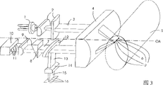
Fig. 3 is the synoptic diagram of an advantageous forms of implementation of apparatus of the present invention, and it has the attachment device that is used for determining intensity of reflected light.
Fig. 4 is the synoptic diagram of a favourable replacement form of implementation of apparatus of the present invention, and it has the classification transmissive optical element that depends on the locus.
Fig. 5 is a synoptic diagram of replacing the light path of form of implementation through apparatus of the present invention, and it has parallel (Kollimiert) illumination beam of an oblique incidence.
Fig. 6 is the synoptic diagram that produces light pad (Lichtteppich) as Reflect light line ground on forme.
Fig. 7 is the synoptic diagram that explanation positional information in apparatus of the present invention is converted into strength information.
Fig. 8 be one of apparatus of the present invention replace in the form of implementation and be positioned at the light pad after the synoptic diagram of light path of projection lens's group part.
Fig. 9 is the synoptic diagram of the first favourable improvement project of the replacement form of implementation of apparatus of the present invention.
Figure 10 is the synoptic diagram of the second favourable improvement project of the replacement form of implementation of apparatus of the present invention.
Embodiment
Fig. 1 represents an advantageous forms of implementation of apparatus of the present invention with the light path synoptic diagram.In preferred implementing form, light source 1 is a diode laser.The non-spherical optical elements of the light that sends by laser instrument by preferably having non-rotating symmetry, be converted into laser beam 3 as first projection lens's group 2 of cylindrical lens, it by unshowned imaging device (Bebilderungseinrichtung), generally is n the record surface that (here being 4) image point limits of diode laser array that its width has covered, and so select its height, promptly light beam is negligible along dispersing of the direction of propagation.Laser beam accumulates on the forme 5 from axle by objective lens (here being cylindrical lens 4) (off-axis), thus on forme projection a narrow light pad 6.Figure 1 illustrates a plane forme, but it can be the forme with macrobending surface usually without restriction, this bending is negligible on microcosmic or part concerning the projection of apparatus of the present invention.The laser bias of a point is the range deviation on relative datum plane especially.The width that n the image point by imaging device of record surface determined on light pad 6 width and the forme 5 is identical.Light by forme 5 reflections is become directional light and is converted to laser beam 7 by objective lens 4.Laser beam 7 shine one have on the radioparent optical element that depends on the position, preferably on grey wedge 8, grey wedge 8 and distance dependent ground transmission apart from optical projection system optical axis OA, and general in-plant transmission is greater than remote transmission.For this optical element, the refraction when light is injected and penetrated is negligible.Transmission and in case of necessity the light that also weakens of its intensity focus on the photosensitive detector 10 by a focus lamp group (here being cylindrical lens) 9.In preferred implementing form, photosensitive detector has n photodiode 11.
Under the device duty, the light pad 6 on the forme 5 also can be positioned on the separated by spaces position of n image point of imaging device light source.Therefore, forme 5 can relatively move, thus the face below that a point of its face at first falls into the light pad 6 of the size with the face that is limited by n image point and falls imaging device n image point P subsequently.Because translation or rotational parameters are known, so can extrapolate the actual range that exists when the imaging according to above-mentioned measurement.
Geometric configuration shown in Figure 1 is a preferred implementing form of the present invention.Also can be susceptible to following structure, promptly especially can advantageously add other optical element and carry out beam-shaping.Here, reflective optical devices proves suitable.
Fig. 2 is how explanation forme position deviation and the reflection spot position deviation that therefore forms cause different light paths by apparatus of the present invention a synoptic diagram.For the purpose of simplifying discussion, the sagittal cross section through apparatus of the present invention of not drawn exactly perpendicular to the straight line that is limited by optical cross-section 6 with having general limitation.Light beam 21 is parallel to the irradiation of optical axis 22 ground from the left side.It is reflected to optical axis 22 by scioptics 23.As working point or reference position be provided with the intersection point on plane 25 of band optical axis 22.In the ordinary course of things, if light beam 21 has different semiaxis on meridian direction and sagittal direction, light pad 24 has appearred on plane 25 then.Light by plane 25 reflections is converted to light beam 26 by lens 23 again, and described parallel beam is propagated in optical axis 22 ground.Light beam 21 by lens 23 refractions intersects with the plane 27 in the light pad 28, and this plane 27 is between lens 23 and reference field 25.Light scioptics 23 by 28 reflections of light pad are converted into light beam 29, and it is propagated abreast along optical axis 22.The distance of light beam 29 and optical axis is less than the distance of light beam 26.One intersects further from the plane 210 of lens 23 and the light beam that is refracted on lens 23 21 in the light pad 211 than plane 25, is converted into light beam 212 from the light scioptics 23 of light pad 211, this parallel beam in optical axis 22 ground along propagation.The distance of light beam 212 and optical axis is greater than the distance of light beam 26 with optical axis.As shown in Figure 2, in such configuration, this position, promptly with the distance on plane, reference field 25 front and back with apart from the distance of optical axis 22 relation on the function (funktionell) is arranged from the parallel beam of projection lens's group, wherein the light by plane reflection is converted into described parallel beam.In other words, plane 27 or 210 positional informations apart from reference field 25 are converted into the routing information of the distance of parallel beam 26,29 and 212.This routing information can depend on the light intensity that is encoded as light beam 26,29 and 212 apart from the optical element 213 of optical axis 22 distance ground transmissions by one.For example after process had the radioparent optical element 213 that depends on the position, light beam 214 advantageously had the intensity less than light beam 215, and light beam 215 has the intensity less than light beam 216.In other words, parallel beam is converted into strength information apart from the contained routing information in the position of optical axis, thereby light beam 214,215 and 216 can be projected onto on the unshowned detecting device by unshowned projection lens group, has wherein still obtained the information relevant with plane of reflection position.
By the preferred implementing form of apparatus of the present invention shown in Figure 1, realized being converted into the intensity of all n some P simultaneously in conjunction with the described path position information of Fig. 2.For this reason, the optical projection system of Fig. 1 (Abbildungssystem) can be projection lens's group, and it has produced a light pad 6 on forme 5, and described light pad has different semiaxis on sagittal direction and meridian direction.In addition, the face of light pad 6 has covered definite face by n image point P of imaging device.Light by optical cross-section 6 reflection is projected on the detecting device face 10 by projection lens's group, the each several part of this face respectively with n photodiode 11 in one match.In other words, on detecting device, the perspective view of optical cross-section 6 is divided into n part at least, thereby two points in the n point is respectively arranged are distinguishing between wherein each zone.Here, each part matches with one of n image point P of imaging device light source clearly.Aspect the time basically, especially in detecting device action parameter characteristic range by detecting device simultaneously or produce signal concurrently, wherein each signal in n signal one of is put corresponding with n clearly.If optical cross-section 6 parts have different distances apart from projection lens's group 4, in other words, the reflection occur in such plane, promptly its position deviation the position of reference plane, in apparatus of the present invention, this part respective intensities information relevant with function is matched.So, can realize parallel processing type optical range finder.
The drawn favourable expanded configuration of apparatus of the present invention of Fig. 3.In Fig. 3, schematically show apparatus of the present invention with additional optics, they are used for determining by the forme intensity of light reflected.Fig. 3 at first shows the element 1-11 described in Fig. 1.In addition, in the light path of laser beam 7, added an optical splitter 12, by one light beam 13 of optical splitter output coupling.This light beam is projected on another photosensitive detector 15 by cylindrical lens 14.Photosensitive detector 15 has n photodiode 16.Optical splitter 12 can have any known transmitted light and the division factor between the reflected light (Teilungsverhaeltnis).An important point in this configuration is, with forme 5 apart from the position of objective lens 4 and thereby with the folded light beam that causes of optical cross-section 6 the location independent ground of different light paths is arranged, can determine intensity of reflected light, be the intensity of light beam 7 according to the division factor of optical splitter 12 and known intensity from light source 1 light.By the strength signal ratio of corresponding photodiode 11,16, can produce a conditioning signal that has nothing to do with especially relevant existing folded light beam power by photosensitive detector 10 signals with the actual light power of light source 1.
Fig. 4 schematically shows a replacement form of implementation of apparatus of the present invention, and it has depends on the optical element of spatial axes apart from ground classification transmission.0 and 1 classification transmission is particularly advantageous.In order to utilize such transmission, so propagate light beam 7, promptly when on the reference position on forme 5 optical cross-sections 6 reflex time, half light beam finishes to propagate by transmission level 0.The position deviation of the plane of reflection as being converted into the positional information of reflection of parallel beam with describing.According to the distance of reflection of parallel beam apart from optical axis OA, more or less some is by transmission level 0 and from the intrafascicular disappearance of overall optical.So, strength information has stayed vestige in light beam.Boundling is on detecting device in other words because whole transmitted light is incident upon, and under the situation of polymerization light, the intensity modulated of polymerization effect such as edge diffraction, the tired Nellie integration of husband is negligible.
Whether have the classification transmissison characteristic or the transmissison characteristic that in little space region, changes (as blade (Messerschneide) or single face coating mirror) or comprise the grey wedge that has wide zone of transition according to the optical element that depends on the classification transmission of position ground, can select to shine the optical cross-section height of forme with the narrow zone of transition between transmission and non-projection unit are divided.Under the situation of blade, optical cross-section is should be so high, i.e. blade also optical cross-section figure in the division detector plane when the forme maximum deflection, i.e. transmission 1%-99% always.Under the situation of grey wedge, illumination beam has very little height, thus the overall optical cross section always penetrate by grey wedge, its position can as far as possible accurately be determined by gray-scale value.
As light source 1 ground, can adopt any laser instrument, in preferred implementing form, it can be diode laser or solid state laser.Perhaps, can adopt and send the not light source of polymerization light.Forme is the good reflection light beam wavelength advantageously.In preferred implementing form, wavelength is positioned at red spectral region, for example 670nm.Usually, under the persistent oscillation state, use laser instrument.But in order to improve the insensitiveness to other undesirable reflection, pulsing operation is favourable.
Shown in the figure open up to mend learn and the geometric configuration of projection lens's group can wait additionally by other optical element such as spherical and non-spherical lens, anamorphote, mirror, carry out the favourable beam-forming of light beam 3 or light beam 7.
In a favourable improvement configuration of the present invention, conditioning signal is broken down into mean value, and it is calculated by the intensity sum that records on n photodiode.Mean value is used as the general regulated value of imaging device focal line motion.Difference between each photodiode conditioning signal and the mean value has played the effect of the conditioning signal of each laser instrument that is used for the imaging device laser array.
Replace in the form of implementation at another, the quantity of the photodiode in the photosensitive detector is less than the laser beam quantity of imaging device.In this case, the conditioning signal that produces by the intensity that is radiated on definite photodiode as conditioning signal be used to a plurality of laser beams arranged side by side.If the photodiode quantity in the photosensitive detector greater than the quantity of imaging device laser beam, then for example can use the mean value of a plurality of conditioning signals of adjacent photodiode to be used for a laser beam.The figure of above-mentioned optical cross-section divide also can less than or greater than by the predetermined quantity of the quantity of light source n of operating means.
In a favourable improvement project of the present invention, adopted micro optical element.For example, focal circle cylindrical lens 9 and 14 can be constituted and can be had the lens of an array by a plurality of optical elements.
Inject in apparatus of the present invention photosensitive detector for fear of the laser beam of imaging device, be provided with a corresponding optical band pass filter, its transmission is used for producing at parallel processing type optical range finder the wavelength of the light source 1 of reflection spot.Replace in the form of implementation at one of the present invention, it is the photosensitive detector with photoelectric cell, photomultiplier cell or charge-coupled display (CCD).
The imaging device that such apparatus of the present invention can be configured to forme is what to separate, perhaps completely or partially integrates with imaging device.In other words, can jointly use the parts of apparatus of the present invention and imaging device projection lens group.
In Fig. 5, schematically show a light path of replacing form of implementation through apparatus of the present invention.The figure coordinate x of coordinate system 502, y, z be the position of expression cylinder 504 in so-called drum type printing plate exposure device or direct imaging formula printing machine for example.Here, rotation 505 is positioned at x upwards, and z is to being determined by optical axis, be placed in forme 510 on the cylinder 504 from the light of imaging device light source 522 along the optical axis directive on, y is to expression the 3rd direction in space, it perpendicular to x, z to.Illumination beam 506 normally light source 508 is projected onto on the forme 510 by the mirror group 507 of cylinder symmetric as the collimated light beam of laser instrument.Being projected in of illumination beam 506 formed a light pad 509 on the forme 510.Preferably a rectangle and the zone that evenly illuminated as far as possible of light pad 509, its width equals to want the width of surveyed area.Preferably illumination beam 506 is with miter angle directive forme 510 and perpendicular to the reflection of incident direction ground.Light pad 509 is projected onto in the conversion plane 514 by intermediate mirror group 511.One has the radioparent optical element that depends on the position and is positioned at this conversion plane 514.It has realized focusing on photosensitive detector 520 by another projection lens's group 519.In addition, in a favourable improvement configuration, as illustrated in fig. 5, an optical splitter 512 is installed in light path before the conversion plane 514.On identical light path 516, the coupling of the part of described light is outputed on the photosensitive detector 518 by projection lens's group 517.
Fig. 6 with schematic view illustrating how on forme, produce the light pad and how to convert positional information to catoptrical routing information as reflected ray ground.Fig. 6 represents an illumination beam 601, it at this for example with forme of miter angle directive and be substantially perpendicular to incident direction ground reflection.This forme can have diverse location at z on (normal direction 603).On forme 608 primary importances, produce first intersection 602, on the forme second place 609, produced second intersection 604, on forme 608 the 3rd position, produced the 3rd intersection 606.For example, such situation of in Fig. 6, having drawn, wherein forme 608 is positioned at such position, and promptly illumination beam 601 is being reflected as light beam 612 in intersection 604 on this position.If there is not forme 608, then light beam may continue to propagate with illumination beam 605 forms.Three intersections 602,604 and 606 that draw for example are positioned at a line plane 610.In other words, if forme 608 changed its at z to being position on the normal direction 603, then intersection 602,604 or 606 possible position have formed the plane in the space, this plane by illumination beam inject direction and wherein intersection determine as second intersection 604.
The situation that positional information is converted to strength information in device of the present invention is described in conjunction with Fig. 7 and with synoptic diagram.Fig. 7 represents schematically how optical cross-section 702 is positioned on the forme 701.By reflection conversion indicated by the arrow, the position of optical cross-section 702 is converted into the routing information of the folded light beam 704 in the online plane 705.Projection converter 706 arrives this information translation in the conversion plane 707 as resembling spot 708.Conversion plane 707 has the radioparent optical element 709 that depends on the position.It so influences strength information 710, promptly measures a definite light intensity in the detection plane 711 on the photodiode 713 of a light-sensitive detector 712.In order to produce luminance signal 715, depend on each photodiode 713 measurement produced signal converter 714.Therefore, as function of position produced and be used for each regional signal 716 in the optical cross-section.Information in the luminance signal 715 can be passed to such device by serial or parallel ground as conditioning signal subsequently, and this device is complementary the optical parametric of imaging beam and the unevenness of forme.
Fig. 8 shows the synoptic diagram of the light path in the form of implementation of the projection lens group part after being located at the light pad.In component 8a, a cross section in the yz plane of having drawn, and in component 8b, the cross section of having drawn along the x coordinate.In component 8a, the forme primary importance 801 of having drawn and the forme second place 803 and a line plane 802, they have two intersection points, i.e. first reflection spot 812 and second reflection spot 814.By a rotational symmetric projection lens group 804 and spherical lens preferably, first reflection spot 812 and second reflection spot 814 are projected in the conversion plane 806.One has the radioparent optical element that depends on the position and is positioned at this conversion plane 806.Begin therefrom, realized projecting on the photosensitive detector 810, be equipped with first sensing point 816 wherein for first reflection spot 812, disposed the 3rd sensing point 820 for second reflection spot 814 by another rotational symmetric projection lens group.Alternatively, component 8b has drawn along x coordinate cross section and has had the situation of first sensing point 816 and second sensing point 818.
Fig. 9 apparatus of the present invention of having drawn are replaced the synoptic diagram of the first favourable improvement project of form of implementation.In component 9b, drawn along the situation in the cross section of x axle in the component 9a cross section in the yz plane of having drawn.On primary importance 901, intersect with a line plane 902 on first reflection spot 914 on the surface of forme, and intersect with line plane 902 on second reflection spot 916 on the surface of forme on the second place 903.First reflection spot 914 and second reflection spot 916 are projected onto by bipartite at least projection lens group (it is made of projection lens's group 904 of first cylinder symmetric and projection lens's group 908 of second cylinder symmetric) to have on the radioparent optical element position conversion plane 910 thereon that depends on the position.At this, projection lens's group 904 of first cylinder symmetric and projection lens's group 908 of second cylinder symmetric have the axis of symmetry, and they roughly are orthogonal.Projection lens's group 912, the first reflection spots 914 by three cylindrical shape symmetry are projected onto on first sensing point 918, and second reflection spot 916 is projected onto on second sensing point 920, and in the component 9a of Fig. 9, these 2 a little points overlap.How separated the component 9b of Fig. 9 is by the projection of having expressed along the sectional view of x direction on x direction and yz direction.On this direction from the light beam of first reflection spot 914 be subjected to first cylinder symmetric projection lens's group 904 influence and be projected onto in first sensing point 918.Correspondingly, the light that comes from second reflection spot 916 is projected onto on second sensing point 920 by projection lens's group 904 of first cylinder symmetric.
Figure 10 is the synoptic diagram that apparatus of the present invention are replaced the second favourable improved procedure of form of implementation.In the component 10a of Figure 10, drawn a cross section in the yz plane, and in the component 10b of Figure 10, drawn an x to the cross section.On primary importance 1001, intersect on first reflection spot 1014 and line plane 1002 on the forme surface, and on the second place 1003, intersect with line plane 1002 on second reflection spot 1016 on the surface of forme.First reflection spot 1014 and second reflection spot 1016 are projected onto on the conversion plane 1006 by a rotational symmetric projection lens group 1004.One has the radioparent optical element that depends on the position and is positioned at this plane.Begin therefrom, utilize projection lens's group (it is made of projection lens's group 1008 of one first cylinder symmetric and projection lens's group 1010 of one second cylinder symmetric, and the axis of symmetry of these projection lens's groups is roughly vertical mutually) to be projected onto on the detection plane 1012 with at least two parts.Coincide with in this plane corresponding to first sensing point 1018 of first reflection spot 104 with corresponding to second sensing point 1020 of second reflection spot 1016.In the component 10b of Figure 10, illustrated along quadrature, be the cross section of x direction.First reflection spot 1014 and second reflection spot 1016 are projected onto in the conversion plane 1006 by rotational symmetric projection lens group 1004.Begin therefrom, projection lens's group 1008 of first cylinder symmetric causes first reflection spot 1014 to be projected onto on first sensing point 1018 and second reflection spot 1016 is projected onto on second sensing point 1020.
Such apparatus of the present invention not only can be used in printing plate exposure device but also can be used in printing equipment or the printing machine, in especially direct imaging formula printing equipment or the printing machine.
Description of reference numerals
The P-point; The OA-optical axis; The 1-light source; 2-projection mirror group; The 3-laser beam; The 4-objective lens; The 5-forme; 6-light pad; The 7-laser beam; 8-has the radioparent element that depends on the position; The cylindrical lens of 9-; The photosensitive detector of 10-; The 11-photodiode; 12-light splitting device; 13-Light beam; The cylindrical lens of 14-; The photosensitive detector of 15-; The 16-photodiode; The 21-light beam; The 22-optical axis; The 23-lens; 24-light pad; 25-benchmark face; The 26-light beam; The 27-plane; 28-The light pad; The 29-light beam; The 210-plane; 211-light pad; The 212-light beam; 213-has and depends on The radioparent optics element of position; The 214-light beam; The 215-light beam; The 216-light beam; 502-Coordinate system; The 504-cylinder; The 505-rotation; 506-shines light beam; 507-is cylindrical right The mirror group that claims; The 508-light source; 509-light pad; The 510-forme; 512-light splitting device; Among the 511-Between the mirror group; The 514-conversion plane; The 516-same optical path; 517-projection mirror group; 518-is photosensitive Detector; 519-projection mirror group; The photosensitive detector of 520-; The 522-imaging source; 524-throws Shadow mirror group; 601-shines light source; 602-hands over the line primary importance; 603-normal direction; 604-Hand over the line second place; The continuity of 605-irradiation light beam; 606-hands over line the 3rd position; The 608-seal Version; 610-line plane; 612-reflects light beam; The 701-forme; The 702-optical cross-section; 703-is anti-Penetrate conversion; Path information in the 704-reflection light beam; 705-line plane; 706-projection conversion; The 707-conversion plane; 708-resembles spot; 709-has the radioparent optics unit of depending on the position Part; The 710-strength information; The 711-detection plane; The photosensitive detector of 712-; 713-photoelectricity two Utmost point pipe; The conversion of 714-signal; The 715-luminance signal; 716-each point signal; 801-forme One position; 802-line plane; The 803-forme second place; The symmetrical projection mirror of 804-rotation Group; The 806-conversion plane; The symmetrical projection mirror group of 808-rotation; The photosensitive detector of 810-; The 812-first reflection point; The 814-second reflection point; 816-first sensing point; 818-second visits Measuring point; 820-the 3rd sensing point; 901-forme primary importance; 902-line plane; The 903-seal The version second place; The projection mirror group of 904-first cylinder symmetric; The 906-detection plane; 908-The projection mirror group of second cylinder symmetric; The 910-conversion plane; 912-three cylindrical shape symmetry Projection mirror group; The 914-first reflection point; The 916-second reflection point; 918-first sensing point; 920-second sensing point; 1001-forme primary importance; 1002-line plane; 1003-forme Two positions; The projection mirror group of 1004-rotation-symmetric; The 1006-conversion plane; 1008-first circle The projection mirror group of cylindrical symmetry; The projection mirror group of 1010-second cylinder symmetric; 1012-visits Lining face; The 1014-first reflection point; The 1016-second reflection point; 1018-first sensing point; 1020-second sensing point.
Claims (20)
1. the device of the deviation of the individual discrete reference position of a position of measuring n point (P) and its n, wherein n is the natural number more than or equal to 2, described device has an electromagnetic radiation source (1), projection lens's group (2,4,9), electromagnetic radiation forms a light pad (6) through this projection lens's group a part of the time thus, this light pad is incident upon on the position of all n points (P) with being tilted, make this light pad (6) irradiation by defined of this n point (P), wherein n the point at least one, the position on this face and the deviation of its reference position have caused by the light of this face reflection by projection lens's group with relation one to one, with by the described point (P) on the reference position another different light path of catoptrical light path, make the positional information of this n point (P) be converted into the routing information of electromagnetic radiation by this projection lens's group; Described device also has a photosensitive detector (10), this light that is reflected of an element (9) by this projection lens's group is focused on this photosensitive detector, it is characterized in that, this photosensitive detector side by side or concurrently produces n signal in time, wherein, in this n signal each by correspondingly with this n point (P) in one match, be provided with at least one other element (8) of this projection lens's group, this element is set at this focusing in light path element (9) before, and have the transmittance relevant with the position, make the routing information of light be converted into intensity information by this projection lens's group.
2. device as claimed in claim 1 is characterized in that, described source (1) is an independent radiation source.
3. device as claimed in claim 1 or 2 is characterized in that, this n o'clock in a plane or point-blank.
4. device as claimed in claim 1 or 2 is characterized in that, this projection lens's group (2,4,9) has non-spherical optical elements.
5. device as claimed in claim 1 or 2 is characterized in that, photosensitive detector (10) is made of a plurality of separate light activated elements.
6. device as claimed in claim 5 is characterized in that, light activated element (11) is photodiode, photoelectric cell, photomultiplier cell or charge-coupled display.
7. device as claimed in claim 5 is characterized in that, at least two light activated elements in the separate light activated element (11) of n have disposed during n is put at least two just and correspondingly.
8. device as claimed in claim 1 or 2 is characterized in that, radiation source (1) is launched at least a infrared ray or wavelength of visible light.
9. device as claimed in claim 1 is characterized in that, described other element (8) is a grey wedge or a seamed edge.
10. device as claimed in claim 1 or 2 is characterized in that, the light pad part afterwards that is arranged on of projection lens's group has at least two optical elements (904,908) with axis of symmetry of mutually orthogonal cylinder symmetric.
11. device as claimed in claim 1 or 2 is characterized in that, has produced an intermediate image in a conversion plane (1006), described have the radioparent optical element (8) relevant with the position and be in this conversion plane.
12. device as claimed in claim 1 or 2 is characterized in that, has at least one optical splitter (12) in the light path of projection lens's group after reflection.
13. device as claimed in claim 12 is characterized in that, is provided with at least that another has the photosensitive detector of a plurality of independently light activated elements, wherein, each of separate element to should n point (P) at least one or just what a.
14. a stadimeter is characterized in that described stadimeter has device as claimed in claim 1 or 2.
15. one kind has laser instrument that n can independently control and the separate projection lens's group and the imaging device of an autofocus system, this focusing system can be carried out focus shift at least two in n the laser instrument that can independently control with being independent of each other, wherein n is a natural number, it is characterized in that autofocus system is regulated according to the measurement result of stadimeter as described in claim 14.
16. a printing plate exposure device is characterized in that, printing plate exposure device has at least one imaging device as claimed in claim 15.
17. a printing equipment is characterized in that, described printing equipment has an imaging device as claimed in claim 15.
18. a printing machine is characterized in that, it has at least one printing equipment as claimed in claim 17.
19. the method for the position of a definite n point (P) and the deviation of its n reference position, wherein n is the natural number more than or equal to 2, and this method may further comprise the steps:
-electromagnetic radiation is projected on each single point of n the point (P) in the light pad (6);
-positional information of these points (P) is converted to the routing information of light beam;
-survey the reflected light of at least two points in this n the point (P) discriminatively;
Wherein, side by side or concurrently carry out the said method step in time for all n point (P),
It is characterized in that,, be converted to strength information by having the routing information of the radioparent element (8) relevant with light with the position for positional information is converted to strength information.
20. the method for measuring the deviation of n position of putting and its reference position as claimed in claim 19, it also has following additional step, be the instantaneous strength of the electromagnetic radiation of at least one the point measurement reflection in the n point, it is characterized in that, carry out the comparison of instantaneous strength of the electromagnetic radiation of the intensity of reflected light on the corresponding light activated element of detecting device, measured and reflection.
Applications Claiming Priority (4)
| Application Number | Priority Date | Filing Date | Title |
|---|---|---|---|
| DE10044082 | 2000-09-07 | ||
| DE10111245A DE10111245A1 (en) | 2000-09-07 | 2001-03-09 | Parallel optical rangefinder |
| DE10111245.9 | 2001-03-09 | ||
| DE10044082.7 | 2001-03-09 |
Publications (2)
| Publication Number | Publication Date |
|---|---|
| CN1342921A CN1342921A (en) | 2002-04-03 |
| CN1262885C true CN1262885C (en) | 2006-07-05 |
Family
ID=26006951
Family Applications (1)
| Application Number | Title | Priority Date | Filing Date |
|---|---|---|---|
| CNB011420472A Expired - Fee Related CN1262885C (en) | 2000-09-07 | 2001-09-07 | Parallel processing type optical range finder |
Country Status (9)
| Country | Link |
|---|---|
| US (1) | US6661446B2 (en) |
| EP (1) | EP1186928B1 (en) |
| JP (1) | JP4884615B2 (en) |
| CN (1) | CN1262885C (en) |
| AT (1) | ATE316254T1 (en) |
| CA (1) | CA2355000A1 (en) |
| CZ (1) | CZ20012830A3 (en) |
| DE (1) | DE50108728D1 (en) |
| HK (1) | HK1045881A1 (en) |
Families Citing this family (13)
| Publication number | Priority date | Publication date | Assignee | Title |
|---|---|---|---|---|
| US7253929B2 (en) * | 2002-02-06 | 2007-08-07 | Quad/Tech, Inc. | Camera assembly for a printing press |
| EP1649256B1 (en) * | 2003-07-30 | 2010-01-20 | Optris GmbH | Device for non-contact temperature measurement |
| DE102004014048B4 (en) * | 2004-03-19 | 2008-10-30 | Sirona Dental Systems Gmbh | Measuring device and method according to the basic principle of confocal microscopy |
| JP4652745B2 (en) * | 2004-08-19 | 2011-03-16 | 株式会社ミツトヨ | Optical displacement measuring instrument |
| US20070244753A1 (en) * | 2005-08-26 | 2007-10-18 | Spot Runner, Inc., A Delaware Corporation, Small Business Concern | Systems and Methods For Media Planning, Ad Production, and Ad Placement For Print |
| JP4773329B2 (en) * | 2005-12-22 | 2011-09-14 | パナソニック株式会社 | Interface position measuring method and measuring apparatus, layer thickness measuring method and measuring apparatus, and optical disc manufacturing method and manufacturing apparatus |
| US8240912B2 (en) * | 2008-08-15 | 2012-08-14 | Fluke Corporation | Multi-zone non-contact spot thermometer |
| JP5121771B2 (en) * | 2008-09-19 | 2013-01-16 | 三菱電機株式会社 | Light source unit and image display device |
| RU2516165C1 (en) * | 2012-06-09 | 2014-05-20 | Федеральное государственное унитарное предприятие "Научно-исследовательский институт "Полюс" им. М.Ф. Стельмаха" | Laser range finder |
| KR101538319B1 (en) * | 2013-12-24 | 2015-07-23 | 에이옵틱스주식회사 | Three- dimensional shape measuring apparatus and measuring method using the same |
| CN103883535A (en) * | 2014-04-15 | 2014-06-25 | 钟灵宪 | Water pump controller |
| CN104714289B (en) * | 2014-12-31 | 2017-12-15 | 武汉华工激光工程有限责任公司 | A kind of automatic focusing mechanism of light path amplification |
| CN108872615B (en) * | 2018-04-26 | 2021-08-06 | 迪瑞医疗科技股份有限公司 | Coupling type blood coagulation testing system and method |
Family Cites Families (18)
| Publication number | Priority date | Publication date | Assignee | Title |
|---|---|---|---|---|
| JPS5870434A (en) | 1981-10-22 | 1983-04-26 | Toshiba Corp | Optical head |
| US4705401A (en) * | 1985-08-12 | 1987-11-10 | Cyberware Laboratory Inc. | Rapid three-dimensional surface digitizer |
| JPH07105327B2 (en) * | 1986-06-27 | 1995-11-13 | キヤノン株式会社 | Surface position detector |
| DE4013283C1 (en) * | 1990-04-26 | 1991-10-02 | Hans Dr. 8032 Graefelfing De Langer | Scanning surface by projecting modulation pattern - observing surface by optics via second modulation pattern at angle to direction of projection |
| US5248992A (en) * | 1991-08-23 | 1993-09-28 | Eastman Kodak Company | High numerical aperture image forming apparatus using optical fibers for both writing and focus control |
| US5365535A (en) * | 1992-01-13 | 1994-11-15 | Canon Kabushiki Kaisha | Semiconductor laser and beam splitting devices, and optical information recording/reproducing, optical communication, and optomagnetic recording/reproducing apparatuses using semiconductor laser and beam splitting devices |
| JP2987007B2 (en) * | 1992-05-28 | 1999-12-06 | 日立電子エンジニアリング株式会社 | Foreign matter detection optical system of color filter |
| JPH06102025A (en) * | 1992-09-18 | 1994-04-12 | Ricoh Co Ltd | Optical displacement gauge |
| US5302997A (en) | 1992-12-28 | 1994-04-12 | Eastman Kodak Company | Composite photometric and range finding element array |
| JP3409917B2 (en) * | 1994-04-04 | 2003-05-26 | 株式会社ミツトヨ | Method and apparatus for measuring thickness of transparent body |
| JP3555230B2 (en) * | 1994-05-18 | 2004-08-18 | 株式会社ニコン | Projection exposure equipment |
| JP3319666B2 (en) * | 1994-11-24 | 2002-09-03 | 株式会社ミツトヨ | Edge detection device |
| US5675407A (en) * | 1995-03-02 | 1997-10-07 | Zheng Jason Geng | Color ranging method for high speed low-cost three dimensional surface profile measurement |
| US5764272A (en) * | 1995-09-12 | 1998-06-09 | Eastman Kodak Company | Autofocus mechanism for laser imager |
| JP3050102B2 (en) * | 1995-09-29 | 2000-06-12 | 富士ゼロックス株式会社 | Light beam focal position detection device, light beam irradiation device, and light beam recording device |
| JPH09236408A (en) * | 1996-02-28 | 1997-09-09 | Nikon Corp | Focal position detecting device |
| US6046812A (en) * | 1997-05-29 | 2000-04-04 | Korea Atomic Energy Research Institute | Shape-measuring laser apparatus using anisotropic magnification optics |
| JP3688185B2 (en) * | 2000-05-08 | 2005-08-24 | 株式会社東京精密 | Focus detection device and autofocus microscope |
-
2001
- 2001-08-01 AT AT01117770T patent/ATE316254T1/en not_active IP Right Cessation
- 2001-08-01 EP EP01117770A patent/EP1186928B1/en not_active Expired - Lifetime
- 2001-08-01 DE DE50108728T patent/DE50108728D1/en not_active Expired - Lifetime
- 2001-08-03 CZ CZ20012830A patent/CZ20012830A3/en unknown
- 2001-08-10 CA CA002355000A patent/CA2355000A1/en not_active Abandoned
- 2001-09-04 US US09/946,708 patent/US6661446B2/en not_active Expired - Fee Related
- 2001-09-07 JP JP2001271793A patent/JP4884615B2/en not_active Expired - Fee Related
- 2001-09-07 CN CNB011420472A patent/CN1262885C/en not_active Expired - Fee Related
-
2002
- 2002-10-02 HK HK02107237A patent/HK1045881A1/en not_active IP Right Cessation
Also Published As
| Publication number | Publication date |
|---|---|
| EP1186928B1 (en) | 2006-01-18 |
| CN1342921A (en) | 2002-04-03 |
| HK1045881A1 (en) | 2002-12-13 |
| EP1186928A2 (en) | 2002-03-13 |
| DE50108728D1 (en) | 2006-04-06 |
| US6661446B2 (en) | 2003-12-09 |
| ATE316254T1 (en) | 2006-02-15 |
| CZ20012830A3 (en) | 2002-04-17 |
| US20020027594A1 (en) | 2002-03-07 |
| JP4884615B2 (en) | 2012-02-29 |
| CA2355000A1 (en) | 2002-03-07 |
| EP1186928A3 (en) | 2004-04-28 |
| JP2002188903A (en) | 2002-07-05 |
Similar Documents
| Publication | Publication Date | Title |
|---|---|---|
| CN1262885C (en) | Parallel processing type optical range finder | |
| US6862097B2 (en) | Three-dimensional shape measuring method, and three-dimensional shape measuring apparatus | |
| CN100592214C (en) | Device and method for focusing and leveling based on microlens array | |
| KR20040018327A (en) | Image display system | |
| CA2057084C (en) | Light irradiating apparatus having light emitting diode used as light source | |
| EP0768542B1 (en) | Optical distance measuring apparatus | |
| JPH0762614B2 (en) | Optical sensor | |
| AU2003286237B2 (en) | Structured light projector | |
| JP2862311B2 (en) | Surface position detection device | |
| US5109161A (en) | Light emitter and optical system for a distance measuring device | |
| JPH10239051A (en) | Tilt angle measuring device | |
| US4880310A (en) | Optical device for alignment in a projection exposure apparatus | |
| CN102043352B (en) | Focusing and leveling detection device | |
| CN111610534B (en) | Image forming apparatus and image forming method | |
| US4611122A (en) | Signal detection apparatus with plural elongate beams corresponding | |
| JPH0153767B2 (en) | ||
| JPH09203631A (en) | Distance-measuring sensor | |
| JPWO2019163210A1 (en) | Scanning optics and rider | |
| JP7304970B2 (en) | Surface detection device and method | |
| CN111090223B (en) | Optical measurement system | |
| EP3998424B1 (en) | Pbs beam splitter-based headlamp unit | |
| JPS60149985A (en) | Optical distance measuring apparatus | |
| CN211452246U (en) | Structured light inclined projection device for three-dimensional measurement | |
| JP2620143B2 (en) | Distance measurement mechanism of autofocus device | |
| JP3222295B2 (en) | Optical displacement sensor |
Legal Events
| Date | Code | Title | Description |
|---|---|---|---|
| C06 | Publication | ||
| PB01 | Publication | ||
| C10 | Entry into substantive examination | ||
| SE01 | Entry into force of request for substantive examination | ||
| C14 | Grant of patent or utility model | ||
| GR01 | Patent grant | ||
| C17 | Cessation of patent right | ||
| CF01 | Termination of patent right due to non-payment of annual fee |
Granted publication date: 20060705 Termination date: 20130907 |