CN1262315C - Modular gas-pressured needled-less injector - Google Patents
Modular gas-pressured needled-less injector Download PDFInfo
- Publication number
- CN1262315C CN1262315C CN01823321.XA CN01823321A CN1262315C CN 1262315 C CN1262315 C CN 1262315C CN 01823321 A CN01823321 A CN 01823321A CN 1262315 C CN1262315 C CN 1262315C
- Authority
- CN
- China
- Prior art keywords
- needleless injector
- shell
- injector according
- valve
- trigger
- Prior art date
- Legal status (The legal status is an assumption and is not a legal conclusion. Google has not performed a legal analysis and makes no representation as to the accuracy of the status listed.)
- Expired - Fee Related
Links
Images


Classifications
-
- A—HUMAN NECESSITIES
- A61—MEDICAL OR VETERINARY SCIENCE; HYGIENE
- A61M—DEVICES FOR INTRODUCING MEDIA INTO, OR ONTO, THE BODY; DEVICES FOR TRANSDUCING BODY MEDIA OR FOR TAKING MEDIA FROM THE BODY; DEVICES FOR PRODUCING OR ENDING SLEEP OR STUPOR
- A61M5/00—Devices for bringing media into the body in a subcutaneous, intra-vascular or intramuscular way; Accessories therefor, e.g. filling or cleaning devices, arm-rests
- A61M5/178—Syringes
- A61M5/30—Syringes for injection by jet action, without needle, e.g. for use with replaceable ampoules or carpules
-
- A—HUMAN NECESSITIES
- A61—MEDICAL OR VETERINARY SCIENCE; HYGIENE
- A61M—DEVICES FOR INTRODUCING MEDIA INTO, OR ONTO, THE BODY; DEVICES FOR TRANSDUCING BODY MEDIA OR FOR TAKING MEDIA FROM THE BODY; DEVICES FOR PRODUCING OR ENDING SLEEP OR STUPOR
- A61M5/00—Devices for bringing media into the body in a subcutaneous, intra-vascular or intramuscular way; Accessories therefor, e.g. filling or cleaning devices, arm-rests
- A61M5/178—Syringes
- A61M5/20—Automatic syringes, e.g. with automatically actuated piston rod, with automatic needle injection, filling automatically
- A61M2005/2073—Automatic syringes, e.g. with automatically actuated piston rod, with automatic needle injection, filling automatically preventing premature release, e.g. by making use of a safety lock
-
- A—HUMAN NECESSITIES
- A61—MEDICAL OR VETERINARY SCIENCE; HYGIENE
- A61M—DEVICES FOR INTRODUCING MEDIA INTO, OR ONTO, THE BODY; DEVICES FOR TRANSDUCING BODY MEDIA OR FOR TAKING MEDIA FROM THE BODY; DEVICES FOR PRODUCING OR ENDING SLEEP OR STUPOR
- A61M5/00—Devices for bringing media into the body in a subcutaneous, intra-vascular or intramuscular way; Accessories therefor, e.g. filling or cleaning devices, arm-rests
- A61M5/178—Syringes
- A61M5/31—Details
- A61M2005/3103—Leak prevention means for distal end of syringes, i.e. syringe end for mounting a needle
- A61M2005/3104—Caps for syringes without needle
-
- A—HUMAN NECESSITIES
- A61—MEDICAL OR VETERINARY SCIENCE; HYGIENE
- A61M—DEVICES FOR INTRODUCING MEDIA INTO, OR ONTO, THE BODY; DEVICES FOR TRANSDUCING BODY MEDIA OR FOR TAKING MEDIA FROM THE BODY; DEVICES FOR PRODUCING OR ENDING SLEEP OR STUPOR
- A61M5/00—Devices for bringing media into the body in a subcutaneous, intra-vascular or intramuscular way; Accessories therefor, e.g. filling or cleaning devices, arm-rests
- A61M5/178—Syringes
- A61M5/31—Details
- A61M2005/3123—Details having air entrapping or venting means, e.g. purging channels in pistons
-
- A—HUMAN NECESSITIES
- A61—MEDICAL OR VETERINARY SCIENCE; HYGIENE
- A61M—DEVICES FOR INTRODUCING MEDIA INTO, OR ONTO, THE BODY; DEVICES FOR TRANSDUCING BODY MEDIA OR FOR TAKING MEDIA FROM THE BODY; DEVICES FOR PRODUCING OR ENDING SLEEP OR STUPOR
- A61M5/00—Devices for bringing media into the body in a subcutaneous, intra-vascular or intramuscular way; Accessories therefor, e.g. filling or cleaning devices, arm-rests
- A61M5/178—Syringes
- A61M5/31—Details
- A61M5/315—Pistons; Piston-rods; Guiding, blocking or restricting the movement of the rod or piston; Appliances on the rod for facilitating dosing ; Dosing mechanisms
- A61M5/31511—Piston or piston-rod constructions, e.g. connection of piston with piston-rod
- A61M2005/31516—Piston or piston-rod constructions, e.g. connection of piston with piston-rod reducing dead-space in the syringe barrel after delivery
-
- A—HUMAN NECESSITIES
- A61—MEDICAL OR VETERINARY SCIENCE; HYGIENE
- A61M—DEVICES FOR INTRODUCING MEDIA INTO, OR ONTO, THE BODY; DEVICES FOR TRANSDUCING BODY MEDIA OR FOR TAKING MEDIA FROM THE BODY; DEVICES FOR PRODUCING OR ENDING SLEEP OR STUPOR
- A61M5/00—Devices for bringing media into the body in a subcutaneous, intra-vascular or intramuscular way; Accessories therefor, e.g. filling or cleaning devices, arm-rests
- A61M5/178—Syringes
- A61M5/20—Automatic syringes, e.g. with automatically actuated piston rod, with automatic needle injection, filling automatically
- A61M5/2053—Media being expelled from injector by pressurised fluid or vacuum
-
- A—HUMAN NECESSITIES
- A61—MEDICAL OR VETERINARY SCIENCE; HYGIENE
- A61M—DEVICES FOR INTRODUCING MEDIA INTO, OR ONTO, THE BODY; DEVICES FOR TRANSDUCING BODY MEDIA OR FOR TAKING MEDIA FROM THE BODY; DEVICES FOR PRODUCING OR ENDING SLEEP OR STUPOR
- A61M5/00—Devices for bringing media into the body in a subcutaneous, intra-vascular or intramuscular way; Accessories therefor, e.g. filling or cleaning devices, arm-rests
- A61M5/178—Syringes
- A61M5/30—Syringes for injection by jet action, without needle, e.g. for use with replaceable ampoules or carpules
- A61M5/3007—Syringes for injection by jet action, without needle, e.g. for use with replaceable ampoules or carpules with specially designed jet passages at the injector's distal end
-
- A—HUMAN NECESSITIES
- A61—MEDICAL OR VETERINARY SCIENCE; HYGIENE
- A61M—DEVICES FOR INTRODUCING MEDIA INTO, OR ONTO, THE BODY; DEVICES FOR TRANSDUCING BODY MEDIA OR FOR TAKING MEDIA FROM THE BODY; DEVICES FOR PRODUCING OR ENDING SLEEP OR STUPOR
- A61M5/00—Devices for bringing media into the body in a subcutaneous, intra-vascular or intramuscular way; Accessories therefor, e.g. filling or cleaning devices, arm-rests
- A61M5/178—Syringes
- A61M5/31—Details
- A61M5/3129—Syringe barrels
- A61M5/3137—Specially designed finger grip means, e.g. for easy manipulation of the syringe rod
-
- A—HUMAN NECESSITIES
- A61—MEDICAL OR VETERINARY SCIENCE; HYGIENE
- A61M—DEVICES FOR INTRODUCING MEDIA INTO, OR ONTO, THE BODY; DEVICES FOR TRANSDUCING BODY MEDIA OR FOR TAKING MEDIA FROM THE BODY; DEVICES FOR PRODUCING OR ENDING SLEEP OR STUPOR
- A61M5/00—Devices for bringing media into the body in a subcutaneous, intra-vascular or intramuscular way; Accessories therefor, e.g. filling or cleaning devices, arm-rests
- A61M5/178—Syringes
- A61M5/31—Details
- A61M5/315—Pistons; Piston-rods; Guiding, blocking or restricting the movement of the rod or piston; Appliances on the rod for facilitating dosing ; Dosing mechanisms
- A61M5/31511—Piston or piston-rod constructions, e.g. connection of piston with piston-rod
- A61M5/31513—Piston constructions to improve sealing or sliding
-
- A—HUMAN NECESSITIES
- A61—MEDICAL OR VETERINARY SCIENCE; HYGIENE
- A61M—DEVICES FOR INTRODUCING MEDIA INTO, OR ONTO, THE BODY; DEVICES FOR TRANSDUCING BODY MEDIA OR FOR TAKING MEDIA FROM THE BODY; DEVICES FOR PRODUCING OR ENDING SLEEP OR STUPOR
- A61M5/00—Devices for bringing media into the body in a subcutaneous, intra-vascular or intramuscular way; Accessories therefor, e.g. filling or cleaning devices, arm-rests
- A61M5/42—Devices for bringing media into the body in a subcutaneous, intra-vascular or intramuscular way; Accessories therefor, e.g. filling or cleaning devices, arm-rests having means for desensitising skin, for protruding skin to facilitate piercing, or for locating point where body is to be pierced
- A61M5/425—Protruding skin to facilitate piercing, e.g. vacuum cylinders, vein immobilising means
-
- A—HUMAN NECESSITIES
- A61—MEDICAL OR VETERINARY SCIENCE; HYGIENE
- A61M—DEVICES FOR INTRODUCING MEDIA INTO, OR ONTO, THE BODY; DEVICES FOR TRANSDUCING BODY MEDIA OR FOR TAKING MEDIA FROM THE BODY; DEVICES FOR PRODUCING OR ENDING SLEEP OR STUPOR
- A61M5/00—Devices for bringing media into the body in a subcutaneous, intra-vascular or intramuscular way; Accessories therefor, e.g. filling or cleaning devices, arm-rests
- A61M5/46—Devices for bringing media into the body in a subcutaneous, intra-vascular or intramuscular way; Accessories therefor, e.g. filling or cleaning devices, arm-rests having means for controlling depth of insertion
Abstract
The present invention relates to a needleless injector which is suitable for injecting a fluid through a surface. The needleless injector comprises a casing, a driver, a motor and a trigger, wherein the casing accommodates a fluid; the motor accommodates a compressed gas. Once sufficient acting force is applied to the trigger, the compressed gas is released from the motor so as to force the driver to pass through the inner part of the casing, and liquid is discharged from the casing with a speed which is big enough for the liquid to puncture an injection surface. In one embodiment, the needleless injector comprises a mechanism used for decelerating backflushing produced by the way that the compressed gas is released from the motor. In the other embodiment, the casing comprises a plurality of depending members used for providing stability and resistance force for driving the equipment, and the casing is provided with a safety clamp used for preventing the equipment from being accidentally started.
Description
Related application
The series number that the application and on May 6th, 2000 submit to is No.09/566, and 928 U.S. Patent application is relevant.In addition, the application is 09/215 with the series number that December in 1998 was submitted on the 19th generally, 769 U.S. Patent application is relevant, this U.S. Patent application has obtained U.S. Pat 6 now, 063,053, it is that the series number of submitting on October 9th, 1996 is No.08/727, the continuation application of 911 U.S. Patent application.This series number is No.08/727, and 911 U.S. Patent application has obtained U.S. Pat 5,851,198 now, and it is that the series number that JIUYUE in 1996 was submitted on the 25th is No.08/719, the part continuation application of 459 U.S. Patent application.This series number is No.08/719, and 459 U.S. Patent application has obtained U.S. Pat 5,730,723 now, and it is that the series number of submitting to October 10 nineteen ninety-five is No.08/451, the part continuation application of 470 U.S. Patent application.This series number is No.08/451, and 470 U.S. Patent application is abandoned now.The application is No.09/192 with the series number of submitting on November 14th, 1998 also generally, and the series number of submitting on 079 U.S. Patent application and March 14 calendar year 2001 is relevant for the U.S. Patent application of [acting on behalf of file number No.69816-0250782].Wherein this series number is No.09/192, and 079 U.S. Patent application has obtained U.S. Pat 6,080,130 now.
Technical field
The present invention relates to needleless injector, particularly relate to modular gas-pressured needled-less injector and utilize this syringe to carry out the method for Needleless injection.
Background technology
Traditionally, be injected in the patient body by the mode of hypodermic syringe needle (head) such as fluids such as medicaments with subcutaneous injection or intradermal injection.Be filled with injectable fluid in the main body of syringe, in case the saturating patient's of acupuncture skin is just pushed the plunger of syringe, thereby injectable fluid is discharged from a hole of pin.Carry out the normally trained medical personnel of personnel of injection, it is inserted into hypodermic needle when carrying out intradermal injection between each layer of patient skin, perhaps when carrying out subcutaneous injection entry needle is inserted into below each layer of skin.
Utilize hypodermic needle that drug delivery is arrived Intradermal or some technology of subcutaneous needs, and need training could guarantee correctly and safely to finish injection.In addition, traditional intradermal injection method needs practical Body contact, and needs needle penetration patient's skin surface, and this can produce pain concerning patient.In addition, the manufacturing cost costliness of traditional needle injection (for example hypodermic syringe), and be difficult to adopt packaged in advance medicament.Needle injection also can increase the danger that the medical and nursing work person that carries out injection operation is infected, and if these syringes suitably do not disposed, also can infect the public.
Usually utilize jet injector to avoid part or all of these problems.Yet traditional jet injector is not only clumsy and use very inconveniently, and existing conventional spray syringe can only carry out the subcutaneous injection of medicament below patient's cortex.Traditional jet injector uses also some danger, because these jet injectors may not discharged medicament yet under the situation of skin surface.Because fluidic injection speed is approximately 800 feet per seconds (fps) or higher, therefore, in 15 feet distance, traditional jet injector will hurt people's eyes.In addition, can not caused infection in injection place by correct disinfectant jet injector.And, if correctly being arranged, jet injector is not resisted against injection place, injection just may cause making skin surface to become wet so.If after injection, at the also more residual fluid that is used to inject of skin surface, these residual fluid are not correctly injected and/or by skin surface, will be produced incorrect pharmaceutical quantities and correlative questions so.
Typically, the needleless medicament injector is utilized expansion spring or is utilized compressed noble gas propelling fluid medicament (by the push rod plunger), to make it by vertical and abut against the aperture (injection orifice) of injection place.The fluid medicament is accelerated to the approximately speed (approximately being respectively 244 meter per seconds and 366 meter per seconds) between 800 feet per seconds and 1200 feet per seconds usually at a high speed.So just, need not to make fluid transdermal surface, thereby medicament is deposited below skin surface with the flower form with the mode of pin.
Yet, should be noted that the jet injector by the compression spring-advance can not provide linear transporting velocity (injecting fluid is with constant speed injection).Except this problem, in the process of use by the jet injector of spring-advance, the spring of die down (for example deterioration) will make fluidic transporting velocity descend when carrying out injection, thereby cause fluid correctly not penetrate.When the injection surface was people's skin, the decline of fluid velocity also can cause the incorrect of pharmaceutical quantities, and causes bruise in injection place.
In jet injector,,, fluid can not correctly be injected if noble gas is not discharged fast and correctly because these equipment have adopted the cause of compression spring.Traditional disposable needleless injector (is for example authorized the U.S. Pat 4 of Parsons, 913,699 and the U.S. Pat 5,009 of authorizing people such as Newman, a kind of frangible pipe that accommodates gas has been shown 637), and this pipe can be by smashing or open at the other trigger of installing of side.Keep bringing some difficulties aspect the tolerance of strictness of this breakable element at needs like this, gas is launched required pressure in the gas chamber of this equipment because the minor variations of thickness just can influence significantly.In addition, when gas was discharged from, the fragment of breakable element can penetrate at a high speed, and these fragments result in blockage between plunger actuator and shell sometimes, thereby hinder the proper operation of this needleless injector.Can take measures to prevent the formation of these fractionlets, thereby can eliminate the probability that forms fractionlet, but this can make this equipment more be difficult to start again.
In U.S. Pat 6,080,130, US 6,063,053, US 5,851,198 and US 5,730, some needleless injectors have been described in 723, these needleless injectors have pneumatic power source, thereby can eliminate more inherent limitation in the compression spring syringe, and can solve the many problems that exist in traditional jet injector.Syringe described in these patent documentations has the self-contained Compressed Gas of filling in advance, to be used to provide pressure, so that medicament is injected in patient's the skin surface, and need not to use pin.
The pneumatic power source that is used for needleless injector adopts pop valve or breaks away from plate valve, so that the noble gas that is stored in each gas chamber is discharged, yet therefore these pop valves or disengaging plate valve, are existing difficulty aspect the quality control inspection measure only to be opened once.In addition, the operation of many syringes all requires the user squeezing trigger, and it mainly relies on the resistance from the injection surface to come start injection.If described surface is very sensitive, it is disadvantageous applying this pressure so.In addition, if the injection surface is slick, so, this equipment can slide during injecting and off normal, thereby can damage or cause incorrect FLUID TRANSPORTATION.
Summary of the invention
Therefore, the purpose of one embodiment of the present of invention provides gas-pressured needled-less injector, the defective that it is mentioned above can eliminating in actual applications.
In one embodiment of the invention, provide a kind of needleless injector that is suitable for by the surperficial injecting fluid of an injection, it comprises: a shell, a trigger, an electromotor and a driver.Described shell accommodates fluid, and described electromotor accommodates Compressed Gas.In case apply enough big active force to trigger, Compressed Gas just discharges in electromotor, passes through enclosure to force driver, thereby described fluid is discharged from shell with the speed that enough penetrates the injection surface.
In another embodiment of the present invention, this needleless injector comprises that one is used to slow down because of discharge the mechanism of the recoil that Compressed Gas produced from electromotor.In electromotor, some clamp bars can be set, these clamp bars mechanically make described electromotor link to each other with an element of needleless injector, described element is fixed on the described shell, thereby can prevent that when Compressed Gas discharges in electromotor electromotor and described shell from separating.In addition, with the corresponding trigger of the breech lock maintaining body inside of housing exterior on the maintenance hook can also prevent further that electromotor from separating with described shell.
In another embodiment of the present invention, the shell of needleless injector has some and depends on part, and these depend on part can provide stability when carrying out injection, and provides so that start the resistance of needleless injector.Therefore, user need not only to rely on the resistance from the injection surface to start injection process.These depend on the opposite side that part can be set at shell, can not slide basically so that can cosily accept the finger of user.
In another embodiment of the present invention, the electromotor of needleless injector is equipped with a reusable valve.This valve can comprise a Rubber end, this Rubber end abuts against a retaining element of electromotor, thereby push described trigger this Rubber end and described retaining element are separated, thereby can in electromotor, be discharged Compressed Gas, and then force driver that fluid is discharged from shell.In described valve, a valve spring can be set, so that the tube that helps to hold Compressed Gas keeps appropriate hermetic seal.
In another embodiment of the present invention, at outer setting one safety clamp of the shell of needleless injector, be used to prevent the accidental activation of this equipment.This safety clamp must be removed before using, this safety clamp can be made by having enough elastic material, thereby user only need make this safety clamp deform and just this safety clamp can be removed from described shell by means of the clamp bar that is arranged on this safety clamp.
Description of drawings
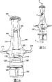
Fig. 1 a-1e represents the needleless injector according to one embodiment of the invention.Fig. 1 a is before carrying out injection, the side perspective view of syringe when central axis rotation 0 is spent, Fig. 1 b is a side sectional view, wherein syringe has rotated 90 degree around central axis, Fig. 1 c is the side perspective view of syringe when central axis rotation 0 is spent, and Fig. 1 d is after carrying out injection, the side perspective sketch map of syringe when central axis rotation 180 is spent, Fig. 1 e is after carrying out injection, the lateral parts cutaway view of syringe when central axis rotation 90 is spent.
Fig. 2 a-2c represents the shell according to the needleless injector of one embodiment of the invention.Fig. 2 a is the side perspective view when the central axis rotation 180 of syringe is spent, and Fig. 2 b is the near-end perspective view, and Fig. 2 c is the far-end perspective view.
Fig. 3 a-3c represents the ampoule lid (ampoulecap) according to the needleless injector of one embodiment of the invention.Fig. 3 a is a side perspective view, and Fig. 3 b is a side sectional view, and Fig. 3 c is the near-end perspective view.
Fig. 4 a-4c represents the plunger according to the needleless injector of one embodiment of the invention.Fig. 4 a is a side perspective view, and Fig. 4 b is a side sectional view, and Fig. 4 c is the near-end perspective view.
Fig. 5 a-5d represents the piston according to one embodiment of the invention.Fig. 5 a is a side perspective view, and Fig. 5 b is a side sectional view, and Fig. 5 c is the near-end perspective view, and Fig. 5 d is the far-end perspective view.
Fig. 6 a-6d is the bubbler according to the needleless injector of one embodiment of the invention.Fig. 6 a is a side perspective view, and Fig. 6 b is a side sectional view, and Fig. 6 c is the near-end perspective view, and Fig. 6 d is the far-end perspective view.
Fig. 7 a-7i is the various groove structures according to the bubbler of the needleless injector of some embodiments of the present invention.
Fig. 8 a-8d represents the trigger according to the needleless injector of one embodiment of the invention.Fig. 8 a rotates 0 side perspective view when spending around the central axis of trigger, and Fig. 8 b rotates 90 side sectional views when spending, and Fig. 8 c is the near-end perspective view, and Fig. 8 d is the far-end perspective view.
Fig. 9 a-9b represents the safety clamp according to the needleless injector of one embodiment of the invention.Fig. 9 a is the near-end perspective view, and Fig. 9 b is a side perspective view.
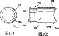
Figure 10 a-10d represents the motor body according to the needleless injector of one embodiment of the invention.Figure 10 a is a side perspective view, and Figure 10 b is a side sectional view, and Figure 10 c is the near-end perspective view, and Figure 10 d is the far-end perspective view.
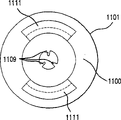
Figure 11 a-11d represents the valve according to the needleless injector of one embodiment of the invention.Figure 11 a is a side perspective view, and Figure 11 b is a side sectional view, and Figure 11 c is the near-end perspective view.
Figure 12 a-12c represents the closed lasso according to the needleless injector of one embodiment of the invention, and it is in by the state before mechanical assembly is around valve and the motor body.Figure 12 a is a side perspective view, and Figure 12 b is a side sectional view, and Figure 12 c is the near-end perspective view.
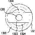
Figure 13 a-13d represents the threaded valve rod guiding piece according to the needleless injector of one embodiment of the invention.The side perspective view that Figure 13 a is partly cut open.Figure 13 b is a side sectional view, and Figure 13 c is the near-end perspective view, and Figure 13 d is the far-end perspective view.
Figure 14 a-14c represents the valve rod according to the needleless injector of one embodiment of the invention.Figure 14 a is a side perspective view, and Figure 14 b is the side sectional view before far-end is formed, and Figure 14 c is the near-end perspective view.
Figure 15 a-15b represents the valve spring according to the needleless injector of one embodiment of the invention.Figure 15 a is the side perspective view that is in the valve spring of relaxed state, and Figure 15 b is the side perspective view that is in the valve spring of compressive state.
Figure 16 is the curve charts of expression one embodiment of the invention in the speed of carrying out injection drive device.
The specific embodiment
As be used to illustrate that as shown in the accompanying drawing of the present invention, the present invention is implemented by a kind of gas-pressured needled-less injector.In a preferred embodiment of the invention, gas-pressured needled-less injector is by pre-loaded medicine, and is suitable for special purpose.Preferably, this needleless injector is used for people or other animal.Yet, should be appreciated that embodiments of the invention can also be used to other the application scenario that needs Needleless injection, for example, be used to make injectable substance to pass the application scenario of porous membrane or analog.
In addition, embodiments of the invention also can be used to inject other fluid or injection, for example protein, vitamin, hormone, anesthetics, vaccine, medicine, freeze dried medicine, medicine cocktail or analog, these fluids or injection all are included in the scope of terminology used here " liquid ".In some preferred embodiments, before liquid used in the present invention is in being loaded into this needleless injector, outgased, or, employed liquid has enough chemical characteristics, so that these liquid in a single day be loaded after immediately or the very fast degassing, as described in the U.S. Patent application of submitting to March 14 calendar year 2001 [acting on behalf of file number No.69816-025082].In in these preferred embodiments any one, before using,, in the inner chamber at described liquid place, there is not air pocket to form basically at the memory period of needleless injector.
Various elements of the present invention for convenience of description will adopt following space coordinates.Shown in Fig. 1 c, along central axis 1 of length qualification of gas-pressured needled-less injector 100.Central axis 1 has an end points at near-end 2 places of needleless injector 100, and during the syringe normal running, this end points is used as and the end of injecting surperficial this equipment that contacts.Another end points of central axis is positioned at far-end 3 places of syringe 100, and when syringe was oriented to perpendicular to the injection surface, this end points was the end apart from injection surface this equipment farthest.Therefore, each element of equipment of the present invention can be described with reference to separately proximal part and distal portions and their central axis.
As shown in Figure 1, a gas-pressured needled-less injector 100 comprises a shell 201.Although in a preferred embodiment, shell 201 roughly is the drum around central axis, and this shell 201 also can be any suitable shape.Preferably, shell 201 has the internal diameter that varies along its length, and can hold the element that is positioned at this shell and operates at this shell when being assembled fully with convenient syringe 100.Shell 201 shown in Fig. 2 a has four such internal diameters: an ampoule diameter 202, a piston diameter 203, a bubbler diameter 204 and an engine diameters 205.Preferably, embodiments of the invention do not have ampoule, and described ampoule is meant and is different from an organ of shell 201 that still, shell 201 can be used as and is used for for example ampoule of fill liquid of various purposes isolating.
Although in a preferred embodiment, the outside 206 of the proximal end face of shell 201 is can make the maximized shape of syringe effect,, it also can be flat.Whole basically liquid in being contained in syringe 100 can be transferred by injecting the surface, thereby after finishing, injection (sees Fig. 1 d, 1e) on the outside 206 of the proximal end face of shell 201 or injection surface basically not during residual liquid, the effect of syringe is best.In order to reach this purpose, in the embodiment shown in Fig. 2 a, when the outside 206 of the proximal end face of shell 201 and an injection surface contacts, the outside 206 of the near-end of shell 201 is suitable for pinching and stretching will be carried out the surface of injection operation.Therefore, preferably, the outside 206 of the near-end of shell 201 has the taper shape around central axis, and has margin of uplift 207 along its circumference.
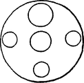
The inside 208 of the near-end of shell 201 can be any suitable shape.It can conform to the shape of outside 207 roughly, also can have independently profile.In one embodiment, described inner 208 is flat, but preferably, and shown in Fig. 2 a, it is conical that this inside 208 roughly is, and 210 places, summit or near have at least one hole 209.Only has a hole in the needleless injector 100 shown in Figure 1.
Described at least one hole 209 makes that forming fluid between the inside 214 of shell 201 and the surface that will carry out injection operation is communicated with.Can be according to the number that is changed hole 209 by the transportation parameters of injecting fluid.One of them parameter is that liquid is penetrated into the in-house necessary degree of depth of receiver when this equipment is used in human body injectable drug.For example, in one embodiment, only may wish liquid infusion therefore, to adopt a plurality of holes can adapt to this purpose best below receiver's the outermost skin layer.Or, penetrate deeply so that drug effect is reached for the maximum situation for needs, it is optimal adopting single hole.
Can produce a passing away 211 by shell 201, this passing away extends to outer wall 213 from inwall 212, and preferably is positioned at the sections of the shell 201 with ampoule diameter 202.Passing away 211 allows gas to discharge from the inside 214 of shell 201, preferably only allows gas to discharge after carrying out injection.Therefore, most preferably be, passing away 211 is set at the such some place in the shell 201, that is, this is carrying out the far-end (seeing Fig. 1 d and 1e) that is positioned at piston 500 residing positions or is positioned at the residing position of piston after the injection.In these most preferred embodiment, in shell 201, held basically all liquid all discharge and make after piston 500 stops at its final position from this needleless injector 100, gas could be discharged by this passing away 211 from the inside 214 of shell 201.
Before carrying out injection, be stored in liquid in the needleless injector 100 and preferably be accommodated in such zone in the inside 214 of shell 201, promptly should be limited (seeing Fig. 1 a and 2a) by the inside 208 of the near-end of shell 201, the inwall 212 of shell 201 and the near-end 403 of plunger 400 in the zone.
Shown in Fig. 2 a, shell 201 can comprise that also some depend on part 215.In a preferred embodiment, be provided with two at the relative position place of the outer wall 213 of shell 201 and such depend on part 215.Most preferably be that these are depended on part 215 and are configured to directly opposed mutually.In some preferred embodiments, each is depended on part 215 and has a curved arc 216 at its nearside, so that can suitably place finger, thereby can inject voluntarily or be injected etc. by the care professional.In more most preferred embodiment, the curved arc 216 of depending on part 215 also has anti-skidding grain surface 217.
When user adopts this needleless injector 100 to carry out injection voluntarily, on the thumb of described user and the middle opposite side that can be held in place shell 201 these are depended in the curved arc 216 of part 215, so that make this equipment keep stable, and make forefinger operationally abut against the trigger 800 of the far-end of syringe 100.The another kind of mode that user can be carried out injection voluntarily is, forefinger and middle finger are held in place in the curved arc of depending on part 215 on shell 201 mutually opposed, so that make this equipment keep stable, and thumb is operationally abutted against the trigger 800 of the far-end of syringe 100, when the people except the receiver of injection operated this needleless injector 100, this mode also was a kind of preferred mode.
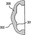
As shown in Figure 3, the near-end of shell 201 can also assemble ampoule lid 300, and this ampoule lid 300 is used for keeping the aseptic of the outside 206 of shell 201 proximal end face when needleless injector 100 is stored.In addition, when de-gas liq used according to the invention, this ampoule lid 300 can provide necessary hermetic seal between described at least one hole 209 in the near-end of shell 201 and local atmosphere, thereby can make the liquid that has taken off gas keep not containing the state of gas between the storage life.With reference to Fig. 3, preferably, the inside 301 of ampoule lid 300 is designed to basically to match with the outer surface of the near-end of shell 201, and the outside 302 of ampoule lid 300 can be designed to any structure easily.
As shown in Figure 4, shell 201 can be equipped with a plunger 400.Preferably, these plunger 400 compression fit are in described shell 201, and the diameter of this plunger 400 is equal to or slightly greater than the ampoule diameter 202 of shell 201.Preferably, plunger 400 is made by having enough elastic material, forms gas and liquid seal between the inwall 212 of this compression fit part and shell 201 so that make.Although under the not cylindrical situation of the inwall 212 of shell 201, plunger 400 also can adopt other shape that is fit to, and preferably, plunger 400 is cylindrical, and the shape of the inwall 212 of it and shell 201 is the mirror image matching relationship.In addition, can be provided with many lug, nibs 402 on the wall 401 of plunger 400.Preferably, being provided with at least two such lug, nibs 402, most preferably is that three lug, nibs 402 are set.These lug, nibs 402 provide stability for plunger 400, thereby during carrying out injection the moving direction of plunger 400 are remained along central axis basically linearly, and can not rotate around any axis beyond the central axis.
The near-end 403 of plunger 400 can be configured to Any shape, comprises the plane surface shape, although in a preferred embodiment, the shape of this near-end 403 is the mirror image matching relationship with the inwall 208 of the near-end of shell 201 substantially.Yet when utilizing mechanical force to make the near-end of plunger abut against when surface, the near-end 403 that the elasticity of plunger material can allow plunger 400 adapts with the surface configuration that is different from it self shape or cooperates.Therefore, the shape of the near-end 403 of plunger 400 needn't with 208 one-tenth mirror image corresponding relations of inwall of the near-end of shell 201, still, during carrying out injection or carry out after the injection, when the plunger near-end abutted against inwall 208, plunger near-end 403 can adapt with the shape of inwall 208.Yet in most preferred embodiment, it is conical that the shape of the near-end 403 of plunger 400 is basically.
Similarly, the far-end 404 of plunger 400 can be any suitable shape, and is accepted by the near-end of piston 500.In a preferred embodiment, the shape of plunger 400 is about a plane symmetry perpendicular to central axis.Accordingly, in a preferred embodiment, the shape of the far-end 404 of plunger 400 is conical substantially.
As shown in Figure 5, shell 201 can be equipped with a piston 500.Although the inwall 212 at shell 201 is not among the columniform embodiment, piston 500 also can adopt other shape that is fit to, but preferably, being shaped as along its central shaft line length direction of piston 500 is cylindrical substantially, and has one towards the open part 501 of opening of its far-end.Preferably, the shape of the near-end 502 of piston 500 is made into mechanically to accept the far-end 404 of plunger 400.Therefore, in most preferred embodiment, the near-end 502 of piston 500 is substantially a conical cavity.In a preferred embodiment, piston 500 also comprises a chamber 503, and the central axis of this chamber 503 from conical cavity 502 along piston 500 extends.
Preferably, the outside of the distal segment of piston is one and opens part 501, and ends at an expansion cupping edge 504.In most preferred embodiment, the distal segment of piston also has the expansion cup 505 of a hollow.Because chamber 503 extends from the near-end 502 of piston 500 along the piston middle spindle line, but be not to pass whole piston 500 to extend, therefore, this expand cup 505 not with chamber 503 gas communications.
With reference to Fig. 2 a and Fig. 5, the distal segment of piston 500 can compactedly be engaged in the part with piston diameter 203 of shell 201, thereby the diameter of the expansion cupping edge 504 of piston 500 is substantially equal to the piston diameter 203 of shell 201.Perhaps, the diameter of expansion cupping edge 504 also can be slightly smaller than the piston diameter 203 of shell 201.During using this needleless injector 100, owing to press against the active force of the Compressed Gas on the cup 505 that expands, the cup 505 that expands can radially expand.Owing between the inwall 202 of expansion cupping edge 504 and shell 201, form hermetic seal basically, so this can optimize the operating characteristics of piston 500.
As shown in Figure 6, shell 201 can be equipped with a bubbler 600.Preferably, this bubbler 600 is fixed on the shell 201 at bubbler diameter 204 part places along the inwall 212 of shell.This fixing can adopt high-frequency welding or other suitable mode to carry out.Most preferably be only after plunger 400 and piston 500 have been closed in the shell 201, this bubbler 600 to be fixed on the shell 201.
Preferably, bubbler 600 also comprises at least one passage 601, and described passage 601 provides gas communication between the base portion of the far-end 602 of bubbler 600 and volume expander 603.The size of described at least one passage 601 and position are configured to the injection delivery parameter of particular fluid is optimized.In a preferred embodiment, as shown in Figure 7, bubbler 600 can comprise two to eight passages 601.The diameter of these passages 601 can be identical, also can be different.These passages 601 can be configured to about the central axis symmetry of bubbler 600 or asymmetric.In bubbler 600, the selection of the various combination of passage 601 can influence the conveying characteristic of needleless injector 100, for example can change the initial acceleration of the driver of needleless injector 100.Figure 16 illustrates the speed of the driver in the preferred embodiments of the present invention.Should be noted that compressed gas engine of the present invention allows to have the constant transporting velocity of substantially constant during injection medicament.
With reference to Fig. 6 b, also can comprise a valve rod brace groove 604 at the far-end 602 of bubbler 600, this valve rod brace groove 604 is positioned on the central axis of bubbler.Bubbler 600 also can comprise a locking ring 605 along its periphery.Preferably, the distal surface 606 of locking ring 605 is at an angle or tilts, and its proximal end face 607 is flat.
As shown in Figure 8, shell 201 also can be equipped with a trigger 800.Preferably, this trigger 800 is cylindrical substantially, to match with the shape of the outer wall 213 of shell 201.Can be provided with a groove 801 in the far-end of trigger 800, in a preferred embodiment, this groove 801 also can be by veining, so that above can being placed on finger during this needleless injector 100 of operation and non-slip.
Preferably, trigger 800 comprises at least one fixation hook mechanism 802, this fixation hook mechanism 802 both had been used for trigger 800 is fixed to shell 201, also be used to relax because of the expansion that is stored in the Compressed Gas in the engine on housing 1000 produce recoil.If there is not this security feature, by the power that release produced that is stored in the gas in the motor body 1000 remainder of engine pack and needleless injector 100 is separated so, thereby can cause incorrect injection potentially, and can injure user.
In the time of around the fixation hook 803 of fixation hook mechanism 802 near-ends is locked in successive sawtooth lug, nib 219, described at least one fixation hook mechanism 802 operationally be arranged on shell 201 far-ends near described at least one breech lock maintaining body 218 cooperate, wherein said sawtooth lug, nib 219 preferably comprises described breech lock maintaining body 218.In a preferred embodiment, have two fixation hook mechanisms 802, they are positioned on the trigger 800 opposed to each other, and spatially corresponding with two breech lock maintaining bodies 218 on the outer wall 213 of motor body 201.
Preferably, described at least one fixation hook mechanism 802 and at least one breech lock maintaining body 218 can stop trigger 800 to rotate around its central axis.In most preferred embodiment, the side 804 of described at least one fixation hook mechanism 802 be engaged in described at least one breech lock maintaining body 218 side 222 around, thereby can stop described rotation.
Preferably, shell 201 is equipped with an engine pack 101, shown in Fig. 1 b.This engine pack 101 also can comprise a motor body 1000, as shown in figure 10.Preferably by the making of impermeable material for the gas of storing this motor body 1000 in, motor body 1000 has the internal chamber 1003 of a hollow for motor body 1000.Most preferably be that motor body 1000 is made by rustless steel or metalloid.Preferably, utilize compressed noble gas to drive this needleless injector 100, and before using described compressed inert gas storage in motor body 1000.Most preferred gas is carbon dioxide, but the gas that also can adopt other to be fit to.In most preferred embodiment, engine pack 101 so that can use in various height above sea levels, and can not be hindered the operating characteristics of this needleless injector 100 by undue load (that is, the Compressed Gas of storing excess in this engine pack 101).
Preferably, motor body 1000 is roughly cylindrical, so that cooperate with the inwall 212 of shell 201.Although also can adopt other planform.With reference to Figure 10, motor body 1000 has a major diameter part 1001 and a small diameter portion 1002, wherein, and small diameter portion 1002 and major diameter part 1001 next-door neighbours.The far-end of motor body 1000 can comprise a circular groove 1004, and can abut against described trigger 800 (seeing Fig. 1 b).The near-end of motor body 1000 comprises an opening 1005, in a preferred embodiment, utilizes a closed lug, nib 1006 around described opening 1005.
Preferably, engine pack 101 also comprises a valve 1100, as shown in figure 11.Preferably, the overall shape of valve 1100 is roughly cylindrical, more preferably is, valve is positioned at motor body 1000 at least in part.The periphery of valve 1100 preferably has a closure lugs 1101, and this closure lugs 1101 abuts against described closed lug, nib 1006, and described closed lug, nib 1006 is around the opening 1005 of motor body 1000 near-ends.Most preferably be, a closed lasso or ferrule 1200 are wrapped in around closure lugs 1101 and the closed lug, nib 1006, so that make valve 1100 and motor body 1000 interfix (seeing Fig. 1 b).
Figure 12 shows mechanically the closed lasso 1200 of closed lasso 1200 bendings before around closure lugs 1101 and the closed lug, nib 1006.The proximal part 1202 of closed lasso 1200 has identical diameter with the outside of valve 1100 basically, thereby just makes distal portions mechanically crooked, thereby can be connected to valve 1100 on the motor body 1000.In Fig. 1, the distal portions 1201 that shows closed lasso 1200 is in crooked state.Valve 1000 preferably has a groove 1102, and this groove 1102 is around the periphery of valve, to be used to install a packing ring 1103 (shown in Fig. 1 b).Packing ring 1103 helps to guarantee to keep hermetic seal between the inner atmosphere of the inside of the motor body 1000 that accommodates gas and needleless injector 100.
With reference to Figure 11, the inside of valve 1100 is hollow preferably, and be made up of several different pieces.The far-end inside 1104 of valve 1100 can comprise a threaded connection 1105, and this threaded connection 1105 is preferably from the far-end of remote extension to the one first axial chamber 1106 of valve 1100.The near-end of the described first axial chamber 1106 can be limited by a shoulder 1107, this shoulder 1107 is separated this first axial chamber 1106 and one second axial chamber 1108, and the diameter of the described second axial chamber 1108 is preferably less than the diameter of the first axial chamber 1106.In a preferred embodiment, shoulder 1107 is sloping edges.In addition, in a preferred embodiment, at least one valve rod guiding piece 1109 is outstanding from the wall of the second axial chamber 1108.In most preferred embodiment, be provided with three such valve rod guiding pieces 1109 at least, so that during carrying out injection, can prevent basically that valve rod 1400 from moving along any direction beyond the central axis of needleless injector 100.
The near-end of the second axial chamber 1108 preferably ends at bubbler and accepts chamber 1110, and this bubbler is accepted chamber 1110 and had enough diameters, so that make it can be around the far-end 602 of bubbler 600.After utilizing needleless injector 100 to carry out injection, the far-end 602 of bubbler 600 preferably is positioned at bubbler and accepts chamber 1110.
The near-end that bubbler is accepted chamber 1110 preferably has from its extended at least one clamp bar 1111.Preferably, when this clamping element 1112 is positioned at this clamp bar 1111 inboard, described at least one clamp bar 1111 be locked in a needleless injector 100 another suitable element around.Yet in alternative embodiment, because clamping element 1111 can be set at the outside of this clamp bar 1111, therefore described at least one clamp bar 1111 can be locked in another element internal.In most preferred embodiment, be provided with two clamp bars 1111, these two clamp bars 1111 are provided with opposed to each other, and each clamp bar all comprises a clamping element 1112, and this clamping element 1112 is positioned at the inboard of this clamp bar 1111.In these most preferred embodiment, in case carry out injection, described two clamp bars 1111 are just around sliding on the locking ring 605 of bubbler 600 and being locked in this locking ring 605.Because injection slips over described locking ring 605 up to clamp bar 1111 and just is carried out, being combined with of locking ring 605 and clamp bar 1111 helps slow down the recoil that produces because of the expansion that is stored in the Compressed Gas in the engine pack 101, thereby guarantees that user can be fully and correctly push described trigger 800.
Valve 1100 preferably also comprises a screwed valve guiding piece 1300, as shown in figure 13.This screwed valve guiding piece 1300 is preferably cylindrical, and its outer wall 1301 is provided with screw thread, thereby by interacting with threadedly engaged portions 1105, can be screwed into this valve guiding piece in the far-end inside 1104 of valve 1100.Most preferably be that the far-end of the screw thread on the outer wall 1301 of screwed valve guiding piece 1300 along whole outer wall 1301 from this threaded valve guiding piece 1300 is to proximal extension.This threaded valve guiding piece 1300 also can comprise a cylindrical inner chamber 1302, and this chamber 1302 is straightway at near-end.Yet far-end the pick of ground is covered with by a valve rod guide plate 1303.Valve rod guide plate 1303 preferably is provided with at least one aperture 1304, so that form gas communication between the internal chamber 1003 of the hollow of the motor body 1000 of the far-end of the internal chamber 1302 of threaded valve guiding piece 1300 and threaded valve guiding piece 1300.In addition, preferably, valve rod guide plate 1303 comprises a hole 1305 at the central axis place, and the slightly larger in diameter in this hole 1305 is in the diameter of the valve rod 1400 that is positioned at it.Most preferably be, valve rod guide plate 1303 also comprises a spring base 1306 on its proximal end face, and this spring base 1306 is made of at least one lug, nib 1307, and described lug, nib 1307 remains on correct position to valve spring 1500.
Preferably, valve 1100 also comprises a valve rod 1400, as shown in figure 14.Valve rod 1400 preferably is made of a cylindrical basically bar 1401, and this cylindrical bar 1401 has a near-end 1402 and a far-end 1403, and described near-end 1402 is flat, described far-end 1403 preferably be stamped or hammering forged.Figure 14 a represents the far-end 1403 after the hammering forging, and Figure 14 b represents the far-end 1403 before the hammering forging.Most preferably be, can be provided with a spring lug, nib 1404, this spring lug, nib 1404 extends radially from bar 1401, and be provided with one and roughly be conical valve head 1405, this valve head 1405 is fixed near the spring lug, nib 1404 the outer surface, and is positioned near the part of the bar 1401 the spring lug, nib 1404.Most preferably be that in this needleless injector 100, valve head 1405 is made by elastomeric material, is for example made by the semipermeability silicon-based rubber with enough ductility.In most preferred embodiment, the proximal end face of valve head 1405 and the angle between the central axis are substantially equal to the angle of the first axial chamber 1106 and the shoulder 1107 between the second axial chamber 1108 of valve 1100.
In addition, valve of the present invention can be repeatedly opened and cut out, and can not be damaged.Therefore, before engine pack 101 filling Compressed Gas, by opening and closing described valve at least once, thereby valve is carried out quality examination.In any equipment that uses this mechanism, defective valve is a worrying thing.But, being used for the needleless injector of medicinal application, valve is even more important, because defective valve can cause incorrect medicament dosage.
During utilizing this needleless injector to carry out injection, several mechanisms are used to slow down because of discharge the recoil that Compressed Gas produces from motor body.Clamp bar on the valve operationally links to each other with locking ring on the outer surface of bubbler, and the fixation hook in the fixation hook mechanism operationally is locked in each successive sawtooth place of breech lock maintaining body.These security features not only can be avoided the injury that may cause, but also have guaranteed that liquid can correctly carry by injecting the surface.
Example:
The operational circumstances of needleless injector
Before use, according to the present invention needleless injector is assembled, except engine pack, all elements of this needleless injector all are carried out the gamma-rays sterilization.By opening and closing described valve, thereby carry out quality control, then the Compressed Gas that filling is fit in motor body with the check engine pack.Then the enclosure between the near-end of the near-end of shell and plunger is filled with 0.5 milliliter liquid.The just assembled time storage that forms and can prolong of this then needleless injector.
When being ready to so that (see Fig. 1 a), user is removed the ampoule lid from the near-end of shell when using.Then, user also by the bending and/or twist and warp described safety clamp, thereby this safety clamp is also removed.If user is injected voluntarily, so just select following mode for use: the forefinger of user and middle finger are placed in the curved arc of depending on part, so that make this equipment keep stable, and thumb is operationally abutted against described trigger.Then, make the near-end of needleless injector be oriented to be approximately perpendicular to the injection surface.
Then, the user squeezing trigger abuts against up to the near-end of trigger and to limit the lug, nib that clamps the breach near-end.During trigger moved, when fixation hook locking piece process constituted the continuous sawtooth of breech lock maintaining body, fixation hook mechanism and breech lock maintaining body interacted.
Then, moving axially of trigger makes motor body, valve and screwed valve guiding piece move.Therefore, when the distal portions of bubbler slipped into and partly accepts chamber by the bubbler of valve and rest in this chamber, the clamp bar that is positioned at the valve near-end was locked in around the locking ring of bubbler.Simultaneously, valve rod is along with trigger moves, yet in case valve rod contacts with valve rod brace groove in the bubbler, this valve rod just keeps static with respect to shell.During approximately when slip on the locking ring of clamp bar at bubbler and through this locking ring, valve rod and bubbler arrive this Mechanical Contact state.
When valve rod and bubbler Mechanical Contact, valve spring is compressed, and along with valve head separates with shoulder between the valve first axial chamber and the second axial chamber, this valve is opened.So Compressed Gas (first axial cavity that is stored in the internal chamber of motor body, screwed valve guiding piece and valve in advance is indoor) is by the Clearance Flow between valve head and the shoulder.At least one groove that described gas is accepted in chamber and the described bubbler by the second axial chamber, process valve rod guiding piece, the bubbler of flowing through flows.Then, these gas fillings are by the formed space of expansion cup of volume expander and piston, force volume expander and before these two elements of cup that expand separate at gas, and the volume expander and the cup that expands are close mutually or be abutted against each other together.Gas enters in this space, applies active force at proximal direction to piston, thereby promotes plunger by enclosure, and forces liquid to enter from syringe at least one hole by its proximal end and/or by the injection surface.Piston and plunger coordination and as a driver.In case plunger abuts against the near-end of shell, unnecessary gas can be discharged by the passing away in the shell.Then, user just can be disposed this needleless injector, has so just finished injection.
Although top description is carried out at certain embodiments of the present invention,, those of ordinary skill in the art knows, under the situation that does not break away from design of the present invention, can make a large amount of modification to the present invention.Appended claim should comprise these modification, and these modification belong within design of the present invention and the scope.Therefore, described here embodiment is indicative, and the present invention is not limited to these embodiment.Scope of the present invention is limited to the appended claims, rather than the description done by the front limits.Protection scope of the present invention also comprises the equivalent and the equivalency range of claim.
Claims (48)
1. one kind is used for by a surface injection one fluidic needleless injector, and described needleless injector comprises:
One shell, it holds described fluid, and described shell also comprises at least one hole;
At least one breech lock maintaining body, it is set at the outside of described shell;
One electromotor, it is slidably mounted within the described shell, and described electromotor comprises:
One motor body, it has a closed distal end, a near-end and is defined in the hollow interior chamber between described near-end and the far-end, and described near-end limits an opening that passes it, accommodates gas in the described internal chamber;
One valve, it passes the described opening of described near-end, and is positioned at described motor body at least in part;
One driver, this driver force described fluid to flow out described shell, and described driver is slidably disposed in the described shell, and between described valve and described at least one hole;
One trigger, this trigger links to each other with described shell, and is configured to contact with the far-end of described motor body when described trigger is activated; And
At least one fixation hook mechanism, it is set on the described trigger, and described at least one fixation hook mechanism interacts with described breech lock maintaining body with being aligned.
2. needleless injector according to claim 1 is characterized in that, described at least one fixation hook mechanism and described at least one breech lock maintaining body operationally interact, thereby allow described trigger only to move axially along the longitudinal axis of described shell.
3. needleless injector according to claim 1 is characterized in that described needleless injector also comprises a bubbler, and this bubbler is fixed on the described shell, is provided with at least one passage in the described bubbler, and described valve comprises:
One valve rod, this valve rod have a spring lug, nib;
One valve head, this valve head are fixed on described valve rod and the described spring lug, nib;
One valve rod guiding piece, it is fixed on the described electromotor;
One valve spring, first end of this valve spring abuts against described spring lug, nib, and second end of this valve spring abuts against described valve rod guiding piece.
4. needleless injector according to claim 3 is characterized in that, in case push described trigger, described valve is just just opened.
5. needleless injector according to claim 1 is characterized in that, described driver comprises:
One piston; And
One plunger.
6. needleless injector according to claim 5 is characterized in that described plunger is symmetric; And described plunger and described shell form a gastight basically sealing.
7. needleless injector according to claim 5 is characterized in that, described plunger comprises:
One cone-shaped nose;
One conical rear end; And
One cylinder-shaped body.
8. needleless injector according to claim 7 is characterized in that, described plunger also comprises at least one lug, nib around described cylinder-shaped body.
9. needleless injector according to claim 5 is characterized in that, described piston comprises an expansion cup.
10. needleless injector according to claim 1 is characterized in that, also comprises ampoule lid, and this ampoule lid is detachably connected on the described shell, and wherein said ampoule covers and form a hermetic seal on the described hole of described shell.
11. needleless injector according to claim 1 is characterized in that, described shell also comprises a passing away.
12. needleless injector according to claim 1 is characterized in that, described trigger also comprises an end that has non skid matting.
13. needleless injector according to claim 3 is characterized in that, described bubbler also comprises a locking ring, and described electromotor also comprises at least one clamp bar.
14. needleless injector according to claim 1, it is characterized in that, also comprise a safety clamp, this safety clamp is detachably connected on the described shell, and wherein said safety clamp is used to prevent that described trigger from moving with respect to described shell along the axial direction in described at least one hole.
15. needleless injector according to claim 1 is characterized in that, described shell comprises that also at least one depends on part.
16. needleless injector according to claim 1 is characterized in that, described shell also comprises two mutual opposed parts of depending on, and describedly depends on part and also has a non skid matting.
17. one kind is used for by a surface injection one fluidic needleless injector, described needleless injector comprises:
One shell, it holds described fluid, and described shell also comprises at least one hole;
One electromotor, it is slidably mounted within the described shell, and described electromotor comprises:
One motor body, it has a closed distal end, a near-end and is defined in the hollow interior chamber between described near-end and the far-end, and described near-end limits an opening that passes it, accommodates gas in the described internal chamber;
One valve, it passes the described opening of described near-end, and is positioned at described motor body at least in part;
One driver, this driver force described fluid to flow out described shell, and described driver is slidably disposed in the described shell, and between described valve and described at least one hole; And
One trigger, this trigger links to each other with described shell, and is configured to contact with the far-end of described motor body when described trigger is activated;
Wherein, pushing described trigger can make described valve open; And
Described valve can withstand repeatedly and open.
18. needleless injector according to claim 17 is characterized in that, described valve comprises:
One valve rod, this valve rod have a spring lug, nib;
One valve head, this valve head are fixed on described valve rod and the described spring lug, nib;
One valve rod guiding piece, it is fixed on the described electromotor;
One valve spring, first end of this valve spring abuts against described spring lug, nib, and second end of this valve spring abuts against described valve rod guiding piece.
19. needleless injector according to claim 17 is characterized in that, described needleless injector comprises that also one is fixed to the bubbler on the described shell, is provided with at least one passage in the described bubbler.
20. needleless injector according to claim 17 is characterized in that, described driver comprises:
One piston; And
One plunger.
21. needleless injector according to claim 20 is characterized in that, described plunger is symmetric; And
Described plunger and described shell form a gastight basically sealing.
22. needleless injector according to claim 20 is characterized in that, described plunger comprises:
One cone-shaped nose;
One conical rear end; And
One cylinder-shaped body.
23. needleless injector according to claim 22 is characterized in that, described plunger also comprises at least one lug, nib around described cylinder-shaped body.
24. needleless injector according to claim 20 is characterized in that, described piston comprises an expansion cup.
25. needleless injector according to claim 17 is characterized in that, also comprises ampoule lid, this ampoule lid is detachably connected on the described shell, and wherein said ampoule covers and form a hermetic seal on the described hole of described shell.
26. needleless injector according to claim 17 is characterized in that, described shell also comprises a passing away.
27. needleless injector according to claim 17 is characterized in that, described trigger also comprises an end that has non skid matting.
28. needleless injector according to claim 17 is characterized in that, described trigger also comprises at least one fixation hook mechanism, and described shell also comprises at least one breech lock maintaining body.
29. needleless injector according to claim 19 is characterized in that, described bubbler also comprises a locking ring, and described electromotor also comprises at least one clamp bar.
30. needleless injector according to claim 17, it is characterized in that, also comprise a safety clamp, this safety clamp is detachably connected on the described shell, and wherein said safety clamp is used to prevent that described trigger from moving with respect to described shell along the axial direction in described at least one hole.
31. needleless injector according to claim 17 is characterized in that, described shell comprises that also at least one depends on part.
32. needleless injector according to claim 17 is characterized in that, described shell also comprises two mutual opposed parts of depending on, and describedly depends on part and also has a non skid matting.
33. one kind is used for by a surface injection one fluidic needleless injector, described needleless injector comprises:
One shell, it holds described fluid, and described shell also comprises at least one hole;
One electromotor, it is slidably mounted within the described shell, and described electromotor comprises:
One motor body, it has a closed distal end, a near-end and is defined in the hollow interior chamber between described near-end and the far-end, and described near-end limits an opening that passes it, accommodates gas in the described internal chamber;
One valve, it passes the described opening of described near-end, and is positioned at described motor body at least in part;
One driver, this driver force described fluid to flow out described shell, and described driver is slidably disposed in the described shell, and between described valve and described at least one hole;
One trigger, this trigger links to each other with described shell, and is configured to contact with the far-end of described motor body when described trigger is activated; And
At least one clamp bar, it is set on the described electromotor.
34. needleless injector according to claim 33 is characterized in that, described needleless injector also comprises a bubbler, and this bubbler is fixed on the described shell, is provided with at least one passage in the described bubbler, and described valve comprises:
One valve rod, this valve rod have a spring lug, nib;
One valve head, this valve head are fixed on described valve rod and the described spring lug, nib;
One valve rod guiding piece, it is fixed on the described electromotor; And
One valve spring, first end of this valve spring abuts against described spring lug, nib, and second end of this valve spring abuts against described valve rod guiding piece.
35. needleless injector according to claim 34 is characterized in that, by pushing described trigger described valve is opened.
36. needleless injector according to claim 33 is characterized in that, described driver comprises:
One piston; And
One plunger.
37. needleless injector according to claim 36 is characterized in that, described plunger is symmetric; And
Described plunger and described shell form a gastight basically sealing.
38. needleless injector according to claim 36 is characterized in that, described plunger comprises:
One cone-shaped nose;
One conical rear end; And
One cylinder-shaped body.
39., it is characterized in that described plunger also comprises at least one lug, nib around described cylinder-shaped body according to the described needleless injector of claim 38.
40. needleless injector according to claim 36 is characterized in that, described piston comprises an expansion cup.
41. needleless injector according to claim 33 is characterized in that, also comprises ampoule lid, this ampoule lid is detachably connected on the described shell, and described ampoule covers and form a hermetic seal on the described hole of described shell.
42. needleless injector according to claim 33 is characterized in that, described shell also comprises a passing away.
43. needleless injector according to claim 33 is characterized in that, described trigger also comprises an end that has non skid matting.
44. needleless injector according to claim 33 is characterized in that, described trigger also comprises at least one fixation hook mechanism, and described shell also comprises at least one breech lock maintaining body.
45. needleless injector according to claim 34 is characterized in that, described bubbler also comprises a locking ring, and described electromotor also comprises at least two clamp bars.
46. needleless injector according to claim 33, it is characterized in that, also comprise a safety clamp, this safety clamp is detachably connected on the described shell, and wherein said safety clamp is used to prevent that described trigger from moving with respect to described shell along the axial direction in described at least one hole.
47. needleless injector according to claim 33 is characterized in that, described shell comprises that is also depended on a part.
48. needleless injector according to claim 33 is characterized in that, described shell also comprises two mutual opposed parts of depending on, and describedly depends on part and also has a non skid matting.
Applications Claiming Priority (1)
| Application Number | Priority Date | Filing Date | Title |
|---|---|---|---|
| PCT/US2001/012099 WO2002083211A1 (en) | 2001-04-13 | 2001-04-13 | Modular gas-pressured needled-less injector |
Publications (2)
| Publication Number | Publication Date |
|---|---|
| CN1511049A CN1511049A (en) | 2004-07-07 |
| CN1262315C true CN1262315C (en) | 2006-07-05 |
Family
ID=21742497
Family Applications (1)
| Application Number | Title | Priority Date | Filing Date |
|---|---|---|---|
| CN01823321.XA Expired - Fee Related CN1262315C (en) | 2001-04-13 | 2001-04-13 | Modular gas-pressured needled-less injector |
Country Status (8)
| Country | Link |
|---|---|
| EP (1) | EP1379298A1 (en) |
| JP (1) | JP2004526519A (en) |
| CN (1) | CN1262315C (en) |
| AU (1) | AU2001253458C1 (en) |
| BR (1) | BR0116984A (en) |
| CA (1) | CA2444275A1 (en) |
| MX (1) | MXPA03009385A (en) |
| WO (1) | WO2002083211A1 (en) |
Cited By (2)
| Publication number | Priority date | Publication date | Assignee | Title |
|---|---|---|---|---|
| CN101797411A (en) * | 2010-03-18 | 2010-08-11 | 傅雅芬 | Air-pressure type needleless injector power head |
| CN103816588A (en) * | 2012-11-16 | 2014-05-28 | 厄比电子医学有限责任公司 | Needleless injection device |
Families Citing this family (12)
| Publication number | Priority date | Publication date | Assignee | Title |
|---|---|---|---|---|
| US7449012B2 (en) | 2004-08-06 | 2008-11-11 | Meridian Medical Technologies, Inc. | Automatic injector |
| US8048035B2 (en) | 2004-08-06 | 2011-11-01 | Meridian Medical Technologies, Inc. | Automatic injector with needle cover |
| US8221347B2 (en) | 2004-12-01 | 2012-07-17 | Acushot, Inc. | Needle-free injector |
| AU2012205735B8 (en) * | 2011-01-10 | 2014-09-18 | Zogenix, Inc. | Needle free injectors |
| RU2595504C2 (en) * | 2011-04-04 | 2016-08-27 | Айди Интернешнл Научно-Исследовательская И Опытно-Конструкторская Корпорация | Safety syringe for needleless injector |
| GB201210082D0 (en) * | 2012-06-07 | 2012-07-25 | Consort Medical Plc | Improved syringe |
| JP6253938B2 (en) * | 2013-09-30 | 2017-12-27 | 株式会社松風 | Viscous material container having an annularly contacting piston |
| GB2519970B (en) * | 2013-11-01 | 2017-06-14 | Consort Medical Plc | Medicament delivery device sub-assembly |
| CN103977480B (en) * | 2014-05-14 | 2016-06-15 | 苏州大学张家港工业技术研究院 | A kind of manually driven energy-storage type needleless injector |
| CA3101995C (en) | 2018-06-08 | 2023-10-10 | Antares Pharma, Inc. | Auto-insert injector |
| CN114867522A (en) * | 2019-12-31 | 2022-08-05 | 考尔得产品公司 | Sterile fluid coupler |
| CN115539826B (en) * | 2022-10-09 | 2023-04-11 | 湖南金航船舶制造有限公司 | A filling device for LNG ship |
Family Cites Families (11)
| Publication number | Priority date | Publication date | Assignee | Title |
|---|---|---|---|---|
| US2680439A (en) * | 1948-09-08 | 1954-06-08 | Arnold K Sutermeister | High-pressure injection device |
| US2754818A (en) * | 1950-06-24 | 1956-07-17 | Scherer Corp R P | Hypo jet injector |
| GB964585A (en) * | 1960-03-23 | |||
| FR1378829A (en) * | 1963-03-01 | 1964-11-20 | Apparatus for injecting liquid without the use of a needle, in particular into a living body | |
| US3557784A (en) * | 1968-12-24 | 1971-01-26 | Walter A Shields | Syringe |
| AU628029B2 (en) | 1987-11-16 | 1992-09-10 | Sy-Quest International Limited | Improved apparatus for hypodermic injection of liquids |
| US4913699A (en) | 1988-03-14 | 1990-04-03 | Parsons James S | Disposable needleless injection system |
| GB9408500D0 (en) * | 1994-04-28 | 1994-06-22 | Pa Consulting Services | Improvements in or relating to injection devices |
| US5730723A (en) | 1995-10-10 | 1998-03-24 | Visionary Medical Products Corporation, Inc. | Gas pressured needle-less injection device and method |
| US6080130A (en) | 1998-11-14 | 2000-06-27 | Castellano; Thomas P. | Gas power source for a needle-less injector |
| US6264629B1 (en) * | 1998-11-18 | 2001-07-24 | Bioject, Inc. | Single-use needle-less hypodermic jet injection apparatus and method |
-
2001
- 2001-04-13 AU AU2001253458A patent/AU2001253458C1/en not_active Ceased
- 2001-04-13 JP JP2002581012A patent/JP2004526519A/en active Pending
- 2001-04-13 WO PCT/US2001/012099 patent/WO2002083211A1/en not_active Application Discontinuation
- 2001-04-13 BR BR0116984-0A patent/BR0116984A/en not_active IP Right Cessation
- 2001-04-13 MX MXPA03009385A patent/MXPA03009385A/en unknown
- 2001-04-13 CA CA002444275A patent/CA2444275A1/en not_active Abandoned
- 2001-04-13 CN CN01823321.XA patent/CN1262315C/en not_active Expired - Fee Related
- 2001-04-13 EP EP01926961A patent/EP1379298A1/en not_active Withdrawn
Cited By (3)
| Publication number | Priority date | Publication date | Assignee | Title |
|---|---|---|---|---|
| CN101797411A (en) * | 2010-03-18 | 2010-08-11 | 傅雅芬 | Air-pressure type needleless injector power head |
| CN101797411B (en) * | 2010-03-18 | 2011-12-07 | 傅雅芬 | Air-pressure type needleless injector power head |
| CN103816588A (en) * | 2012-11-16 | 2014-05-28 | 厄比电子医学有限责任公司 | Needleless injection device |
Also Published As
| Publication number | Publication date |
|---|---|
| AU2001253458C1 (en) | 2006-05-18 |
| CN1511049A (en) | 2004-07-07 |
| WO2002083211A1 (en) | 2002-10-24 |
| BR0116984A (en) | 2004-06-29 |
| CA2444275A1 (en) | 2002-10-24 |
| MXPA03009385A (en) | 2004-11-12 |
| JP2004526519A (en) | 2004-09-02 |
| AU2001253458B2 (en) | 2005-10-27 |
| EP1379298A1 (en) | 2004-01-14 |
Similar Documents
| Publication | Publication Date | Title |
|---|---|---|
| CN1262315C (en) | Modular gas-pressured needled-less injector | |
| US6613010B2 (en) | Modular gas-pressured needle-less injector | |
| US9265886B2 (en) | Medicine injection apparatuses | |
| US7798989B2 (en) | Needleless syringe provided with a damping injector receptacle | |
| CN1126572C (en) | Pre-filled retractable needle injection ampoules | |
| CN1168508C (en) | Needleless syringe for injecting liquid contained prefilled ampule | |
| US20050192530A1 (en) | Method and apparatus for needle-less injection with a degassed fluid | |
| US20070049873A1 (en) | Impulse chamber for jet delivery device | |
| PT1441787E (en) | Pneumatic powered autoinjector | |
| US6824526B2 (en) | Engine and diffuser for use with a needle-less injector | |
| BRPI0718847A2 (en) | UNPROVED NEEDLE GUN AND FLUID DISPENSE METHOD | |
| CN1147207A (en) | Needleless jet injection device | |
| JPS62502876A (en) | Pharmaceutical component automatic mixing syringe device | |
| SK12502002A3 (en) | Miniaturized needleless injector | |
| JP2005087722A (en) | Sequential impulse/delivery fluid medicament injector | |
| AU2001253458A1 (en) | Modular gas-pressured needle-less injector | |
| US11786662B2 (en) | Ampule autoinjector systems and methods | |
| EP3377148B1 (en) | Autoinjector | |
| JP6942716B2 (en) | Needleless injection device with sliding membrane |
Legal Events
| Date | Code | Title | Description |
|---|---|---|---|
| C06 | Publication | ||
| PB01 | Publication | ||
| C10 | Entry into substantive examination | ||
| SE01 | Entry into force of request for substantive examination | ||
| C14 | Grant of patent or utility model | ||
| GR01 | Patent grant | ||
| C19 | Lapse of patent right due to non-payment of the annual fee | ||
| CF01 | Termination of patent right due to non-payment of annual fee |