CN1255603C - Method for removing water from fibre fabric by adopting vibration reflux to impact air - Google Patents
Method for removing water from fibre fabric by adopting vibration reflux to impact air Download PDFInfo
- Publication number
- CN1255603C CN1255603C CNB03142337XA CN03142337A CN1255603C CN 1255603 C CN1255603 C CN 1255603C CN B03142337X A CNB03142337X A CN B03142337XA CN 03142337 A CN03142337 A CN 03142337A CN 1255603 C CN1255603 C CN 1255603C
- Authority
- CN
- China
- Prior art keywords
- width
- cloth sheet
- gas
- air
- impact
- Prior art date
- Legal status (The legal status is an assumption and is not a legal conclusion. Google has not performed a legal analysis and makes no representation as to the accuracy of the status listed.)
- Expired - Fee Related
Links
Images


Classifications
-
- F—MECHANICAL ENGINEERING; LIGHTING; HEATING; WEAPONS; BLASTING
- F26—DRYING
- F26B—DRYING SOLID MATERIALS OR OBJECTS BY REMOVING LIQUID THEREFROM
- F26B15/00—Machines or apparatus for drying objects with progressive movement; Machines or apparatus with progressive movement for drying batches of material in compact form
- F26B15/10—Machines or apparatus for drying objects with progressive movement; Machines or apparatus with progressive movement for drying batches of material in compact form with movement in a path composed of one or more straight lines, e.g. compound, the movement being in alternate horizontal and vertical directions
- F26B15/12—Machines or apparatus for drying objects with progressive movement; Machines or apparatus with progressive movement for drying batches of material in compact form with movement in a path composed of one or more straight lines, e.g. compound, the movement being in alternate horizontal and vertical directions the lines being all horizontal or slightly inclined
- F26B15/18—Machines or apparatus for drying objects with progressive movement; Machines or apparatus with progressive movement for drying batches of material in compact form with movement in a path composed of one or more straight lines, e.g. compound, the movement being in alternate horizontal and vertical directions the lines being all horizontal or slightly inclined the objects or batches of materials being carried by endless belts
-
- D—TEXTILES; PAPER
- D21—PAPER-MAKING; PRODUCTION OF CELLULOSE
- D21F—PAPER-MAKING MACHINES; METHODS OF PRODUCING PAPER THEREON
- D21F11/00—Processes for making continuous lengths of paper, or of cardboard, or of wet web for fibre board production, on paper-making machines
- D21F11/14—Making cellulose wadding, filter or blotting paper
- D21F11/145—Making cellulose wadding, filter or blotting paper including a through-drying process
-
- D—TEXTILES; PAPER
- D21—PAPER-MAKING; PRODUCTION OF CELLULOSE
- D21F—PAPER-MAKING MACHINES; METHODS OF PRODUCING PAPER THEREON
- D21F5/00—Dryer section of machines for making continuous webs of paper
-
- D—TEXTILES; PAPER
- D21—PAPER-MAKING; PRODUCTION OF CELLULOSE
- D21F—PAPER-MAKING MACHINES; METHODS OF PRODUCING PAPER THEREON
- D21F5/00—Dryer section of machines for making continuous webs of paper
- D21F5/006—Drying webs by using sonic vibrations
-
- D—TEXTILES; PAPER
- D21—PAPER-MAKING; PRODUCTION OF CELLULOSE
- D21F—PAPER-MAKING MACHINES; METHODS OF PRODUCING PAPER THEREON
- D21F5/00—Dryer section of machines for making continuous webs of paper
- D21F5/18—Drying webs by hot air
-
- F—MECHANICAL ENGINEERING; LIGHTING; HEATING; WEAPONS; BLASTING
- F26—DRYING
- F26B—DRYING SOLID MATERIALS OR OBJECTS BY REMOVING LIQUID THEREFROM
- F26B13/00—Machines and apparatus for drying fabrics, fibres, yarns, or other materials in long lengths, with progressive movement
- F26B13/10—Arrangements for feeding, heating or supporting materials; Controlling movement, tension or position of materials
-
- F—MECHANICAL ENGINEERING; LIGHTING; HEATING; WEAPONS; BLASTING
- F26—DRYING
- F26B—DRYING SOLID MATERIALS OR OBJECTS BY REMOVING LIQUID THEREFROM
- F26B13/00—Machines and apparatus for drying fabrics, fibres, yarns, or other materials in long lengths, with progressive movement
- F26B13/24—Arrangements of devices using drying processes not involving heating
-
- F—MECHANICAL ENGINEERING; LIGHTING; HEATING; WEAPONS; BLASTING
- F26—DRYING
- F26B—DRYING SOLID MATERIALS OR OBJECTS BY REMOVING LIQUID THEREFROM
- F26B23/00—Heating arrangements
- F26B23/02—Heating arrangements using combustion heating
- F26B23/026—Heating arrangements using combustion heating with pulse combustion, e.g. pulse jet combustion drying of particulate materials
-
- F—MECHANICAL ENGINEERING; LIGHTING; HEATING; WEAPONS; BLASTING
- F26—DRYING
- F26B—DRYING SOLID MATERIALS OR OBJECTS BY REMOVING LIQUID THEREFROM
- F26B5/00—Drying solid materials or objects by processes not involving the application of heat
- F26B5/02—Drying solid materials or objects by processes not involving the application of heat by using ultrasonic vibrations
Abstract
A process and an apparatus for removing water from a fibrous web are disclosed. The process comprises providing a fibrous web having a moisture content from about 10% to about 90%; providing an oscillatory flow-reversing impingement gas having frequency of from 15 Hz to 1500 Hz; providing a gas-distributing system comprising a plurality of discharge outlets designed to emit the oscillatory flow-reversing impingement gas onto the web; and impinging the oscillatory flow-reversing gas onto the web through the plurality of discharge outlets, thereby removing moisture from the web. The apparatus comprises a web support designed to receive a fibrous web thereon and to carry it in a machine direction; at least one pulse generator designed to produce oscillatory flow-reversing air or gas; and at least one gas-distributing system in fluid communication with the pulse generator for delivering the oscillatory flow-reversing air or gas to the web. The gas-distributing system terminates with a plurality of discharge outlets juxtaposed with the web support such that the web support and the discharge outlets form an impingement distance therebetween, the plurality of the discharge outlets comprising a predetermined pattern defining an impingement area of the web.
Description
The application is that application is artificial: Paper Science ﹠ Technology Inst, and the applying date is: on June 29th, 1999, application number is: 99807673.2, name is called: adopt oscillatory flow-reversing impingement gas to remove the dividing an application of invention of the method for moisture from fibrous web.
Invention field
The present invention relates to the manufacture method of the absorbent fibrous web of a kind of high strength, softness.Especially, the present invention relates to the dehydration of fibrous web.
Background technology
Fibre structure as paper web, is produced by various methods.For example, can produce paper web according to following patent: the patent U.S.5556509 that was presented to people such as Trokhan on September 17th, 1996 with commonly-assigned us, be presented to people's such as Ampulski United States Patent (USP) 5580423 on December 3rd, 1996, be presented to the United States Patent (USP) 5609725 of Phan on March 11st, 1997, be presented to people's such as Trokhan United States Patent (USP) 5629052 on May 13rd, 1997, be presented to people's such as Ampulski United States Patent (USP) 5637194 on June 10th, 1997, and on October 7th, 1997 be presented to people's such as McFarland United States Patent (USP) 5674663, the disclosure of these patents is at this as a reference.Paper web also can adopt the through-air drying manufactured, as described in: the United States Patent (USP) 4514345 that was presented to people such as Johnson on April 30th, 1985 in following patent with commonly-assigned us, be presented to the United States Patent (USP) 4528239 of Trokhan on July 9th, 1985, be presented to the United States Patent (USP) 4529480 of Trokhan on July 16th, 1985, on January 20th, 1987 was presented to the United States Patent (USP) 4637859 of Trokhan, and the United States Patent (USP) 5334289 that was presented to people such as Trokhan on August 2nd, 1994.The disclosed content of aforementioned patent at this as a reference.
In papermaking process, from paper, remove moisture and generally include several steps.Beginning, the aqueous suspension of fiber generally comprise and surpass 99% moisture and be less than 1% paper fibre.Almost 99% usefulness mechanical means of moisture is removed, and produces about 20% fiber consistency.Then, squeezing and/or heat operation, and/or through-air drying, or any their combination generally removes the moisture less than about 1%, and the fiber consistency in the width of cloth sheet is increased to about 60%.At last, residual moisture is removed in last drying process process (utilizing a dryer roll usually), thereby the fiber consistency in the width of cloth sheet is increased to about 95%.
Because so a large amount of moisture needs to remove, so in industrial paper technology, removing moisture is an operating unit the most catabiotic.According to a research, rank the first in the whole energy consumption industry papermaking that are used for drying, used above 3.75 * 10 in 1985
14Degree (BTU) heat people such as (, the competition situation of natural gas: industrial solid drying, energy and Environmental Studies, Inc., 1987) Salama.So, in paper technology, adopt more effective dewatered method to bring significant interests, as increasing machine power and reducing operating cost for paper industry.
The known impact air and the dryer roll of current stabilization of using in paper technology comes dry-web.(for example see people such as Polat, the drying of paper pulp and paper, the industrially drying handbook, 1987, pp.643-82).Usually, for tissue paper product, impingement hood is used with the Yankee dryer roll.In having the low relatively quantitative width of cloth sheet of approximately per 270 square metres of 3632-4994 grams (3000 square feet of 8-11 pounds), moisture was removed in 0.5 second greatly.This is equivalent to approximately per 0.09 square metre of evaporation rate of 19068 grams (every square feet per hour 42 pounds) per hour, finishes about 75% of whole evaporation capacity by impingement hood.Quantitatively the rate of drying of heavier relatively paper product is quite slow.For example, quantitatively be the newsprint of approximately per 270 square metre of 13620 gram (per 3000 square feet 30 pounds), the evaporation rate on dryer roll per hour 2270 restrains (every square feet per hour 5 pounds) for approximately per 0.09 square metre.For example see that people such as P.Enkvist are in June, 1997 12-13 day U.S. Oshkosh, Wisconsin, Valmet high speed and high temperature on the tissue machine that Valmet Technology Days ' 97 submits to are raised gram technology cover (the Valrnet High Velocityand Temperature Yankee Technology Hood on Tissue Machines).
Also known use acoustic wave energy as the energy that is produced by steam jet steam whistle, makes (to comprise in the paper) that from various products removing moisture becomes easy.On June 3rd, 1972 was presented to the United States Patent (USP) 3,668,785 of Rodwin, had lectured sound wave drying and impingement flow dry mixed drying means for a dry paper web.Be presented to people's such as Rodwin United States Patent (USP) 3 on October 3rd, 1972,694,926 have lectured a kind of paper drying machine, this paper drying machine has a sound wave arid region, width of cloth sheet is by this zone and stand the high strength noise that sends from the noisemaker that condenses together, makes moisture be separated from from width of cloth sheet.Be presented to people's such as Rodwin United States Patent (USP) 3 on August 7th, 1973,750,306 have lectured the sound wave drying of width of cloth sheet and roll, comprise along steam jet steam whistle and the inswept moisture that has shifted of second low-pressure air of carrying the slot type speculum to separate the width of cloth sheet that the cleaning operation is passed through.
Above-mentioned technology provides a kind of device that produces sound wave/acoustic energy and a kind of separator that produces current stabilization and impact/extract air.According to prior art by as noisemaker, steam jet steam whistle and analog generation acoustic energy, the sound source that required power is very big and cause tangible power consumption.Know general noisemaker in this area and as the efficient of steam whistle, loudspeaker, steam jet steam whistle and similar device, be no more than 10-25%.Also need other device, as compressed-air actuated compressor and produce the loudspeaker of required acoustic pressure, reach the drying effect of a hope.
Now, have been found that the impact of the air that has vibration reflux motion or gas, impact on the contrary, can bring significant benefit, comprise the higher dried/dewatered speed and the saving of the energy with the current stabilization of prior art to paper web.Can believe that with respect to prior art a kind of oscillatory flow-reversing impingement air or gas that has lower frequency is a kind of effective ways that improve heat and material Transfer speed in paper technology.
The pulse-combustion technology is a kind of known and method viable commercial that improves heat and material Transfer in heating power technology.Commercial use comprises the incineration of industry and domestic heat system, boiler, coal gasification, spray drying, hazardous waste.For example, below U.S. Patent Publication the commercial Application of several pulse-combustions: the United States Patent (USP) 5059404 that was presented to people such as Mansour on October 22nd, 1991, be presented to the United States Patent (USP) 5133297 of Mansour on July 28th, 1992, be presented to the United States Patent (USP) 5197399 of Mansour on March 30th, 1993, be presented to the United States Patent (USP) 5 of Mansour on April 27th, 1993,205,728, be presented to the United States Patent (USP) 5,211,704 of Mansour on May 18th, 1993, be presented to the United States Patent (USP) 5 of Mansour on October 26th, 1993, be presented to people's such as Mansour United States Patent (USP) 5 on April 26th, 255,634,1994,306, be presented to people's such as Mansour United States Patent (USP) 5,353 on October 11st, 481,1994, be presented to people's such as Mansour 5 on November 22nd, 721 and 1994,366,371, these patents are disclosed to be introduced in here as the reference of describing pulse-combustion.One piece write by people such as P.A.Eibeck, be published in " combustion science and technology " (1993, Vol.94, pp.147-165) title of article has been described a kind of method that improves convective heat exchange for " pulse-combustion: the reinforcement that impulse nozzle heat is transmitted ", comprise the use of pulse combustor, promptly produce the moment injection of an impact on one flat plate.This article report convective heat exchange is compared the raising coefficient with a current stabilization impact can reach 2.5.
The applicant believes, compares with existing dehydration and/or drying technique, and oscillatory flow-reversing impingement can also bring significant raising aspect the transmission of heat in dehydration of width of cloth sheet and/or the drying process and material.Especially, believe that oscillatory flow-reversing impingement can just improve paper making equipment speed, and/or reduce the mobile aspect of the air that is used for dry width of cloth sheet and bring significant benefit, reduce the volume and the fund cost of width of cloth sheet dried/dewatered operating equipment thus, thereby reduced whole paper technology cost.In addition, can believe that oscillatory flow-reversing impingement can make people accomplish that the even width of cloth flake products of density unevenness that the assignee is produced reaches one uniformly dry (at this as a reference) substantially.Can also believe that now oscillatory flow-reversing impingement can successfully be applicable to the dehydration and/or the drying of fibrous web, combine separately or with other dewatering process, as through-air drying, current stabilization impingement drying, and dryer roll drying.
In order to dewater effectively from width of cloth sheet, vibration reflux air or gas particularly traverse the width (promptly at machine transversely) of width of cloth sheet acting on the surface of width of cloth sheet in a kind of full and uniform mode under the situation mostly.Perhaps, people may wish to distinguish in a kind of specific in advance mode the application of the oscillatory flow-reversing impingement gas that traverses width of cloth sheet width, control the relative humidity and/or the rate of drying of width of cloth sheet non-uniform areas thus.Under above-mentioned any situation, for the vibration reflux air that spreads all over width of cloth sheet surface or the control of distribution of gas, and the especially control on transverse machine, be crucial for dewatered technology validity from width of cloth sheet.
The paper web that present plant-scale papermaking machine is produced, width has about 254cm to 1016cm (100 to 400 inches), and the linear velocity of operation is up to per minute 2135m (7000 feet).Width like this, the width of cloth sheet that is accompanied by high-speed motion causes the oscillating gas distribution control (evenly general) to spreading all over width of cloth sheet surface that certain difficulty is arranged.The existing equipment of vibration reflux air or gas, for example, pulse combustor, produce needed vibration zone uniform substantially, that cross a large-area relatively return air or gas is not (if not all right at all) that adapts to very much.
Therefore, an object of the present invention is to provide a kind of use oscillatory flow-reversing impingement gas dewatered method and apparatus from the fibrous web.Another object of the present invention provides a kind of gas distributed system, the vibration reflux air that people can be controlled effectively spread all over width of cloth sheet surface or the distribution of gas.A further object of the invention provides a kind of gas distributed system, makes vibration reflux air or gas obtain full and uniform application on width of cloth sheet.
Summary of the invention
The invention provides a kind of use vibration reflux air of novelty or gas dewatered method and apparatus as impact media and from fibrous web.The stage that apparatus and method of the present invention are can be in all processes of papermaking different uses, from a width of cloth sheet stage initial stage of moulding to the dried stage.Like this, fibrous web can have the humidity of a beginning in a big scope, and from about 10% to about 90%, that is, the fiber consistency of a fibrous web can from about 90% to about 10%.
Aspect its method, the present invention includes following steps: provide fibrous web; The oscillatory flow-reversing impingement gas that has preset frequency is provided, and frequency is preferably in the scope from 15Hz to 1500Hz; An a kind of lip-deep gas distributed system of predetermined portions that comprises a large amount of outlets and be used for oscillatory flow-reversing impingement gas is sent to width of cloth sheet is provided; With by a large amount of outlets vibration reflux gas is impacted on the width of cloth sheet, get on except that moisture from width of cloth sheet thus.Preferably, vibration reflux gas impacts on the width of cloth sheet with a kind of predetermined way that limits width of cloth sheet impact area.
The first step front that fibrous web is provided is some steps that form this width of cloth sheet, and it comprises the step that many paper fibres are provided.The present invention also attempts to adopt by dry air method into the net or wetting again width of cloth sheet and forms width of cloth sheet.Before removing moisture by method and apparatus of the present invention, width of cloth sheet can have a kind of moisture distribution heterogeneous, that is, the fiber consistency of width of cloth sheet some parts can be different from the fiber consistency of these width of cloth sheet other parts.
Removal moisture device of the present invention has a machine direction and the transverse machine perpendicular to this machine direction.The inventive system comprises: width of cloth sheet supporter is used for receiving fibrous web thereon and transmits this fibrous web along machine direction; At least one impulse generator is used to produce vibration reflux air or the gas of frequency from 15HZ to 1500HZ; And at least one and the gas distributed system that the impulse generator fluid is communicated with, be used for vibration reflux air or gas are sent to a presumptive area of width of cloth sheet.This gas distributed system ends at and the juxtaposed many floss holes of width of cloth sheet supporter (or on width of cloth sheet is arranged at the width of cloth sheet supporter time, with width of cloth sheet and put), forms shock zone between width of cloth sheet supporter and the floss hole.This shock zone is limited by impact distance Z.In other words, impact distance Z is the gap between floss hole and the width of cloth sheet supporter.Preferably, the predetermined distribution pattern of many floss holes defines width of cloth sheet impact area " E ".Vibration reflux gas can be impacted on the width of cloth sheet, so that a uniform distribution of gas of cardinal principle to be provided on whole width of cloth sheet shock zone.Replacedly, oscillating gas can be impacted on the width of cloth sheet to provide a uneven distribution of gas on whole width of cloth sheet shock zone, allows control width of cloth sheet moisture profile thus.
According to the present invention, impulse generator is a kind of device, and it is used to produce vibration reflux air or the gas with loop cycle speed/momentum component and Mean Speed/momentum component.Preferably, the acoustic pressure that is produced by impulse generator is converted into the large amplitude periodic motion, comprises positive period and negative cycle alternately, with respect to negative cycle, has bigger momentum and loop cycle speed positive period, as will be described in more detail as follows.
Preferred impulse generator comprises pulse burner, generally includes combustion chamber, air inlet, oil-in and resonating tube.This pipe is as the acoustic resonator work of the standard of generation sound wave.Resonating tube is that fluid is communicated with gas distributed system further.Define the combination of pipe, tail pipe, casing etc. here as used term " gas distributed system ", be designed for the passage that the vibration reflux air that produces for impulse generator or gas provide a sealing, and guiding vibration reflux air or gas enter a predetermined shock zone (limiting above), in the zone, vibration reflux air or gas are impacted on the width of cloth sheet, therefrom remove moisture thus.Gas distributed system is designed to reduce (preferably all avoiding) division interferes, and this division interference can influence the action required pattern of pulse combustor unfriendly, or the oscillating characteristic of the reflux gas that is produced by pulse combustor.Gas distributed system is sent to flow-reversing impingement air or gas on the width of cloth sheet, preferably by many exhaust outlets or nozzle.The optimized frequency of oscillatory flow-reversing impingement air or gas is in about 15HZ arrives about 1500HZ scope.Preferred frequency is from 15HZ to 500HZ, and most preferred frequency is from 15HZ to 250HZ, and this depends on the type of impulse generator and/or the characteristic of required moisture removal method.If impulse generator comprises pulse combustor, then optimized frequency is from 75HZ to 250HZ.In impulse generator of the present invention, can use a kind of Helmholtz type acoustic resonator.Helmholtz type impulse generator can be adjusted and reach a desirable audio frequency.In pulse combustor, in the oscillating gas temperature in floss hole exit from about 260 ℃ to about 1371 ℃ (about 500 °F to about 2500 °F).
Another embodiment of impulse generator comprises acoustic device one time.Inferior acoustic device comprises a resonant chamber that is communicated with the air intake fluid by pulsator.Pulsator produces infrasonic sound (low frequency) and presses the vibration air, and it is exaggerated in resonant chamber and resonating tube then.The frequency of the preferred vibration reflux air of this time acoustic device from 15Hz to about 100Hz.If desired, the device that comprises time acoustic device can have the device of the vibration reflux air that heating produces by this time acoustic device.
Oscillatory flow-reversing impingement air or gas have two components: one is to be the average weight of feature with Mean Speed V and corresponding mean momentum M; One is to be the vibration or the loop cycle component of feature with loop cycle speed and corresponding loop cycle momentum.During cycle of oscillation, burning gases move forward from the combustion chamber, and the cycle of oscillation that enters, passes and leave gas distributed system 30 is defined as " direct circulation "; The cycle of oscillation that impact air takes place to reflux is defined as " negative circulation ".The mean amplitude of tide of direct circulation is " a positive amplitude "; Negacyclic mean amplitude of tide is " a negative amplitude ".During direct circulation, impact air has one " positive speed ", and the edge is towards one " positive direction " being arranged on the width of cloth sheet on the width of cloth sheet supporter; In negative cycle period, impact air has one " negative speed ", along one " negative direction ".Positive direction is opposite with negative direction, and positive speed is opposite with negative speed.Positive speed component is greater than negative speed component, and Mean Speed has positive direction.
Pulse combustor produces a strong acoustic pressure from 160dB to 190dB usually in the combustion chamber.Acoustic pressure reaches its maximum in the combustion chamber.Because the openend of resonating tube, acoustic pressure reduces in the exit of resonating tube.The decline of this acoustic pressure causes the continuous increase of loop cycle speed, and its exit at resonating tube reaches its maximum.In preferred Helmholtz type impulse generator, acoustic pressure reaches minimum of a value in the resonating tube exit, so that reach a maximum cycle cycle rate of oscillatory surge gas exhaust stream.The acoustic pressure that reduces is of value to the relevant noise of velocity of sound increase process that reduces usually with prior art.
Exit in gas distributed system, loop cycle speed from about 305m (1000ft)/min to about 15250m (50000ft)/min, be preferably from about 762.5m (2500ft)/min to about 15250m (50000ft)/min, it calculates according to the acoustic pressure of measuring in the combustion chamber.Preferred loop cycle speed is to about 15250m (50000ft)/min from about 1525m (5000ft)/min.Mean Speed from about 305m (1000ft)/min to about 7625m (25000ft)/min, preferably, Mean Speed from about 762.5m (2500ft)/min to about 7625m (25000ft)/min, more preferably from about 1525m (5000ft)/min to about 7625m (25000ft)/min.
Believe the width of cloth sheet for moisture from 10% to 60%, apparatus and method of the present invention allow moisture removal speed to reach 756600g/m
2.hr (150lb/ft
2.hr) and higher.
In order to reach required moisture removal speed, oscillatory flow-reversing impingement gas should be preferably in form on the whole surface of width of cloth sheet this width of cloth sheet of even contact substantially a vibration " field of flow ".A kind of method of finishing it is that feasible oscillating gas from gas distributed system flows basically shunting equably and passes through the desiccated surface of floss hole network-impacting to width of cloth sheet.So device of the present invention is to be used for according to predetermined and best in check mode oscillatory flow-reversing impingement air or gas being discharged into width of cloth sheet.The distribution pattern of floss hole can change.Preferred distribution pattern comprises the staggered pattern of non-any arrangement.
The floss hole of gas distributed system can have many kinds of shapes, includes but are not limited to: circular, become rectangle and long oval seam shape or the like basically.Each floss hole has aperture area " A " and identical diameter " D ".Synthetic aperture area " ∑ A " refers to total aperture area that all the single aperture area A by floss hole form together.The area of any moment in continuous flow procedure by the width of cloth sheet part that the oscillatory flow-reversing impingement field is impacted is impact area " E ".
Preferably, width of cloth sheet is more preferably transmitted along machine direction by width of cloth sheet support body supports.In a preferred embodiment, the device of control impact distance can be set, for example traditional manual adjustment mechanism and automation equipment make the floss hole of gas distributed system and width of cloth sheet supporter relative to each other move.Can foretell that impact distance can respond from the signal of a parameter control device of at least one parameter of measuring width of cloth sheet dehydration or width of cloth sheet itself and be regulated automatically.In a preferred embodiment, impact distance can change from about 0.635 centimetre to about 15.24 centimetres (about 0.25 inch to about 6.0 inches).Impact distance defines a shock zone, that is, and and the zone between floss hole and width of cloth sheet supporter.In a preferred embodiment, the ratio (being A/D) from about 1.0 to about 10.0 of impact distance Z and floss hole equivalent diameter D.Ratio (being ∑ A/E) between synthetic aperture area " ∑ A " and the impact area E is from about 0.002 to about 1.000, and preferably from 0.005 to 0.200, more preferably from 0.010 to 0.100.
In one embodiment, gas distributed system comprises that at least one blows case.This blows case and comprises the base plate with many floss holes that pass.Blow the base plate that case can have a general planar shape.Replacedly, the base plate that blows case can have on-plane surface or curved shape, for example protrudes shape or recessed shape.In blowing an embodiment of case, formed a base plate that protrudes substantially by mass part.
Angled the applying of vibration reflux air or gas can be used for the present invention valuably.The angle that forms between the positive direction of width of cloth sheet supporter general surface (or surface of width of cloth sheet impact area E) and air by floss hole or gas oscillatory flow is from 0 to 90 degree almost.These angles can be orientated along machine direction, or along the transverse machine orientation, also can be along the third side between machine direction and the transverse machine to orientation.
On the width of width of cloth sheet, can adopt many gas distributed system.This set allows the condition of control width of cloth sheet dehydration on whole width of cloth sheet width that bigger flexibility is arranged.For example, this set allows the different machines lateral part of width of cloth sheet is controlled impact distance individually.If desired, single gas distributed system can a kind of non-any-mode, is preferably the surface distributed of staggered pattern at whole width of cloth sheet.
The oscillating field of flow-reversing impingement gas can be advantageously with impact width of cloth sheet on impact air stationary flow (non-oscillatory) impact air be used in combination.A preferred embodiment comprises vibration reflux gas and the steady flow gas that sequence alternate is used.In oscillating gas and the steady flow gas one or two comprises the injection stream that has angle with respect to width of cloth sheet supporter.
Width of cloth sheet supporter can comprise many structures, for example, and papermaking bar or band, fourdrinier wire or screen cloth, drying drum or the like.In a preferred embodiment, width of cloth sheet supporter moves with the speed of 30.5 meters of per minutes (100 feet) to 3050 meters of per minutes (10000 feet) along machine direction.More preferably, the speed of this width of cloth sheet supporter is that 305 meters of per minutes (1000 feet) are to 3050 meters of per minutes (10000 feet).Several key steps in whole paper-making process can be used device of the present invention, for example forming step, wet transfer step, predrying step, drying drum drying (as Yankee) step and back drying steps.An optimum position of shock zone be drying drum and and the juxtaposed drying hood of this drying drum between the zone that forms, in this case, width of cloth sheet supporter comprises the surface of drying drum.In one embodiment, impingement hood places roller drier " green end ".Drying residencing time can be by controlling around the cover of drying drum and the combination of machine speed.This method is specially adapted to eliminate the humidity difference that exists in the different densities structure paper web.
A preferred embodiment of width of cloth sheet supporter comprises the endless belt or the bar of fluid penetrable, the back surfaces that it has width of cloth sheet contact surface and faces toward width of cloth sheet contact surface.Such width of cloth sheet supporter preferably includes and is connected to the framework of strengthening structure, and at least one the fluid penetrable deflectable catheter that extends between width of cloth sheet contact surface and back surfaces.Framework can comprise continuous substantially structure.Replacedly or additionally, framework can comprise many discontinuous protuberances.Formed by continuous substantially framework as fruit bat sheet contact surface, then this width of cloth sheet contact surface comprises continuous substantially network; And at least one deflectable catheter comprises many this discontinuous conduits of continuous frame substantially that extend through, and each discontinuous conduit is surrounded by framework.
Adopt apparatus and method of the present invention, can remove moisture simultaneously from the different densities structure division of structure width of cloth sheet.The dehydration characteristic of this vibration reflux method and prior art adopt the conventional method of drying drum or through-air drying method to compare, the dehydration characteristic of above-mentioned vibration reflux method very on the low degree (if how much having a bit) depend on the difference of dehydrated width of cloth sheet density.So the water that method of the present invention has been eliminated above-mentioned dehydration is effectively removed influencing each other between relative density different of characteristic (speed of water removal more importantly) and dehydrated width of cloth sheet different piece.
No matter method of the present invention is to be used in combination separately or with the through-air drying method, can eliminate and use this step of drying drum in paper-making process.An advantageous applications of the inventive method is in conjunction with the through-air drying method, comprises the pressure of application examples as being produced by vacuum source.Device of the present invention can be valuably uses in conjunction with vacuum plant, and for example, in conjunction with vacuum pick boots or vacuum box, in this case, width of cloth sheet supporter is preferably fluid penetrable.Vacuum plant is preferably with the posterior face of width of cloth sheet supporter and put, more preferably in the zone corresponding to shock zone.Vacuum plant is applied to pressure on the width of cloth sheet by fluid penetrable width of cloth sheet supporter.In this case, the vibration reflux gas that forms by impulse generator and can cooperate valuably by the pressure that vacuum plant produces, each independent dewatering has increased the efficient of combination dewatering greatly with respect to those thus.
Randomly, device of the present invention can have from the dewatered servicing unit of shock zone (comprising the boundary layer).This servicing unit can comprise many with have the groove that atmospheric perimeter fluid is communicated with.Replacedly or as additionally, servicing unit can comprise that vacuum source and at least one zone from shock zone and/or contiguous this shock zone extend to the vacuum tank of vacuum source, provide fluid to be communicated with thus between them.
Brief description of drawings
Fig. 1 is the diagram diagrammatic side view of apparatus of the present invention and a kind of preferred continuous producing method, expresses impulse generator emission oscillatory flow-reversing impingement air or gas on the mobile width of cloth sheet of endless belt support;
Fig. 2 is a curve map, and the cycle rate Vc and the Mean Speed V of expression vibration reflux air or gas, cycle rate Vc comprise speed V1 and negative cycle speed V2 positive period;
Fig. 3 is the curve map that is similar to Fig. 2 curve map, and the speed Vc of indication cycle distributes with respect to the out-phase of acoustic pressure P;
Fig. 4 is the diagram diagrammatic side view of a pulse combustor, and it can be used in the apparatus and method of the present invention;
Fig. 4 A is that the circular floss hole of indicating impulse combustion chamber, discharge orifice have diameter D and aperture area A along the partial view of Fig. 4 center line 4A-4A intercepting;
Fig. 4 B is another embodiment of pulse combustor floss hole, and this floss hole is rectangular;
Fig. 5 is a curve map, is illustrated in the correlation between indoor acoustic pressure P of pulse-combustion and the positive speed Vc;
Fig. 6 is the diagram diagrammatic side view of an embodiment of apparatus of the present invention and method, represent that an impulse generator continues oscillatory flow-reversing impingement air or gas are alternately impacted on the width of cloth sheet with current stabilization impinging air or gas, width of cloth sheet is by supporting along the endless belt of machine direction operation;
Fig. 7 is the diagrammatic fragmentary view of apparatus of the present invention, comprises the dry hood of drying drum, and width of cloth sheet is supported by drying drum;
Fig. 7 A is the local diagrammatic, cross-sectional view of apparatus of the present invention, comprises width of cloth sheet supporter, and width of cloth sheet supporter comprises the drying drum and the impulse generator gas distributed system that comprises many floss holes that have width of cloth sheet on it;
Fig. 7 B is and view like Fig. 7 category-A, expresses width of cloth sheet supporter, and width of cloth sheet supporter comprises the band of a porous fluid, and width of cloth sheet is stamped between width of cloth sheet supporter and the drying drum surface, and vibration reflux gas is applied on the width of cloth sheet by width of cloth sheet supporter;
Fig. 8 is the diagrammatic view of the continuous papermaking process of the present invention, and expression apparatus of the present invention are with respect to some possible positions of whole paper-making process;
Fig. 9 is that indicating impulse generator floss hole is with respect to an embodiment of the non-arbitrary patterns on width of cloth sheet surface along the diagrammatical cross-sectional view of Fig. 1 center line 9-9 intercepting;
Fig. 9 A represents the graphic plan view of floss hole, comprises the rectangular aperture substantially that distributes with a kind of non-arbitrary patterns;
Figure 10 is the diagrammatic, cross-sectional view of a preferred embodiment of impulse generator gas distributed system, and this system closure is blown case in one, blows case and has many discharge orifices that extend its bottom that pass;
Figure 11 is a Ning section along Figure 10 center line 11-11 intercepting, represents a plurality ofly to blow case along what the machine direction consecutive intervals was opened;
Figure 12 is the diagrammatic, cross-sectional view of blowing an embodiment of case, and it has the convex bottom surface;
Figure 12 A is the graphic more detailed cross-sectional view that blows case shown in Figure 12, provides with respect to the porous width of cloth sheet of fluid supporter and has applied vibration air or gas in angled mode;
Figure 13 is the diagrammatical cross-sectional view of blowing an embodiment of case, blows the case bottom and comprises many built-up sections that interconnect, and forms the roughly convex of blowing the case bottom;
Figure 13 A is a diagrammatic curve figure, and what be illustrated in curved bottom with Figure 12 graphic representation blows the case exit, or in the vibration reflux gas that blows the case exit of the segmentation bottom with Figure 13 graphic representation or the Temperature Distribution of air;
Figure 14 is the diagrammatic, cross-sectional view of blowing case embodiment with crooked concave bottom;
Figure 14 A is a diagrammatic curve figure, is illustrated in the Temperature Distribution of the flow-reversing impingement gas that blows the case exit of the crooked concave bottom with Figure 14 graphic representation;
Figure 15 is the schematic side-view of a kind of production method embodiment of the present invention, and expression is along the spaced many impulse generators of cross-machine direction;
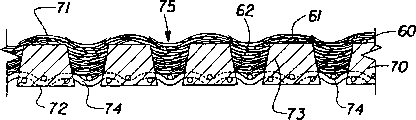
Figure 16 is the local schematic side-view of an embodiment of fluid penetrable width of cloth sheet supporter, and it comprises being connected to strengthens structural continuous substantially framework, above the width of cloth sheet supporter fibrous web is arranged;
Figure 17 is the local graphic plan view (for the clear fibrous web of not representing) of width of cloth sheet supporter shown in Figure 16;
Figure 18 is the local schematic side-view of an embodiment of fluid penetrable width of cloth sheet supporter, and it comprises many structural discontinuous ledges of reinforcement that are connected to, and has fibrous web above the width of cloth sheet supporter;
Figure 19 is the local graphic plan view (for the clear fibrous web of not representing) of width of cloth sheet supporter shown in Figure 180;
Figure 20 is the diagrammatic view that is used for an embodiment of impulse generator of the present invention, and it comprises acoustic device one time.
Detailed description of the present invention
The first step of production method of the present invention comprises provides fibrous web.Used here term " fibrous web " or simply " width of cloth sheet " 60 (Fig. 1 and 6-9) refer to macroscopical planar base layer, it includes cellulose fibre, synthetic fiber or their combination.Width of cloth sheet 60 can comprise (but being not limited only to) conventional method and through-air drying method with the known papermaking process manufacturing of any prior art.The suitable fibers that constitutes width of cloth sheet 60 can comprise regeneration or secondary stock, paper fibre and original paper fibre.This fiber can comprise hardwood fiber, cork fibrous and not have xylon.Term used herein " fibrous web " comprises quantitatively from per approximately 270 square metre of 3632 gram (per 3000 square feet 8 pounds) (lb/3000ft
2) to per approximately 270 square metre of 9080 gram (per 3000 square feet 20 pounds) (lb/3000ft
2) tissue web, and quantitatively from 25454g/90m
2(lb/1000ft
2) to about 1000454g/90m
2(lb/1000ft
2) plate level width of cloth sheet, comprise (but being not limited only to) quantitatively from 30 to 80454g/90m
2(lb/3000ft
2) level other brown paper width of cloth, quantitatively from 40 to 100454g/90m
2(lb/1000ft
2) other bleached paperboard of level, and have quantitatively about 30454g/90m of typical case
2(lb/3000ft
2) newsprint.
The first step front that fibrous web 60 is provided is some steps that form this width of cloth sheet.Those skilled in the art will recognize easily that forming width of cloth sheet 60 can comprise the step that many fibers 61 (Fig. 8) are provided.In the typical paper-making process continuously that Fig. 8 describes, many fibers 61 preferably are suspended in the liquid-carrier.More preferably, these fibers 61 comprise aqueous suspension.The equipment of the aqueous suspension of preparation fiber 61 is known in this area, thereby not shown in Fig. 8.The aqueous suspension of fiber 61 can be provided to flow box shown in Figure 8 65.Although an independent flow box 65 shown in Figure 8, being to be understood that in other of production process of the present invention is provided with to have a plurality of flow boxs.The equipment of one or more flow boxs and preparation fiber aqueous suspension generally has the disclosed form of United States Patent (USP) 3994771 that was presented to Morgan and Rich on November 30th, 1976, and this patent here as a reference.The preparation of paper fibre aqueous suspension and the characteristic feature of this aqueous suspension describe in detail in United States Patent (USP) 4529480 very much, and this patent at this as a reference.The present invention also designs and adopts the width of cloth sheet 60 that forms by the dry air net-forming process.This technology is for example at Technomic PublishingCo., and Lancaster, PA show in " valuable equipment of paper machine " (P.138) in 1997 S.Adanur that publish and be described.The present invention also can consider to use the width of cloth sheet that has been soaked again.Previous soaking again of dry width of cloth sheet of making can be used to make three-dimensional width of cloth chip architecture, for example by to soaking the embossing of width of cloth sheet again and then dry embossed web sheet makes.The present invention also can consider to use and authorized people such as Farrington on August 12nd, 1997 and transfer Kimberly-Clark Worldwide, inc.of Neenah, the paper technology that discloses among the United States Patent (USP) U.S.5656132 of Wisconsin.
As term " drying " meaning that is here adopted is by vaporization removal water (or moisture) from fibrous web 60.Vaporization comprises that water is from the liquid phase to the gas phase or the phase transformation of steam.Term " dehydration " meaning is not produce the phase transformation of water and remove water from width of cloth sheet 60 at the water of removing.Difference between drying and the dehydration is important in the context of the invention, and this is that a kind of mode of anhydrating can be more relevant than other mode of anhydrating because of the moment according to whole paper-making process (Fig. 8).For example, width of cloth sheet forms the stage (Fig. 8, I and II) in the early stage, and most of water are mainly removed by machinery equipment.Afterwards, in squeezing and/or heat operation and/or through-air drying (Fig. 8, III and IV) stage, need vaporization to remove moisture usually.
Be traditional and comprise dry and dehydration independent or that combine as term " removal water " or " moisture removal " (perhaps change of their arrangements) of adopting here.Similarly, term " removal moisture speed " or " moisture removal speed " (with the change of their arrangements) refer to dehydration, drying or their any combination.Similarly, term " dewater unit " is to be applied to device of the present invention, is used for getting on except that moisture from width of cloth sheet 60 by drying, dehydration or their combination.It is one of following that connection-separations combination of " dehydration and/or dry " (or dehydration/drying) simply comprises: the combination of dehydration, dehydration dry or qualification here and drying.
The form that water exists is depended in the success of dehydration in width of cloth sheet 60.Form the stage at width of cloth sheet, water can be present in width of cloth sheet 60 with several different forms: loose (with respect to whole water content about 20%), micropore (about 40%), colloid constraint (about 20%), and (1985 people such as H.Muralidhara that publish show " dry technology " 3 (4), 529-66.) to absorb (about 10%) with chemical method.Loose moisture can be removed by vacuum technique.Yet the water of removing from width of cloth sheet 60 in the micropore is more much more difficult than removing loose water, and this is owing to must overcome the cause of the capillary force between paper fibre and water.Because the strong hydrogen bonding that forms between paper fibre and water adopts general dewatering process can not remove the water of colloid constraint water and chemical method absorption usually from width of cloth sheet, must adopt heat treatment method to remove.Apparatus and method of the present invention can be applicable to remove the drying and the dewatering process of moisture.
Can be used for impulse generator of the present invention a type 20 and comprise acoustical generator and one pipe or tail pipe, this pipe has basic diameter uniformly, and an end is opened towards atmosphere, and the relative other end is closed, and the length L of pipe is a length measured (Fig. 4) between this pipe opposite end.Pipe produces fixedly sound wave as an acoustic resonator.As known in the art, fixedly sound wave has the node (minimum-rate and maximum pressure) of an antinode (maximum rate and minimum pressure) and a pipe blind end at the openend of pipe.Preferably, these set wave satisfy following condition: L=ω (2N+1)/4, and wherein, L is the length of pipe; ω is the wavelength of set wave, N be an integer (that is, and N=0,1,2,3 ..., etc.).
Wavelength is that (be L=ω/4, sound wave N=0) is confirmed as a kind of keynote to resonating tube 1/4 length usually in this area.Other sound wave is confirmed as first harmonic (N=1), second harmonic (N=2), and third harmonic (N=3) ..., etc.In the present invention, the length of preferred resonating tube equals 1/4 of frequency that acoustical generator produces, that is, preferred impulse generator 20 produces keynote sound waves, N=0.Fixedly sound wave provides the air pressure of change in the acoustic resonator tail pipe, has maximum pressure at the blind end of tail pipe acoustic resonator.The relation of sound wave and wavelength such as following formula: F=C/ ω, wherein F is an audio frequency, C is the velocity of sound.Produce under the situation of keynote at impulse generator 20, the relation between frequency and the wavelength can more specifically be represented by formula F=C/4L from the relation that limits previously.
Fig. 4 represents to comprise the preferred pulse generator 20 of pulse combustor 21.As shown in Figure 4, pulse combustor 21 comprises combustion chamber 13, air inlet 11, oil-in 12 and resonating tube 15.The part of term as used herein " resonating tube " 15 indicating impulse generators 20, it makes burning gases vibrate along its length with certain frequency, moves along the predetermined direction of being determined by the geometry of resonating tube 15 simultaneously.One skilled in the art will appreciate that frequency (that is, the frequency of burning gases of generation combustion chamber 13 in) when the power that be applied to resonating tube 15 equals or when approaching the natural frequency of resonating tube 15, sympathetic response occurs.In other words, impulse generator 20 (comprising resonating tube 15) is like this design, and promptly resonating tube 15 hot combustion gas that will produce combustion chamber 13 in converts vibration (that is, vibrating) flow-reversing impingement gas to.
In Fig. 4, air inlet 11 and oil-in 12 are that fluid is communicated with combustion chamber 13, are used for respectively gas and oil being sent to combustion chamber 13, and oil and gas mix a kind of flammable mixture of formation in this combustion chamber.Preferably, pulse combustor 21 also comprises igniter 14, and it is used for air and oil mixture in the ignition combustion chamber 13.Pulse combustor 21 also can comprise an intake valve 11a and an inlet valve 12a, is used for controlling respectively the transmission of empty G﹠O, and the combustion period parameter of pulse combustor 21.
Resonating tube 15 is communicated with gas distributed system 30 further fluids.Define the combination of pipe, tail pipe, casing etc. here as used term " gas distributed system ", be designed for the passage that the vibration reflux air that produces for impulse generator 20 or gas provide sealing, and guide the vibration reflux air thus or gas enters a predetermined shock zone, in the zone, vibration reflux air or gas are impacted on the width of cloth sheet 60, therefrom remove moisture thus.Gas distributed system 30 is designed to make division to interfere minimum (preferably avoiding fully), and this can influence the action required pattern of pulse combustor 21 on the contrary, or the oscillating characteristic of the reflux gas that is produced by pulse combustor 21.Those of ordinary skill in the art will understand, and in some possible embodiment of apparatus of the present invention 10 (Fig. 1,9 and 4) at least, gas distributed system 30 can comprise one or more resonating tubes 15.In other words, in some cases, resonating tube 15 can comprise the two intrinsic part of pulse combustor 21 and gas distributed system 30, as here limiting.In this case, being combined in here of one or more resonating tubes 15 and gas distributed system 30 is referred to as " sympathetic response gas distributed system ", and by label 35 expressions.For example, sympathetic response gas distributed system 35 can comprise many resonating tubes (or tail pipe) 15, as Fig. 4, shown in 1 and 9.In this, the difference between " gas distributed system 30 " and " sympathetic response gas distributed system 35 " is just pro forma, and term " gas distributed system " and " sympathetic response gas distributed system " are interchangeable under most of situation.
Regardless of its specific embodiment, gas distributed system 30 or sympathetic response gas distributed system 35 are sent to flow-reversing impingement air or gas on the width of cloth sheet 60, preferably by many exhaust outlets or nozzle 39.The optimized frequency F that impacts vibration reflux air on the width of cloth sheet 60 or gas at about 15HZ in about 1500HZ scope.Preferred frequency F is from 15HZ to 500HZ, and most preferred frequency F is from 15HZ to 250HZ.If impulse generator 20 comprises pulse combustor 21, then optimized frequency is from 75HZ to 250HZ.
A typical pulse combustor 21 is operated in the following manner.After air or oil entered combustion chamber 13 and mixes therein, igniter 14 was lighted the gas and oil mixture, and the startup of pulse combustor 21 is provided thus.Because increasing sharply of burning gas temperature, the burning of gas and oil mixture causes the unexpected increase of combustion chamber 13 inner volumes.When the burning gases of heat expanded, inlet valve 11a and 12a closed, and made burning gases expand thus and entered a resonating tube 15, and this resonating tube 15 is communicated with combustion chamber 13 fluids.In Fig. 4, resonating tube 15 also comprises gas distributed system 30, so just forms resonating tube gas distributed system 35 as above.Gas distributed system 30 has an exhaust outlet 39 that has aperture area at least, and aperture area is expressed as " A " in Fig. 4 A and 4B, comes out from gas distributed system 30 (Fig. 4) by this aperture area A thermal oscillation gas.
Those of ordinary skill in the art will be understood that Fig. 4 has described one type pulse burner 21, and it can be used to the present invention.Many pulse combustors are known in this area.These examples include but are not limited to: from The Fulton Companies of Pulaski, New York, the gas pulses burner of having bought; By J.Jireh Corporation of San Rafael, the impulse drying machine that California makes; By Sonotech, Inc.of Atlanta, the Cello stove that Georgia. produces.
Another embodiment of Figure 20 indicating impulse generator 20, it comprises time acoustic device 22.Inferior acoustic device 22 comprises resonant chamber 23, and it is communicated with by pulsator 24 fluids with air intake 11.Pulsator 24 produces the vibration air with inferior acoustic pressure (low frequency), and inferior acoustic pressure enlarges in resonant chamber 23 and resonating tube 15 then.Further comprise the equal isobaric flexible pipe 28 of air pressure that makes between pulsator 24 and the diffuser 26 at the inferior acoustic device 22 shown in Figure 20, be used for controlling the frequency converter case 25 and the acoustic wave action controller 27 of vibration frequency.In inferior acoustic device 22, also can use various valves, for example a kind of valve 26 of controlling fluid connection between acoustic wave action controller 27 and the air intake 11.If impulse generator 20 comprises time acoustic device 22, then the optimized frequency of vibration reflux air is that 15HZ is to 100HZ.Inferior acoustic device 22 among Figure 20 shown in the diagram is commercial by Infrafone AB Company of Sweden manufacturing, and brand name is INFRAFONE.Low-frequency sound generator is authorized people's such as Olsson United States Patent (USP) U.S.4517915 May 21 in 1985, authorized people's such as Olsson United States Patent (USP) U.S.4650413 on March 17th, 1987, authorized people's such as Olsson United States Patent (USP) U.S.4635571 on June 13rd, 1987, authorized people's such as Olsson United States Patent (USP) U.S.4592293 on June 3rd, 1986, authorize people's such as Olsson United States Patent (USP) U.S.4721395 in January, 1988, authorized on September 27th, 1994 among the United States Patent (USP) U.S.5350887 of Sandstrom and be described, the disclosure of these patents is used for describing generation low-frequency oscillation device here as a reference.
The device 10 that comprises time acoustic device 22 can have the device (not shown) that adds the thermal oscillation air, and the vibration air is by inferior acoustic device 22 dischargings.If necessary, this device can comprise electric heater or temperature control thermal transfer element, and this element is positioned at a zone of contiguous shock zone.Another kind of scheme is that width of cloth sheet 60 can be heated by width of cloth sheet supporter 70.Yet, should be understood that, (at least some steps of the paper-making process) in certain embodiments, inferior acoustic device 22 can not have heater.For example, can use time acoustic device 22, in this case, believe that time acoustic device 22 can operate at ambient temperature effectively in the predrying stage of paper-making process.Inferior acoustic device 22 also can be used to produce oscillating field, and this oscillating field is added on the current stabilization impact air then.
Comprise at impulse generator 20 under the situation of pulse burner 21 that the audio frequency of vibration reflux ripple partly depends on the characteristic (as inflammability) of the oil that uses at least in pulse burner 21.For two embodiment, pulse combustor 21 and the inferior acoustic device 22 of impulse generator 20, several other factors comprise the design and the geometry of resonance system 30, also can influence the sound field frequency that is produced by flow-reversing impingement air or gas.For example, if resonance system 30 comprises many resonating tubes 15, as Fig. 1 and Fig. 9 graphic representation, these factors include, but is not limited to the diameter D (Fig. 9) and the length L (Fig. 4) of one or more pipe 15 so, the quantity of pipe 15, and the ratio of the volume of the volume of resonating tube 15 and combustion chamber 13 (Fig. 4) or resonant chamber 23 (Figure 20).
A kind of Helmholtz type acoustic resonator can be used for impulse generator 20 of the present invention.One skilled in the relevant art will recognize that Helmholtz type acoustic resonator is a kind of vibrational system, generally include a large amount of occluded airs that have open neck or port.Helmholtz type acoustic resonator is similar to the same the acting on of resonating tube as above that has opening and blind end.The fixedly sound wave that has antinode produces at the openend of Helmholtz type acoustic resonator.Correspondingly, node is present in the shutdown side of Helmholtz type acoustic resonator.Helmholtz type acoustic resonator can have inconstant diameter (thereby having inconstant volume) along its length direction.Usually, Helmholtz type acoustic resonator comprises the bigger chamber with chamber volume Wr, and this chamber is connected to the resonating tube with pipe volume Wt.The combination of the part of different volumes produces sound wave.The preferred Helmholtz type acoustic resonator of Shi Yonging and such Helmholtz type impulse generator produce the fixedly sound wave of 1/4 wavelength under a given audio frequency in the present invention, and be such as described above.The frequency of sound wave of Helmholtz type impulse generator 20 can be represented by following formula: F=(C/2 π L) x (Wt/Wr)
0.5, wherein: F is the frequency of vibration reflux air or gas, and C is the velocity of sound, and L is the length of resonating tube, and Wt is the volume of resonating tube, Wr is the volume of combustion chamber 13.Like this, by adjusting chamber volume Wr, the length L of pipe volume Wt and pipe 15, Helmholtz type impulse generator 20 can be adjusted and reach a given audio frequency.
Because its high burning efficiency and high sympathetic response operator scheme are so comprise that the Helmholtz type impulse generator 20 of pulse combustor 21 is preferred.Helmholtz type pulse combustor 21 is created in the highest pressure oscillation of per hour every BTU (being British Thermal unit) that releases energy in the given volume Wr of combustion chamber 13 usually.The flow oscillations of formed higher value is providing a required increased pressure amount aspect the pressure drop that overcomes the downstream heat switching equipment.Pressure oscillation scope in the Helmholtz type pulse combustor 21 that the present invention adopts is (Q1 during the positive crest) usually from about 1si (Q2 during the negative peak) to about 5psi, as Fig. 2 graphic representation.These pressure oscillations produce the sound pressure level from about 120 decibels (dB) to about 190dB in combustion chamber 13.Fig. 3 is the curve map that is similar to curve map shown in Figure 2, and the speed Vc of indication cycle distributes with respect to the out-phase of acoustic pressure P.
Oscillatory flow-reversing impingement gas has two components: one is to be the average weight of feature with Mean Speed V and corresponding mean momentum M, and one is to be the vibration or the loop cycle component of feature with loop cycle speed Vc and corresponding loop cycle momentum Mc.Need not theoretical proof, the applicant believes that the average and oscillating component of oscillatory flow-reversing impingement gas mainly forms in the following manner.13 gas combustion products that enter distribution of gas resonance system 30 have big mean momentum (proportional with Mean Speed V and its quality of burning gases) from the combustion chamber.When the burning of gas and oil mixture basically after finish combustion chamber 13, combustion chamber 13 in, forms parital vacuum with the inertia of discharging the burning gases of combustion chamber 13 at a high speed, a part of burning gases of the feasible discharge of this vacuum are got back to combustion chamber 13.Remaining is discharged gas and leaves pulse combustor 21 by resonance system 30 with Mean Speed V.The parital vacuum that forms in combustion chamber 13 is opened inlet valve 11a and 12a, makes empty G﹠O enter combustion chamber 13 again thus; Burn cycle repeats.
As used herein, burning gases 13 move forward from the combustion chamber, and the cycle of oscillation that enters, passes and leave gas distributed system 30 is defined as " direct circulation "; The cycle of oscillation that impact air takes place to reflux is defined as " negative circulation ".Correspondingly, the mean amplitude of tide of direct circulation is " a positive amplitude "; Negacyclic mean amplitude of tide is " a negative amplitude ".Similarly, during direct circulation, impact air has " positive speed " V1, and the edge is towards " positive direction " D1 that is arranged on the width of cloth sheet 60 that is provided with on the width of cloth sheet supporter 70; In negative cycle period, impact air has " negative speed " V2, along " negative direction ".Positive direction D1 is opposite with negative direction D2, and positive speed V1 is opposite with negative speed V2.During the course, loop cycle speed Vc has defined the momentary rate at any given time Oscillation Flows gas, simultaneously, Mean Speed V has defined the final speed of backflow oscillating field, and the backflow oscillating field is formed by the burning gases (comprising a series of positive and negative circulations that replace) with frequency F vibration.Those of ordinary skill in the art will be understood that positive speed V1 greater than negative speed V2, and Mean Speed V has positive direction D1, thereby final oscillatory surge gas promptly enters gas distributed system 30 from pulse combustor 21 with positive direction D1 motion.Also should be appreciated that because cycle rate Vc constantly changes to and the opposite negative speed V2 of speed V1 just from positive speed V1, so, when changing its direction, cycle rate Vc certainly exists a kind of situation, promptly with respect to the situation of V1 and V2Vc=0.So each positive speed V1 and each negative speed V2 change its absolute value from 0 to maximum to 0 or the like.Therefore, should be pointed out that positive speed V1 be during direct circulation one average period cycle rate Vc, negative speed V2 be flow-reversing impingement gas negative cycle period one average period cycle rate Vc.
Believe that Mean Speed V can be decided by at least two factors.At first, the empty G﹠O of lighting in combustion chamber 13 is preferably in the gas stream that produces a kind of stoichiometric(al) in the required ignition range.For example, if combustion intensity needs to increase, then need increase delivery rate.When this degree of fuel feeding increases, the corresponding increase of pressure oscillation intensity in combustion chamber 13, this has increased the amount of air drawn by air valve 11a again.Like this, preferably pulse combustor 21 can keep a substantially invariable stoichiometric(al) automatically required reaching under the speed of ignition.Certainly, if necessary, by changing the operating characteristic of valve 11a and 12a, the geometry of pulse combustor 21 (comprising its resonating tube 15), and other parameter can change the burning stoichiometric(al).Secondly, because burning gases have very high viscosity with respect to the air and the oil viscosity of porch, so the speed of the empty G﹠O in porch is greater than the speed of burning gases.Higher porch air and oil viscosity cause the higher flow resistance (with respect to the flow resistance of passing resonance system 30) of passing valve 11a and 12a.
According to the present invention, pulse combustor 21 produces the strong acoustic pressure P from 160dB to 190dB in combustion chamber 13.Acoustic pressure P 13 reaches its maximum in the combustion chamber.Because the openend of resonating tube 15, acoustic pressure P reduces in the exit of resonating tube 15.The decline of this acoustic pressure P causes the continuous increase of loop cycle speed Vc, and its exit at resonating tube 15 reaches its maximum.In most preferred Helmholtz type impulse generator 20, acoustic pressure reaches minimum of a value in the exit of resonating tube 15, so that reach the maximum cycle cycle rate Vc that oscillatory surge gas is discharged air-flow.The acoustic pressure P that reduces is of value to the relevant noise of velocity of sound increase process that reduces usually with prior art.For example, in some experiments of pulse combustor 21 of the present invention, the acoustic pressure P that measures in the distance of distance exhaust outlet 39 about 2.54 centimetres to about 6.35 centimetres (about 1.0 to about 2.5 inches) arrives about 120dB for about 90dB.Like this, (for example see United States Patent (USP) U.S.3694926,2:16-25), the preferred method of the present invention and device 10 are with a low-down noise level operation to reach the current stabilization impact process that the velocity of sound of 170dB increases with respect to the average sound pressure of prior art.
Exit in gas distributed system 30, to about 15250 meters (50000ft)/min, the loop cycle speed Vc that is preferably from about 762.5 meters (2500ft/min) to about 15250 meters (50000ft)/min can calculate according to the acoustic pressure P that measures in combustion chamber 13 from about 305 meters (1000 feet) per minutes (ft/min).Preferred loop cycle speed Vc is to about 15250m (50000ft)/min from about 1525m (5000ft)/min.Curve map graphic representation acoustic pressure P among Fig. 5 and the influence between the loop cycle speed Vc.As top explained, according to the preferred method of the present invention, loop cycle speed Vc increases in impulse generator 20, reach its maximum in the exit of passing exhaust outlet 39 from gas distributed system 30, simultaneously, the acoustic pressure P that is produced by the blast of gas mixture in combustion chamber 13 reduces.(in curve map shown in Figure 5, symbol " a " begins to burn at this corresponding to a position in the combustion chamber 13, and symbol " b " is corresponding to the exit of floss hole 39).According to the present invention, Mean Speed V be from about 305m (1000ft)/min to about 7625m (25000ft)/min, the ratio of Vc/V is from about 1.1 to about 50.0.Preferably, to about 7625m (25000ft)/min, the ratio of Vc/V is from about 1.1 to about 20.0 to Mean Speed V from about 762.3 (2500ft)/min.More preferably, to about 7625m (25000ft)/min, the ratio of Vc/V is from about 1.1 to about 10.0 to Mean Speed V from about 1525m (5000ft)/min.Enter the mouth the resonating tube outlet further to the exhaust outlet 39 of gas distributed system 30 from resonating tube, and the amplitude of loop cycle speed Vc increases.This has further improved the convective heat transfer between the inwall of burning gases and gas distributed system 30.According to the present invention, reach maximum heat transmission in the exit of the exhaust outlet 39 of gas distributed system 30.
Pulse combustor is described in a plurality of firsthand information, for example, Hemispher/TaylorFrancis, (dry meeting in 89 years such as Nomura " heat of pulse-combustion dry run and mass transfer characteristics " that the people showed that N.Y. publishes, Mujumdar and M.Roques edit, p.p.543-549); " convective heat transfer of the pulsating combusting device of gas igniting " that V.I.Hanby showed that the Trans.ASME J.of Eng.For Power 91A phase in 1969 delivered (p.p.48-52); " pulse-combustion, Continuous Energy combustion science " that A.A.Putman showed that the 12nd phase of Pergamon JournalLTD in 1986 delivered (p.p.4-79); People such as John M.Corliss " strengthening heat transmission by pulse-combustion in the industrial process " (p.p.39-48) on the industrial combustion technical seminar that Chicago in 1986 holds; Combust.Sci.and Tech the 94th phase P.A.Eibeck in 1993 etc. " pulse-combustion: impact jet flow heat is transmitted and strengthened " that the people showed (p.p.147-65).Pulse-combustion and various types of pulse combustor described here as a reference in these articles.Yet should carefully note, for the purposes of the present invention, only be that those can form the impact air with direct circulation and negacyclic vibration order, and perhaps the pulse combustor as oscillatory flow-reversing impingement gas used herein is suitable.The reflux characteristic of impact air provides and obviously is better than than the dehydration of the current stabilization impact air of prior art and the benefit of conserve energy, as further described below.
Device 10 of the present invention comprises impulse generator 20 and width of cloth sheet supporter 70, is used for oscillatory flow-reversing impingement gas being discharged into width of cloth sheet 60 according to the mode of predetermined preferred control.Fig. 1,6,7 and 8 express several main setting of impulse generator 20 with respect to width of cloth sheet supporter 70.In Fig. 1, impulse generator 20 is discharged into oscillatory flow-reversing impingement air or gas by 70 supports of width of cloth sheet supporter and along on the width of cloth sheet 60 of machine direction or MD operation.Refer to be parallel to direction that the width of cloth sheet 60 of pass equipment flow as " machine direction " that adopts here.Transverse machine or CD refer to perpendicular to machine direction and are parallel to the direction of width of cloth sheet 60 general plane.In Fig. 1 and Fig. 9, graphic table illustrates sympathetic response gas distributed system 35, and it comprises the resonating tube or the passage 15 of a few row's transverse machine, and each has at least one exhaust openings 39.; should be understood that pipe 15 and outlet 39 quantity and they can be influenced by various factors with respect to the distribution pattern on width of cloth sheet 60 surfaces; these factors include but not limited to: whole dehydration parameter; impinging air or gas characteristic (as temperature); the type of width of cloth sheet 60, an impact distance Z (Fig. 1 and Fig. 7 A) who between floss hole 39 and width of cloth sheet supporter 70, forms, the time of staying; the fibre density of required width of cloth sheet 60 after dehydration of the present invention is finished, and other.Outlet 39 needn't have embodiment illustrated in fig. 9 round-shaped.Outlet 39 can have any suitable shape, includes but not limited to the general rectangular shape shown in Fig. 4 B.
Be designated as " Z " as term used herein " impact distance ", the meaning is the distance that forms between the width of cloth sheet contact surface of the exhaust outlet 39 of gas distributed system 30 and width of cloth sheet supporter 70.In the preferred embodiment of apparatus of the present invention 10, the device of control impact distance Z can be set.This device can comprise traditional man-operated mechanism and automatics, makes the exhaust outlet 39 of gas distributed system 30 and width of cloth sheet supporter 70 relative to each other move, and promptly toward and away from moving each other, regulates impact distance Z thus.Can foretell ground, impact distance Z can respond from the signal of control device 90 and be regulated automatically, as Fig. 1 graphic representation.Control device is measured at least one parameter of dehydration or a parameter of width of cloth sheet 60.For example, control device can comprise a device for measuring moisture, and this device is used for before width of cloth sheet 60 stands dehydration and/or afterwards, and perhaps (Fig. 1) measures the moisture of width of cloth sheet 60 in removing moisture process.When the moisture of width of cloth sheet 60 was higher or lower than certain predetermined value, this device for measuring moisture sent an error signal and correspondingly regulates impact distance Z.Replacedly or as additionally, control device 90 can comprise temperature sensor, it is used to measure the temperature of width of cloth sheet 60 when width of cloth sheet stands flow-reversing impingement of the present invention.Those of ordinary skill in the art will be understood that generally speaking, the temperature that paper can bear is not more than 149 ℃-204 ℃ (300 °F-400 °F).Therefore, the temperature of control width of cloth sheet is important, and especially in production method of the present invention, when the floss hole 39 from gas distributed system 30 came out, the temperature of flow-reversing impingement gas can reach 1371 ℃ (2500 °F).So, can foretell ground, impact distance Z can respond from being designed for the signal of measuring width of cloth sheet 60 temperature controlling devices 90 and be regulated automatically.When the temperature of width of cloth sheet 60 was higher than a certain predetermined limit value, control device 90 sent an error signal and regulates (may increase) impact distance Z in view of the above, formed the condition that reduces width of cloth sheet 60 temperature thus.These and other parameters of dehydration, separately or combine and can be used as input parameter and regulate impact distance Z.
In a preferred embodiment, impact distance Z can change to about 15.24 centimetres (6.0 inches) from about 0.635 centimetre (0.25 inch).This impact distance defines a shock zone, that is, the zone between exhaust outlet 39 and the width of cloth sheet supporter 70, this zone is penetrated by the oscillatory flow-reversing impingement gas that impulse generator 20 produces.In the preferred embodiment of apparatus of the present invention 10 and method, the ratio between the equivalent diameter D of impact distance Z and floss hole 39, promptly ratio Z/D is about 1.0 to about 10.0.Here used " equivalent diameter D " defines the aperture area A of the outlet with non-circular shape 39 relevant with the same area of the outlet 39 with geometry of the circle shape.The area of any geometry can be according to formula: S=1/4 π D
2Be described, wherein, S is the area of any geometry, π=3.14159, and D is an equivalent diameter.For example, the aperture area with outlet 39 of rectangular shape can be expressed as the circle of an equal area S, and its diameter is " d ".Then, diameter d is by formula S=1/4 π D
2Can calculate, wherein S is the known area of rectangle.In the foregoing embodiments, diameter d is the equivalent diameter D of this rectangle.Certainly, Yuan equivalent diameter is exactly the true diameter (Fig. 4 and Fig. 4 A) of this circle.
Be suitable for various designs that oscillating field with reflux gas is sent to the gas distributed system 30 on the width of cloth sheet 60 comprise have independent straight tube or passage 15 (Fig. 4), the configuration of multitube 15 (Fig. 1) perhaps.The geometry of pipe 15, relative size and quantity depend on that desiccated surface institute calorific requirement transmits curve, other parameters of the relative size of area and this process.Regardless of its specific design, gas distributed system 30 must have certain characteristic.At first, if this gas distributed system 30 comprises resonating tube 15, form sympathetic response gas distributed system 35 thus, as explained above, the burning gases that sympathetic response gas distributed system 35 must produce in combustion chamber 13 convert oscillatory flow-reversing impingement gas as above to.Secondly, gas distributed system 30 must be delivered to oscillatory flow-reversing impingement gas on the width of cloth sheet 60.Gas distributed system 30 must be delivered to impact air on the width of cloth sheet 60 as requested, this means that impact air must engage the moisture that comprises on the width of cloth sheet 60 energetically, for example from width of cloth sheet 60 and from local at least its moisture of removal in the boundary layer of adjacency width of cloth sheet 60.Be to be understood that the impact air that is delivered on the width of cloth sheet 60 do not get rid of the impact air of penetrable (at least partly) width of cloth sheet 60.Certainly, in some embodiments of the invention, impact air can pass the whole thickness of width of cloth sheet 60, shifts, heats, evaporates and remove moisture from width of cloth sheet 60 thus.
According to the present invention, the design of gas distributed system 30 (reaches 6810 and restrains per 0.09 square metre (150 pound per square foot) per hour (1b/ft for obtaining required high-moisture removal speed
2.hr) and more speed) play a decisive role.The final aperture area of not only relevant with the shock zone of width of cloth sheet 60 exhaust outlet 39 is important, and the distribution pattern of passing the exhaust outlet 39 of width of cloth sheet shock zone also is important.Be designed to " ∑ A " as the term " final aperture area " that adopts here and refer to the total aperture area that forms together by all single aperture area A that export 39.Zone by oscillatory flow-reversing impingement field width of cloth sheet 60 parts that any moment impacts in continuous flow procedure is designated as one " impact area E " here.Impact area E is calculated as E=RH, and wherein R is the length (Fig. 1) of impact area E, and H is the width (Fig. 9 and Figure 11) of width of cloth sheet 60.Distance R is limited by the geometry of gas distributed system 30, and the machine direction size by the distribution pattern of many floss holes 39 limits particularly, as Fig. 1 represents better.In other words, impact area E is corresponding to the outline line zone of being drawn by the distribution pattern of many floss holes 39.Relation between final aperture area " ∑ A " and the width of cloth sheet impact area E can be defined by ratio ∑ A/E, and it can from 0.002 to 1.000.According to the preferred embodiments of the present invention, ratio ∑ A/E is from 0.005 to 0.200 (promptly ∑ A accounts for 0.5% to 10% with respect to E).Preferred ratio ∑ A/E is from 0.010 to 0.100.
According to the present invention, for the width of cloth sheet 60 of moisture from about 10% to about 60%, water removal speed is higher than 126100-151320g/m
2.hr (25-30lb/ft
2.hr).Preferred dewatering speed is higher than 252200-302640g/m
2.hr (50-60lb/ft
2.hr).Preferred water is removed speed from 378300g/m
2.hr (75lb/ft
2Hr) to 756600g/m
2.hr (150lb/ft
2Even higher .hr).In order to reach the required dewatering speed of width of cloth sheet 60, oscillatory flow-reversing impingement gas should be preferably formed as a vibration of even contact width of cloth sheet 60 " field of flow " substantially on width of cloth sheet 60 surfaces in shock zone.When network that the oscillating gas stream from gas distributed system 30 passes floss hole 39 substantially in the same manner separately and when impacting on the desiccated surface of width of cloth sheet 60, can form oscillating field.And because the possible density influence in pulse burner 21 and gas distributed system 30, the temperature control of the oscillatory surge gas in gas distributed system 30 is necessary.The gas temperature control of passing floss hole 39 exits in gas distributed system 30 needs, and this is because it helps the water in people's control procedure to remove speed.Those of ordinary skill in the art understands easily the cooling jacket of outer surface that can be by using pulse combustor 21 and gas distributed system 30 to the control of gas temperature or air and cools off and finish.Also can use pressurization cooling air and heat transfer sheet to control the gas temperature at floss hole 39 places, recover the heat in the pulse combustor 21, and the position that is controlled at the flame front in the resonating tube 15.
Have been found that oscillating field can adopt floss hole 39 with multiple geometry (mainly preferably according to concentrated guide wire just can) distribute.At first, sympathetic response gas distributed system 35 should preferably have identical volume and length in each pipe 15, so that keep this sound field performance, convert the oscillating field in floss hole 39 exits to greatest extent and equably to guarantee the acoustic pressure that in combustion chamber 13, produces.The second, the design of sympathetic response gas distributed system 35 (or gas distributed system 30) should preferably reduce " back " pressure in combustion chamber 13.Back pressure can influence the operation (especially when it has aerodynamic property) of air valve 11a unfriendly, and reduces subsequently by the dynamic pressure of pulse combustor generation and the oscillation rate Vc of impact air.The 3rd, the final aperture area ∑ A of many floss holes 39 should be relevant with final opening (cross section) area of pipe 15.This means that in certain embodiments the final aperture area ∑ A of many floss holes 39 should preferably equal final opening (cross section) area of pipe 15.In further embodiments, may wish to have different aperture areas the control to the oscillating field temperature curve of reflux gas (substantially evenly) is provided.Final aperture area ∑ category-A according to floss hole 39 pushes away, those of ordinary skills will understand that " the final aperture area of one or many pipe 15 " refers to a total aperture area that is formed by single pipe or a plurality of pipe 15, as seeing from the imagined cross section that flows perpendicular to oscillating gas.
The distribution pattern of the floss hole 39 in plane can change with respect to width of cloth sheet 60.For example, Fig. 9 represents a kind of non-arrangement mode that is interspersed arbitrarily.Comprise that non-any staggered distribution pattern is convenient to applying more stably of impact air, thereby be convenient to the more uniform distribution of gas temperature and speed with respect to width of cloth sheet 60 shock zones.Floss hole 39 can have the rectangular shape shown in Fig. 4 B substantially.This rectangle floss hole 39 can be used for covering the whole width of width of cloth sheet 60, or replacedly covers any part on width of cloth sheet 60 width.
Figure 10 and 11 expressions comprise many gas distributed system 30 of blowing case 36, and each blows case and ends at the base plate 37 that comprises many floss holes 39.Floss hole 39 can be formed the perforation of passing base plate 37 by any other method known in the art.In Figure 10, blow case 36 and have roughly trapezoidal shape, but be to be understood that other shapes of blowing case 36 also are possible.Similarly, when blowing case and having the base plate 37 on plane basically, have been found that the base plate 37 of on-plane surface or curved shape is possible when shown in Figure 10, or even preferred.What for example, Figure 12 represented to have convex base plate 37 blows case 36; What Figure 14 represented to have spill base plate 37 blows case 36.Have been found that with respect to flat shape base plate 37 the protrusion shape of base plate 37 provides higher oscillating gas temperature (Figure 13 A) in shock zone.Meanwhile, with respect to the Temperature Distribution that plane bottom plate provides, the recessed shape of base plate 37 provides the gas temperature more uniformly on width of cloth sheet 60 shock zones to distribute, and the every other characteristic of apparatus and method is identical, shown in Figure 14 A.
Figure 12 has represented convex base plate 37, and its cross section is crooked, and Figure 13 represents another embodiment of a roughly convex base plate 37 of being made up of mass part.Figure 13 represents to comprise the base plate of three parts substantially: first 31, second portion 32 and third part 33.Shown in cross section in, part 31,32 and 33 mutual angulations, thus shown in form one " line wrecks " in the cross section.Certainly, Bu Fen quantity and their shape can be different from shown in Figure 13 those.For example, each part 31,32 and 33 shown in Figure 13 shape of cross section with general planar., each part 31,32 and 33 can be the (not shown) of single bending, is similar to base plate shown in Figure 12 37.
Those of ordinary skill in the art is to be understood that have (no matter whether crooked) in the base plate 37 that protrudes shape in the text, and impact distance Z defined above can be different in floss hole 39.So, consider the relative aperture area A and relative floss hole quantity of per unit width of cloth sheet shock zone floss hole 39, as used herein, the impact distance Z of convex base plate 37 in the text is the average (Figure 12 and Figure 13) of the width of cloth sheet contact surface of width of cloth sheet supporter 70 and all single impact distance Z1, Z2 between the corresponding single floss hole 39 and Z3 etc.For example, Figure 13 represents that base plate 37 cross sections are in floss hole 39 that to have three impact distances on the part 32 be Z3 (on the part 31 and 33 each one), in floss hole 39 that to have two impact distances on part 31 and 33 be Z2 (on the part 31 and 33 each one), the floss hole 39 that to have two impact distances on part 31 and 33 be Z1.Then, suppose that all floss holes 39 have identical aperture area A mutually, so, the impact distance of whole base plate is calculated as (Z3 * 3+Z1 * 2+Z2 * 2)/7.If floss hole 39 has aperture area A inequality, then different area A should be included in the formula, calculates the distribution of different single floss holes 39.Single impact distance Z1, Z2 and Z3 etc. are that the geometrical axis from floss hole 39 passes by the point measurement of the truncation Line that forms towards width of cloth sheet surface of base plate 37.If suitable, those of ordinary skill in the art will understand, and can adopt identical method to calculate impact distance Z in the width of cloth sheet supporter 70 that comprises drying drum 80 (Fig. 7,7A and 8 (IV)) of this paper.
Other design and the conversion of gas distributed system 30 (comprising floss hole 39) are planned to comprise in the present invention.For example, the many holes in plate 37 can comprise the oblong seam shape hole that distributes in a predefined manner, as graphic representation among Fig. 9 A.Similarly, if required, in device 10 of the present invention, can adopt the compound mode (not shown) of circular floss hole 39 and seam shape floss hole 39.
Believe that also angled the applying of vibration reflux air or gas can be used for the present invention valuably.Form an acute angle between the width of cloth sheet contact surface that applies impingement flow positive direction that the meaning is vibration air or gas and width of cloth sheet supporter 70 by " angled ".Figure 12 and Figure 13 represent this angled the applying of oscillatory surge air or gas.Yet should notice carefully that angled the applying of vibration air or gas is to produce because of convex, spill or other bending (or wrecking) shape of base plate 37.In other words, as shown in figure 13, base plate 37 crooked or that wreck can easily be designed to provide the non-angular of vibration air or gas to apply (promptly perpendicular to width of cloth sheet supporter 70).Similarly, plane bottom plate 37 can comprise and is designed for the angled floss hole that applies 39 (not shown) that vibration reflux air or gas are provided.Certainly, angled the applying of vibration reflux air or gas can be that a kind of device that blows case 36 provides, and for example, applies by many single pipes, and every pipe ends at floss hole 39, does not blow case 36 and do not adopt.Need not theoretical proof, the applicant believes that the dehydration advantage that is provided by angled vibration air that applies or gas is attributable to such fact, that is, the acute angle that exists between the surface of " wiping " effect of angled vibration air or gas stream by gas stream and width of cloth sheet 60 obtains promoting.
In Figure 12 A, symbol " λ " is illustrated in the general angle that forms between whole or macroscopical single plane surface of width of cloth sheet supporter 70 and air by floss hole 39 or the gas oscillatory flow positive direction.Term as used herein " whole " surface (or plane) and " macroscopical single plane " the two expression of surface is used as a whole and plane width of cloth sheet supporter 70 when not considering CONSTRUCTED SPECIFICATION observation width of cloth sheet supporter 70.Certainly, though be not preferred, depart from still permission with fully-flattened less.Will be appreciated that also angled the applying of vibration reflux air or gas can be with respect to transverse machine (Figure 12), machine direction (not shown), machine direction and the two (not shown) of transverse machine.According to the present invention, angle λ is from 0 to 90 degree almost.And single angle λ (λ 1, and λ 2, and λ 3) is different (being preferably like this) in certain embodiments each other, as representing better among Figure 12 A: λ 1>λ 2>λ 3.Those of ordinary skill in the art will be understood that the instruction of the relevant angle λ that provides also can be used for recessed base plate 37 shown in Figure 14 similarly.
An embodiment of Figure 15 graphic representation the inventive method, the width that wherein crosses width of cloth sheet 60 uses many gas distributed system 30 (30a, 30b and 30c).This set crosses the state of the width of cloth sheet dehydration of width of cloth sheet 60 width in control, and the relative humidity of control width of cloth sheet 60 different pieces (supposing along transverse machine) and/or greater flexibility is provided during dewatering speed.For example, this set allows people to control impact distance Z separately for the different piece of width of cloth sheet 60.In Figure 15, gas distributed system 30a has impact distance Za, and gas distributed system 30b has impact distance Zb, and gas distributed system 30c has impact distance Zc.Each impact distance Za, Zb, Zc are adjustable, separate separately.The device 95 of control impact distance Z can be provided.Figure 15 expresses three impulse generators 20, each has its oneself gas distributed system 30, should be understood that in other alternative embodiments that individual pulse generator 20 can have many gas distributed system 30, each has the device that is used for regulating separately impact distance Z.
In the method embodiment that the present invention includes two or more impulse generators 21, a pair of pulse combustor 21 can with one in front and one in back mutually very approaching mode advantageously operate.This set (not describing) can cause 180 ° of phase delays between pulse combustor 21 igniting, and this can produce extra benefit by reducing noise transmission.This set also can be in the higher dynamic pressure rank of the indoor generation of pulse-combustion, and this causes oscillatory flow-reversing impingement gas to be discharged with a bigger loop cycle speed Vc from the floss hole 39 of resonance system 30 again.This bigger loop cycle speed Vc has increased the dewatering efficiency of method.
According to the present invention, the oscillator field of flow-reversing impingement gas can be advantageously used in a current stabilization impact air and combine.A special optimal way of operation comprises the sequence alternate application of vibration reflux gas and current stabilization gas.Fig. 6 graphic table illustrates the main setting of an embodiment of this method.In Fig. 6, gas distributed system 30 is passed the pipe 15 with floss hole 39 and is transmitted oscillatory flow-reversing impingement gas; Current stabilization gas distributed system 55 is passed the pipe 55 with floss hole 59 and is transmitted the current stabilization impact air.In Fig. 6, the speed (or motion) of direction arrow " Vs " expression current stabilization gas, direction arrow " Vc " graphic representation vibration reflux gas loop cycle speed (or oscillating movement).When width of cloth sheet 60 when machine direction MD moves, vibration reflux gas and current stabilization gas (non-oscillatory) impact successively on width of cloth sheet 60.When width of cloth sheet 60 when machine direction is moved, this processing sequence can be repeated many times along machine direction.Believe the residual water steam (comprising the boundary layer) on width of cloth sheet 60 desiccated surfaces of Oscillation Flows field " scouring ", be convenient to thus by the current stabilization impact air from it face remove moisture.This combination has increased the drying property of current stabilization impingement dryer systems.Should be appreciated that in comprising the method that applies the current stabilization gas combined and vibration reflux gas, attempt to apply angled impact air in the present invention.In this case, one or both of oscillating gas and current stabilization gas can comprise the injection stream that has with respect to " angled " position of width of cloth sheet supporter 70, as in the above in more detail as described in.
In Fig. 6, the device that produces vibration and current stabilization impact air is to comprise identical impulse generator 20 by graphic representation.In this case, the control of current stabilization gas can be necessary for preventing that pyrolytic damage width of cloth sheet 60 or control water from removing speed.Yet be understood that the current stabilization generator (or a plurality of generator) that can provide independent, it is independent of impulse generator 20.In the latter's the ken that is arranged on those of ordinary skills, therefore here be not described.
During the burn cycle of pulse combustor, attempt to inject diluent (perhaps continuously or periodically to cooperate the operating frequency of combustion chamber) in the present invention." diluent " comprises liquid state or gaseous material as used herein, and they can be added into and produce extra gaseous material in the combustion chamber 13 of pulse combustor 21, increase the Mean Speed V of burning gases thus.Also can use the clean air of adding to increase the Mean Speed V of the Oscillation Flows field that produces by pulse combustor 21.This higher Mean Speed V will change the reflux characteristic of Oscillation Flows field conversely in a wide region.This to the Oscillation Flows field characteristic (with geometry by gas distributed system 30 be what to separate to its control), the characteristic of aerodynamics air valve 11a, and the thermal ignition speed of pulse combustor 21 extra control aspect is provided is favourable.Further, if adopt diluent gas (as carbon dioxide CO2), then this high enthalpy value (being thermal content) can advantageously increase the overall thermal flux of the Oscillation Flows field that impacts on the width of cloth sheet 60.The Mean Speed V that increases also helps to carry out current mass is transmitted, and this has increased the removal moisture efficient of method again.
The combustion by-product that carries out producing in the pulse combustor of work with natural gas in the Helmholtz type comprises the steam of about 10-15%.Because the High Operating Temperature of pulse combustor and final synthetic burning gases, moisture exists as superheated steam.Extra water or steam are expelled in the pulse combustor 21 also in the consideration of method and apparatus of the present invention.This injection can produce extra superheat flow in situ, and does not need the steam generating device of assisting.It can be effective being increased to additionally that overfire air stream in the impact air vibration reflux field is delivered to aspect the final heat flux on the paper web 60 in increase.
Fig. 8 graphic table illustrates several main positions (I, II, III, IV and V) of shock zone in whole paper-making process.Be understood that these positions are not exclusive, and just be used in conjunction with a moment of whole paper-making process is described drying device 10 of the present invention some may be provided with.Express a kind of dry run that penetrates air although also should be understood that Fig. 8, device 10 of the present invention is equally applicable to other papermaking process, for example, and traditional papermaking process (not shown).Those of ordinary skill in the art will recognize that several papermaking stages shown in Figure 8 comprise: be shaped (position I) wet shift (position II), predrying (position III), drying drum (as YanKee) dry (position IV), and back dry (V).As top pointed out, the feature of the inventive method (physical characteristic that comprises impact air) is determined by many factors, is included in the moisture of the width of cloth sheet 60 of a moment in the paper-making process.
An optimum position of shock zone be drying drum 80 and and these drying drum 80 opposed drying hoods between the zone that forms, as Fig. 7, (position IV) shown in the 7A and 8.The gas that uses has been improved in the vibration reflux field of impact air in drying hood 81 convective heat transfer and convection current material transmit.Comparing this with traditional current stabilization impingement hood can increase water removal speed, and allows higher papermaking machine speed.(position IV) as shown in Figure 8, impingement hood can be set at " wetting " end of roller drier.Drying residencing time can be besieged the cover of drying drum and machine speed combination control.The gradation of moisture that this method exists in the different densities structure paper web of eliminating assignee of the present invention's manufacturing is useful especially, as following will be described herein in more detail.
Usually, through-air drying method of the prior art is used the width of cloth sheet supporter 70 of fluid penetrable, comprises the annular making paper web of full-scale commercial Application.Two illustrative embodiment of the width of cloth sheet supporter of this fluid penetrable of Figure 16-19 graphic representation, this supporter comprises the annular making paper web that the assignee of the present invention uses in the through-air drying method.Width of cloth sheet supporter 70 shown in Figure 16-19 has width of cloth sheet contact surface 71 and faces toward the back surfaces 72 of width of cloth sheet contact surface 71.Width of cloth sheet supporter 70 further comprises the framework 73 that is connected to reinforcement structure 74, and many fluid penetrable deflectable catheters 75 that extends between width of cloth sheet contact surface 71 and back surfaces 72.As shown in figure 17, framework 73 can comprise a continuous substantially structure.In this case, width of cloth sheet contact surface 71 comprises a continuous substantially network.Replacedly or as additionally, framework 73 can comprise many discontinuous protuberances, shown in Figure 18 and 19.Preferably, framework 73 comprises the polymerism photosensitive resin of handling.Width of cloth sheet contact surface 71 contacts the width of cloth sheet 60 that has on it.Preferably, framework 73 defines predetermined pattern on width of cloth sheet contact surface 71.In paper-making process, width of cloth sheet contact surface 71 preferably is stamped in pattern on the width of cloth sheet 60.If be framework 73 selected this preferred continuous in fact network pattern (Figure 17), then discontinuous deflectable catheter 75 spreads all on whole framework and is surrounded by framework 73.As the selected this network pattern (Figure 19) that comprises discontinuous protuberance, then many deflectable catheters comprise continuous substantially conduit 75, comprise single protuberance 73.A kind of like this embodiment is possible,, has discontinuous conduit 75a (Figure 18 and Figure 19) in the wherein single discontinuous protuberance 73 that is.Strengthen structure 74 and mainly be arranged between mutual opposed surperficial 71 and 72, and can have back surfaces 72 corresponding to surfaces with width of cloth sheet supporter 70.Strengthening structure 74 provides support for framework 73.This reinforcement structure 74 normally weaves, and the part that reinforcement structure 74 is alignd with deflectable catheter 75 prevents that paper fibre from passing completely through deflectable catheter 75.If people do not wish to use braided structure as strengthening structure 74, then can pass through a kind of nonwoven spare, for example have screen cloth, net or the plate of many through holes, coming provides enough intensity and supports for framework 73.
The fluid penetrable width of cloth sheet supporter 70 that the present invention adopts can be according to following arbitrary patent manufacturing with commonly-assigned us: the common transfer United States Patent (USP) U.S.4514345 that authorized Johnson et al on April 30th, 1985; Authorized the United States Patent (USP) 4528239 of Trokhan on July 9th, 1985; On March 24th, 1992 laid-open U.S. Patents 5098522; Authorized the United States Patent (USP) 5260171 of Smurkoski et al on November 9th, 1993; Authorized the United States Patent (USP) 5275700 of Trokhan on January 4th, 1994; Authorized people's such as Rasch United States Patent (USP) 5328565 on July 12nd, 1994; Authorized people's such as Trokhan United States Patent (USP) 5334289 on August 2nd, 1994; Authorize people's such as Rasch United States Patent (USP) 5431786 July 11 nineteen ninety-five; Authorized Stelljes, people's such as Jr. United States Patent (USP) 5496624 on March 5th, 1996; Authorized people's such as Trokhan United States Patent (USP) 5500277 on March 19th, 1996; Authorized people's such as Trokhan United States Patent (USP) 5514523 on May 7th, 1996; Authorized people's such as Trokhan United States Patent (USP) 5554467 on September 10th, 1996; Authorized people's such as Trokhan United States Patent (USP) 5566724 on October 22nd, 1996; Authorized people's such as Trokhan United States Patent (USP) 5624790 on April 29th, 1997; Authorized people's such as Ayers United States Patent (USP) 5628876 on May 13rd, 1997; Authorized people's such as Rasch United States Patent (USP) 5679222 on October 21st, 1997; And on February 3rd, 1998 authorize people's such as Ayers United States Patent (USP) 5714041.These disclosures here for reference only.Width of cloth sheet supporter 70 also can comprise to be authorized people such as Wendt and transfers Kimberly-Clark Worldwide.Inc.of Neenah according on September 30th, 1997, authorize people such as Chiu on the United States Patent (USP) 5672248 of Wisconsin or July 4 nineteen ninety-five and transfer Lindsey Wire, Inc.ofFlorence, the through-air-drying fabric of the United States Patent (USP) 5429686 of Mississippi.
Adopt the structure width of cloth sheet of producing by this assignee of above-mentioned fluid penetrable width of cloth sheet supporter to comprise the different densities zone.Referring to accompanying drawing 16 and 18, in paper-making process, this width of cloth sheet 60 has two major parts.And first 61 contact corresponding with framework 73 comprises so-called " joint "; The fibroplastic second portion 62 that is advanced above-mentioned deflectable catheter 74 by skew comprises so-called " bolster ".In paper-making process, the geometry above-mentioned first corresponding with the pattern cardinal principle of framework 73 is stamped on the framework 73 of width of cloth sheet supporter 70.In final width of cloth flake products, the preferred continuous substantially network (" joint " by first 61 forms) of above-mentioned first area forms on the continuous substantially framework 73 of width of cloth sheet supporter 70.In this case, the second area of above-mentioned final products (" bolster " by above-mentioned second portion 62 forms) comprises on many whole impression networks that are dispersed in above-mentioned first area and from its extended dome.The dome of this final width of cloth flake products is formed by bolster, and in position in the paper-making process, as geometry substantially corresponding to the deflectable catheter 75 of width of cloth sheet supporter 70.Above-mentioned width of cloth sheet 60 can be according to following any United States Patent (USP) manufacturing with commonly-assigned us: July in 1985 the disclosed Trokhan of authorizing on the 16th patent 4529480; On January 20th, 1987 disclosed patent 4637859 of authorizing Trokhan; The patent 5364504 that on November 15th, 1994 was authorized people such as Smurkoski; And on June 25th, 1996 disclosed patent 5529664 of authorizing people such as Trokhan; With the patent 5679222 that on October 21st, 1997 was authorized people such as Rasch, these disclosures at this as a reference.
The applicant believes, is not subjected to theoretic constraint, and the density of second portion 62 (being bolster) is lower than the density of first 61 (being the joint), and this is to be offset the cause in the inlet pipe road 75 owing to comprise the fiber of bolster.In addition, first 61 can for example be stamped into (as the Yankee drying cylinder) on the drying drum afterwards.With respect to the second portion 62 of width of cloth sheet 60, this impression has further increased the density of above-mentioned first 61.
The through-air drying method of prior art can not be applied to width of cloth sheet 60 to first 61 and second portion 62 dehydrations with air by passing width of cloth sheet supporter 70 simply.Typically, in the step that air flow is applied to width of cloth sheet, only second portion 62 can dewater by applying vacuum pressure, and first 61 keeps moist.Usually, first 61 is by adhering to drying drum (as the Yankee drying cylinder) and go up and by the heated drying of its generation.
Believe and use method and apparatus 10 of the present invention,, can be simultaneously get on except that moisture from the first 61 and the second portion 62 of width of cloth sheet 60 no matter whether in conjunction with through-air drying method (comprising applying of vacuum pressure).Like this, no matter method of the present invention is used separately or in conjunction with the through-air drying method, can both be eliminated applying this step of drying drum in paper-making process.Yet a kind of advantageous applications of the inventive method is in conjunction with the through-air drying method.Have been found that device 10 of the present invention can advantageously be used (Fig. 8, position III) in conjunction with a vacuum plant 43, in this case, width of cloth sheet supporter 70 is preferably fluid penetrable, and preferably has the form shown in as above Figure 16-19.Term " vacuum plant " as employing here is a generic concept, and refers in vacuum pick boots known in the art and the vacuum box one or two.Vibration reflux gas that is produced by impulse generator 20 and the advantageously co-ordination of vacuum pressure that is produced by vacuum plant 43 increase the efficient of comprehensive dewatering thus greatly in those independent methods each.Some data that are adapted to pass through flow-reversing impingement and through-air drying combined dehydration under tabulate and describe among the 2-5.
In addition, have been found that, adopt the conventional method of drying drum or through-air drying method to compare with prior art, if how much have a bit, the dehydration characteristic of above-mentioned vibration reflux method also is the difference that depends on dehydrated width of cloth sheet density on low degree very.So the water that method of the present invention has been eliminated above-mentioned dehydration is effectively removed influencing each other between the difference of relative density of characteristic (speed of water removal more importantly) and dehydrated width of cloth sheet different piece.This causes the device fabrication amount that increases, increases the production of machinery speed of different densities width of cloth sheet production method.
Fig. 7 A partly expresses device 10, and it comprises crooked width of cloth sheet supporter 70 ' (for example drying drum 80) and has the gas distributed system 30 of many outlets 39.Width of cloth sheet 60 is arranged on the drying drum 80, and carries it and move along machine direction MD.Transfer to drying drum 80 (as described above) as fruit bat sheet 60 from the width of cloth sheet supporter 70 of Figure 16-19 shown type, then width of cloth sheet 60 comprises above-mentioned joint 61 and bolster 62.Because the geometry (shown in Figure 16-19 diagram) of width of cloth sheet supporter 70, joint 61 directly contacts (preferably being adhered on it) with drying drum 80, and bolster 62 stretches out simultaneously.As a result, between the surface of bolster 62 and drying drum 80, form air gap 63.62 heat transmission has been limited greatly from drying drum 80 to bolster in these air gaps 63, stops the efficient drying of bolster 62 thus.Device 10 of the present invention and method (comprise bolster part 62) on the width of cloth sheet 60 and have eliminated this problem by thermal oscillation gas directly being impacted.Like this, device 10 of the present invention and method have been created condition for the through-air drying step of eliminating the bolster drying from whole paper-making process, have reduced equipment cost thus potentially, have saved the energy.
Fig. 7 B represents to be stamped in the width of cloth sheet 60 between drying drum 80 ' and the width of cloth sheet supporter 70, and width of cloth sheet supporter comprises the making paper web (for example shown in Figure 16-19) of fluid penetrable.Drying drum 80 ' shown in Fig. 7 B is preferably porous.More preferably, microporous medium 80a is stamped in shown drying drum 80 ' lining.Such drying drum 80 ' mainly is disclosed in the following United States Patent (USP) of authorizing people such as Ensign with commonly-assigned us: authorized on January 4th, 1994 5274930; 5437107 of mandate on August 1 nineteen ninety-five; 5539996 of 30 mandates July in 1996; 5581906 of 10 mandates December in 1996; 5584126 of mandate on December 17th, 1996; 5584128 of mandate on December 17th, 1996, above-mentioned these patents at this as a reference.The combination of believing the method that oscillatory flow-reversing impingement and aforementioned patent are described can be advantageously used in the water removal speed of increase from fibrous web 60.In Fig. 7 A and 7B, the direction of motion of direction arrow " Vc " expression vibration reflux gas.
Believe that the higher water removal speed of production method of the present invention will give the credit to the vibration reflux characteristic of impact air.Usually, in the water removal process of prior art, the water that evaporates from width of cloth sheet forms the boundary layer in abutting connection with the width of cloth sheet exposed surface area.This boundary layer tends to stop that width of cloth sheet is penetrated by impact air.The reflux characteristic of oscillatory surge air of the present invention or gas produces a kind of interference " scouring " effect on the evaporation water boundary layer, this causes boundary layer attenuation (or dilution).The attenuation in boundary layer has reduced the resistance of this boundary layer to vibration air or gas, allows subsequently vibration air or gas circulation to penetrate width of cloth sheet deeply like this.This causes the uniform heating more of width of cloth sheet, and is irrelevant with the different densities of width of cloth sheet.
Further, the reflux gas oscillating field that is produced by Helmholtz type impulse generator 20 is owing to the high convective heat transfer coefficient of oscillating gas reflux characteristic causes high heat flux.Have been found that not only the vibration reflux field forms high dewatering speed, and cause the low relatively temperature in width of cloth sheet surface (under conditions of similarity, comparing) surprisingly with the current stabilization impact of prior art.Need not theoretical proof and since around a large amount of air sneak into the desiccated surface of width of cloth sheet 60, produce very high evaporative cooling effect so the applicant believes the vibration reflux character of impact air.The removal that this cools off the surface of width of cloth sheet 60 immediately and helps to be evaporated the moisture boundary layer.Impact with respect to the current stabilization of prior art, under comparable condition, the cycle of this heat that replaces applies the water removal speed that increases the inventive method with the combination of the cycle surface cool in boundary layer and " scourings " significantly.Because this tendency of the width of cloth sheet surface temperature that width of cloth sheet 60 is low with respect to the temperature maintenance of the vibration reflux gas that acts on width of cloth sheet surface is not forming width of cloth sheet 60 under the situation of detrimental effect, the temperature of vibration reflux gas can be increased greatly.Compare with the current stabilization impact of prior art, this high temperature has increased water in fact and has removed speed.For example, the maximum current stabilization impact temperature of about 538-649 ℃ (1000-1200F °) is generally used for coml high speed Yankee dryer hood.According to the present invention, this vibration reflux gas allows people to use above 1093g/m
2.hr the impact temperature of (2000) and do not damage width of cloth sheet 60.
Some characteristics of following table 1 and table 2 expression the inventive method and device 10.In table 1, the parameter of device 10 is proposed.According to the present invention, adopt propane firing pulse combustion chamber 21 (mainly as shown in Figure 4) to estimate the rate of drying of paper with following size and operating characteristic.
Table 1
| The cross-sectional area of tail pipe | ~0.0045m 2(~0.05ft 2) |
| Tail pipe and the total length (L) that blows case | 1.89m(6.19ft) |
| Tail pipe volume (Wt) | 0.0084m 3(0.30ft 3) |
| Combustion chamber volume (Wr) | 0.00588(0.21ft 3) |
| Frequency (F) | 86HZ |
| The combustion chamber internal temperature | ~1538℃(~2800°F) |
| The inner acoustic pressure in combustion chamber | (165-179)dB |
| Floss hole diameter (D) | Centimetre 0.635 (0.25 inch) |
| Impact area (E) | 0.09m 2(1.00ft 2) |
| Ratio ∑ A/E | 0.05 |
| Ratio Z/D | 4.0-6.3 |
| The gas temperature of floss hole | (1011-1134)℃[(1852-2037)°F] |
| The time of staying | (0.087-0.257) second |
" evaluating apparatus-development, performance, PRELIMINARY RESULTS and the potential uses of width of cloth sheet heating technique " that the people showed such as Timothy Patterson of TAPPI JOURNAL the 3rd phases 79 curly hair table experimentizes according in March, 1996.As here, in reflux gas oscillating field, advance sheet-fed with common industrial paper machine speed in fact.This just is exposed to this paper under the about identical heat power and air force condition that width of cloth sheet stands in industrial paper-making process.For the time of staying of control, according to paper before being exposed to thermal oscillation stream and the different measuring water of weight afterwards remove speed.Measure the time of staying by two light eyes on the experiment slide plate, as described at people's such as PAtterson document.The variation coefficient of the experiment time of staying is about 5%.
A l Water Paper sample is of a size of 20.32 centimetres of 20.32 cm x (8 inches * 8 inches).These pattern product are supported on the gripper shoe of 19.05 cm x 19.05 centimetres (7.5 * 7.5 inches) that place a mica or screen cloth supporter top.Whole assembly is fixed on the fixator on the slide plate of a mounted engine and with instrument and carries out temperature survey.The thermocouple that is installed in paper top and bottom is by digital data collecting system experimental performance under the 1000HZ/ channel, and when sample fixer enters an arid region (, sample stands the zone that the present invention removes moisture process), this system is triggered.
Measure acoustic pressure P and frequency F by an acoustic pressure detector (model that adopts Kistler Instrument Company to produce is 5004 double mode amplifiers and Tektronix model 453A oscillograph), acoustic pressure is used for computing cycle cycle rate Vc, Vc=PGc/dtC, wherein Gc is the gravity constant, dt is a gas density, C is the velocity of sound, and all experiments are to carry out under the temperature in floss hole exit.
Mean Speed V is calculated by the oil consumption of the pulse combustor that measures, and supposes the air and the completing combustion that do not exceed the quata.The actual oily reading that converts standard unit's cubic feet per hour to is used to calculate the total mass flow rate of combustion product.Remove the total mass flow rate calculating Mean Speed V of combustion product then by the cross-sectional area of tail pipe, and proofread and correct and penetrate temperature.The fuel oil that in pulse combustor 20, uses from about 4.62 cubic metres per hour to about 5.04 cubic metres per hour [about 165 to about 180SCFH (standard cubic foot per hour)].Acoustic pressure P in all experiments in combustion chamber 13 has been calculated reaches about 175RMS (root mean square) dB.
Table 2 has been summed up several experimental results of carrying out according to the present invention.Device 10 has gas distributed system 30, and this system comprises that Figure 14 illustrates and the aforesaid trapezoidal case 36 that blows.Recessed drilled base plate 37 is of a size of 30.48 centimetres of 30.48 cm x (12 inches * 12 inches), thickness is 0.32 centimetre (1/8 inch), and comprise that 144 are distributed in wherein floss hole with non-staggered pattern arbitrarily, the diameter D of each floss hole 39 is 0.635 centimetre (1/4 inch).Because the shape of described base plate 37, floss hole provide vibration reflux gas stream angled applying.Angle λ spends (periphery outlet 39) from 90 degree (contiguous outlet of blowing the central shaft of case 36) to 42.Impact distance Z (the 4th hurdle) is designed in accordance with the teachings of the present invention and calculates.The width of cloth sheet supporter (third column) of the conduct " plate " of expression comprises the solid micarex that supports width of cloth sheet sample paper in table 2.According to Tyler standard screen network planning lattice, should " screen cloth " be 20 purpose screen clothes (through holes that have 0.083 centimetre (0.0328 inch)).Beginning fiber consistency (hurdle 5) and quantitatively (hurdle 6) use industry standard approach measurement." beginning " fiber consistency meaning is the fiber consistency of just in time measuring before moisture removal experiment of the present invention is carried out.Program computing cycle cycle rate Vc (hurdle 7) and Mean Speed V (hurdle 8) according to prior description.By quick response (fast-response) time thermocouple measurement gas temperature (hurdle 9) in floss hole 39 exits.The time of staying (hurdle 10) as above calculates.
Hold adjusting in order to control loss.Under each experiment condition, control experiment, do not have Oscillation Flows to impact, determine owing to be with sample treatment and the experiment moisture loss that advances sample to cause on the motor slide plate.Calculate moisture removal speed (hurdle 11) by from the experiment changes in weight, deducting the changes in weight of controlling, remove this result with the fiber area and the time of staying like that as understood by a person skilled in the art then.The moisture removal velocity variation coefficient of experiment is about 15%.According to traditional approach known in the art, carry out several experiments (hurdle 2) for each embodiment (hurdle 1), their result is by average.
Table 2
| 1 | 2 | 3 | 4 | Width of cloth sheet | 7 | 8 | 9 | 10 | 11 | |
| Embodiment | Experiment number | Width of cloth sheet supporter | Impact distance Z (cm) | Beginning fiber consistency (%) | Quantitatively (gsm) | Loop cycle speed Vc (m/min) | Mean Speed V (m/min) | Gas temperature ℃ | The time of staying (sec) | Moisture removal speed (1g/hrm 2) |
| 1 | 8 | Plate | 3.048 (1.2inch) | 28 | 21 | 7137 (23400ft /min) | 1494.5 (4900 ft/min) | 1011 (1852 °F) | 0.102 | 201255.6 (39.9 lb/hrft 2) |
| 2 | 6 | Plate | 3.048 (1.2inch) | 35 | 21 | 7137 (23400ft /min) | 1464 (4800 ft/min) | 1023 (1874 °F) | 0.219 | 239085.6 (47.4 lb/hrft 2) |
| 3 | 5 | Plate | 3.048 (1.2inch) | 45 | 21 | 7224 (23700ft /min) | 1799.5 (5900 ft/min) | 1086 (1987 °F) | 0.109 | 227988.8 (45.2 lb/hrft 2) |
| 4 | 5 | Plate | 3.048 (1.2inch) | 28 | 21 | 8540 (28000ft /min) | 2165.5 (7100 ft/min) | 1096 (2004 °F) | 0.125 | 317772 (63.0 lb/hrft 2) |
| 5 | 6 | Plate | 4.064 (1.6inch) | 28 | 205 | 8540 (28000ft /min) | 2196 (7200 ft/min) | 1094 (2002 °F) | 0.132 | 299109.2 (59.3 lb/hrft 2) |
| 6 | 5 | Plate | 3.048 (1.2inch) | 28 | 21 | 7864 (25800ft /min) | 2043.5 (6700 ft/min) | 1081 (1977 °F) | 0.127 | 258757.2 (51.3 lb/hrft 2) |
| 7 | 7 | Sieve | 3.048 | 28 | 21 | 7198 | 1677.5 | 1074 | 0.123 | 318276.4 |
| Net | (1.2inch) | (23600ft /min) | (5500 ft/min) | (1964 °F) | (63.1 lb/hrft 2) | |||||
| 8 | 6 | Screen cloth | 3.048 (1.2inch) | 28 | 21 | 7198 (23600ft /min) | 1769 (5800 ft/min) | 1059 (1938 °F) | 0.257 | 256739.6 (50.9 lb/hrft 2) |
| 9 | 4 | Screen cloth | 3.048 (1.2inch) | 35 | 21 | 7198 (23600ft /min) | 1769 (5800 ft/min) | 1063 (1945 °F) | 0.124 | 357115.2 (70.8 lb/hrft 2) |
| 10 | 3 | Screen cloth | 3.048 (1.2inch) | 45 | 21 | 7167.5 (23500ft /min) | 1677.5 (5500 ft/min) | 1052 (1925 °F) | 0.107 | 358124 (71.0 lb/hrft 2) |
The data that table 3 (with the homotaxis of table 2) expression and gas distributed system 30 are relevant, gas distributed system 30 comprise one have a convex base plate 37 blow case 36, as Figure 12 graphic representation.Shown in table 2 and table 3 like that, improve greatly compared with the dewatering speed that case 36 reaches that blows that has plane bottom plate 37 by the dewatering speed (hurdle 11) that case 36 reaches of blowing that has spill base plate 37, even blow the relevant time of staying of case 36 greatly more than blowing the relevant time of staying of case 36 with the convex base plate with plane bottom plate.For example, embodiment 8 and 11 in embodiment in the table 22 and the table 3 is compared, the rate of drying that demonstrates in table 3 approximately doubles in the table 2, even the impact distance Z and the time of staying demonstrate the dewatering speed that helps in the table 2, gas temperature and Mean Speed V demonstrate the dewatering speed that helps in the table 3 simultaneously.Quite anticly, the paper web samples after dried/dewatered under the condition shown in table 2 and the table 3 demonstrates the situation of significantly not burning with variable color.This unexpectedly provides the high temperature of the used oscillatory surge gas of the present invention and prior art in the restriction aspect air drying and current stabilization impact air temperature.
Table 3
| 1 | 2 | 3 | 4 | Width of cloth sheet | 7 | 8 | 9 | 10 | 11 | |
| Embodiment | Experiment number | Width of cloth sheet supporter | Impact distance Z (cm) | Beginning fiber consistency (%) | Quantitatively (gsm) | Loop cycle speed Vc (m/min) | Mean Speed V (m/min) | Gas temperature (℃) | The time of staying (sec) | Moisture removal speed (1g/hrm 2) |
| 1 | 7 | Plate | 2.54 (1.0inch) | 28 | 21 | 7198 (23600 ft/min) | 2135 (7000 ft/min) | 1081 (1977 °F) | 0.090 | 488259.2 (96.8 lb/hrft 2) |
| 2 | 6 | Plate | 2.54 (1.0inch) | 28 | 21 | 7198 (23600 ft/min) | 2196 (7200 ft/min) | 1065 (1949 °F) | 0.087 | 446394 (88.5 lb/hrft 2) |
| 3 | 7 | Plate | 3.302 (1.3inch) | 28 | 21 | 7198 (23600 ft/min) | 2196 (7200 ft/min) | 1056 (1933 °F) | 0.089 | 413103.6 (81.9 lb/hrft 2) |
| 4 | 7 | Plate | 2.54 (1.0inch) | 28 | 45 | 7228.5 (23700 ft/min) | 2257 (7400 ft/min) | 1084 (1984 °F) | 0.097 | 573502.8 (113.7 lb/hrft 2) |
| 5 | 5 | Plate | 3.302 (1.3inch) | 35 | 45 | 7228.5 (23700 ft/min) | 2104.5 (6900 ft/min) | 1102 (2016 °F) | 0.098 | 527098 (104.5 lb/hrft 2) |
| 6 | 6 | Plate | 2.54 (1.0inch) | 35 | 21 | 7228.5 (23700 ft/min) | 2196 (7200 ft/min) | 1086 (1987 °F) | 0.087 | 520540.8 (103.2 lb/hrft 2) |
| 7 | 6 | Plate | 2.54 (1.0inch) | 35 | 21 | 7228.5 (23700 ft/min) | 2196 (7200 ft/min) | 1087 (1988 °F) | 0.092 | 559379.6 (110.9 lb/hrft 2) |
| 8 | 7 | Plate | 3.302 (1.3inch) | 35 | 21 | 7198 (23600 ft/min) | 2196 (7200 ft/min) | 1068 (1955 °F) | 0.093 | 514488 (102.0 lb/hrft 2) |
| 9 | 5 | Screen cloth | 2.54 (1.0inch) | 35 | 21 | 72285 (23700 ft/min) | 2257 (7400 ft/min) | 1099 (2011 °F) | 0.091 | 635544 (126.0 lb/hrft 2) |
| 10 | 5 | Plate | 2.54 (1.0inch) | 35 | 21 | 7259 (23800 ft/min) | 2287.5 (7500 ft/min) | 1134 (2037 °F) | 0.093 | 642101.2 (127.3 lb/hrft 2) |
| 11 | 7 | Plate | 3.302 (1.3inch) | 35 | 21 | 7198 (23600 ft/min) | 2104.5 (6900 ft/min) | 1068 (1954 °F) | 0.099 | 498347.2 (98.8 lb/hrft 2) |
| 12 | 5 | Screen cloth | 2.54 (1.0inch) | 35 | 21 | 7198 (23600 ft/min) | 2318 (7600 ft/min) | 1074 (1966 °F) | 0.104 | 646136.4 (128.1 lb/hrft 2) |
In order to compare, the result of the test that table 5 expression adopts device 10 to carry out is installed 10 and is comprised that 30, one resonating tubes 15 of gas distributed system are divided into 64 from its pipe that stretches out, and each pipe has floss hole 39.The floss hole 39 that these 64 pipes are divided into the same quantity of two parts limits two bump zones that separate, and every part is of a size of 30.48 centimetres of 12.7 cm x (5 inches * 12 inches).Each part of two parts floss hole 39 comprises being staggered of non-any arrangement.Three exhaust gas regions and shock zone replace.The whole area of exhaust gas region is 30.48 centimetres of 35.56 cm x (14 inches * 12 inches).The diameter D of each outlet 39 is 0.95 centimetre (0.375 inch).Resonating tube 15 and single pipe all are air cooled, to reduce the temperature of the gas that comes out from floss hole 39.The further details of this experimental provision provides in table 4.
Table 4
| The cross-sectional area of tail pipe | ~0.0045m 2(~0.05ft 2) |
| The total length of tail pipe and pipe (L) | 1.89m(6.19ft) |
| Tail pipe volume (Wt) | 0.00868m 3(0.31ft 3) |
| Combustion chamber volume (Wr) | 0.00588m 3(0.21ft 3) |
| Frequency (F) | 86HZ |
| The combustion chamber internal temperature | ~1538℃(~2800°F) |
| The inner acoustic pressure in combustion chamber | (165-174)dB |
| Floss hole diameter (D) | (0.95cm 0.375 inch) |
| Impact area (E) | 0.07m 2(0.83ft 2) |
| Ratio ∑ A/E | 0.025 |
| Ratio Z/D | 2.7-4.0 |
| The gas temperature of floss hole | 370-602℃[(698-1116)°F] |
| The time of staying | (0.161-0.738) second |
As top explained, believe that vibration reflux gas was impacted on the width of cloth sheet 60 in positive period, and leave from this width of cloth sheet 60 that the moisture that width of cloth sheet 60 is comprised is taken away thus at negative cycle.The moisture of taking away from width of cloth sheet 60 accumulates on the boundary layer on contiguous width of cloth sheet 60 surfaces usually.So, wish to reduce even prevent and in boundary layer and its adjacent domain, cause humidity.Therefore according to the present invention, device 10 can comprise servicing unit 40, is used for from the shock zone that comprises the boundary layer and removes moisture around the zone of this shock zone.In Fig. 1, this servicing unit 40 is expressed as and comprises and have the groove 42 that atmospheric perimeter fluid is communicated with.Replacedly or additionally, servicing unit 40 can comprise a vacuum source 41.At latter event, vacuum tank 42 can extend towards vacuum source 41 from the zone of shock zone and/or contiguous shock zone, provides fluid to be communicated with thus between them.
Table 5
| 1 | 2 | 3 | 4 | Width of cloth sheet | 7 | 8 | 9 | 10 | 11 | |
| Embodiment | Experiment number | Width of cloth sheet supporter | Impact distance Z (cm) | Beginning fiber consistency (%) | Quantitatively (gsm) | Loop cycle speed Vc (m/min) | Mean Speed V (m/min) | Gas temperature (℃) | The time of staying (sec) | Moisture removal speed (1g/hrm 2) |
| 1 | 5 | Plate | 3.81 (1.5inch) | 28 | 21 | 3355 (11000 ft/min) | 976 (3200 ft/min) | 371 (700 °F) | 0.172 | 124586.8 (24.7 lb/hrft 2) |
| 2 | 6 | Plate | 3.81 (1.5inch) | 28 | 21 | 2104.5 (6900 ft/min) | 579.5 (1900 ft/min) | 370 (698 °F) | 0.179 | 133161.6 (26.4 lb/hrft 2) |
| 3 | 5 | Plate | 3.81 (1.5inch) | 28 | 21 | 2257 (7400 ft/min) | 610 (2000 ft/min) | 478 (892 °F) | 0.176 | 163425.6 (32.4 lb/hrft 2) |
| 4 | 6 | Plate | 3.81 (1.5inch) | 28 | 21 | 4300.5 (14100 ft/min) | 1067.5 (3500 ft/min) | 476 (888 °F) | 0.182 | 2204228 (43.7 lb/hrft 2) |
| 5 | 6 | Plate | 3.81 (1.5inch) | 28 | 21 | 4300.5 (14100 ft/min) | 1250.5 (4100 ft/min) | 565 (1049 °F) | 0.171 | 309701.6 (61.4 lb/hrft 2) |
| 6 | 8 | Plate | 2.54 (1.0inch) | 28 | 21 | 4849.5 (15900 ft/min) | 1250.5 (4100 ft/min) | 597 (1106 °F) | 0.272 | 235050.4 (46.6 lb/hft 2) |
| 7 | 10 | Plate | 2.54 (1.0inch) | 28 | 21 | 4849.5 (15900 ft/min) | 1189.5 (3900 ft/min) | 597 (1107 °F) | 0.513 | 252226.4 (50.6 lb/hrft 2) |
| 8 | 7 | Plate | 2.54 (1.0inch) | 28 | 21 | 4819 (15800 ft/min) | 1311.5 (4300 ft/min) | 578 (1072 °F) | 0.738 | 254217.6 (50.4 lb/hrft 2) |
| 9 | 10 | Plate | 2.54 (1.0inch) | 45 | 21 | 4605.5 (15100 ft/min) | 1342 (4400 ft/min) | 588 (1091 °F) | 0.416 | 296587.2 (58.8 lb/hrft 2) |
| 10 | 6 | Plate | 2.54 (1.0inch) | 28 | 42 | 4605.5 (15100 ft/min) | 1403 (4600 ft/min) | 593 (1100 °F) | 0.161 | 412599.2 (81.8 lb/hrft 2) |
| 11 | 7 | Plate | 2.54 (1.0inch) | 28 | 21 | 4605.5 (15100 ft/min) | 1342 (4400 ft/min) | 588 (1090 °F) | 0.346 | 350053.6 (69.4 lb/hrft 2) |
| 12 | 7 | Screen cloth | 2.54 (1.0inch) | 28 | 21 | 4605.5 (15100 ft/min) | 1372.5 (4500 ft/min) | 588 (1091 °F) | 0.164 | 507426.4 (100.6 lb/hrft 2) |
| 13 | 6 | Screen cloth | 2.54 (1.0inch) | 28 | 21 | 4636 (15200 ft/min) | 1311.5 (4300 ft/min) | 603 (1117 °F) | 0.530 | 382335.2 (75.8 lb/hrft 2) |
| 14 | 8 | Plate | 2.54 (1.0inch) | 28 | 21 | 4849.5 (15900 ft/min) | 1250.5 (4100 ft/min) | 597 (1106 °F) | 0.503 | 235050.4 (46.6 lb/hrft 2) |
| 15 | 6 | Plate | 2.54 (1.0inch) | 28 | 21 | 4636 (15200 ft/min) | 1250.5 (4100 ft/min) | 601 (1113 °F) | 0.207 | 320798.4 (63.6 lb/hrft 2) |
| 16 | 6 | Plate | 2.54 (1.0inch) | 28 | 21 | 4636 (15200 ft/min) | 1189.5 (3900 ft/min) | 602 (1116 °F) | 0.341 | 329373.2 (65.3 lb/hrft 2) |
| 17 | 8 | Plate | 2.54 (1.0inch) | 28 | 21 | 4849.5 (15900 ft/min) | 1250.5 (4100 ft/min) | 597 (1106 °F) | 0.272 | 235050.4 (46.6 lb/hrft 2) |
Method of the present invention can be in conjunction with the using ultrasound energy.The application of this ultrasonic energy has in the patent application of commonly-assigned us and describes (sequence number is No.09/065655, application on April 23rd, 1998, the application people is Trokhan and Senapati), and this patent application here as a reference.
Claims (10)
1. the water removal device that adopts in the paper-making process, this device have machine direction and perpendicular to the transverse machine of machine direction, described device comprises:
Width of cloth sheet supporter is used for receiving fibrous web thereon and transmits described fibrous web along described machine direction;
At least one impulse generator is used to produce and discharge vibration reflux air or the gas with preset frequency, and the frequency of described air or gas is from 15HZ to 1500HZ; And
At least one gas distributed system, this system is communicated with at least one impulse generator fluid, be used for described vibration reflux air or gas are sent to the predetermined portions of described width of cloth sheet, this gas distributed system ends at and the juxtaposed many floss holes of described width of cloth sheet supporter, so that between this width of cloth sheet supporter and floss hole, form the shock zone that limits by impact distance, described impact distance is that 0.635cm is to 15.24cm, the predetermined distribution pattern of these many floss holes defines the width of cloth sheet impact area corresponding with it, wherein each described many floss hole has equivalent diameter and aperture area, discharge oscillatory surge gas stream by this opening, ratio between described impact distance and the described equivalent diameter is from 1 to 10, wherein, many floss holes of gas distributed system have the synthetic aperture area that the single aperture area by described floss hole forms together, and this synthetic aperture area accounts for 0.5% to 20% of width of cloth sheet impact area.
2. device as claimed in claim 1 is characterized in that, further comprises the device that is used to control described impact distance.
3. device as claimed in claim 1, it is characterized in that, the predetermined distribution pattern of described many floss holes is non-any pattern of rows and columns, and being used for provides equally distributed impact air temperature substantially at least one direction of described machine direction in the shock zone upper edge of whole width of cloth sheet and transverse machine.
4. device as claimed in claim 1, it is characterized in that, described at least one impulse generator comprises pulse combustor, it is the vibration reflux gas of 75Hz to 250Hz that this pulse combustor produces frequency, and each described many floss hole discharges described vibration reflux gas stream, when when described floss hole discharges, this gas has 260 ℃ to 1371 ℃ temperature, and the loop cycle speed from 304.8m/min to 15240m/min.
5. device as claimed in claim 1 is characterized in that, described at least one impulse generator comprises time acoustic device, and this device produces the vibration reflux air of frequency from 15Hz to 100Hz.
6. device as claimed in claim 1 is characterized in that, described width of cloth sheet supporter comprises the surface of drying drum.
7. device as claimed in claim 1, it is characterized in that, further comprise servicing unit, this device is used for removing moisture from the shock zone that forms between described floss hole and the width of cloth sheet supporter, described servicing unit comprises that vacuum source and at least one extend to the vacuum tank of described shock zone from this vacuum source, provide fluid to be communicated with thus between them.
8. device as claimed in claim 1, it is characterized in that, further comprise producing the non-oscillatory and the device of the gas of steady flow substantially, the gas stream of wherein said vibration reflux gas stream and non-oscillatory and steady flow substantially in turn impacts on the described width of cloth sheet with alternating sequence.
9. device as claimed in claim 1 is characterized in that, further comprises vacuum plant, and the back surfaces of this vacuum plant and width of cloth sheet supporter is also put, and is used for getting on except that moisture from described width of cloth sheet by the width of cloth sheet supporter of described fluid penetrable.
10. the water removal device that adopts in the paper-making process, this device have machine direction and perpendicular to the transverse machine of machine direction, described device comprises:
The width of cloth sheet supporter of fluid penetrable, it is used for receiving fibrous web thereon and transmits described fibrous web along described machine direction;
Impulse generator is used for producing therein vibration air or gas, and the frequency of described air or gas is from 15HZ to 1500HZ; And
Gas distributed system, this system is communicated with described impulse generator fluid, described gas distributed system ends at and the juxtaposed many floss holes of described width of cloth sheet supporter, be used for described vibration reflux air or gas are sent to the width of cloth sheet that is arranged on the width of cloth sheet supporter, form impact distance Z between described width of cloth sheet supporter and the floss hole, the predetermined distribution pattern of described many floss holes defines the width of cloth sheet impact area corresponding with it, and described many floss holes provide substantially reflux gas oscillating field uniformly between impact area and floss hole;
Be used to produce the non-oscillatory and the device of steady flow gas substantially, this device impacts described non-oscillatory gas on the impact area of width of cloth sheet.
Applications Claiming Priority (4)
| Application Number | Priority Date | Filing Date | Title |
|---|---|---|---|
| US09/108,844 US6308436B1 (en) | 1998-07-01 | 1998-07-01 | Process for removing water from fibrous web using oscillatory flow-reversing air or gas |
| US09/108,844 | 1998-07-01 | ||
| US09/108,847 | 1998-07-01 | ||
| US09/108,847 US6085437A (en) | 1998-07-01 | 1998-07-01 | Water-removing apparatus for papermaking process |
Related Parent Applications (1)
| Application Number | Title | Priority Date | Filing Date |
|---|---|---|---|
| CNB998076732A Division CN1143025C (en) | 1998-07-01 | 1999-06-29 | Process for removing water from fibrous web using oscillatory flow-reversing impingement gas |
Publications (2)
| Publication Number | Publication Date |
|---|---|
| CN1495317A CN1495317A (en) | 2004-05-12 |
| CN1255603C true CN1255603C (en) | 2006-05-10 |
Family
ID=26806338
Family Applications (2)
| Application Number | Title | Priority Date | Filing Date |
|---|---|---|---|
| CNB998076732A Expired - Fee Related CN1143025C (en) | 1998-07-01 | 1999-06-29 | Process for removing water from fibrous web using oscillatory flow-reversing impingement gas |
| CNB03142337XA Expired - Fee Related CN1255603C (en) | 1998-07-01 | 1999-06-29 | Method for removing water from fibre fabric by adopting vibration reflux to impact air |
Family Applications Before (1)
| Application Number | Title | Priority Date | Filing Date |
|---|---|---|---|
| CNB998076732A Expired - Fee Related CN1143025C (en) | 1998-07-01 | 1999-06-29 | Process for removing water from fibrous web using oscillatory flow-reversing impingement gas |
Country Status (20)
| Country | Link |
|---|---|
| US (2) | US6393719B1 (en) |
| EP (1) | EP1092060B1 (en) |
| JP (1) | JP2002519539A (en) |
| KR (1) | KR100431379B1 (en) |
| CN (2) | CN1143025C (en) |
| AT (1) | ATE247747T1 (en) |
| AU (1) | AU4963299A (en) |
| BR (1) | BR9911791A (en) |
| CA (1) | CA2331708C (en) |
| CZ (1) | CZ20004714A3 (en) |
| DE (1) | DE69910578T2 (en) |
| HU (1) | HUP0102804A2 (en) |
| ID (1) | ID26795A (en) |
| IL (1) | IL139417A0 (en) |
| NO (1) | NO20006710D0 (en) |
| PE (1) | PE20000488A1 (en) |
| PL (1) | PL344996A1 (en) |
| TR (1) | TR200003765T2 (en) |
| TW (1) | TW451016B (en) |
| WO (1) | WO2000001883A1 (en) |
Families Citing this family (59)
| Publication number | Priority date | Publication date | Assignee | Title |
|---|---|---|---|---|
| DE10002309C1 (en) * | 2000-01-20 | 2001-10-25 | Convotherm Elektrogeraete | Electromechanical analysis method or monitoring recirculated steam and gas mixture treating foods in e.g. oven, comprises measuring slip of asynchronous fan motor under controlled conditions |
| KR20030059195A (en) * | 2000-10-17 | 2003-07-07 | 스타링거 운트 콤파니 게젤샤프트 엠 베하 | Device and method for the drying of plastic webs |
| EP1397185A4 (en) * | 2001-04-23 | 2004-07-14 | Aspen Aerogels Inc | Enhancement of fluid replacement in porous media through pressure modulation |
| US6805899B2 (en) * | 2002-01-30 | 2004-10-19 | Honeywell International Inc. | Multi-measurement/sensor coating consolidation detection method and system |
| FI117450B (en) * | 2003-09-11 | 2006-10-13 | Kopar Oy | drying Unit |
| FR2867263B1 (en) * | 2004-03-02 | 2006-05-26 | Solaronics Irt | DRYING INSTALLATION FOR A TILTING STRIP, IN PARTICULAR FOR A PAPER STRIP |
| CN101052853B (en) * | 2004-03-02 | 2010-06-16 | 贝卡尔特股份有限公司 | Infrared drying device for conveying fabrics |
| US7730633B2 (en) * | 2004-10-12 | 2010-06-08 | Pesco Inc. | Agricultural-product production with heat and moisture recovery and control |
| CN1329586C (en) * | 2005-02-28 | 2007-08-01 | 陈建辉 | Hot-air through type toilet paper machine and processing technology for drying toilet paper by hot-air |
| US7470307B2 (en) * | 2005-03-29 | 2008-12-30 | Climax Engineered Materials, Llc | Metal powders and methods for producing the same |
| DE102005017152B4 (en) * | 2005-04-13 | 2007-02-08 | Lindauer Dornier Gmbh | Process for drying preferably plate-shaped products and continuous dryers in multi-day construction |
| EP1888001B1 (en) * | 2005-06-10 | 2014-08-06 | Syneron Medical Ltd. | Patch for transdermal drug delivery |
| US8176650B2 (en) * | 2005-12-13 | 2012-05-15 | Kimberly-Clark Worldwide, Inc. | Method for warming up or cooling down a through-air dryer |
| JP4527670B2 (en) * | 2006-01-25 | 2010-08-18 | 東京エレクトロン株式会社 | Heat treatment apparatus, heat treatment method, control program, and computer-readable storage medium |
| US20090007453A1 (en) * | 2006-01-25 | 2009-01-08 | Nv Bekaert Sa | Flame Dryer |
| DE102006048372A1 (en) * | 2006-02-20 | 2007-09-20 | Huf Hülsbeck & Fürst Gmbh & Co. Kg | switching device |
| US7716850B2 (en) * | 2006-05-03 | 2010-05-18 | Georgia-Pacific Consumer Products Lp | Energy-efficient yankee dryer hood system |
| WO2008027198A2 (en) * | 2006-08-25 | 2008-03-06 | Graf Edwin X | Process and machine for making air dried tissue |
| US9119511B2 (en) | 2007-03-02 | 2015-09-01 | Carl L. C. Kah, Jr. | Centrifugal dirt separation configurations for household-type and shop-type vacuum cleaners |
| WO2008109081A1 (en) | 2007-03-02 | 2008-09-12 | Kah Carl L C Jr | Centrifugal dirt separation configurations for household-type and shop-type vacuum cleaners |
| US8061055B2 (en) * | 2007-05-07 | 2011-11-22 | Megtec Systems, Inc. | Step air foil web stabilizer |
| US8734931B2 (en) * | 2007-07-23 | 2014-05-27 | 3M Innovative Properties Company | Aerogel composites |
| HUE034865T2 (en) | 2007-08-09 | 2018-03-28 | Lta Corp | Lenticular Airship and Associated Controls |
| US8894002B2 (en) | 2010-07-20 | 2014-11-25 | Lta Corporation | System and method for solar-powered airship |
| CA2704164A1 (en) * | 2007-10-29 | 2009-05-07 | Transpharma Medical Ltd. | Vertical patch drying |
| US20090133286A1 (en) * | 2007-11-26 | 2009-05-28 | David Vallejo | Method and machine for pre-drying stamp-prints |
| US8197885B2 (en) * | 2008-01-11 | 2012-06-12 | Climax Engineered Materials, Llc | Methods for producing sodium/molybdenum power compacts |
| CN101224912B (en) * | 2008-01-25 | 2011-03-23 | 广州普得环保设备有限公司 | Method for drying sludge |
| WO2010066290A1 (en) * | 2008-12-09 | 2010-06-17 | Metso Paper, Inc. | Impingement dryer |
| WO2010080238A2 (en) * | 2008-12-18 | 2010-07-15 | 3M Innovative Properties Company | Telechelic hybrid aerogels |
| US8806771B2 (en) * | 2009-02-04 | 2014-08-19 | George A. Holmes | Low impact belt dryer |
| US9068775B2 (en) | 2009-02-09 | 2015-06-30 | Heat Technologies, Inc. | Ultrasonic drying system and method |
| US8640357B2 (en) * | 2009-03-23 | 2014-02-04 | Hasan Huseyin Engin | Laboratory type quick film drying oven |
| US8631927B2 (en) * | 2009-06-19 | 2014-01-21 | Aerojet Rocketdyne Of De, Inc. | Track with overlapping links for dry coal extrusion pumps |
| US20120132398A1 (en) * | 2009-09-13 | 2012-05-31 | Jeter Sheldon M | Systems and methods of thermal energy storage and release |
| GB2481469B (en) * | 2011-01-31 | 2013-02-13 | Frito Lay Trading Co Gmbh | De-oiling apparatus and method in the manufacture of low oil potato chips |
| US8747530B2 (en) | 2011-02-15 | 2014-06-10 | Lta Corporation | Systems for water extraction from air |
| WO2012171005A1 (en) * | 2011-06-10 | 2012-12-13 | Kah Jr Carl L C | Wet/dry, non-porous bag/bagless vacuum assembly with steam and variable speed settable vacuum motor control with no loss of suction |
| US20130264309A1 (en) * | 2012-04-05 | 2013-10-10 | Ian J. Kenworthy | Acoustic energy utilization in plasma processing |
| DE102012217858A1 (en) | 2012-09-28 | 2014-06-12 | Papierfabrik August Koehler KG | Drying section and method for drying a web of fibrous material and machine having such a dryer section |
| US9127884B2 (en) | 2012-12-04 | 2015-09-08 | Eastman Kodak Company | Acoustic drying system with interspersed exhaust channels |
| US8770738B2 (en) | 2012-12-04 | 2014-07-08 | Eastman Kodak Company | Acoustic drying system with matched exhaust flow |
| US9140494B2 (en) | 2013-01-18 | 2015-09-22 | Eastman Kodak Company | Acoustic wave drying system |
| US8943706B2 (en) | 2013-01-18 | 2015-02-03 | Eastman Kodak Company | Acoustic wave drying method |
| US9163875B2 (en) | 2013-01-18 | 2015-10-20 | Eastman Kodak Company | Acoustic drying system with sound outlet channel |
| US8801902B1 (en) * | 2013-09-18 | 2014-08-12 | Usg Interiors, Llc | Water reduction by modulating vacuum |
| EA201690928A1 (en) | 2013-11-04 | 2016-10-31 | ЭлТиЭй КОРПОРЕЙШН | CARGO DIRIJABL |
| US10488108B2 (en) | 2014-07-01 | 2019-11-26 | Heat Technologies, Inc. | Indirect acoustic drying system and method |
| EP3172515B1 (en) | 2014-07-24 | 2021-07-14 | Heat Technologies, Inc. | Acoustic-assisted heat and mass transfer device |
| US10563165B2 (en) | 2014-08-05 | 2020-02-18 | Biogreen 360, Inc. | Organic waste digester system |
| US9892913B2 (en) * | 2016-03-24 | 2018-02-13 | Asm Ip Holding B.V. | Radial and thickness control via biased multi-port injection settings |
| WO2018046509A1 (en) * | 2016-09-08 | 2018-03-15 | Solaronics S.A. | Convective hood for heat treatment of a continuous strip |
| US10099500B2 (en) | 2017-02-17 | 2018-10-16 | Ricoh Company, Ltd. | Microwave dryers for printing systems that utilize electromagnetic and radiative heating |
| US10052887B1 (en) | 2017-02-23 | 2018-08-21 | Ricoh Company, Ltd. | Serpentine microwave dryers for printing systems |
| CN109972436A (en) * | 2017-12-28 | 2019-07-05 | 北京小池原品科技有限公司 | A kind of method of bamboo material manufacture paper for daily use |
| WO2022250749A1 (en) | 2021-05-27 | 2022-12-01 | Biogreen 360, Inc. | Organic waste management system |
| CN113755983B (en) * | 2021-08-27 | 2022-05-24 | 安徽旭之杰纺织科技有限公司 | Sectional type yarn heating equipment for yarn production |
| EP4220055A1 (en) | 2022-01-27 | 2023-08-02 | EKONEK Innovación en Valorización de Subproductos, S.L. | Pulse combustion dryer |
| CN116411398B (en) * | 2023-06-12 | 2023-08-01 | 汕头市通艺织造业有限公司 | Environment-friendly energy-saving automatic infiltration coloring device and method for zipper gray fabric belt |
Family Cites Families (55)
| Publication number | Priority date | Publication date | Assignee | Title |
|---|---|---|---|---|
| US2515644A (en) | 1947-03-11 | 1950-07-18 | Daniel And Florence Guggenheim | Rotating valve for multiple resonance combustion chambers |
| GB1127766A (en) | 1964-10-27 | 1968-09-18 | Pulp Paper Res Inst | Drying process |
| US3332236A (en) | 1965-09-23 | 1967-07-25 | Foster Wheeler Corp | Synchronization of pulse jets |
| US3541697A (en) | 1968-08-01 | 1970-11-24 | Aer Corp | High velocity through-drying system |
| NL6902697A (en) | 1969-02-20 | 1970-08-24 | ||
| GB1311363A (en) * | 1969-07-07 | 1973-03-28 | Dominion Eng Works Ltd | Method of web drying and apparatus for use in the method |
| CA937045A (en) | 1969-08-18 | 1973-11-20 | Dominion Engineering Works | Integrated drying processes and apparatus |
| CA901281A (en) | 1969-11-07 | 1972-05-30 | Dominion Engineering Works | Sonic drying of webs on rolls |
| US3650295A (en) | 1970-04-20 | 1972-03-21 | Richard J Smith | Rotary valve |
| CA961325A (en) | 1972-05-05 | 1975-01-21 | Midland-Ross Corporation | Device for adding a liquid component to a web |
| AT341473B (en) | 1975-10-06 | 1978-02-10 | Meyer Arnfried | METHOD AND DEVICE FOR TREATING TEXTILE ROLLS |
| JPS5474414A (en) | 1977-11-25 | 1979-06-14 | Matsushita Electric Works Ltd | Low frequency ceramic sound generator |
| ATE4662T1 (en) | 1978-07-03 | 1983-09-15 | Mats Olsson Konsult Ab | LOW FREQUENCY SOUNDER. |
| US4514345A (en) | 1983-08-23 | 1985-04-30 | The Procter & Gamble Company | Method of making a foraminous member |
| SE8306652D0 (en) | 1983-12-02 | 1983-12-02 | Insako Kb | METHOD AND APPARATUS FOR ACTIVATING LARGE |
| US4649955A (en) | 1985-10-21 | 1987-03-17 | The United States Of America As Represented By The Secretary Of The Army | Pulsed gas supply |
| US4708159A (en) | 1986-04-16 | 1987-11-24 | Nea Technologies, Inc. | Pulse combustion energy system |
| US4697358A (en) | 1986-09-09 | 1987-10-06 | John A. Kitchen Ltd. | Pulse combustion apparatus |
| US4834288A (en) | 1987-01-05 | 1989-05-30 | Tufts University | Pulsed slit nozzle for generation of planar supersonic jets |
| FI79156C (en) | 1988-03-08 | 1989-11-10 | Valmet Paper Machinery Inc | Procedure in an integrated IR dryer / yankee cover and IR dryer / yankee cover. |
| US5059404A (en) | 1989-02-14 | 1991-10-22 | Manufacturing And Technology Conversion International, Inc. | Indirectly heated thermochemical reactor apparatus and processes |
| JPH02253877A (en) * | 1989-03-27 | 1990-10-12 | Okazaki Kikai Kogyo Kk | Dryer for web |
| US5548907A (en) | 1989-08-24 | 1996-08-27 | Energy Innovations, Inc. | Method and apparatus for transferring heat, mass, and momentum between a fluid and a surface |
| SE9001768D0 (en) | 1990-05-16 | 1990-05-16 | Infrasonik Ab | ROTATING FEED UNIT FOR INFRALUE GENERATOR |
| JPH04193198A (en) * | 1990-11-27 | 1992-07-13 | Nissho Iwai Corp | Clothing drier |
| US5211704A (en) | 1991-07-15 | 1993-05-18 | Manufacturing Technology And Conversion International, Inc. | Process and apparatus for heating fluids employing a pulse combustor |
| FI91301C (en) | 1991-09-12 | 1994-06-10 | Valmet Paper Machinery Inc | The steam box |
| US5205728A (en) | 1991-11-18 | 1993-04-27 | Manufacturing And Technology Conversion International | Process and apparatus utilizing a pulse combustor for atomizing liquids and slurries |
| US5252061A (en) | 1992-05-13 | 1993-10-12 | Bepex Corporation | Pulse combustion drying system |
| JPH06173188A (en) * | 1992-12-02 | 1994-06-21 | Ishikawajima Harima Heavy Ind Co Ltd | Dryer for papermaking machine |
| DE4335643C1 (en) | 1993-10-15 | 1994-10-27 | Mannesmann Ag | Method and apparatus for introducing gases into metal melts |
| KR100339664B1 (en) | 1993-12-20 | 2002-11-27 | 더 프록터 앤드 갬블 캄파니 | Wet Pressed Paper Web and Manufacturing Method |
| US5588223A (en) | 1994-06-14 | 1996-12-31 | Asea Brown Boveri Inc. | Restrained paper dryer |
| US5814190A (en) * | 1994-06-29 | 1998-09-29 | The Procter & Gamble Company | Method for making paper web having both bulk and smoothness |
| US5556509A (en) | 1994-06-29 | 1996-09-17 | The Procter & Gamble Company | Paper structures having at least three regions including a transition region interconnecting relatively thinner regions disposed at different elevations, and apparatus and process for making the same |
| US5549790A (en) | 1994-06-29 | 1996-08-27 | The Procter & Gamble Company | Multi-region paper structures having a transition region interconnecting relatively thinner regions disposed at different elevations, and apparatus and process for making the same |
| JP3650422B2 (en) * | 1994-08-03 | 2005-05-18 | パルテック株式会社 | Method for producing low bulk density fine particles of alkali metal compound |
| US5674587A (en) | 1994-09-16 | 1997-10-07 | James; William A. | Apparatus for making nonwoven fabrics having raised portions |
| US5522151A (en) * | 1995-01-27 | 1996-06-04 | Beloit Technologies, Inc. | Single tier dryer section with dual reversing rolls |
| JPH08210774A (en) * | 1995-02-01 | 1996-08-20 | Tokyo Gas Co Ltd | Vibratory combustion drying device |
| DE69610614T2 (en) | 1995-02-15 | 2001-05-10 | Procter & Gamble | METHOD FOR APPLYING A LIGHT SENSITIVE RESIN TO A SUBSTRATE FOR USE IN PAPER PRODUCTION |
| FR2732044B1 (en) * | 1995-03-20 | 1997-04-30 | Kaysersberg Sa | METHOD FOR WRINGING A SHEET OF CELLULOSIC MATERIAL BY HOT AIR PASSING THROUGH UNDER A HIGH VACUUM |
| FI102623B1 (en) | 1995-10-04 | 1999-01-15 | Valmet Corp | Procedure and apparatus in a paper machine |
| US5599229A (en) * | 1995-05-08 | 1997-02-04 | Midwest Research Institute | Enhancement of wall jet transport properties |
| US5689900A (en) | 1995-08-21 | 1997-11-25 | Toshiba Battery Co., Ltd. | Drying apparatus and drying method |
| US5638609A (en) * | 1995-11-13 | 1997-06-17 | Manufacturing And Technology Conversion International, Inc. | Process and apparatus for drying and heating |
| AU1022397A (en) | 1995-12-15 | 1997-07-14 | Kimberly-Clark Corporation | High temperature, high speed rotary valve |
| DE19548303B4 (en) * | 1995-12-22 | 2006-08-31 | Voith Paper Patent Gmbh | drying section |
| US5784804A (en) * | 1996-03-25 | 1998-07-28 | Asea Brown Boveri, Inc. | Yankee hood with integral air heating system |
| US5915813A (en) | 1996-05-21 | 1999-06-29 | Fort James Corporation | Apparatus and method for drying a wet web and modifying the moisture profile thereof |
| FI107549B (en) | 1996-06-19 | 2001-08-31 | Metso Paper Inc | Method and apparatus for over-blowing and / or blast-drying paper web or similar web-based material |
| US5954092A (en) | 1997-02-06 | 1999-09-21 | Mcdonnel Douglas Corporation | Pulsed flow generator |
| US6210149B1 (en) | 1998-05-26 | 2001-04-03 | Zinovy Z. Plavnik | Pulse combustion system and method |
| US6308436B1 (en) * | 1998-07-01 | 2001-10-30 | The Procter & Gamble Company | Process for removing water from fibrous web using oscillatory flow-reversing air or gas |
| US6085437A (en) * | 1998-07-01 | 2000-07-11 | The Procter & Gamble Company | Water-removing apparatus for papermaking process |
-
1999
- 1999-06-29 DE DE69910578T patent/DE69910578T2/en not_active Expired - Fee Related
- 1999-06-29 IL IL13941799A patent/IL139417A0/en unknown
- 1999-06-29 AT AT99933608T patent/ATE247747T1/en not_active IP Right Cessation
- 1999-06-29 AU AU49632/99A patent/AU4963299A/en not_active Abandoned
- 1999-06-29 ID IDW20002631A patent/ID26795A/en unknown
- 1999-06-29 CN CNB998076732A patent/CN1143025C/en not_active Expired - Fee Related
- 1999-06-29 BR BR9911791-6A patent/BR9911791A/en not_active Application Discontinuation
- 1999-06-29 HU HU0102804A patent/HUP0102804A2/en unknown
- 1999-06-29 WO PCT/US1999/014718 patent/WO2000001883A1/en active IP Right Grant
- 1999-06-29 CA CA002331708A patent/CA2331708C/en not_active Expired - Fee Related
- 1999-06-29 EP EP99933608A patent/EP1092060B1/en not_active Expired - Lifetime
- 1999-06-29 JP JP2000558266A patent/JP2002519539A/en active Pending
- 1999-06-29 TR TR2000/03765T patent/TR200003765T2/en unknown
- 1999-06-29 CZ CZ20004714A patent/CZ20004714A3/en unknown
- 1999-06-29 PL PL99344996A patent/PL344996A1/en unknown
- 1999-06-29 CN CNB03142337XA patent/CN1255603C/en not_active Expired - Fee Related
- 1999-06-29 KR KR10-2000-7015111A patent/KR100431379B1/en not_active IP Right Cessation
- 1999-07-01 PE PE1999000615A patent/PE20000488A1/en not_active Application Discontinuation
- 1999-07-07 TW TW088111536A patent/TW451016B/en active
-
2000
- 2000-05-03 US US09/563,594 patent/US6393719B1/en not_active Expired - Fee Related
- 2000-05-03 US US09/564,122 patent/US6470597B1/en not_active Expired - Fee Related
- 2000-12-29 NO NO20006710A patent/NO20006710D0/en not_active Application Discontinuation
Also Published As
| Publication number | Publication date |
|---|---|
| IL139417A0 (en) | 2001-11-25 |
| BR9911791A (en) | 2001-03-27 |
| TW451016B (en) | 2001-08-21 |
| EP1092060B1 (en) | 2003-08-20 |
| US6470597B1 (en) | 2002-10-29 |
| DE69910578D1 (en) | 2003-09-25 |
| HUP0102804A2 (en) | 2001-12-28 |
| ID26795A (en) | 2001-02-08 |
| AU4963299A (en) | 2000-01-24 |
| CN1143025C (en) | 2004-03-24 |
| TR200003765T2 (en) | 2001-05-21 |
| EP1092060A1 (en) | 2001-04-18 |
| PE20000488A1 (en) | 2000-07-14 |
| NO20006710L (en) | 2000-12-29 |
| ATE247747T1 (en) | 2003-09-15 |
| CA2331708A1 (en) | 2000-01-13 |
| CN1495317A (en) | 2004-05-12 |
| KR20010053343A (en) | 2001-06-25 |
| US6393719B1 (en) | 2002-05-28 |
| KR100431379B1 (en) | 2004-05-14 |
| CZ20004714A3 (en) | 2001-09-12 |
| CN1306591A (en) | 2001-08-01 |
| NO20006710D0 (en) | 2000-12-29 |
| DE69910578T2 (en) | 2004-06-24 |
| JP2002519539A (en) | 2002-07-02 |
| PL344996A1 (en) | 2001-11-19 |
| WO2000001883A1 (en) | 2000-01-13 |
| CA2331708C (en) | 2007-05-15 |
Similar Documents
| Publication | Publication Date | Title |
|---|---|---|
| CN1255603C (en) | Method for removing water from fibre fabric by adopting vibration reflux to impact air | |
| US6085437A (en) | Water-removing apparatus for papermaking process | |
| US6308436B1 (en) | Process for removing water from fibrous web using oscillatory flow-reversing air or gas | |
| US6207020B1 (en) | Method for conditioning paper and paperboard webs | |
| CN1109788C (en) | Capillary dewatering method and apparatus | |
| RU2639108C2 (en) | Drying section, way of drying web from fibre material and machine with drying section | |
| DE60214337D1 (en) | METHOD FOR TARGETED DRYING OF A RAILED MATERIAL | |
| CN1316120C (en) | Method and equipment for producing driving power in a paper or board mill | |
| US6564473B2 (en) | High efficiency heat transfer using asymmetric impinging jet | |
| EP1075565B1 (en) | Pulp drying line and method for drying pulp | |
| MXPA01000539A (en) | Process for removing water from fibrous web using oscillatory flow-reversing impingement gas | |
| CN202099680U (en) | Bamboo pulp board molding system | |
| Polat et al. | Drying of pulp and paper | |
| EP1125018B1 (en) | Method and drying section for dewatering a fibrous web | |
| CN219083673U (en) | Drying equipment for raw material injection molding | |
| RU2122614C1 (en) | Paper pulp dehydration apparatus | |
| RU2418123C1 (en) | Method to externally dry paper on paper-making cylinder | |
| SU1257129A1 (en) | Head box of papermaking machine | |
| Polat et al. | 35 Drying of Pulp and Paper | |
| JPS612813A (en) | Continuous steamed rice producing apparatus | |
| FI981897A0 (en) | Drying section for removing water from the fibrous web | |
| CA2510896A1 (en) | Thermal-vacuum felt conditioning system | |
| UA9034U (en) | Method for drying a paper sheet | |
| CA2805095A1 (en) | The steam dewatering system for paper machine |
Legal Events
| Date | Code | Title | Description |
|---|---|---|---|
| C06 | Publication | ||
| PB01 | Publication | ||
| C10 | Entry into substantive examination | ||
| SE01 | Entry into force of request for substantive examination | ||
| ASS | Succession or assignment of patent right |
Owner name: GEORGIA SCIENCE AND TECHNICAL RESEARCH CO. Free format text: FORMER OWNER: PAPER SCIENCE + TECHNOLOGY INST. Effective date: 20041231 |
|
| C41 | Transfer of patent application or patent right or utility model | ||
| TA01 | Transfer of patent application right |
Effective date of registration: 20041231 Address after: Georgia, USA Applicant after: Georgia Tech Research Corporation Address before: Georgia, USA Applicant before: Paper Science & Technology Inst. |
|
| C14 | Grant of patent or utility model | ||
| GR01 | Patent grant | ||
| C17 | Cessation of patent right | ||
| CF01 | Termination of patent right due to non-payment of annual fee |
Granted publication date: 20060510 |