CN1248370C - Device for preventing drift of seal in vibrating environment - Google Patents
Device for preventing drift of seal in vibrating environment Download PDFInfo
- Publication number
- CN1248370C CN1248370C CNB018094325A CN01809432A CN1248370C CN 1248370 C CN1248370 C CN 1248370C CN B018094325 A CNB018094325 A CN B018094325A CN 01809432 A CN01809432 A CN 01809432A CN 1248370 C CN1248370 C CN 1248370C
- Authority
- CN
- China
- Prior art keywords
- connector bar
- housing half
- half shell
- precompression
- clamping plate
- Prior art date
- Legal status (The legal status is an assumption and is not a legal conclusion. Google has not performed a legal analysis and makes no representation as to the accuracy of the status listed.)
- Expired - Fee Related
Links
- 238000007789 sealing Methods 0.000 claims description 33
- 230000002093 peripheral effect Effects 0.000 claims description 11
- 238000003780 insertion Methods 0.000 claims description 6
- 230000037431 insertion Effects 0.000 claims description 6
- 238000012423 maintenance Methods 0.000 claims description 6
- 230000000694 effects Effects 0.000 claims description 5
- 230000002411 adverse Effects 0.000 description 2
- 230000004888 barrier function Effects 0.000 description 1
- 238000005452 bending Methods 0.000 description 1
- 230000000903 blocking effect Effects 0.000 description 1
- 239000000428 dust Substances 0.000 description 1
- 230000005611 electricity Effects 0.000 description 1
- 238000005538 encapsulation Methods 0.000 description 1
- 238000005516 engineering process Methods 0.000 description 1
- 238000011010 flushing procedure Methods 0.000 description 1
- 210000001503 joint Anatomy 0.000 description 1
- 238000004519 manufacturing process Methods 0.000 description 1
- 239000000463 material Substances 0.000 description 1
Images


Classifications
-
- H—ELECTRICITY
- H01—ELECTRIC ELEMENTS
- H01R—ELECTRICALLY-CONDUCTIVE CONNECTIONS; STRUCTURAL ASSOCIATIONS OF A PLURALITY OF MUTUALLY-INSULATED ELECTRICAL CONNECTING ELEMENTS; COUPLING DEVICES; CURRENT COLLECTORS
- H01R13/00—Details of coupling devices of the kinds covered by groups H01R12/70 or H01R24/00 - H01R33/00
- H01R13/46—Bases; Cases
- H01R13/533—Bases, cases made for use in extreme conditions, e.g. high temperature, radiation, vibration, corrosive environment, pressure
-
- H—ELECTRICITY
- H01—ELECTRIC ELEMENTS
- H01R—ELECTRICALLY-CONDUCTIVE CONNECTIONS; STRUCTURAL ASSOCIATIONS OF A PLURALITY OF MUTUALLY-INSULATED ELECTRICAL CONNECTING ELEMENTS; COUPLING DEVICES; CURRENT COLLECTORS
- H01R13/00—Details of coupling devices of the kinds covered by groups H01R12/70 or H01R24/00 - H01R33/00
- H01R13/46—Bases; Cases
- H01R13/52—Dustproof, splashproof, drip-proof, waterproof, or flameproof cases
- H01R13/5202—Sealing means between parts of housing or between housing part and a wall, e.g. sealing rings
-
- H—ELECTRICITY
- H01—ELECTRIC ELEMENTS
- H01R—ELECTRICALLY-CONDUCTIVE CONNECTIONS; STRUCTURAL ASSOCIATIONS OF A PLURALITY OF MUTUALLY-INSULATED ELECTRICAL CONNECTING ELEMENTS; COUPLING DEVICES; CURRENT COLLECTORS
- H01R13/00—Details of coupling devices of the kinds covered by groups H01R12/70 or H01R24/00 - H01R33/00
- H01R13/73—Means for mounting coupling parts to apparatus or structures, e.g. to a wall
- H01R13/74—Means for mounting coupling parts in openings of a panel
Abstract
The invention relates to a device for preventing the drift of a seal in a vibrating environment, said seal being held between two components braced against each other with the aid of tensioning means (18). The inventive device is designed particularly to prevent the drift of a seal (4) placed between a multipoint connector (14) and a housing half-shell (1) of a vehicle clutch actuator. Said device comprises stop faces (34, 36) for the joint (4), which act in a plane substantially perpendicular to the direction of constraint, said stop faces being at least partially formed on the tensioning means (18).
Description
Technical field
The present invention relates to a kind of device that prevents to be subjected to the seal skew of vibrational loading, the sealing part is maintained between two parts that clamped each other by clamping device, is particularly useful for preventing being maintained at the skew of the seal between a connector bar and the automobile clutch governor body.
Background technology
Be combined in the housing of one two shell part according to the known a kind of clutch regulator that is used for making the automobile clutch closure and separates of DE 197 01 739A1, this housing is made up of two housings half shell, they can be swung mutually around a rotation axis, so that can make two flanges that respectively are molded on each housing half shell place butt joint each other under the situation of a seal in the centre.Be used to the motor that drives a push rod is installed in housing half shell, this push rod is connected with the piston of a hydraulic pressure active cylinder.For the external power source of motor needs electricity to patch jockey, they for example realize by a connector bar that the latter's head end stretches out from the aperture of the wall of housing half shell.For forming the sealing of blocking dust and humidity, the relative surrounding environment in the interior space that makes housing must a seal that be under the precompression be set between connector bar head and the shell wall.
This clutch regulator partly is in the big motor vehicle vibration, although therefore have precompression also to have because the danger that vibrational loading makes seal grow with time and be offset in the plane perpendicular to the precompression direction.Owing to will no longer can guarantee like this: seal is positioned on the sealing surface for the adjacent component of its configuration, can cause the sealing function adverse influence in the case.
Summary of the invention
According to the present invention, a kind of device that prevents to be subjected to the seal skew of vibrational loading is proposed, the sealing part is maintained between two parts that clamped mutually by clamping device, housing half shell that these two parts are a connector bar and an automobile clutch adjuster, wherein, this device is included in and works on the plane perpendicular to the precompression direction, the stop surface that is used for seal, these stop surfaces are configured on the clamping device at least in part, wherein: clamping device comprises that at least one is bearing in the latch on housing half shell, this latch dwindles towards its free end wedge shape ground and can be inserted into like this in the hole perpendicular to the extension of precompression direction of connector bar, that is: insertion depth is bigger, and the precompression that is applied on connector bar and the seal is bigger.
Constitute a barrier by stop surface, it can prevent the skew of seal reliably.Because these stop surfaces partly are configured on the clamping device that originally just has,, manufacturing cost is correspondingly reduced without any need for extention.
According to a particularly preferred measure, one of them parts relates to the connector bar and another parts relate to automobile clutch governor body half shell, one of them roof is provided with the aperture that is used for connector bar head, the border district that the connector bar preferably is parallel to housing half shell is held, and is connected with respect to this roof on the vertically extending sidewall at this roof on this limit.The sealing part relates to a sealing ring around connector bar head, and the sealing ring is clamped between the interior peripheral edge in aperture of roof of the stage of connector bar and housing half shell.Clamping device comprises that at least one is bearing in the latch on housing half shell, this latch dwindles towards its free end wedge shape ground and can be inserted into like this in the hole perpendicular to the extension of precompression direction of connector bar, that is: insertion depth is bigger, and the precompression that is applied on connector bar and the sealing ring is bigger.
When latch is in a terminal location, reach given precompression, in the Sealing shield ring backstop of latch on this terminal location on the edge of the transverse holes of connector bar.
Clamping device comprises clamping plate, latch stretches out from the clamping plate side towards the connector bar, the effect of clamping plate opposing precompression is bearing on housing half shell in this wise, promptly respectively be provided with one and keep bolt at its two ends, this maintenance bolt is inserted in the groove that is configured in the connector bar on the one hand, is subjected to the reaction of the hook that stretches out from the roof of housing half shell on the other hand respectively downwards.
The connector bar on the direction of vertical precompression by plugging on the sidewall that clamping plate are fixed on housing half shell.
In a preferred implementing form, stop surface comprises the stopping dam that is molded on the clamping plate on the one hand, and these stopping dams separate that spacing is arranged one by one and with the outer peripheral face contact of sealing ring or with relative this outer peripheral face layout in very little gap along clamping plate longitudinal extension direction.Be provided with the supporting rib on the sidewall that is configured in housing half shell on the other hand, they are parallel to the connector bar, have spacing and front and back are disposed aligned mutually.
Description of drawings
Embodiments of the invention are represented to reach in the following description in the accompanying drawings to be elaborated.
Accompanying drawing is:
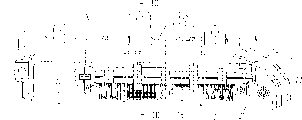
Fig. 1: the cross-sectional side elevational view of housing half shell of a clutch regulator with connector bar,
Fig. 2: the zoomed-in view of local X among Fig. 1,
Fig. 3: during the assembled connector bar along the cross-sectional view of Fig. 1 center line III-III,
Fig. 4: the cross-sectional view of connector bar after assembling is finished,
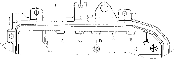
Fig. 5: housing half shell of no connector bar among Fig. 1.
Embodiment
In Fig. 1, only express one and half shells 1 that are used for the housing of forming by two housing half shells of the closed and clutch regulator that separates of automobile clutch for the reason of size, the embodiment of the device 2 that an integrated therein seal that is used to prevent to be subjected to vibrational loading is offset.The function of this clutch regulator is for example known fully by DE 197 01 793A1, therefore this is not described further.
As being clear that by Fig. 3, the sealing part relates to a sealing ring 4, and it surrounds the connector bar head 12 of a connector bar 14 6 that stretch out by the aperture in the roof 8 of housing half shell 1, that narrow down to aperture 6 by stage 10.Sealing ring 4 is clamped between the interior peripheral edge in aperture 6 of the stage 10 of connector bar 14 and housing half shell 1, is used for the sealing of the relative peripheral environment in enclosure interior space thus.This roof 8 is provided with the aperture 6 that is used for connector bar head 12, and connector bar 14 preferably is maintained on the limit of housing half shell 1, is connected on relative its vertically extending sidewall 16 at this roof 8 on this limit.
Make connector bar 14 remain on the interior peripheral edge in aperture 6 of housing half shell 1 internally and thus also precompressed confining force or the precompression of sealing ring 4 produce by clamping device, according to a preferred implementing form, this clamping device comprises clamping plate 18 that are parallel to connector bar 14 longitudinal extensions, and the end sections ground encapsulation of the maintenance bolt 20 that is configured to right-angle bending of these clamping plate two end faces (Fig. 1) of connector bar 14.
Shown in the cross section of the local X that amplifies among Fig. 2, the part of maintenance bolt 20 its bottom surfaces of usefulness of clamping plate 18 is bearing on two hooks of stretching downwards abreast from housing half shell 1 roof 8 22, and these two hooks are arranged with being mutually symmetrical.On the other hand, keep bolt 20 in groove 24, to be directed to with also flushing, this groove opens wide and is arranged on the end face of connector bar 14 to hook 22, like this, perpendicular to the longitudinal extension of groove 24 and with Fig. 3 in the power of precompression adverse effect of the sealing ring 4 shown in the dotted arrow can be received by the hook 22 of housing half shell 1.
As shown in Figure 3, clamping plate 18 have a latch 26 that stretch out towards the side of connector bar 14 from it, best and its median plane coplane ground extends, and this latch dwindles towards its wedge shape ground, end.This latch 26 can be inserted in the transverse holes 28 of connector bar 14, and this transverse holes is preferably extended transverse to the precompressed direction of sealing ring 4, and wherein direction of insertion is represented by horizontal arrow in Fig. 3.The transverse holes 28 of connector bar 14 for example is configured to open-work.
Because clamping plate 18 can be bearing in the maintenance bolt 20 at its both ends on the hook 22 of housing half shell 1, therefore when latch 26 is inserted in the transverse holes 28 of connector bar 14, connector bar 14 is reached on its sealing ring 4 that reclining, applied a precompression thus perpendicular to the direction of insertion of latch 26.Because the wedge structure of latch is along with the increasing precompression increase of insertion depth.For example, shown in Figure 4 reach given precompression when inserting terminal location fully when latch 26 is in, at this moment Sealing shield ring 30 backstops of latch 26 are on the edge of the transverse holes 28 of connector bar 14.
Since by the precompression that latch 26 produces, reaction force of effect on the maintenance bolt 20 of clamping plate 18, and this power makes and keeps bolt to be pressed on the hook 22 of housing half shell 1.Avoid shifting out of clamping plate 18 by this precompression and the 2nd housing half shell spacing.
Because precompression also acts on the sealing ring 4 between 6 edges, aperture of the stage 10 of connector bar 14 and housing half shell 1, and, thereby sealed reliably by the relative peripheral environment in interior space of the clutch regulator of two housing half shells sealing because but sealing ring 4 is made of a kind of material based on given precompression elasticity and/or plastic deformation.
As shown in Figure 4, the side that deviates from the connector bar 14 of clamping plate 18 is fixed on the printed circuit board (PCB) 32, and the latter can be bearing on the sidewall 16 of housing half shell 1.Therefore connector bar 14 is being pressed on the sidewall 16 of housing half shell 1 by the clamping plate 18 that are clamped on the hook 22 on the direction of the precompression of vertical seal ring 4.
For fear of laterally being offset, it is provided with the stop surface that is substantially perpendicular to the precompression directive effect at vibrational loading lower sealing ring 4.According to the preferred embodiment, on the one hand, these stop surfaces comprise the stopping dam 34 that is molded on the clamping plate 18, and these stopping dams are provided with spacing and with the contact of the outer peripheral face of sealing ring 4 or with relative its layout in very little gap one by one along its longitudinal extension direction.On the other hand, be provided with the supporting rib 36 on the sidewall 16 that is configured in housing half shell 1, they are parallel to connector bar 14 and are arranged in a line with a determining deviation and front and back, and as being clear that by Fig. 5, housing half shell 1 shown in it does not have connector bar 14.If although sealing ring 4 has the precompression that acts on it now,, then it is remained on its position by these stop surfaces 34,36 because vibration is tending towards being offset in the plane perpendicular to the precompression direction.
Can replace only is the stop surface 34,36 that section ground is provided with along the sealing ring periphery, according to another form of implementation of the present invention, these stop surfaces can be made closed face.
Claims (8)
1. prevent to be subjected to the device of the seal skew of vibrational loading, the sealing part is maintained between two parts that clamped mutually by clamping device, housing half shell (1) that these two parts are a connector bar (14) and an automobile clutch adjuster, wherein, this device is included in and works on the plane perpendicular to the precompression direction, the stop surface (34 that is used for seal (4), 36), these stop surfaces are configured in clamping device (18 at least in part, 26) on, it is characterized in that: clamping device comprises that at least one is bearing in the latch (26) on housing half shell (1), this latch dwindles towards its free end wedge shape ground and can be inserted into like this in the hole (28) perpendicular to the extension of precompression direction of connector bar (14), that is: insertion depth is bigger, and the precompression that is applied on connector bar (14) and the seal (4) is bigger.
2. according to the device of claim 1, it is characterized in that: a roof (8) is provided with the aperture (6) that is used for connector bar head (12), connector bar (14) is fixed on the limit of housing half shell (1), this roof (8) on this limit be connected one with respect to the vertically extending sidewall of this roof (16) on.
3. according to the device of claim 2, it is characterized in that: the sealing part comprises a sealing ring (4) around connector bar head (12), and the sealing ring is clamped between the interior peripheral edge in aperture (6) of roof (8) of the stage (10) of connector bar (14) and housing half shell (1).
4. according to the device of claim 3, it is characterized in that: when latch (26) is in a terminal location, reach given precompression, in Sealing shield ring (30) backstop of latch (26) on this terminal location on the edge of the transverse holes (28) of connector bar (14).
5. according to the device of claim 4, it is characterized in that: clamping device also comprises clamping plate (18), latch (26) stretches out from the side towards connector bar (14) of clamping plate (18), the effect of clamping plate opposing precompression is bearing on housing half shell (1) in this wise, promptly respectively be provided with one and keep bolt (20) at the two ends of clamping plate, described maintenance bolt is inserted in the groove (24) that is configured in the connector bar (14) on the one hand, is pressed in respectively on the other hand on the hook (22) that stretches out downwards from the roof (8) of housing half shell (1).
6. according to the device of claim 5, it is characterized in that: connector bar (14) on the direction of vertical precompression by plugging on the sidewall (16) that clamping plate (18) are fixed on housing half shell (1).
7. according to the device of claim 6, it is characterized in that: described stop surface comprises the stopping dam (34) that is molded on the clamping plate (18) on the one hand, and these stopping dams separate that spacing is arranged one by one and contact or face mutually with this outer peripheral face with the outer peripheral face of sealing ring (4) along clamping plate longitudinal extension direction.
8. according to the device of claim 7, it is characterized in that: described stop surface comprises the supporting rib (36) on the sidewall (16) that is configured in housing half shell (1) on the other hand, and these supporting ribs are parallel to connector bar (14), have spacing and front and back are disposed aligned mutually.
Applications Claiming Priority (2)
| Application Number | Priority Date | Filing Date | Title |
|---|---|---|---|
| DE10023587.5 | 2000-05-13 | ||
| DE10023587A DE10023587A1 (en) | 2000-05-13 | 2000-05-13 | Device to prevent seal subject to vibration loading from drifting; has abutment surface for seal in plane perpendicular to clamp direction and partly formed in clamp devices to hold seal |
Publications (2)
| Publication Number | Publication Date |
|---|---|
| CN1429420A CN1429420A (en) | 2003-07-09 |
| CN1248370C true CN1248370C (en) | 2006-03-29 |
Family
ID=7641996
Family Applications (1)
| Application Number | Title | Priority Date | Filing Date |
|---|---|---|---|
| CNB018094325A Expired - Fee Related CN1248370C (en) | 2000-05-13 | 2001-04-05 | Device for preventing drift of seal in vibrating environment |
Country Status (10)
| Country | Link |
|---|---|
| US (1) | US6893279B2 (en) |
| EP (1) | EP1299925B1 (en) |
| JP (1) | JP2003533661A (en) |
| KR (1) | KR100828955B1 (en) |
| CN (1) | CN1248370C (en) |
| BR (1) | BR0110790A (en) |
| CZ (1) | CZ20023669A3 (en) |
| DE (2) | DE10023587A1 (en) |
| ES (1) | ES2243487T3 (en) |
| WO (1) | WO2001089039A1 (en) |
Families Citing this family (1)
| Publication number | Priority date | Publication date | Assignee | Title |
|---|---|---|---|---|
| JP6843264B2 (en) * | 2017-10-19 | 2021-03-17 | 三菱電機株式会社 | Waterproof connector and its assembly method |
Family Cites Families (10)
| Publication number | Priority date | Publication date | Assignee | Title |
|---|---|---|---|---|
| EP0223869B1 (en) * | 1985-11-21 | 1990-01-17 | C.A. Weidmüller GmbH & Co. | Arrangement of feed-through terminals |
| DE3733156C1 (en) * | 1987-10-01 | 1988-11-10 | Phoenix Elekt | Bushing terminal |
| FR2733571B1 (en) * | 1995-04-28 | 1997-06-13 | Valeo | WATERPROOF HYDRAULIC CONNECTION |
| JPH0945444A (en) * | 1995-07-28 | 1997-02-14 | Yazaki Corp | Water-proofing structure for lamp socket |
| US5785543A (en) * | 1995-12-04 | 1998-07-28 | Litton Systems, Inc. | High voltage flashlamp connector method and apparatus |
| DE19701739A1 (en) | 1997-01-20 | 1998-07-23 | Bosch Gmbh Robert | Actuator |
| DE29710984U1 (en) * | 1997-06-24 | 1997-08-21 | Festo Kg | Electrical connector device |
| DE19729096A1 (en) * | 1997-07-08 | 1998-09-24 | Bosch Gmbh Robert | Vehicle gearbox and clutch controllers using electric motors |
| US5870833A (en) * | 1997-08-06 | 1999-02-16 | Clorox Company | Balancing container finish measuring device |
| US6428368B1 (en) * | 2001-03-26 | 2002-08-06 | Pacesetter, Inc. | Side actuated lead connector assembly for implantable tissue stimulation device |
-
2000
- 2000-05-13 DE DE10023587A patent/DE10023587A1/en not_active Withdrawn
-
2001
- 2001-04-05 BR BRPI0110790-9A patent/BR0110790A/en not_active IP Right Cessation
- 2001-04-05 CN CNB018094325A patent/CN1248370C/en not_active Expired - Fee Related
- 2001-04-05 CZ CZ20023669A patent/CZ20023669A3/en unknown
- 2001-04-05 EP EP01929316A patent/EP1299925B1/en not_active Expired - Lifetime
- 2001-04-05 DE DE50106643T patent/DE50106643D1/en not_active Expired - Lifetime
- 2001-04-05 KR KR1020027014975A patent/KR100828955B1/en not_active IP Right Cessation
- 2001-04-05 WO PCT/DE2001/001322 patent/WO2001089039A1/en active IP Right Grant
- 2001-04-05 ES ES01929316T patent/ES2243487T3/en not_active Expired - Lifetime
- 2001-04-05 JP JP2001585359A patent/JP2003533661A/en active Pending
- 2001-04-05 US US10/276,147 patent/US6893279B2/en not_active Expired - Fee Related
Also Published As
| Publication number | Publication date |
|---|---|
| US6893279B2 (en) | 2005-05-17 |
| DE10023587A1 (en) | 2001-11-15 |
| KR100828955B1 (en) | 2008-05-13 |
| BR0110790A (en) | 2007-10-23 |
| ES2243487T3 (en) | 2005-12-01 |
| EP1299925A1 (en) | 2003-04-09 |
| CZ20023669A3 (en) | 2003-06-18 |
| EP1299925B1 (en) | 2005-06-29 |
| CN1429420A (en) | 2003-07-09 |
| WO2001089039A1 (en) | 2001-11-22 |
| JP2003533661A (en) | 2003-11-11 |
| DE50106643D1 (en) | 2005-08-04 |
| US20040092161A1 (en) | 2004-05-13 |
| KR20030005331A (en) | 2003-01-17 |
Similar Documents
| Publication | Publication Date | Title |
|---|---|---|
| CN105580214B (en) | Module housing for electronic building brick | |
| CN1993868B (en) | Connector | |
| JP5260198B2 (en) | Inverter-integrated electric compressor | |
| CN101911397A (en) | Board-to-board connector | |
| CN1161867C (en) | Frame corner connector | |
| CN1866654A (en) | Mounting bracket structure | |
| CN101566214A (en) | Cable protection and guide device | |
| CN1037557C (en) | Alignment member for use with surface mount contacts | |
| CN1697268A (en) | Coaxial connector for printed board | |
| CN1441516A (en) | Plane circuit connector | |
| CN1721656B (en) | Single controlling apparatus for shielding bracket | |
| CN103370227B (en) | Grommet | |
| CN1248370C (en) | Device for preventing drift of seal in vibrating environment | |
| CN1734872A (en) | Fusible link receptacle for electrical connector box | |
| CN1284277C (en) | Electric connector | |
| US20110255224A1 (en) | Electric component and pin header for such a component | |
| CN1507115A (en) | Connector for accemulator | |
| JP7185661B2 (en) | connector | |
| JP2013153586A (en) | Water cut-off structure of vehicular door | |
| KR20160033437A (en) | Housing for circuit board | |
| US11063383B2 (en) | Receptacle connector | |
| CN1115092C (en) | Electromagnetic casing screen | |
| JP5321215B2 (en) | Electromagnetic shielding gasket | |
| KR970018862A (en) | Movable connector with extension support plate | |
| CN1901283A (en) | Virtual terminal mounting structure and electromagnetic relay device |
Legal Events
| Date | Code | Title | Description |
|---|---|---|---|
| C06 | Publication | ||
| PB01 | Publication | ||
| C10 | Entry into substantive examination | ||
| SE01 | Entry into force of request for substantive examination | ||
| C14 | Grant of patent or utility model | ||
| GR01 | Patent grant | ||
| CF01 | Termination of patent right due to non-payment of annual fee |
Granted publication date: 20060329 Termination date: 20150405 |
|
| EXPY | Termination of patent right or utility model |