CN1226864C - Image sensing equipment, mask correction method, program and storage medium - Google Patents
Image sensing equipment, mask correction method, program and storage medium Download PDFInfo
- Publication number
- CN1226864C CN1226864C CNB021020280A CN02102028A CN1226864C CN 1226864 C CN1226864 C CN 1226864C CN B021020280 A CNB021020280 A CN B021020280A CN 02102028 A CN02102028 A CN 02102028A CN 1226864 C CN1226864 C CN 1226864C
- Authority
- CN
- China
- Prior art keywords
- shading correction
- image sensing
- correction coefficient
- sensing element
- lens
- Prior art date
- Legal status (The legal status is an assumption and is not a legal conclusion. Google has not performed a legal analysis and makes no representation as to the accuracy of the status listed.)
- Expired - Fee Related
Links
Images


Classifications
-
- H—ELECTRICITY
- H04—ELECTRIC COMMUNICATION TECHNIQUE
- H04N—PICTORIAL COMMUNICATION, e.g. TELEVISION
- H04N25/00—Circuitry of solid-state image sensors [SSIS]; Control thereof
- H04N25/60—Noise processing, e.g. detecting, correcting, reducing or removing noise
- H04N25/63—Noise processing, e.g. detecting, correcting, reducing or removing noise applied to dark current
-
- H—ELECTRICITY
- H04—ELECTRIC COMMUNICATION TECHNIQUE
- H04N—PICTORIAL COMMUNICATION, e.g. TELEVISION
- H04N23/00—Cameras or camera modules comprising electronic image sensors; Control thereof
- H04N23/60—Control of cameras or camera modules
- H04N23/66—Remote control of cameras or camera parts, e.g. by remote control devices
- H04N23/663—Remote control of cameras or camera parts, e.g. by remote control devices for controlling interchangeable camera parts based on electronic image sensor signals
Abstract
This invention has as its object to eliminate sensitivity nonuniformity on the plane of an image sensing element irrespective of exchange of a lens. To achieve this object, in an image sensing apparatus which has an image sensing element and can exchange a lens, a memory stores shading correction coefficients respectively corresponding to pixels in a two-dimensional matrix on the plane of the image sensing element, and a correction device makes a correction calculation of pixel data read out from each pixel of the image sensing element by extracting the shading correction coefficient associated with the corresponding pixel from those stored in the memory.
Description
Technical field
The present invention relates to image sensing equipment, blackspot (shading) bearing calibration, program and storage medium, more particularly, relate to and a kind ofly adopt the image sensing equipment of interchangeable image sensing lens, a kind of shading correction method thereof that is applied to this image sensing equipment, and a kind of storage medium that is used for the program of this shading correction method thereof of storage implementation.
Background technology
Figure 10 block diagram is represented the structure of the interchangeable Digital Still Camera of a routine conventional lenses.
With reference to Figure 10, camera operation switch (switch) 43 comprises a main SW and discharges SW.When camerist operation camera operation switch 43, total control circuit 44 detects the change of camera operation switch 43 states, and provides power supply to other modules.
Object image in the photographic film scope is formed on the image sensing unit 34 by main camera optical system 33, thereby image sensing unit 34 exports the signal of telecommunication to A/D converter 35.Converted to set digital signal successively for each pixel signal of telecommunication, then digital signal is sent to treatment circuit 36.Treatment circuit 36 produces R, G and B color signal according to pixel data, and for per frame period property ground bear results is transferred to video memory 41 via storage control 37 when camerist is taken a picture operation in advance.Monitor scope 42 makes view finder demonstration etc. according to the data that transfer to video memory 41.
On the other hand, when camerist has been taken a picture operation on camera operation switch 43, in response to being stored in the frame memory 38 from the control signal of total control circuit 44, total control circuit 44 is used to survey the change of the state of camera operation switch 43 from a frame pixel data of treatment circuit 36 output.Then, the data in the frame memory 38 are stored controller 37 and working storage 39 is compressed into set compressed format, and compression result is stored in the external memory 40.Notice that external memory 40 comprises that nonvolatile memory is such as flash memory etc.
For according to pictorial data displayed image being shot, storage control 37 will be stored in packed data in the external memory 40 for corresponding photograph pixel and de-compress into and be normal data, and with the decompression result transmission to video memory 41.Monitor scope 42 makes view finder demonstration etc. according to the data that transfer to video memory 41.
The image sensing element that is used in the commutative digital camera of conventional lenses adopts the lenticule shown in Figure 11 A and the 11B for the corresponding photosensitive pixels of image sensing element, so that improve the luminous sensitivity of each pixel.
Figure 11 A and 11B represent to depend on microlens location and produce the blackspot principle of (depending on the spatial sensitivity inhomogeneities from the incidence angle of the incident light of lens) from relation between the incident angle of light of lens.With reference to Figure 11 A and 11B, 20 expressions of number mark are as the lens of field lens; Number mark 21 expression lenticules; The sensitization part of number mark 22 presentation image sensing elements.
Because lenticule 21 is arranged on the corresponding sensitization part 22 of image sensing element pixel, so have narrower effective sensing region even work as each sensitization part 22 of image sensing element, edge light also can focus on the sensitization part 22 effectively.
Yet when the light of scioptics 20 almost vertically was radiated on the sensitization part 22 of image sensing element, shown in Figure 11 A, incident ray focused on the sensitization part 22 of image sensing element and can not cause any serious problem.Yet, when the light of scioptics 20 is radiated on the sensitization part 22 of image sensing element obliquely, shown in Figure 11 B, because the optical relation between lens 20 and the lenticule 21, each the sensitization part on the zone of having only some incident ray to be incident on to leave lens 20 optical axises (periphery of image sensing element).
This luminous flux descends and is commonly referred to as white light blackspot (white shading).Along with pixel location on the image sensing element leaves fartherly apart from the optical axis of lens 20, this phenomenon is remarkable increasingly.
The method that is used for the white light blackspot of lenticule 21 combination results on correcting lens 20 and the image sensing element for example is disclosed in the open No.6-197266 of Japan Patent.In the method, in the built-in storage of lens, store the shading correction data in advance, and when taking a picture, read.Reference voltage according to the data generation A/D conversion circuit of being read converts the analog sensing picture intelligence to digital signal according to this reference voltage, thereby realizes shading correction.
When the commutative digital camera of traditional lens adopt with traditional SLR silver halide film camera in during identical optical system (for example commutative lens combination), its needed image sensing size of component is more much bigger than the image sensing size of component of the digital camera that does not adopt this kind optical system.
Yet in this large scale image sensing element, the incidence angle of image sensing element periphery light depends on lens and becomes bigger.In the case, owing to the foozle of colour filter in microlens location, the chip, device architecture of image sensing element or the like can cause sensitivity inhomogeneities (blackspot), i.e. the sensitivity of the image sensing element periphery that incidence angle change is big descends.This problem below will be illustrated.
Shown in Figure 11 A and 11B, nearest solid-state image sensing element comprises that being used for that incident light is focused on photodiode (the sensitization part 22 of image sensing element) goes up to improve the lenticule 21 of sensitivity.Yet when the incidence angle of incident light became big, the incident light that is reflected by lenticule 21 focused on the position of leaving each photodiode center, thereby has reduced the sensitivity of this pixel.
Traditionally, can obtain to consider that the characteristic owing to the lens that form image makes the increase of the incidence angle of incident light on the image sensing element periphery carry out the image sensing equipment of shading correction, as disclosed among the open No.6-197266 of Japan Patent.Yet in can the image sensing equipment system of exchange lens, the incidence angle characteristic of the incident ray on the image sensing element sharply changes when exchange lens, thereby can not accurately carry out shading correction.
Even when need not exchange lens adopting einzel lens, if lens are zoom lens, then since the emergent pupil position of lens when the photograph angle of visual field changes or at lens, can change during to the object focus of different distance, so the incidence angle of incident light can change on the image sensing element periphery, thereby can not accurately carry out shading correction.
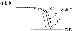
In addition, Figure 12 A to 12C represents the generation principle of the color blackspot that causes owing to the reflective cutoff filter of multi-layered type.Figure 12 A represents the spectral transmissions characteristic that reflective cutoff filter changes with incidence angle.Figure 12 B represents that an example comprises the spectral sensitivity characteristic of the image sensing element of colour filter in the chip, and Figure 12 C represents the sensitivity of red color filter pixel.Figure 12 A to 12C illustration have an image sensing element of colour filter in the RGB primary colors type chip.Wavelength on attention Figure 12 A abscissa has identical order of magnitude dimension with the wavelength on Figure 12 B abscissa.
Suppose to be incident in the image sensing element with spectral sensitivity characteristic shown in Figure 12 B by light beam with cutoff filter of spectral transmissions characteristic shown in Figure 12 A.In the case, from Figure 12 A and 12B as can be seen, the spectral transmissions characteristic of cutoff filter is irrelevant with incidence angle, still closely related with incidence angle in the wave-length coverage of red color filter in the wave-length coverage of blue and green color filter.From the product representation of the photobehavior of the signal of image sensing element output by the spectral sensitivity characteristic of the spectral transmissions characteristic of cutoff filter and image sensing element.Therefore, when the incidence angle of incident light was big, sensitivity can take place and descend in the pixel with red color filter, thereby can produce the color blackspot, be that the sensitivity meeting that only has the pixel of red color filter on the image sensing element periphery descends, shown in Figure 12 C.
Summary of the invention
The present invention considers the problems referred to above and makes, thereby its purpose is to provide a kind of image sensing equipment, shading correction method thereof, and storage medium, can eliminate the sensitivity inhomogeneities on the image sensing element, and no matter whether lens exchange in the image sensing equipment of the commutative lens of employing.
Another object of the present invention is to provide a kind of image sensing equipment, shading correction method thereof, and storage medium, can proofread and correct the color blackspot that produces in the particular color passage of image sensing element.
In order to solve foregoing problems and to realize above-mentioned purpose, be characterised in that following setting according to the image sensing equipment of first aspect present invention.
Also promptly, a kind of image sensing element and image sensing equipment that can exchange lens of comprising, comprising: extraction element is used for extracting the information that is included in lens; Shading correction coefficient deriving means is used for obtaining the shading correction coefficient about two orthogonal directions on the image sensing element plane based on the information by described extraction element extraction; And means for correcting, be used for selecting two shading correction coefficients from the shading correction coefficient that described shading correction coefficient deriving means obtains according to the address of the corresponding pixel of described two orthogonal directions, and use selected two shading correction coefficients that the pictorial data of the corresponding pixel output of image sensing element is carried out correction calculation, wherein, the information that is included in the lens is the emergent pupil positional information, and described shading correction coefficient deriving means is based on the shading correction coefficient of described emergent pupil positional information calculation about two orthogonal directions on the image sensing element plane.
Image sensing equipment according to second aspect present invention is characterised in that following setting.
Also promptly, a kind of image sensing element and image sensing equipment that can exchange lens of comprising comprises storage device, is used to store the shading correction coefficient corresponding respectively with the pixel of image sensing element; And means for correcting, be used for by extract the shading correction coefficient related from the shading correction coefficient that is stored in described storage device with corresponding pixel, the pixel data of reading from each pixel of image sensing element is carried out correction calculation, wherein said means for correcting is according to the shading correction coefficient that is stored in the described storage device, to be subjected to not transmission particular range of wavelengths and be inserted in lens with the image sensing element between the pixel that influences of colour filter and the pixel that not influenced by this colour filter proofread and correct independently.
Shading correction method thereof according to first aspect present invention is characterised in that following setting.
Also be, a kind of shading correction method thereof that is applied to comprise image sensing element and image sensing equipment that can exchange lens, comprise storing step, shading correction coefficient storage that will be corresponding respectively with the two-dimensional matrix pixel on the image sensing element plane is in a storage device; And aligning step, be used for by extract the shading correction coefficient related from the shading correction coefficient that is stored in described storage device with corresponding pixel, the pixel data of reading from each pixel of image sensing element is carried out correction calculation, wherein said storing step comprises the shading correction coefficient storage is divided into the shading correction coefficient in described storage device simultaneously along the step of two orthogonal direction components on the image sensing element plane, and described aligning step comprises that the corresponding pixel addresses according to described both direction extracts two shading correction coefficients from the shading correction coefficient that is stored in described storage device, and will multiply by these two shading correction coefficients that extracted from the pixel data that corresponding pixel is read successively to proofread and correct the step of pixel data.
Shading correction method thereof according to second aspect present invention is characterised in that following setting.
Also promptly, a kind of shading correction method thereof that is applied to comprise image sensing element and image sensing equipment that can exchange lens comprises: extraction step, extract the information that is included in the lens; Shading correction coefficient obtaining step based on the information of extracting at described extraction step, obtains the shading correction coefficient about two orthogonal directions on the image sensing element plane; And aligning step, two shading correction coefficients are selected in address according to the corresponding pixel of described two orthogonal directions from the shading correction coefficient that described shading correction coefficient obtaining step obtains, and use selected two shading correction coefficients that the pictorial data of the corresponding pixel output of image sensing element is carried out correction calculation, wherein, the information that is included in the lens is the emergent pupil positional information, and described shading correction coefficient deriving means is based on the shading correction coefficient of described emergent pupil positional information calculation about two orthogonal directions on the image sensing element plane.
Performance of program according to the present invention is following setting.
Also promptly, a kind of program is used to make computer-implemented described shading correction method thereof.
Storage medium according to the present invention is characterised in that following setting.
Also promptly, a kind of storage medium stores described program with being used for computer-readable.
According to the explanation of the following preferred embodiment of the present invention, it should be apparent to those skilled in the art that other purposes and advantage outside above-mentioned purpose and the advantage.With reference to accompanying drawing, and accompanying drawing constitutes the part of specification and has shown an example of the present invention in specification.Yet this example can not limit various embodiment of the present invention, thereby also should be with reference to the claim after the specification to determine scope of the present invention.
Description of drawings
Fig. 1 represents the block diagram of the structure of the image sensing equipment (Digital Still Camera) according to the embodiment of the invention;
Fig. 2 A to 2D represents the color interpolation processing;
Fig. 3 A and 3B represent the shading correction coefficient, are used to proofread and correct because the blackspot that lens and image sensing component arrangement textural association produce;
Fig. 4 A to 4C represents the shading correction coefficient in the embodiment of the invention, the plane of Fig. 4 A presentation image sensing element wherein, and Fig. 4 B represents the horizontal component of shading correction coefficient, Fig. 4 C represents the vertical component of shading correction coefficient;
Fig. 5 represents the light path from lens to the image sensing element;
Fig. 6 represents the sensitivity curve with respect to incidence angle θ;
X-and the Y-component of image height d on Fig. 7 presentation image sensing element plane;
Fig. 8 A to 8E represents RGB primary colours Bayer color filter matrix, and corresponding to the shading correction coefficient of this matrix;
Fig. 9 represents the flow chart by the acquired signal HSEL of address recognition circuit execution and VSEL output procedure order;
Figure 10 represents the block diagram of a routine structure of traditional commutative Digital Still Camera of lens;
The principle that Figure 11 A and 11B represent to depend on microlens location and produce blackspot from relation between the incident angle of light of lens; And
Figure 12 A to 12C represents the principle of the color blackspot that causes owing to the reflective cutoff filter of multi-layered type.
Embodiment
The preferred embodiments of the present invention are described with reference to the accompanying drawings.
Fig. 1 represents the block diagram of the structure of the image sensing equipment (Digital Still Camera) according to the embodiment of the invention.This image sensing equipment can transform lens.
With reference to Fig. 1, number mark 1 expression master control CPU is used to control whole camera; Number mark 2 expression outgoing pupil location detectors; The commutative lens of number mark 3 expressions.Commutative lens 3 comprise the emergent pupil positional information, and detector 2 detection packet are contained in the emergent pupil positional information in the commutative lens 3, produce coded message by the correcting detection value, and export institute's generation information to CPU1.
The emergent pupil positional information is used to calculate the shading correction coefficient, and the back will describe in detail.Before calculating, the emergent pupil positional information is proofreaied and correct according at least one of zoom position, focal position, image height and the aperture value of commutative lens 3.More particularly, the emergent pupil position is generally by distance expression on the optical axis between lens and the image sensing element, and along with the change of zoom or focal position synchronous change.Know that equally the emergent pupil position can change a little when changing when image height (distance between putting on the position of concern pixel and the optical axis) on image sensing element plane.In addition, when aperture value changed, the ranges of incidence angles that is radiated at light beam on the concern pixel of image sensing element can change.Because changing when calculating the shading correction coefficient, these occur with errors of form, so according at least one of zoom position, focal position, image height and the aperture value of commutative lens 3 the emergent pupil positional information is proofreaied and correct, to obtain accurate shading correction.
The reflective cutoff filter of number mark 4 expression multi-layered types; Number mark 5 presentation image sensing elements.Image sensing element 5 for example comprises for example CCD etc. of charge-transfer device.Object image is formed on the image sensing element 5 by commutative lens 3, and image sensing element 5 is read the electric charge that gathers as the imaging result successively to each pixel then, and it is exported on the CDS/AGC circuit 6.CDS/AGC circuit 6 is suppressed in the image sensing element 5 noise contribution that the produces noise etc. of for example resetting, and then charge signal is amplified to proper level, and exports these signals to A/D change-over circuit 7.A/D change-over circuit 7 will become numerical data corresponding to the object brightness data transaction of the above-mentioned quantity of electric charge.Owing to be bonded on the image sensing element 5 in order to the optical colour filter that produces color signal (for example R, G and B signal), so represent respective color successively from the output signal of image sensing element 5.
Drivers of number mark 8 expressions, being used for each element to image sensing element 5 provides and gathers the required electric energy of electric charge on it.More particularly, driver 8 provides electric energy by according to the timing signal that sends from clock generator 9 image sensing element 5 being carried out two-dimensional scan.
Clock generator 9 provides horizontal-drive signal HD and vertical synchronizing signal VD to address production electric circuit 10, and address production electric circuit 10 produces address signal according to these synchronizing signals.
12 to 15 expressions of number mark are used for the memory that the required correction data of sensitivity correction (shading correction) of image sensing element 5 (back will be illustrated) is carried out in storage: 12 expressions of number mark are used to store the H memory H1 of the first level correction data; 13 expressions of number mark are used to store the H memory H2 of the second level correction data; 14 expressions of number mark are used to store the V memory V1 of the first vertical correction data; And 15 expressions of number mark are used to store the V memory V2 of the second vertical correction data.
The pixel data that has passed through sensitivity correction (shading correction) and exported from mlultiplying circuit (MUL2) 19 generally is sent to the treatment circuit (not shown), passes through black level (dark level) correction, γ conversion and color interpolation then and handles.Result is stored in the memory (not shown).
Fig. 2 A to 2D represents the color interpolation processing.The PEL (picture element) matrix of Fig. 2 A presentation image sensing element 5, Fig. 2 B represents G (green) interpolation colour filter, and Fig. 2 C represents R (redness)/B (blueness) interpolation colour filter, and Fig. 2 D represents the PEL (picture element) matrix after the interpolation processing.The color filter matrix that is used in the image sensing element is common Bayer matrix, comprises an alternate matrix that is used for G, shown in Fig. 2 B and a linear order matrix that is used for R/B, shown in Fig. 2 C.
Under the situation of one chip image sensing element, because not all pixel all has RGB information, so produce the RGB colouring information by utilizing 3 * 3 matrixes shown in Fig. 2 B and the 2C to carry out interpolation operation all picture element places on the image sensing element usually.Describe this processing below in detail.
For example, in order to produce the G interpolated signal of pixel a shown in Fig. 2 A, will be that the data of pixel multiply by interpolation colour filter coefficient around the pixel a on boundary and eight with dotted line a1, and with its product accumulation.In the G interpolation colour filter shown in Fig. 2 B, with the corresponding coefficient of G (green) pixel in the dotted line a1 be " 1 " in pixel a position, and be " 0 " at the pixel location place in four corners.Therefore, the data of pixel a directly become the G interpolated signal.
On the other hand, for example, in order to produce the G interpolated signal of pixel b shown in Fig. 2 A, will be that the output level data of pixel multiply by G interpolation colour filter coefficient around the pixel b on boundary and eight with dotted line b1, and with its product accumulation.In the case, in the G interpolation colour filter shown in Fig. 2 B, with the corresponding coefficient of G (green) pixel in the dotted line b1 pixel b upper and lower, a left side and right adjacent position be 0.25.Therefore, the G interpolated signal of pixel b for will be described upper and lower a, left side and right adjacent position multiplication afterwards with the value of its product accumulation gained.In other words, G interpolated signal in the case is described upper and lower a, left side and the mean value of right adjacent position brightness data.
In kind, adopt with the R/B interpolation colour filter that G interpolation colour filter has different coefficients and determine R/B interpolated signal for all R (redness)/B (green) pixel.
In this way, produce R, G and B interpolated signal at last, shown in Fig. 2 D for all pixels.
Handle below with reference to the sensitivity correction (shading correction) that Fig. 3 A and 3B and Fig. 4 A to 4C explanation are carried out in image sensing equipment shown in Figure 1.
Fig. 3 A and 3B represent the shading correction coefficient, are used to proofread and correct because the blackspot that lens and image sensing component arrangement textural association produce.
More particularly, when the emergent pupil position quite is close to the image sensing element, and when sensitivity declines to a great extent on the periphery of image sensing element, to amplify to increase the shading correction coefficient of big image height position (periphery of image sensing element), as shown in Figure 3A from the output signal of image sensing element.On the other hand, when emergent pupil far away and on the periphery of image sensing element sensitivity descend when not too big, to amplify a little to increase the shading correction coefficient of big image height position (periphery of image sensing element) a little, shown in Fig. 3 B from the output signal of image sensing element.More particularly, emergent pupil position sensor 2 shown in Fig. 1 reads the emergent pupil positional information in the commutative lens 3, according to zoom position or focal position etc. it is proofreaied and correct, and institute's control information is sent to master control CPU1, and master control CPU1 the shading correction coefficient according to the emergent pupil positional information calculation of having proofreaied and correct.
If the strictness of shading correction coefficient determined corresponding to image height, then its must to set for the image sensing element be the concentric pattern at center, thereby make the hardware processing difficulties.Therefore, in this embodiment, set the shading correction coefficient shown in Fig. 4 A to 4C.
Fig. 4 A to 4C represents the shading correction coefficient among this embodiment.The plane of Fig. 4 A presentation image sensing element, Fig. 4 B represents the horizontal component of shading correction coefficient, Fig. 4 C represents the vertical component of shading correction coefficient.
More particularly, with the shading correction coefficient settings is that the increase along continuous straight runs has the sensitivity than the image sensing element left and right sides periphery of muting sensitivity, and with the shading correction coefficient settings is to increase the image sensing element sensitivity of periphery up and down that vertically has than muting sensitivity, make when level and vertical shading correction coefficient component multiply each other on image plane each other, can produce false correction with one heart.If sensitivity changes fully lentamente with respect to the incidence angle of image sensing element incident light, then should vacation proofread and correct with one heart to compare and fully to guarantee satisfactory accuracy with concentric correction, the change of its sensitivity is less, as shown in Figure 6 (back will be illustrated).
The method that the shading correction coefficient is divided into level and vertical component on the image sensing element below with reference to Fig. 5 to 7 explanation.
Fig. 5 represents the light path from lens to the image sensing element.With reference to Fig. 5, number mark 20 expression lens; Number mark 23 expression diaphragms.θ represents the incidence angle of light beam, and d represents to be incident on light beam on the image sensing element 5 to the distance of optical axis center, i.e. image height, and p is represented the distance on optical axis, i.e. emergent pupil position between lens 20 and the image sensing element 5.
Fig. 6 represents the sensitivity curve with respect to incidence angle θ, the X-of image height d and Y-component on the plane of Fig. 7 presentation image sensing element 5.
Suppose as shown in Figure 6 with respect to the sensitivity of image height d (incidence angle θ), and if y represent that sensitivity and θ represent incidence angle, then the blackspot characteristic can be approximated to be as minor function:
y=Atan
2θ+Btanθ+C …(1)
tanθ=d/p …(2)
Wherein A, B and C are constant, and d and p are respectively image height and emergent pupil position (distance) as mentioned above.
As shown in Figure 7, be divided into X-on image sensing element 5 planes and Y-component dcos θ ' and dsin θ ' time, can obtain to be similar to the following equation of equation (2) when having image height d with the slope of X-axis angulation θ ':
tanθx=(dcosθ′)/p …(3)
tanθy=(dsinθ′)/p …(4)
Wherein θ x and θ y are X-and the Y-component of incidence angle θ on the plane of image sensing element 5.
If adopt this tan θ x and tan θ y, then sensitivity y can be expressed as:
y=(Atan
2θx+Btanθx+C)(Atan
2θy+Btanθy+C) …(5)
This equation (5) accurately conforms to equation (1).
With reference to above-mentioned equation (5), level and vertical correction formula are made as:
(Atan
2θx+Btanθx+C)
-1 …(6)
(Atan
2θy+Btanθy+C)
-1 …(7)
To multiply by updating formula (6) and (7) from the dateout of image sensing element corresponding pixel, calculate horizontal shading correction data H (i) and vertical shading correction data V (j).
Calculate level and vertical shading correction coefficient according to updating formula (6) and (7) for each pixel, and the CPU1 of master control shown in Fig. 1 with these coefficient storage with H memory (H1) 12 and V memory (V1) 14 in the corresponding address location of each pixel location.
In this way, adopt a sub-level and vertical shading correction coefficient, the blackspot that is caused producing by optical relation between lens 20 and the lenticule 21 is proofreaied and correct for the output of a frame image sensing element 5, and no matter performance of colour filter or the like.That is to say, in structure shown in Figure 1, mlultiplying circuit (MUL1) 18 is used for each the pixel dateout from 7 outputs of A/D change-over circuit be multiply by the horizontal shading correction data corresponding with pixel location, to carry out level correction, mlultiplying circuit (MUL2) 19 will multiply by the vertical shading correction data corresponding with pixel location from the output of multiplication circuit 18, thereby realize the shading correction for the output of a frame image sensing element 5.
As mentioned above, in the commutative image sensing equipment of lens, lens store the emergent pupil positional information, and the emergent pupil positional information calculation shading correction coefficient of lens carried out shading correction when the utilization of image sensing equipment main body was taken a picture.In this way, even when lens are exchanged, also can carry out shading correction satisfactorily.
Because the blackspot that is produced by lens and image sensing component arrangement textural association depends on the incidence angle that is incident on the light beam on the image sensing element, if, then can calculate the shading correction amount so detect the incidence angle that is radiated at incident beam on this pixel at the concern pixel location place of image sensing element.That is to say,, then can calculate incidence angle, thereby can calculate the shading correction amount if can obtain to pay close attention to the image height at pixel place and the emergent pupil position of lens.At this moment, if commutative lens store the emergent pupil positional information, and calculate image height by the image sensing equipment main body, then can accurately proofread and correct by the optical characteristics of lens and the blackspot that particular combinations caused of image sensing element, and irrelevant with the combination of commutative lens and image sensing equipment main body.
According at least one of described zoom position, focal position, image height and aperture value the emergent pupil positional information of lens is proofreaied and correct, use it for and calculate the shading correction coefficient.Therefore can improve the shading correction precision.
The following describes the method for the color blackspot that optical condition produced of the device architecture that is used to prevent to depend on image sensing element 5 and lens 20 (commutative lens 3).
If adopt the reflective cutoff filter 4 of multi-layered type before the image sensing element 5, as shown in Figure 5, and image sensing element 5 comprises the RGB primary colours Bayer colour filter shown in Figure 12 B, then because to the dependence of the incidence angle of the characteristic of cutoff filter spectral transmissions shown in Figure 12 A, the sensitivity with pixel of red color filter greatly depends on incidence angle.Reason has only produced sizable blackspot in red channel for this reason, and shown in Figure 12 C, and the blackspot that produces in other passages is compared with red channel and can be ignored.
This color blackspot that is produced by the combination of the optics of cutoff filter 4 and commutative lens 3 becomes more remarkable along with the increase of the incidence angle of cutoff filter 4 periphery incident lights, because the emergent pupil position of commutative lens 3 is more near image sensing element 5.
Fig. 8 A to 8E represents RGB Bayer color filter matrix and corresponding to the shading correction coefficient of this matrix.Fig. 8 A represents RGB Bayer color filter matrix, Fig. 8 B represents and corresponding shading correction coefficient H1 (i) and the H2 (i) of RGB Bayer colour filter first row, Fig. 8 C represents and corresponding shading correction coefficient H1 (i) and the H2 (i) of RGB Bayer colour filter second row, Fig. 8 D represents and corresponding shading correction coefficient V1 (j) and the V2 (j) of RGB Bayer colour filter first row, and Fig. 8 E represents shading correction coefficient V1 (j) corresponding with RGBBayer colour filter secondary series and V2 (j).
Because RGB primary colours Bayer colour filter has the matrix shown in Fig. 8 A, so G and R for example alternately appear in first horizontal line (first row), be positioned at the output sensitivity that the output sensitivity of counting the pixel (G) of each odd positions from left end is different from the pixel (R) that is positioned at each even number position.That is to say that the output with each pixel of R colour filter is lower than the output that periphery has the pixel of G colour filter significantly.Reason has been set shading correction coefficient H1 (i) shown in Fig. 8 B and H2 (i) for this reason.Shading correction coefficient H1 (i) is applied to have the output of the pixel of R colour filter, and is stored in the H memory (H1) 12 of Fig. 1.On the other hand, shading correction coefficient H2 (i) is applied to have the output of the pixel of G colour filter, and is stored in the H memory (H2) 13 of Fig. 1.
Because B and G alternately appear in RGB primary colours Bayer colour filter second horizontal line (second row), be similar to identical with the output sensitivity of the pixel that is positioned at each even number position (G) so be positioned at the output sensitivity of counting the pixel (B) of each odd positions from left end.Reason has been set identical blackspot correction coefficient H1 (i) shown in Fig. 8 C and H2 (i) for this reason.Shading correction coefficient H1 (i) is applied to have the output of the pixel of B colour filter, and is stored in the H memory (H1) 12 of Fig. 1.On the other hand, shading correction coefficient H2 (i) is applied to have the output of the pixel of G colour filter, and is stored in the H memory (H2) 13 of Fig. 1.
In first vertical line (first row) of RGB primary colours Bayer colour filter, because G and B alternately occur, be similar to identical from the output sensitivity of the pixel (G) of last each odd positions of terminal number with the output sensitivity of the pixel that is positioned at each even number position (B) so be positioned at.Reason has been set identical blackspot correction coefficient V1 (j) shown in Fig. 8 D and V2 (j) for this reason.Shading correction coefficient V1 (j) is applied to have the output of the pixel of G colour filter, and is stored in the V memory (V1) 14 of Fig. 1.On the other hand, shading correction coefficient V2 (j) is applied to have the output of the pixel of B colour filter, and is stored in the V memory (V2) 15 of Fig. 1.
On the other hand, because R and G alternately appear in second vertical line (secondary series) of RGB primary colours Bayer colour filter, so be positioned at the output sensitivity that is different from the pixel (G) that is positioned at each even number position from the output sensitivity of the pixel (R) of last each odd positions of terminal number.That is to say that the output with each pixel of R colour filter is lower than the output that periphery has the pixel of G colour filter significantly.Reason has been set shading correction coefficient V1 (j) shown in Fig. 8 E and V2 (j) for this reason.Shading correction coefficient V1 (j) is applied to have the output of the pixel of R colour filter, and is stored in the V memory (V1) 14 of Fig. 1.On the other hand, shading correction coefficient V2 (j) is applied to have the output of the pixel of G colour filter, and is stored in the V memory (V2) 15 of Fig. 1.
In this way, set and stored the shading correction coefficient, will multiply by the corresponding shading correction coefficient of reading according to the two-dimensional address of paying close attention to pixel location from each pixel brightness data of image sensing element 5.Below with reference to Fig. 9 this processing procedure is described.
Fig. 9 represents the flow chart by the acquired signal HSEL of address recognition circuit 11 execution and VSEL output procedure order.
Whether vertical (row) direction address of RGB primary colours Bayer colour filter of the concern pixel two-dimensional address that sends from address production electric circuit 10 in step S1 check is even number.And whether RGB primary colours Bayer colour filter level (OK) the direction address of the concern pixel two-dimensional address that sends from address production electric circuit 10 in step S2 and S7 check is even number.
After this check, if paying close attention to vertical (row) direction address of the RGB primary colours Bayer colour filter of pixel two-dimensional address is odd number (being the odd-numbered line of two-dimensional image sensing element matrix), and level (OK) direction address is odd number (being the odd column of two-dimensional image sensing element matrix), then flow process proceeds to step S3, and address recognition circuit 11 is set at L level (0 level) with acquired signal HSEL.Consequently, selector 16 will be sent to mlultiplying circuit (MUL1) 18 from the shading correction coefficient H1 (i) of H memory (H1) 12 outputs.
At step S4, address recognition circuit 11 is set at L level (0 level) with acquired signal VSEL.Consequently, selector 17 will be sent to mlultiplying circuit (MUL2) 19 from the shading correction coefficient V1 (j) of V memory (V1) 14 outputs.
Below with reference to Fig. 8 A to 8E this state is described.
That is to say, if pay close attention to pixel is to go up left G pixel 22 shown in Fig. 8 A, then mlultiplying circuit (MUL1) 18 adopt the shading correction coefficient H1 (i) shown in the solid line among Fig. 8 B (left side of H direction corresponding to horizontal direction than low address, the right side of H direction is corresponding to the higher address of horizontal direction) dateout of pixel carried out multiplication proofread and correct.On the other hand, mlultiplying circuit (MUL2) 19 adopt shading correction coefficient V1 (j) characteristic shown in the solid line among Fig. 8 D (upside of V direction corresponding to vertical direction than low address, the downside of V direction is corresponding to the higher address of vertical direction) dateout of pixel carried out multiplication proofread and correct.
On the other hand, after above-mentioned checkout procedure, if paying close attention to vertical (row) direction address of the RGB primary colours Bayer colour filter of pixel two-dimensional address is odd number (being the odd-numbered line of two-dimensional image sensing element matrix), and level (OK) direction address is even number (being the even column of two-dimensional image sensing element matrix), then flow process proceeds to step S5, and address recognition circuit 11 is set at H level (level 1) with acquired signal HSEL.Then, selector 16 will be sent to mlultiplying circuit (MUL1) 18 as the shading correction coefficient H2 (i) from H memory (H2) 13 outputs.
At step S6, address recognition circuit 11 is set at L level (level 0) with acquired signal VSEL.Thereby selector 17 will be sent to mlultiplying circuit (MUL2) 19 as the shading correction coefficient V1 (j) from V memory (V1) 14 outputs.
For example, if paying close attention to pixel is R pixel 23 shown in Fig. 8 A, then mlultiplying circuit (MUL1) 18 adopt the shading correction coefficient H2 (i) shown in the dotted line among Fig. 8 B (left side of H direction corresponding to horizontal direction than low address, the right side of H direction is corresponding to the higher address of horizontal direction) dateout of pixel carried out multiplication proofread and correct.On the other hand, mlultiplying circuit (MUL2) 19 adopt shading correction coefficient Vi (j) characteristic shown in the solid line among Fig. 8 E (upside of V direction corresponding to vertical direction than low address, the downside of V direction is corresponding to the higher address of vertical direction) dateout of pixel carried out multiplication proofread and correct.
After above-mentioned checkout procedure, if paying close attention to vertical (row) direction address of the RGB primary colours Bayer colour filter of pixel two-dimensional address is even number (being the even number line of two-dimensional image sensing element matrix), and level (OK) direction address is odd number (being the odd column of two-dimensional image sensing element matrix), then flow process proceeds to step S8, and address recognition circuit 11 is set at L level (0 level) with acquired signal HSEL.Therefore, selector 16 will be sent to mlultiplying circuit (MUL1) 18 from the shading correction coefficient H1 (i) of H memory (H1) 12 outputs.
At step S9, address recognition circuit 11 is set at H level (level 1) with acquired signal VSEL.Then, selector 17 will be sent to mlultiplying circuit (MUL2) 19 as the shading correction coefficient V2 (j) from V memory (V2) 15 outputs.
For example, if pay close attention to pixel is to go up left B pixel 24 shown in Fig. 8 A, then mlultiplying circuit (MUL1) 18 adopt the shading correction coefficient H1 (i) shown in the solid line among Fig. 8 C (left side of H direction corresponding to horizontal direction than low address, the right side of H direction is corresponding to the higher address of horizontal direction) dateout of pixel carried out multiplication proofread and correct.On the other hand, mlultiplying circuit (MUL2) 19 adopt shading correction coefficient V2 (j) characteristic shown in the solid line among Fig. 8 D (upside of V direction corresponding to vertical direction than low address, the downside of V direction is corresponding to the higher address of vertical direction) dateout of pixel carried out multiplication proofread and correct.
After above-mentioned checkout procedure, if paying close attention to vertical (row) direction address of the RGB primary colours Bayer colour filter of pixel two-dimensional address is even number (being the even number line of two-dimensional image sensing element matrix), and level (OK) direction address is even number (being the even column of two-dimensional image sensing element matrix), then flow process proceeds to step S10, and address recognition circuit 11 is set at H level (level 1) with acquired signal HSEL.Then, selector 16 will be sent to mlultiplying circuit (MUL1) 18 as the shading correction coefficient H2 (i) from H memory (H2) 13 outputs.
At step S11, address recognition circuit 11 is set at H level (level 1) with acquired signal VSEL.Thereby selector 17 will be sent to mlultiplying circuit (MUL2) 19 as the shading correction coefficient V2 (j) from V memory (V2) 15 outputs.
For example, if paying close attention to pixel is G pixel 25 shown in Fig. 8 A, then mlultiplying circuit (MUL1) 18 adopt the shading correction coefficient H2 (i) shown in the solid line among Fig. 8 C (left side of H direction corresponding to horizontal direction than low address, the right side of H direction is corresponding to the higher address of horizontal direction) dateout of pixel carried out multiplication proofread and correct.On the other hand, mlultiplying circuit (MUL2) 19 adopt the shading correction coefficient V2 (j) shown in the dotted line among Fig. 8 E (upside of V direction corresponding to vertical direction than low address, the downside of V direction is corresponding to the higher address of vertical direction) dateout of pixel carried out multiplication proofread and correct.
In this way, discern, and be that odd number or even number switch the shading correction coefficient table by insolation level and vertical address because 11 pairs of address recognition circuits are paid close attention to the two-dimensional address of pixel.Therefore, can prevent the color blackspot that the optics combination by commutative lens 3 and cutoff filter 4 shown in Figure 12 C is produced.In the above description, red blackspot is prevented.Yet the present invention is not limited to redness, but also can be applied to the color blackspot of other colors.
In this embodiment, two kinds of different shading correction coefficients have been equipped with respectively in level and vertical direction.Alternatively, also can be equipped with different shading correction coefficients with B corresponding to R, G.In addition, when adopting the compensation colour filter, can also be equipped with dissimilar shading correction coefficients in each direction.
By a storage medium is provided, wherein record the program code that on a system or equipment, to implement the software program of the foregoing description function, and the computer (perhaps CPU or MPU) by this system or equipment reads and carries out the program code that is stored in this storage medium, also can realize purpose of the present invention.
In the case, the program code that reads from storage medium itself has been implemented the function of the foregoing description, and the storage medium of the code that has program stored therein has constituted the present invention.
As the storage medium that program code is provided, can adopt for example floppy disk, hard disk, CD, magneto optical disk, CD-ROM, CD-R, tape, Nonvolatile memory card, ROM or the like.
The function of the foregoing description not only can be implemented by the mode of being carried out institute's program code read by computer, also can pass through instruction, operate by OS (operating system) operating part that moves on computers or whole actual treatment and implement according to program code.
In addition, can by write at the program code that will read from storage medium be inserted in the computer or be attached thereto the expansion board or functional expansion unit that connects after, operate the function of implementing the foregoing description by being arranged on operating parts such as CPU in this expansion board or the unit or whole actual treatment.
As mentioned above, according to the foregoing description,, also can accurately proofread and correct the blackspot that particular combinations caused by the optical characteristics of image sensing element and lens even when lens are exchanged.
And, can improve the shading correction precision.
In addition, even when lens are exchanged, also can accurately proofread and correct the color blackspot that only in a special modality, produces.
The present invention is not limited to the foregoing description, can make various variations and remodeling within the spirit and scope of the present invention.Therefore, for informing public's scope of the present invention, provided appended claim.
Claims (9)
1. one kind comprises image sensing element and image sensing equipment that can exchange lens, comprising:
Extraction element is used for extracting the information that is included in lens;
Shading correction coefficient deriving means is used for obtaining the shading correction coefficient about two orthogonal directions on the image sensing element plane based on the information by described extraction element extraction; And
Means for correcting, be used for selecting two shading correction coefficients from the shading correction coefficient that described shading correction coefficient deriving means obtains according to the address of the corresponding pixel of described two orthogonal directions, and use selected two shading correction coefficients that the pictorial data of the corresponding pixel output of image sensing element is carried out correction calculation
Wherein, the information that is included in the lens is the emergent pupil positional information, and described shading correction coefficient deriving means is based on the shading correction coefficient of described emergent pupil positional information calculation about two orthogonal directions on the image sensing element plane.
2. equipment according to claim 1, wherein said shading correction coefficient deriving means calculates the shading correction coefficient according to the image height of emergent pupil positional information and corresponding pixel.
3. equipment according to claim 2 further comprises:
Means for correcting, at least one of zoom position, focal position, image height and aperture value that is used for according to lens proofreaied and correct the emergent pupil positional information of being extracted by described extraction element, and the emergent pupil positional information of proofreading and correct is sent to described shading correction coefficient deriving means.
4. equipment according to claim 2, wherein the emergent pupil positional information is the information of the distance on optical axis between expression lens and the image sensing element.
5. equipment according to claim 2, wherein image height is to pay close attention to the position of pixel and the distance between the point on the optical axis on the image sensing element plane.
6. equipment according to claim 1, wherein said shading correction coefficient deriving means calculate independently about be subjected to not transmission particular range of wavelengths and be inserted in lens and the image sensing element between the pixel of colour filter influence and the shading correction coefficient that is not subjected to the pixel that this colour filter influences.
7. equipment according to claim 6, wherein said shading correction coefficient deriving means calculates the shading correction coefficient according to the image height of emergent pupil positional information and corresponding pixel.
8. equipment according to claim 7 further comprises:
Means for correcting, at least one of zoom position, focal position, image height and aperture value that is used for according to lens proofreaied and correct the emergent pupil positional information, and the emergent pupil positional information of proofreading and correct is sent to described shading correction coefficient deriving means.
9. shading correction method thereof that is applied to comprise image sensing element and image sensing equipment that can exchange lens comprises:
Extraction step extracts the information that is included in the lens;
Shading correction coefficient obtaining step based on the information of extracting at described extraction step, obtains the shading correction coefficient about two orthogonal directions on the image sensing element plane; And
Aligning step, two shading correction coefficients are selected in address according to the corresponding pixel of described two orthogonal directions from the shading correction coefficient that described shading correction coefficient obtaining step obtains, and use selected two shading correction coefficients that the pictorial data of the corresponding pixel output of image sensing element is carried out correction calculation
Wherein, the information that is included in the lens is the emergent pupil positional information, and described shading correction coefficient deriving means is based on the shading correction coefficient of described emergent pupil positional information calculation about two orthogonal directions on the image sensing element plane.
Applications Claiming Priority (2)
| Application Number | Priority Date | Filing Date | Title |
|---|---|---|---|
| JP009474/2001 | 2001-01-17 | ||
| JP2001009474A JP4574022B2 (en) | 2001-01-17 | 2001-01-17 | Imaging apparatus and shading correction method |
Publications (2)
| Publication Number | Publication Date |
|---|---|
| CN1366423A CN1366423A (en) | 2002-08-28 |
| CN1226864C true CN1226864C (en) | 2005-11-09 |
Family
ID=18876955
Family Applications (1)
| Application Number | Title | Priority Date | Filing Date |
|---|---|---|---|
| CNB021020280A Expired - Fee Related CN1226864C (en) | 2001-01-17 | 2002-01-17 | Image sensing equipment, mask correction method, program and storage medium |
Country Status (4)
| Country | Link |
|---|---|
| US (1) | US6937777B2 (en) |
| EP (1) | EP1227669B1 (en) |
| JP (1) | JP4574022B2 (en) |
| CN (1) | CN1226864C (en) |
Cited By (1)
| Publication number | Priority date | Publication date | Assignee | Title |
|---|---|---|---|---|
| CN104205818A (en) * | 2011-12-28 | 2014-12-10 | 富士胶片株式会社 | Imaging device, image correction method, interchangeable lens, and imaging device body |
Families Citing this family (56)
| Publication number | Priority date | Publication date | Assignee | Title |
|---|---|---|---|---|
| JP4034614B2 (en) * | 2002-08-06 | 2008-01-16 | 富士フイルム株式会社 | Solid-state imaging device |
| US7391450B2 (en) | 2002-08-16 | 2008-06-24 | Zoran Corporation | Techniques for modifying image field data |
| US7408576B2 (en) * | 2002-08-16 | 2008-08-05 | Zoran Corporation | Techniques for modifying image field data as a function of radius across the image field |
| US7388610B2 (en) | 2002-08-16 | 2008-06-17 | Zoran Corporation | Techniques of modifying image field data by extrapolation |
| JP4115220B2 (en) * | 2002-09-19 | 2008-07-09 | キヤノン株式会社 | Imaging device |
| JP3981034B2 (en) | 2003-03-25 | 2007-09-26 | 富士フイルム株式会社 | Color image acquisition device and color electronic camera |
| JP4377622B2 (en) * | 2003-07-16 | 2009-12-02 | オリンパス株式会社 | Shading correction device |
| JP3824237B2 (en) * | 2003-09-05 | 2006-09-20 | ソニー株式会社 | Image processing apparatus and method, recording medium, and program |
| CN1820496B (en) * | 2003-10-31 | 2011-08-03 | 三菱电机株式会社 | Image correcting method and imaging apparatus |
| JP4283704B2 (en) * | 2004-02-25 | 2009-06-24 | 富士フイルム株式会社 | Imaging device |
| JP2005341033A (en) * | 2004-05-25 | 2005-12-08 | Konica Minolta Photo Imaging Inc | Imaging apparatus and program |
| JP4703206B2 (en) * | 2004-05-31 | 2011-06-15 | 東芝モバイルディスプレイ株式会社 | Display device with image capture function |
| KR100615277B1 (en) * | 2004-08-18 | 2006-08-25 | 엠텍비젼 주식회사 | Method and apparatus for compensating Image sensor lens shading |
| JP2006121612A (en) * | 2004-10-25 | 2006-05-11 | Konica Minolta Photo Imaging Inc | Image pickup device |
| KR20060055940A (en) * | 2004-11-19 | 2006-05-24 | 삼성전자주식회사 | Ccd having memory and image forming device and image input method thereof |
| JP4229053B2 (en) * | 2004-12-06 | 2009-02-25 | ソニー株式会社 | IMAGING DEVICE, IMAGING METHOD, AND PROGRAM FOR IMAGING PROCESS |
| KR100645634B1 (en) | 2004-12-16 | 2006-11-15 | 삼성전기주식회사 | Automatic correction method and apparatus for lens shading |
| JP4018705B2 (en) * | 2005-04-18 | 2007-12-05 | キヤノン株式会社 | Shading correction apparatus, correction method, and imaging apparatus |
| JP2007094742A (en) * | 2005-09-28 | 2007-04-12 | Olympus Corp | Image signal processor and image signal processing program |
| JP4946059B2 (en) * | 2006-01-11 | 2012-06-06 | 株式会社ニコン | Imaging device |
| DE102006003596A1 (en) * | 2006-01-25 | 2007-07-26 | Sick Ag | Brightness adjustment method for raw images generated by sensor matrix, involves carrying out adjustment on pixel defined by line and space coordinate, where intensity corrections used are dependent on line and space coordinates of pixels |
| WO2007088965A1 (en) * | 2006-02-03 | 2007-08-09 | Nikon Corporation | Image processing device, image processing method, and image processing program |
| JP4476955B2 (en) * | 2006-03-17 | 2010-06-09 | 富士通マイクロエレクトロニクス株式会社 | Shading correction circuit and control method thereof |
| GB2442050A (en) * | 2006-08-29 | 2008-03-26 | Micron Technology Inc | Image pixel value correction |
| US7782380B2 (en) * | 2006-09-01 | 2010-08-24 | Aptina Imaging Corporation | Positional gain adjustment and surface generation for image processing |
| JP4871153B2 (en) * | 2007-01-29 | 2012-02-08 | パナソニック株式会社 | Separate head camera and camera head |
| US20080278613A1 (en) * | 2007-05-11 | 2008-11-13 | Micron Technology, Inc. | Methods, apparatuses and systems providing pixel value adjustment for images produced with varying focal length lenses |
| US8078001B2 (en) * | 2007-05-11 | 2011-12-13 | Micron Technology, Inc. | Methods, apparatuses and systems for piecewise generation of pixel correction values for image processing |
| JP4998092B2 (en) * | 2007-05-31 | 2012-08-15 | 富士通セミコンダクター株式会社 | Solid-state imaging circuit and camera system |
| US8463068B2 (en) | 2007-08-09 | 2013-06-11 | Micron Technology, Inc. | Methods, systems and apparatuses for pixel value correction using multiple vertical and/or horizontal correction curves |
| JP2009049609A (en) | 2007-08-16 | 2009-03-05 | Fujitsu Microelectronics Ltd | Correcting circuit, correcting method, and image pick-up device |
| US8331722B2 (en) * | 2008-01-08 | 2012-12-11 | Aptina Imaging Corporation | Methods, apparatuses and systems providing pixel value adjustment for images produced by a camera having multiple optical states |
| GB0801443D0 (en) * | 2008-01-25 | 2008-03-05 | Micron Technology Inc | Methods, systems and apparatuses for pixel signal correction using elliptical hyperbolic cosines |
| JP5163319B2 (en) * | 2008-06-30 | 2013-03-13 | ソニー株式会社 | Image signal correction apparatus, imaging apparatus, image signal correction method, and program |
| JP2010103642A (en) * | 2008-10-21 | 2010-05-06 | Toshiba Corp | Shading correction device |
| JP5376993B2 (en) | 2009-02-19 | 2013-12-25 | キヤノン株式会社 | Information processing apparatus, imaging apparatus, and information processing apparatus control method |
| JP4402161B1 (en) * | 2009-03-30 | 2010-01-20 | マスレ ホールディングス エルエルピー | Imaging apparatus, image reproducing apparatus, and imaging method |
| JP5475393B2 (en) | 2009-10-20 | 2014-04-16 | キヤノン株式会社 | Imaging system and correction method |
| US8218041B2 (en) * | 2010-02-01 | 2012-07-10 | Digital Imaging Systems Gmbh | Aperture shading correction |
| JP2011223562A (en) | 2010-03-23 | 2011-11-04 | Fujifilm Corp | Imaging apparatus |
| US8520059B2 (en) * | 2010-03-24 | 2013-08-27 | Fujifilm Corporation | Stereoscopic image taking apparatus |
| JP2012018277A (en) | 2010-07-07 | 2012-01-26 | Olympus Imaging Corp | Imaging apparatus having optical path reflection type zoom lens |
| WO2012036019A1 (en) | 2010-09-13 | 2012-03-22 | 富士フイルム株式会社 | Monocular 3d-imaging device, shading correction method for monocular 3d-imaging device, and program for monocular 3d-imaging device |
| JP2012222465A (en) * | 2011-04-05 | 2012-11-12 | Sony Corp | Image processing apparatus, image processing method, and computer program |
| JP5914192B2 (en) * | 2012-06-11 | 2016-05-11 | キヤノン株式会社 | Imaging apparatus and control method thereof |
| JP5620522B2 (en) * | 2013-01-07 | 2014-11-05 | オリンパスイメージング株式会社 | Imaging apparatus and imaging method |
| US9503698B2 (en) | 2013-08-01 | 2016-11-22 | Harvest Imaging bvba | Image sensor with shading detection |
| EP2833621B1 (en) * | 2013-08-01 | 2018-10-10 | Harvest Imaging bvba | Image sensor with shading detection |
| JP6033454B2 (en) * | 2013-09-27 | 2016-11-30 | 富士フイルム株式会社 | Image processing apparatus, imaging apparatus, image processing method, and image processing program |
| JP6614057B2 (en) * | 2016-07-21 | 2019-12-04 | リコーイメージング株式会社 | Focus detection apparatus, focus detection method, and photographing apparatus |
| JP6819629B2 (en) * | 2018-02-23 | 2021-01-27 | オムロン株式会社 | Image sensor |
| JP6935771B2 (en) | 2018-02-23 | 2021-09-15 | オムロン株式会社 | Image sensor |
| JP6819630B2 (en) * | 2018-02-23 | 2021-01-27 | オムロン株式会社 | Image sensor and main unit module |
| US10667693B1 (en) * | 2018-11-16 | 2020-06-02 | Perkinelmer Health Sciences, Inc. | Systems, methods, and apparatus for interference filter correction based on angle of incidence |
| JP7267723B2 (en) * | 2018-12-14 | 2023-05-02 | キヤノン株式会社 | Lens device, imaging device, processing device, and camera device |
| CN111311724B (en) * | 2020-01-20 | 2022-08-09 | 稿定(厦门)科技有限公司 | Shadow adding method, medium, device and apparatus for 3D characters |
Family Cites Families (26)
| Publication number | Priority date | Publication date | Assignee | Title |
|---|---|---|---|---|
| US5850575A (en) * | 1935-09-14 | 1998-12-15 | Nikon Corporation | Image vibration reduction device |
| JPH02123879A (en) * | 1988-11-01 | 1990-05-11 | Canon Inc | Replacement lens unit and image pickup device |
| JPH0323415A (en) * | 1989-06-20 | 1991-01-31 | Canon Inc | Optical low-pass filter |
| JP2893983B2 (en) * | 1991-03-28 | 1999-05-24 | ソニー株式会社 | Imaging device |
| JP3336436B2 (en) * | 1991-04-02 | 2002-10-21 | 株式会社ニコン | Lithography system, information collecting apparatus, exposure apparatus, and semiconductor device manufacturing method |
| US5990941A (en) * | 1991-05-13 | 1999-11-23 | Interactive Pictures Corporation | Method and apparatus for the interactive display of any portion of a spherical image |
| JPH0530415A (en) * | 1991-07-24 | 1993-02-05 | Matsushita Electric Ind Co Ltd | White shading correction processor |
| US5420630A (en) * | 1992-09-11 | 1995-05-30 | Canon Kabushiki Kaisha | Image pickup apparatus performing white balance control based on data from regions of a frame |
| JPH06178198A (en) * | 1992-12-04 | 1994-06-24 | Nec Corp | Solid state image pickup device |
| JPH06197266A (en) * | 1992-12-24 | 1994-07-15 | Sony Corp | Lens and image pickup device |
| WO1994020875A2 (en) * | 1993-03-03 | 1994-09-15 | Street Graham S B | Method and apparatus for image alignment |
| US5365058A (en) * | 1993-06-16 | 1994-11-15 | Welch Allyn, Inc. | Compensating optical system for video monitor |
| EP0637815B1 (en) * | 1993-08-04 | 2006-04-05 | Canon Kabushiki Kaisha | Image processing method and image processing apparatus |
| KR100203239B1 (en) | 1995-02-16 | 1999-06-15 | 윤종용 | Method and apparatus for white shading compensation |
| JPH09211651A (en) * | 1996-01-31 | 1997-08-15 | Minolta Co Ltd | Lens interchangeable camera |
| JPH09307789A (en) * | 1996-05-17 | 1997-11-28 | Olympus Optical Co Ltd | Image processing unit |
| JPH09318993A (en) * | 1996-05-30 | 1997-12-12 | Canon Inc | Solid-state image pickup element camera system, interchangeable lens for photographing and optical accessory |
| US6088537A (en) * | 1997-04-15 | 2000-07-11 | Canon Kabushiki Kaisha | Focus detecting device |
| JPH11122525A (en) * | 1997-08-06 | 1999-04-30 | Minolta Co Ltd | Digital camera |
| JPH11164194A (en) * | 1997-11-28 | 1999-06-18 | Konica Corp | Image processing method and image input device |
| JP2000196953A (en) * | 1998-12-25 | 2000-07-14 | Olympus Optical Co Ltd | Camera system |
| JP3733771B2 (en) * | 1999-02-16 | 2006-01-11 | コニカミノルタホールディングス株式会社 | Imaging apparatus and shading correction method |
| JP3710947B2 (en) * | 1999-02-22 | 2005-10-26 | 株式会社小糸製作所 | VEHICLE LIGHT LENS MANUFACTURING METHOD AND VEHICLE LIGHT LENS MANUFACTURING DEVICE |
| JP4265029B2 (en) * | 1999-05-11 | 2009-05-20 | 株式会社ニコン | Image capturing device and interchangeable lens |
| JP3854754B2 (en) * | 1999-06-30 | 2006-12-06 | キヤノン株式会社 | Imaging apparatus, image processing apparatus and method, and memory medium |
| DE10124474A1 (en) * | 2001-05-19 | 2002-11-21 | Zeiss Carl | Microlithographic exposure involves compensating path difference by controlled variation of first and/or second optical paths; image plane difference is essentially independent of incident angle |
-
2001
- 2001-01-17 JP JP2001009474A patent/JP4574022B2/en not_active Expired - Fee Related
-
2002
- 2002-01-10 EP EP02250153A patent/EP1227669B1/en not_active Expired - Lifetime
- 2002-01-15 US US10/053,189 patent/US6937777B2/en not_active Expired - Fee Related
- 2002-01-17 CN CNB021020280A patent/CN1226864C/en not_active Expired - Fee Related
Cited By (2)
| Publication number | Priority date | Publication date | Assignee | Title |
|---|---|---|---|---|
| CN104205818A (en) * | 2011-12-28 | 2014-12-10 | 富士胶片株式会社 | Imaging device, image correction method, interchangeable lens, and imaging device body |
| CN104205818B (en) * | 2011-12-28 | 2016-02-24 | 富士胶片株式会社 | Filming apparatus and image quality bearing calibration thereof and interchangeable lenses and filming apparatus main body |
Also Published As
| Publication number | Publication date |
|---|---|
| US20020094131A1 (en) | 2002-07-18 |
| JP4574022B2 (en) | 2010-11-04 |
| EP1227669A3 (en) | 2008-06-04 |
| CN1366423A (en) | 2002-08-28 |
| EP1227669A2 (en) | 2002-07-31 |
| JP2002218298A (en) | 2002-08-02 |
| EP1227669B1 (en) | 2011-12-07 |
| US6937777B2 (en) | 2005-08-30 |
Similar Documents
| Publication | Publication Date | Title |
|---|---|---|
| CN1226864C (en) | Image sensing equipment, mask correction method, program and storage medium | |
| US11856291B2 (en) | Thin multi-aperture imaging system with auto-focus and methods for using same | |
| JP5254762B2 (en) | Imaging apparatus, imaging system, and signal correction method in imaging apparatus | |
| CN1922510A (en) | Optical device and beam splitter | |
| CN1898697A (en) | Techniques for modifying image field data | |
| US20130016274A1 (en) | Image pickup apparatus and image pickup device | |
| CN1914580A (en) | Techniques of modeling image field data by extrapolation | |
| US8723991B2 (en) | Color imaging element, imaging device, and storage medium storing an imaging program | |
| JP2009031682A (en) | Imaging system and image signal processing program | |
| US11659294B2 (en) | Image sensor, imaging apparatus, electronic device, image processing system, and signal processing method | |
| JPWO2017119477A1 (en) | Imaging device and imaging apparatus | |
| CN1260951C (en) | Camera | |
| CN1275725A (en) | Focus tester | |
| WO2020213595A1 (en) | Interchangeable lens, information processing device, information processing method, and program | |
| JP2012156882A (en) | Solid state imaging device | |
| JP2021127998A (en) | Distance information acquisition device and distance information acquisition method | |
| JP2024002703A (en) | Image capturing device and control method therefor | |
| JP2019117333A (en) | Imaging device and control method therefor | |
| JP2008158362A (en) | Focus-detecting device and imaging apparatus |
Legal Events
| Date | Code | Title | Description |
|---|---|---|---|
| C10 | Entry into substantive examination | ||
| SE01 | Entry into force of request for substantive examination | ||
| C06 | Publication | ||
| PB01 | Publication | ||
| C14 | Grant of patent or utility model | ||
| GR01 | Patent grant | ||
| CF01 | Termination of patent right due to non-payment of annual fee |
Granted publication date: 20051109 Termination date: 20160117 |
|
| EXPY | Termination of patent right or utility model |