CN1221413C - Wheel rim suitable for wheel of bicycle fitted with tyre without innertube - Google Patents
Wheel rim suitable for wheel of bicycle fitted with tyre without innertube Download PDFInfo
- Publication number
- CN1221413C CN1221413C CN01125044.5A CN01125044A CN1221413C CN 1221413 C CN1221413 C CN 1221413C CN 01125044 A CN01125044 A CN 01125044A CN 1221413 C CN1221413 C CN 1221413C
- Authority
- CN
- China
- Prior art keywords
- wheel rim
- pipe fitting
- outside
- wall
- circumference wall
- Prior art date
- Legal status (The legal status is an assumption and is not a legal conclusion. Google has not performed a legal analysis and makes no representation as to the accuracy of the status listed.)
- Expired - Fee Related
Links
Images


Classifications
-
- B—PERFORMING OPERATIONS; TRANSPORTING
- B60—VEHICLES IN GENERAL
- B60B—VEHICLE WHEELS; CASTORS; AXLES FOR WHEELS OR CASTORS; INCREASING WHEEL ADHESION
- B60B21/00—Rims
- B60B21/02—Rims characterised by transverse section
- B60B21/025—Rims characterised by transverse section the transverse section being hollow
-
- B—PERFORMING OPERATIONS; TRANSPORTING
- B60—VEHICLES IN GENERAL
- B60B—VEHICLE WHEELS; CASTORS; AXLES FOR WHEELS OR CASTORS; INCREASING WHEEL ADHESION
- B60B21/00—Rims
- B60B21/02—Rims characterised by transverse section
- B60B21/04—Rims characterised by transverse section with substantially radial flanges
-
- B—PERFORMING OPERATIONS; TRANSPORTING
- B60—VEHICLES IN GENERAL
- B60B—VEHICLE WHEELS; CASTORS; AXLES FOR WHEELS OR CASTORS; INCREASING WHEEL ADHESION
- B60B21/00—Rims
- B60B21/06—Rims characterised by means for attaching spokes, i.e. spoke seats
- B60B21/062—Rims characterised by means for attaching spokes, i.e. spoke seats for bicycles
-
- B—PERFORMING OPERATIONS; TRANSPORTING
- B60—VEHICLES IN GENERAL
- B60B—VEHICLE WHEELS; CASTORS; AXLES FOR WHEELS OR CASTORS; INCREASING WHEEL ADHESION
- B60B21/00—Rims
- B60B21/10—Rims characterised by the form of tyre-seat or flange, e.g. corrugated
- B60B21/104—Rims characterised by the form of tyre-seat or flange, e.g. corrugated the shape of flanges
- B60B21/106—Rims characterised by the form of tyre-seat or flange, e.g. corrugated the shape of flanges the shape of flange end-sections
-
- B—PERFORMING OPERATIONS; TRANSPORTING
- B60—VEHICLES IN GENERAL
- B60B—VEHICLE WHEELS; CASTORS; AXLES FOR WHEELS OR CASTORS; INCREASING WHEEL ADHESION
- B60B21/00—Rims
- B60B21/12—Appurtenances, e.g. lining bands
-
- B—PERFORMING OPERATIONS; TRANSPORTING
- B60—VEHICLES IN GENERAL
- B60C—VEHICLE TYRES; TYRE INFLATION; TYRE CHANGING; CONNECTING VALVES TO INFLATABLE ELASTIC BODIES IN GENERAL; DEVICES OR ARRANGEMENTS RELATED TO TYRES
- B60C29/00—Arrangements of tyre-inflating valves to tyres or rims; Accessories for tyre-inflating valves, not otherwise provided for
- B60C29/02—Connection to rims
-
- B—PERFORMING OPERATIONS; TRANSPORTING
- B60—VEHICLES IN GENERAL
- B60Y—INDEXING SCHEME RELATING TO ASPECTS CROSS-CUTTING VEHICLE TECHNOLOGY
- B60Y2200/00—Type of vehicle
- B60Y2200/10—Road Vehicles
- B60Y2200/13—Bicycles; Tricycles
Landscapes
- Engineering & Computer Science (AREA)
- Mechanical Engineering (AREA)
- Tires In General (AREA)
- Gasket Seals (AREA)
- Check Valves (AREA)
Abstract
A rim for a bicycle wheel with tubeless tyre comprises a radially inner peripheral wall, a radially outer peripheral wall, two circumferential side walls which connect the inner and outer peripheral walls and form two ribs which extend beyond the outer peripheral wall, for anchorage of a tubeless tyre. The inner and outer peripheral walls have two holes facing one another, within which an intermediate tubular element is mounted, connected to which is a valve body of a standard type normally used for bicycle wheels provided with inner tubes.
Description
Technical field
The present invention relates to a kind of wheel rim that is applicable to the cycle wheel that tubeless tires is housed.
Background technology
The wheel rim of the above-mentioned type has explanation in some patents, as the Fig. 2 among European patent application EP-A-0790141 with regard to ills.In this known arrangement, valve body is directly to be connected on the inside and outside circle perisporium of wheel rim.
In French Patent (FRP) FR2787064, also disclosed a kind of wheel rim of cycle wheel, be installed in valve on this wheel rim and have threaded tubular body and can be connected with medium-sized bicycle air pump.
Summary of the invention
The objective of the invention is to propose a kind of wheel rim of the above-mentioned type, and require this rim construction simple relatively, economical, the assembling of tire is quick easily, the height air-tightness of the cavity that tire and wheel rim outer circle wall are limited can be guaranteed, and the valve body on the cycle wheel that can be used for tube-tyre of type can be used at last.
In order to reach above purpose, the invention provides a kind of wheel rim that is applicable to the cycle wheel that tubeless tires is housed, described wheel rim comprises: the radially inner side circle wall; The radial outside circle wall; With the twice circumferential side wall that outside circle wall in described couples together, in described wheel rim, described sidewall radially extends and extends outside the described outer circumference wall, thereby has formed the flange of twice fix tubeless tyres; With the inflation valve body that is rigidly attached on the circle wall of the described interior outside, be used for inflating to the cavity that the described outer circumference wall by tire and wheel rim limits, described inflation valve body is the valve body on a kind of cycle wheel that can be used for tube-tyre of standard form, described wheel rim is characterised in that, described valve body is to be connected in wheel rim described on the circle wall of the outside by pipe fitting in the middle of, wherein, described pipe fitting is contained in two opposed facing holes that form on the circle wall of the outside in described respectively, the part of described pipe fitting radially and towards the axle center of wheel rim extends to outside the described inside circumference wall, and valve body just is fixed on the described part.
Comparatively preferably, the outside face of this valve body has one section threaded portion, the threaded end in the middle of this threaded portion is screwed on the pipe fitting inside face.
In first embodiment, the radial outer end of middle pipe fitting bonds or is welded on the outer circumference wall of wheel rim.More particularly, in described embodiment, middle pipe fitting bonds hermetically or is welded on the circumference port in the port in the hole on the wheel rim outer circumference wall and the hole on the inside circumference wall.In addition, the end face of the radial outer end of middle pipe fitting preferably keeps fully concordant with the outside face of outer circumference wall.
In second embodiment, middle pipe fitting is to be connected on the wheel rim removably.In first example of described second embodiment, the radial outer end part of middle pipe fitting is contained in the lining in removable mode, two ends of this lining are fixed on, preferably by bonding or welding, in opposed facing two holes of the interior outside circle wall of foregoing wheel rim.In addition, between middle pipe fitting and above-mentioned lining, be provided with sealing arrangement, as in the middle of being installed in the circumferential groove of pipe fitting and through extruding with as described in the O shape that contacts of the inside face of lining enclose.In first example of described second embodiment, middle pipe fitting is threaded in the lining and is provided with a corresponding surface of fitting with lining radial inner end face.
In second example of the second embodiment of the present invention, the head of middle pipe fitting increases and is supported by the outside face of the outer circumference wall of wheel rim, middle pipe fitting also is provided with one section threaded portion that stretches out the inside circumference wall towards the wheel rim axle center, this threaded portion is connected with a nut, thereby described head is tightened on its bearing surface.
In second example of the second embodiment of the present invention, there is not lining noted earlier, middle pipe fitting is that opposed facing two holes of passing the interior outside circle wall of foregoing wheel rim are connected on the wheel rim.Middle pipe fitting be provided with increase and by the outside face supported head of described outer circumference wall, also be provided with one section threaded portion that stretches out the inside circumference wall towards the wheel rim axle center, this threaded portion is connected with a nut, thereby described head is tightened on its bearing surface.Comparatively preferably, between described head and described bearing surface, be provided with sealing arrangement, as be coated in the adhesives on the port in each hole, or be contained in O shape circle in the top layer annular groove of outer circumference wall outside face.
Owing to had above-mentioned feature, the present invention that many favourable parts can be provided.At first, be used for the valve body of wheel rim of tire that is used to have the inner tube of a tyre that valve body according to wheel rim of the present invention can be standard form.Secondly, this rim construction is simple, and is with low cost, and the assembling of tire and valve body is simply quick.At last, in second embodiment, above-mentioned in the middle of pipe fitting be connected with wheel rim removably, the present invention also allows easily to change fast this wheel rim, makes it can be suitable for tire with the inner tube of a tyre.In fact in this case, only need following operation just much of that: pipe fitting in the middle of unloading, load onto the inner tube of a tyre in normal way with corresponding valve body, and make valve body pass opposed facing two holes of the interior outside circle wall of wheel rim, if above-mentioned lining is arranged, also to be passed in this lining of mentioning in the application example of embodiment, this lining is just arranged in this example.
Description of drawings
Below, with reference to the accompanying drawings and by to only being that other features and advantages of the present invention can present in the explanation carried out of nonrestrictive example.In the accompanying drawings:
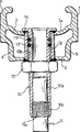
Fig. 1 is the cutaway view of the wheel rim of first embodiment according to the invention, and cutting plane comprises the axle center of this wheel rim and the position that charge valve is installed;
Fig. 2 explains and understands first example application according to second embodiment of the invention;
Fig. 3 and Fig. 4 explain and understand two other example application according to second embodiment of the invention.
The specific embodiment
In the drawings, corresponding components refers to identical reference number.
In Fig. 1, reference number 1 refers to the wheel rim of cycle wheel on the whole, this wheel rim comprises inside circumference wall 2, outer circumference wall 3, twice circumferential side wall 4,5, this sidewall couples together circle wall 2,3 and is extending radially outwardly to outside the circle wall 3, thereby has formed the holding flange 6,7 of fix tubeless tyres (not shown).In the installation position of the charge valve of giving inflation of tire, two circle wall 2,3 have two relative holes 8,9, and radially there is a common axis in these two holes the wheel rim axle center, and the port in these holes is being fixed centre pipe fitting 10 with welding or other bonding modes S.The front end face radial outward of middle pipe fitting 10 is also referred to by 10a.The shape of end face 10a is processed into concordant with the outside face 3a of the outer circumference wall 3 of wheel rim.In addition, a part of 10b of middle pipe fitting 10 stretches out outside inside circumference wall 2 towards the axle center (not shown) of wheel rim, and terminates in the end 10c of band negative thread 10d.Reference number 11 refers to the valve body (just schematically illustrated) of the cycle wheel that is generally used for inner tube of a tyre tire of standard form.The inner structure of valve body 11 is also not shown, because its structure is known fully.Valve body 11 has one section middle part threaded portion 11a, female thread portion 10d the inside of pipe fitting 10 in the middle of this part is screwed in.
Fig. 2 shows second embodiment, and in this embodiment, middle pipe fitting 10 and wheel rim 1 are connected with removably.In the example application of Fig. 2, the outside of the radial outward end 10e of middle pipe fitting 10 is processed with screw thread and is screwed on the inner threaded surface of lining 12, and two end bonds by welding or other bonding modes S or is welded on inside the port in hole 8,9.The end 10e of middle pipe fitting 10 also is provided with the O shape circle 13 in the circumferential groove that is in described end 10e, this O shape is enclosed 13 pressurizeds and is contacted with the inside face of lining 12, thereby guaranteed air-tightness, in order to avoid overflow the cavity of air between tire self (not shown) and wheel rim outer circumference wall 3.In addition, middle pipe fitting 10 is provided with the baffle ring 10f of ring-type to the 10g that shows up, and the radial inner end face of described corresponding surface 10g and lining 12 is fitted.
Compare with Fig. 1, the structure of the embodiment shown in Fig. 2 is complicated a little, but possesses the advantage of this wheel rim being changed easily apace the wheel rim that becomes to be used to have inner tube of a tyre tire.In fact in this case, only need following steps just much of that: pipe fitting 10 and it is removed in the middle of unscrewing, load onto the inner tube of a tyre of tire then in normal way, and coupled valve body is passed from the inside of lining.
Fig. 3 shows the modification of Fig. 2, and in this modification, middle pipe fitting 10 is connected in the lining 12 with another removably.Reality in this case, middle pipe fitting 10 has a head 14 that increases at its radial outer end, this head is supported by the outside face 3a of outer circumference wall 3.In addition, middle pipe fitting 10 extend part 10b outside the inside circumference wall 2 have can with nut 15 bonded assembly screw threads, thereby nut 15 plays a part that head 14 is tightened in bearing surface 3a middle pipe fitting 10 is fixed on the wheel rim.In the example application in Fig. 3, middle pipe fitting 10 also is provided with two O shapes circle 13, and this O shape circle 13 mediates respectively in the twice circumferential groove of pipe fitting 10.Scheme among Fig. 3 also clearly can be changed this wheel rim the tire that becomes to be applicable to the band inner tube of a tyre at an easy rate.
The difference of the example application among Fig. 4 and Fig. 3 mainly is to have removed lining 12.In this case, air-tightness guarantees by single O shape circle 16, and this O shape circle 16 is in 9 mouthfuls the top layer circumferential groove 17 along the hole of surperficial 3a.At wheel rim is under the situation about being made by composite material, wheel rim or the light alloy wheel rim strengthened of carbon fiber for example, and a kind of scheme in back is much better, and reason is to have saved welding or other bonding modes.Except O shape circle 16, also can use some other sealing means, as gluing.In addition, the shape of head 14 can be processed to coordinate with the profile of surperficial 3a.
Can clearly draw from the fwd explanation, simple relatively according to rim construction of the present invention, cost is also low, and has also guaranteed the height air-tightness of tyre cavity simultaneously.This wheel rim also possesses simple, the fast speed advantage of dismounting, and is last, among second embodiment of the example application indication among Fig. 2,3,4, this wheel rim can be changed the wheel rim that becomes to be applicable to tube-tyre easily apace in front.
Certainly, principle of the present invention is not existed under the situation of misunderstanding, with respect to only explanation and the diagram done of mode by way of example herein, under the prerequisite that does not break away from category of the present invention, the details place of structure and embodiment can do very large-scale variation.
Claims (20)
1. wheel rim that is applicable to the cycle wheel that tubeless tires is housed, described wheel rim comprises:
Radially inner side circle wall (2);
Radial outside circle wall (3);
The twice circumferential side wall (4,5) that outside circle wall (2,3) in described is coupled together, in described wheel rim, described sidewall (4,5) radially extends and extends outside the described outer circumference wall (3), thereby has formed the flange (6,7) of twice fix tubeless tyres; With
Be rigidly attached to the inflation valve body (11) on the described interior outside circle wall (2,3), be used for inflating to the cavity that the described outer circumference wall (3) by tire and wheel rim limits, described inflation valve body (11) is the valve body on a kind of cycle wheel that can be used for tube-tyre of standard form
Described wheel rim is characterised in that, described valve body (11) is to be connected in wheel rim described on the outside circle wall (2,3) by pipe fitting (10) in the middle of, wherein, described pipe fitting (10) is contained in two opposed facing respectively holes (8,9) that outside circle wall (2,3) upward forms in described, the part (10b) of described pipe fitting (10) radially and towards the axle center of wheel rim extends to outside the described inside circumference wall (2), and valve body (11) just is fixed on the described part (10b).
2. wheel rim according to claim 1 is characterized in that, the outside face of described valve body (11) has a threaded part (11a), and described threaded portion (11a) is screwed in the threaded portion (10d) of pipe fitting (10) inside face in the middle of described.
3. wheel rim according to claim 2 is characterized in that, described in the middle of the forming the end of pipe fitting (10) in the middle of described of pipe fitting (10) inside face with described valve body (11) bonded assembly threaded portion (10d).
4. according to any one described wheel rim in the claim 1 to 3, it is characterized in that, described in the middle of pipe fitting (10) be provided with bonding or be welded on radial outer end (10a) on the described outer circumference wall (3) of wheel rim.
5. wheel rim according to claim 4 is characterized in that, described in the middle of the described radial outer end (10a) of pipe fitting (10) be sealing adhesive or be welded on the port in the hole (9) on the described outer circumference wall (3) of wheel rim.
6. wheel rim according to claim 5 is characterized in that, described middle pipe fitting (10) also bonds or is welded on the inside circumference wall (2) of wheel rim.
7. wheel rim according to claim 4 is characterized in that, the front surface of the described radial outer end (10a) of described middle pipe fitting (10) keeps concordant fully with the outside face (3a) of the described outer circumference wall (3) of wheel rim.
8. according to any one described wheel rim in the claim 1 to 3, it is characterized in that described middle pipe fitting (10) is connected with removably with described wheel rim.
9. wheel rim according to claim 8, it is characterized in that, pipe fitting (10) is provided with removably and is installed in radial outer end portion (10e) in the lining (12) in the middle of described, and the two ends of described lining (12) are separately fixed in the relative hole (8,9) of outside circle wall (2,3) in wheel rim described.
10. wheel rim according to claim 9 is characterized in that, the radial outer end portion of described lining (12) keeps concordant fully with the outside face (3a) of the described outer circumference wall (3) of wheel rim.
11. wheel rim according to claim 9 is characterized in that, described lining (12) bonds or is welded on the port in described relative hole (8,9).
12. wheel rim according to claim 9 is characterized in that, is provided with sealing arrangement (13) between described middle pipe fitting (10) and described lining (12).
13. wheel rim according to claim 12 is characterized in that, described sealing arrangement (13) comprises one or more O shape circles (13).
14. wheel rim according to claim 13 is characterized in that, described O shape circle (13) be contained in described in the middle of in the circumferential groove of pipe fitting (10), and be depressed into the inside face of described lining (12) and contact.
15., it is characterized in that described middle pipe fitting (10) is threaded in the described lining (12) according to any one described wheel rim in the claim 9 to 14.
16. wheel rim according to claim 15 is characterized in that, described in the middle of pipe fitting (10) be provided with the ring-type of fitting to show up (10g) with the radial inner end face of described lining (12).
17. according to any one described wheel rim in the claim 9 to 14, it is characterized in that, described middle pipe fitting (10) is provided with the broadening head (14) by outside face (3a) support of the described outer circumference wall (3) of wheel rim, and stretch out threaded portion (10b) outside the described inside circumference wall (2) towards the axle center of wheel rim, nut (15) is screwed on the described threaded portion (10b), thereby described head (14) is tightened on its bearing surface.
18. wheel rim according to claim 8, it is characterized in that, pipe fitting (10) passes described relative hole (8,9) direct connection on wheel rim in the middle of described, and be provided with the broadening head (14) that the outside face (3a) by the described outer circumference wall (3) of wheel rim supports, and stretch out threaded portion (10b) outside the described inside circumference wall (2) towards the axle center of wheel rim, nut (15) is screwed on the described threaded portion (10b), thereby described head (14) is tightened on its bearing surface.
19. wheel rim according to claim 18 is characterized in that, is provided with sealing arrangement (16) between described head (14) and its bearing surface.
20. wheel rim according to claim 19 is characterized in that, described sealing arrangement (16) comprises in the preceding annular recess (17) on the outside face (3a) of the described outer circumference wall (3) that is contained in wheel rim and along the O shape circle on the limit of each hole (9).
Applications Claiming Priority (2)
| Application Number | Priority Date | Filing Date | Title |
|---|---|---|---|
| IT2000TO000775A IT1320582B1 (en) | 2000-08-03 | 2000-08-03 | CIRCLE FOR A BICYCLE WHEEL WITH TIRE WITHOUT AIR CHAMBER. |
| ITTO2000A000775 | 2000-08-03 |
Publications (2)
| Publication Number | Publication Date |
|---|---|
| CN1337325A CN1337325A (en) | 2002-02-27 |
| CN1221413C true CN1221413C (en) | 2005-10-05 |
Family
ID=11457983
Family Applications (1)
| Application Number | Title | Priority Date | Filing Date |
|---|---|---|---|
| CN01125044.5A Expired - Fee Related CN1221413C (en) | 2000-08-03 | 2001-08-03 | Wheel rim suitable for wheel of bicycle fitted with tyre without innertube |
Country Status (10)
| Country | Link |
|---|---|
| US (2) | US6588474B2 (en) |
| JP (1) | JP2002087004A (en) |
| CN (1) | CN1221413C (en) |
| BE (1) | BE1015382A3 (en) |
| CZ (1) | CZ298007B6 (en) |
| FR (1) | FR2812587B1 (en) |
| IT (1) | IT1320582B1 (en) |
| NL (1) | NL1018692C2 (en) |
| PT (1) | PT102654B (en) |
| TW (1) | TW495449B (en) |
Families Citing this family (33)
| Publication number | Priority date | Publication date | Assignee | Title |
|---|---|---|---|---|
| TW514031U (en) * | 2002-04-30 | 2002-12-11 | Jen-Ping Tian | Improved fabricating structure for spokes of wheel rim on a bicycle |
| US20040066085A1 (en) * | 2002-10-05 | 2004-04-08 | Jason Schiers | One-piece composite rim |
| TW549249U (en) * | 2002-10-16 | 2003-08-21 | Alex Global Technology Inc | Wheel rim for bicycle with protruded corner strengthening structure |
| ATE390297T1 (en) | 2002-11-08 | 2008-04-15 | Campagnolo Srl | METHOD FOR PRODUCING A SPOKE WHEEL FOR BICYCLES |
| US6736462B1 (en) * | 2002-12-16 | 2004-05-18 | Shimano, Inc. | Bicycle rim |
| US20040189548A1 (en) * | 2003-03-26 | 2004-09-30 | Ngk Insulators, Ltd. | Circuit element, signal processing circuit, control device, display device, method of driving display device, method of driving circuit element, and method of driving control device |
| US7192098B2 (en) * | 2003-05-07 | 2007-03-20 | Shimano Inc. | Bicycle rim |
| PT1491362E (en) * | 2003-06-26 | 2008-07-18 | Campagnolo Srl | Lightened rim for a bicycle wheel and method for manufacturing such a rim |
| US20050023883A1 (en) * | 2003-08-01 | 2005-02-03 | Shimano Inc. | Bicycle rim |
| DE60322051D1 (en) * | 2003-08-11 | 2008-08-21 | Campagnolo Srl | Bicycle rim made of composite material and method for its production |
| US20050194834A1 (en) * | 2004-03-03 | 2005-09-08 | Chun-Hsung Chen | Bicycle spoke fixture assembly |
| US20050210675A1 (en) * | 2004-03-26 | 2005-09-29 | Price Chad N | Sealed tubeless tire bicycle wheel |
| DE202005004399U1 (en) * | 2005-03-16 | 2005-06-09 | Dymag Racing Uk Ltd. | Wheel for vehicles, in particular, for automobiles and motorcycles comprises at least one connector element which joins the spoke assembly or the wheel disk to the wheel rim, and is fully screened from the view |
| ITPD20050271A1 (en) * | 2005-09-21 | 2007-03-22 | Alpina Raggi Spa | METHOD FOR MANUFACTURING A SPOKE WHEEL AND WHEEL OBTAINED WITH THIS METHOD |
| ITMI20072231A1 (en) * | 2007-11-26 | 2009-05-27 | Campagnolo Srl | RIM FOR BICYCLE WHEEL AND BICYCLE WHEEL INCLUDING SUCH RIM |
| ITMI20072232A1 (en) * | 2007-11-26 | 2009-05-27 | Campagnolo Srl | RIM FOR BICYCLE WHEEL AND BICYCLE WHEEL INCLUDING SUCH RIM |
| EP2100751B1 (en) * | 2008-03-14 | 2011-05-18 | Campagnolo S.r.l. | Rim made from composite material for a tubeless bicycle wheel and tubeless bicycle wheel comprising such a rim |
| CN102275473A (en) * | 2011-05-30 | 2011-12-14 | 开平市中铝实业有限公司 | Inflating valve structure for automobile hub |
| US9651138B2 (en) | 2011-09-30 | 2017-05-16 | Mtd Products Inc. | Speed control assembly for a self-propelled walk-behind lawn mower |
| US20130186536A1 (en) * | 2012-01-19 | 2013-07-25 | Chin Chuan Lee | Valve device for tubeless tire |
| ITVI20120092A1 (en) * | 2012-04-20 | 2013-10-21 | Alberto Deanesi | VALVE GROUP PERFECTED FOR THE WHEEL INFLATION |
| EP2666651A1 (en) * | 2012-05-22 | 2013-11-27 | Bao Ley Co., Ltd. | Valve device for a tubeless tire |
| US20140132057A1 (en) * | 2012-11-09 | 2014-05-15 | Chin Chuan Lee | Valve device for tubeless tire |
| ITMI20130201A1 (en) * | 2013-02-13 | 2014-08-14 | Campagnolo Srl | CIRCLE OF BICYCLE WHEEL AND RELATED BICYCLE WHEEL |
| CN103303081A (en) * | 2013-07-08 | 2013-09-18 | 天津富士达自行车有限公司 | Bicycle inner tube |
| US20150165845A1 (en) * | 2013-12-17 | 2015-06-18 | Aeromind, LLC | Valve Stem for a Pneumatic Wheel |
| ITUA20161779A1 (en) * | 2016-03-17 | 2017-09-17 | Campagnolo Srl | Bicycle wheel and related manufacturing process |
| ITUA20162810A1 (en) * | 2016-04-22 | 2017-10-22 | Barbieri S N C Di Barbieri Nadia E Kalman | ENGAGEMENT AND VALVE UNIT FOR TUBELESS TIRES, AND RELATED ASSEMBLY PROCEDURE |
| ITUA20164723A1 (en) * | 2016-06-28 | 2017-12-28 | Alpina Raggi Spa | Nipple for tubeless spoke wheels |
| IT201600069496A1 (en) * | 2016-07-05 | 2018-01-05 | Barbieri S N C Di Barbieri Nadia E Kalman | ENGAGEMENT AND VALVE GROUP FOR AIRBUSES |
| IT201600082758A1 (en) * | 2016-08-05 | 2018-02-05 | Barbieri S N C Di Barbieri Nadia E Kalman | ENGAGEMENT AND VALVE GROUP FOR AIRBUSES |
| US10807424B2 (en) * | 2018-01-05 | 2020-10-20 | Specialized Bicycle Components, Inc. | Tubeless valve assembly |
| DE102021209064A1 (en) * | 2021-08-18 | 2023-02-23 | Robert Bosch Gesellschaft mit beschränkter Haftung | Valve adapter and system for fixing a valve. |
Family Cites Families (17)
| Publication number | Priority date | Publication date | Assignee | Title |
|---|---|---|---|---|
| US2835305A (en) * | 1955-01-05 | 1958-05-20 | Dill Mfg Co | Tubeless tire valves for trucks and the like |
| US3635275A (en) * | 1969-12-15 | 1972-01-18 | Melvin Lee Davis | Tractor tire valve assembly |
| DE3238928A1 (en) * | 1982-10-21 | 1984-04-26 | Continental Gummi-Werke Ag, 3000 Hannover | VALVE FOR TUBELESS TWO WHEEL BIKES |
| US5040612A (en) * | 1989-10-30 | 1991-08-20 | Allen William H | Apparatus for fire fighting with liquid ballast in vehicle tire of tube and tubeless variety |
| JPH0365990U (en) * | 1989-10-31 | 1991-06-26 | ||
| US5211782A (en) * | 1991-09-06 | 1993-05-18 | Donald Thelen | Valve assembly for tubeless tire |
| US5564056A (en) * | 1994-03-01 | 1996-10-08 | Intel Corporation | Method and apparatus for zero extension and bit shifting to preserve register parameters in a microprocessor utilizing register renaming |
| FR2744953B1 (en) * | 1996-02-19 | 1998-04-03 | Hutchinson | SPOKE WHEEL RIM FOR BEING EQUIPPED WITH A TIRE WITHOUT CHAMBER, AND SPOKE WHEEL THUS EQUIPPED |
| US5746850A (en) * | 1996-04-26 | 1998-05-05 | Luscher; Marcus P. | Double inner tube and valve system |
| FR2750913B1 (en) * | 1996-07-12 | 1998-10-09 | Mavic Sa | METHOD OF DRILLING A SPOKED RIM, RIM DRILLED ACCORDING TO THE METHOD, INSERT SUITABLE FOR EQUIPMENT ON THE RIM, AND WHEEL IN PARTICULAR FOR A CYCLE |
| US6009895A (en) * | 1996-12-23 | 2000-01-04 | Mirada Research & Manufacturing, Inc. | Free rotating inlet check valve for inflatable devices |
| JPH10250309A (en) | 1997-03-17 | 1998-09-22 | R Thomasberg Paul | Tubeless tire and rim for bicycle |
| FR2766424B1 (en) * | 1997-07-25 | 1999-10-01 | Mavic Sa | VALVE AND RIM FOR BICYCLE WHEEL PROVIDED FOR TUBELESS MOUNTING |
| FR2766419B1 (en) * | 1997-07-25 | 1999-10-01 | Mavic Sa | BICYCLE RIM PROVIDED FOR TUBELESS MOUNTING AND BICYCLE WHEEL |
| FR2787064B1 (en) * | 1998-12-14 | 2001-03-02 | Mavic Sa | INFLATION VALVE FOR A BICYCLE WHEEL TYPE WITHOUT TUBE |
| US6145937A (en) * | 1999-07-13 | 2000-11-14 | Alex Machine Industrial Co., Ltd. | Bicycle wheel rim |
| JP3065990U (en) * | 1999-07-23 | 2000-02-08 | 亞獵士工業股▲ふん▼有限公司 | Bicycle wheel rim and wheels with this wheel rim |
-
2000
- 2000-08-03 IT IT2000TO000775A patent/IT1320582B1/en active
-
2001
- 2001-07-13 TW TW090117195A patent/TW495449B/en active
- 2001-07-26 JP JP2001225899A patent/JP2002087004A/en active Pending
- 2001-07-31 BE BE2001/0519A patent/BE1015382A3/en not_active IP Right Cessation
- 2001-08-01 FR FR0110351A patent/FR2812587B1/en not_active Expired - Fee Related
- 2001-08-02 PT PT102654A patent/PT102654B/en not_active IP Right Cessation
- 2001-08-02 US US09/919,903 patent/US6588474B2/en not_active Expired - Fee Related
- 2001-08-02 NL NL1018692A patent/NL1018692C2/en not_active IP Right Cessation
- 2001-08-03 CN CN01125044.5A patent/CN1221413C/en not_active Expired - Fee Related
- 2001-11-05 CZ CZ20013971A patent/CZ298007B6/en not_active IP Right Cessation
-
2003
- 2003-07-07 US US10/614,226 patent/US6820668B2/en not_active Expired - Fee Related
Also Published As
| Publication number | Publication date |
|---|---|
| PT102654B (en) | 2003-07-31 |
| ITTO20000775A0 (en) | 2000-08-03 |
| PT102654A (en) | 2002-02-28 |
| FR2812587A1 (en) | 2002-02-08 |
| US20020014293A1 (en) | 2002-02-07 |
| JP2002087004A (en) | 2002-03-26 |
| CZ298007B6 (en) | 2007-05-23 |
| FR2812587B1 (en) | 2005-07-08 |
| CZ20013971A3 (en) | 2002-08-14 |
| IT1320582B1 (en) | 2003-12-10 |
| CN1337325A (en) | 2002-02-27 |
| TW495449B (en) | 2002-07-21 |
| NL1018692C2 (en) | 2002-02-05 |
| US20040021368A1 (en) | 2004-02-05 |
| ITTO20000775A1 (en) | 2002-02-03 |
| US6588474B2 (en) | 2003-07-08 |
| BE1015382A3 (en) | 2005-03-01 |
| US6820668B2 (en) | 2004-11-23 |
Similar Documents
| Publication | Publication Date | Title |
|---|---|---|
| CN1221413C (en) | Wheel rim suitable for wheel of bicycle fitted with tyre without innertube | |
| US7431404B2 (en) | Bicycle having annular sealing member | |
| US6145936A (en) | Spoke wheel for a tubeless tire | |
| US6474746B2 (en) | Bicycle wheel rim | |
| CN103057350B (en) | Bicycle wheel rim structure | |
| US6582029B2 (en) | Bicycle rim | |
| CN104053557A (en) | Two-part wheel | |
| JP2002166701A (en) | Spoke wheel and corresponding nipple for attaching the spoke | |
| TWM615623U (en) | Bicycle spoke fastening structure | |
| JPS62227801A (en) | Wheel for motorcycle | |
| CN110065346B (en) | Wheel device suitable for new energy automobile | |
| TWI596021B (en) | Spoke wheel, particularly for a tubeless-type tyre, intended to be mounted on a vehicle, particularly on a motor vehicle or a motorcycle | |
| US6119746A (en) | Valve and rim for bicycle wheel provided for a tubeless assembly | |
| CN207224981U (en) | Cycle wheel, non-inflatable tyre and rim | |
| CN209795049U (en) | wheel for loading hub motor | |
| US20170267021A1 (en) | Bicycle wheel and relative manufacturing process | |
| JPS6154302A (en) | Spoke wheel for tubeless tire | |
| US20150217597A1 (en) | Plug for a tubeless bicycle wheel | |
| RU227861U1 (en) | DISASSEMBLE WHEEL RIM FOR TUBELESS TYRES | |
| CN219154167U (en) | Inflating valve structure of wheel rim | |
| US20130300186A1 (en) | Vehicle wheel spoke connection | |
| CN221292791U (en) | Automobile hub casting | |
| CN214138111U (en) | Wheel and have its vehicle | |
| CN209063820U (en) | Fetus in fetu trouble-proof tire | |
| CN212604273U (en) | Novel tubeless wheel rim |
Legal Events
| Date | Code | Title | Description |
|---|---|---|---|
| C06 | Publication | ||
| PB01 | Publication | ||
| C10 | Entry into substantive examination | ||
| SE01 | Entry into force of request for substantive examination | ||
| C14 | Grant of patent or utility model | ||
| GR01 | Patent grant | ||
| C17 | Cessation of patent right | ||
| CF01 | Termination of patent right due to non-payment of annual fee |
Granted publication date: 20051005 Termination date: 20090903 |