Background technology
Recording type optical disc can keep bulk information and have the feature of replaceable (getting final product justice changes) media.In the information process of playback of recorded on CD, beam of laser is aimed at its information record side, and the light that is recorded mark modulation is reflected and is used for detecting.In the cd-rom recording of information process, proportion is let slip in the journey used laser power and is wanted big laser beam effect information record side, and thermic forms record mark.
The recording type optical disc media roughly is divided into following three classes: (1) magneto-optical, (2) inversion of phases and (3) pit type.To regenerative recording, magneto-optical CD widespread use, and to the Write-only one time type record is that the organic pigment pit type CD of representative is very universal to write down tight dish (CD-R).
For improving the storage density of recording type optical disc, palpus is controlling recording power accurately, and this is owing to should be able to form less record mark with more and more higher density with more and more higher precision.Yet, constant although the output level of light source keeps in the optical disc apparatus of reality, owing to for example adverse effect of dynamic changes such as environment temperature, optical maser wavelength, luminous point distortion, be difficult to provide a required Temperature Distribution in optical disc information record side.
Therefore, as what separated, record the information in record with so-called " examination is write " technology and closely coil on (CD-R) in the uncensored patent disclosure 195713/1994 of Japan.Utilize this technology, can adopt examination to write before record user's data, the optimizing level with detection record power be write in the examination that utilization is finished in predetermined test site.
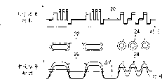
Darker this discussion, shown in Fig. 2 a, the expression test writing method alternately writes down meticulous and rough pattern.More precisely, laser beam is utilized and is produced rough 22 and meticulous 24 pit in the recording medium of wave recording 20, and playback time obtains replay signal 26 and 28 respectively from rough 22 and meticulous 24 pit.Utilize replay signal, detect average electrical adjustment between the meticulous and rough pattern, promptly asymmetry value Δ V is (Fig. 2 a), and the recording power level Po when detecting asymmetry value and being about zero (example in the middle of Fig. 2 b), as optimum recording status.Less than Po (Fig. 2 b, last example), owing to the shape of record mark less than regulation, Δ V is a negative value as recording power level P.On the contrary, as recording power level P greater than Po (Fig. 2 b, following example), because record mark is greater than the shape of regulation, Δ V be on the occasion of, therefore the power P o when changing recording power at proper range and detecting asymmetry value Δ V=o utilizes the detection of asymmetry value Δ V can measure optimum recording power level Po.Utilize this method,,, also can obtain linear response although its length changes as long as the width of record mark is constant.
Now further describe background and application above-mentioned " asymmetry value detection " problem that test writing method took place when record on phase change disc is discussed.The information of difference playback of recorded on phase change disc of reflectivity between crystalline state and the amorphous state owing to utilize the medium, the playback circuitry of available and the used same type of CD-ROM, promptly phase transition optical disk has and the compatible advantage of ROM type CD.
For the background of phase transition optical disk,, form record mark as amorphous state by utilizing laser on its recording layer, to melt luminous point and extinguishing luminous point subsequently.For wiping record mark, utilize temperature to make its amorphous crystallization greater than the crystallization level and less than the LASER HEATING radiation light point of melting point.Postpone the fall time as fusing back in the information record, luminous point is crystallization again, and this phenomenon is called " crystallization again ".Therefore the shape of record mark depends on the Temperature Distribution of luminous point cooling situation and gained.These are the singularity of phase transition optical disk pen recorder, and are different as other device of this class CD of magneto-optic disk with record.
Check in the example at phase transition optical disk, utilize the GeSbTe phase-change material to serve as the performance of typical " asymmetry detection " test writing method of recording layer test.The example dish is made of the plastic-substrates of diameter 120mm thickness 0.6mm, and has ZnS-SiO2 main optical interfering layer, GeSbTe recording layer, ZnS-SiO2 second optical interference layer, the lamination of Al-Ti reflection horizon and UV protective seam.In substrate, form the track groove that the about 0.7um of spacing is used for the platform group record.Use three the recording level Pw that have shown in Figure 3, the wave recording of Pe and Pb, and adopt channel clock signal Tw (T is the channel bit length that presets).For forming record mark nTw, use ' n-1 ' Tw/2 broad pulse.To the data modulation, can adopt " 8-16 " modulator approach of the about 0.2 μ m of 1Tw.The shortest mark lengths is 3Tw, and longest mark length is 14Tw.Send the laser beam of wavelength 680nm from semiconductor laser.The luminous point that is formed for writing down by object lens focusing through numeric aperture values 0.6.Measure and use the 6m/s linear velocity.The central value that rewrites the power margin Po of random signal on the example dish is 10.5mW under the Pw situation, is 3.8mW under the Pe situation.Change and to be used to the recording power that tries to write, keeping Pw/Pe ratio simultaneously is 10.5mW/3.8mW.The Pb level keeps being stabilized in 0.5mW.Repeat 3Tw mark space record and be used for fine pattern, be used for rough pattern and make repetition 8Tw mark space record by generation.
Fig. 4 shows the curved line relation between the recording power and asymmetry value Δ V in the above-mentioned test process, and the problem that is caused by recrystallization.On the ordinate of this chart, asymmetry value Δ V amplifies with rough pattern signal and carries out normalized.In recording power 9-14mW scope.Asymmetry value Δ V has increases performance gradually, and positive side increases to 15% and minus side changes only approximately 3%, and in the scope of recording power less than Po, the slope of asymmetry value Δ V has mild relatively trend.Near record start point, the code paradox takes place.
These performances in the low recording power scope are caused by the problem of the above-mentioned recrystallization in the record, have more ground, the rough and fine pattern of contrast, and the laser emission time of fine pattern is less than rough pattern.Therefore, the hot reserving degree of fine pattern is low, and heating and cooling are faster, causes the recrystallization degree low.Because the difference of recrystallization is bigger near the record threshold value between rough and the fine pattern, the width of the record mark of fine pattern is wideer than rough pattern.Asymmetry value changes different at positive side and minus side, corresponding a certain level recording power can not clearly be measured its asymmetry value, and meaning needs the Combined Processing operation, is used for using " asymmetry detection " test writing method to measure optical power level Po.
Rewriting relevant performance and problem in serviceable life with phase transition optical disk is described below.When repeat to rewrite on phase transition optical disk, dish progressively damages.Two damage phenomenons the most tangible are; (1) change of the fluidisation of recording layer and (2) reflectivity.It is believed that, the fluidisation of recording layer is owing to the thermal stress that acts in the recording layer molten state when writing down causes, the change of reflectivity is relevant with the fluidisation phenomenon of recording layer, think that it is owing to the segregation as the recording layer component, this type of reason that the thermal stress such as infiltration of interfering layer material cause causes, the change of reflectivity is relevant with the fluidisation phenomenon of recording layer, thinks that it is that this type of reason that the thermal stress such as infiltration of interfering layer material cause causes owing to the segregation as the recording layer component.
Fig. 5 a and Fig. 5 b represent to test the example that detects used phase transition optical disk degrade performance.With reference to figure 5a, the length of expression record mark and the relation between the fluidisation degree.Adopt recording power Po to rewrite 80,000 times continuously in the detection.Each pattern of Fig. 5 a represents to comprise on an equal basis the repeat patterns of mark and space code.50 byte interval just write down each block that 200 bytes are formed.
For fluidisation, in the beginning of each block with finish to measure the start signal amplitude and reduce to zone length less than 1/2 o'clock.Among Fig. 5 a, the corresponding beginning of the length of each fluidisation area block is represented.Can find out that from this figure the short more fluidisation area length of mark lengths is but long more.For example, under 3Tw mark situation, its fluidisation area length is also longer than the twice of 11Tw mark.
Represent that with reference to figure 5b the reflected light par of 3Tw~8Tw pattern through rewriteeing carries out the normalized curve with 100% initial value level.When increasing rewrite operation quantity, catoptrical par level reduces.Relatively 3Tw and 8Tw pattern are rate of curve that the reflected light quantity of expression 3Tw pattern reduces and 8Tw pattern and unbecoming.This deterioration speed and fluidisation that shows recording layer depends on mark lengths.Because the difference of reflected light par level is represented asymmetric quantity, although the curve display of Fig. 5 b use the power of same level, asymmetric quantity changes with rewrite operation quantity.That is to say, different between the zone of Examination region that examination is write and physical record user data as rewrite operation quantity, can not measure the suitable recording level of laser power.
As mentioned above, the above-mentioned test writing method that discovery is dependent on " asymmetry detection " is not suitable for (promptly, be unfavorable for) mensuration of the optimal recording power level of phase transition optical disk, this is owing to following reason: (1) recrystallization and roughly with meticulous mark (pit) between heating/cool time different, (2) fluidisation, (3) correlativity of the improper linearity of impact point detection and indeterminate detection performance and damage of (4) recording layer and record mark length.
The purpose of this invention is to provide optimum recording power level that be fit to measure phase transition optical disk and overcome a kind of test writing method of following the above-mentioned shortcoming that " asymmetry detection " test writing method causes.Another purpose of the present invention provides a kind of optical disc apparatus that uses described method.
Embodiment
Finish the present invention and on the one hand, provide to solve/avoid the device of the problems referred to above, this device of following discussion by it.
(1) writes down in rough and the fine pattern,, different recording layers takes place worsen according to the length of record mark.For preventing/avoid that this phenomenon influences test writing method detection laser of the present invention and writes power, single labelled repeating signal (that is 11T high low signal/mark) is used for pattern recording.More precisely, analyze from Fig. 5 a empirical curve, and the understanding selection 11T high low signal/mark that presents superperformance according to fluidisation phenomenon 11T high low signal/mark.
(2) be used to test equivalent instable recording power level, the phase differential between the edge of data detection signal and the clock signal (drawing) when change from the phaselocked loop of replay signal.Through this test, measure that corresponding instability is lower than pre-set factory (that is, 1.25) thus measure the best titime situation.
With reference to figure 6, the graph of a relation between the instability of expression recording power and data and clock edge.More precisely, test the instability level (Fig. 6, harmonic curve) of the 11Tw marker spacing repeating signal of very first time record by mensuration, and the instability level (Fig. 6, high curve) that rewrites the back random signal for the tenth time, draw this figure.Usually, with the ECC code correction on the CD time, the permission boundary is that the bit error rate of replay data is 1/1000~1/10000.Therefore, about 15% instability level is the upper limit that prevents error, and this 15% presets limit (although available other presets limit, as, 10%, 20% satisfies any standard, or the power level measuring accuracy that acquires a certain degree) as what the present invention analyzed.As shown in Figure 6, the instability that rewrites the back random signal is less than centered level (that is target record value of 10.8mW) examination being write, of 15% recording power compass.Especially particularly, in case adopt the power level that increases to try to write, find that Fig. 6 curve and curve ranges have the instability less than 15%, can select recording power is the interior any power of 15% curve ranges.Best, select suitable centralized positioning power (as, the power of the center of 15% curve ranges), perhaps, select to cause the power (as, 10mW among Fig. 6) of minimum instability level.Yet, the existing in front narration of You Yi power selection method more.
For guaranteeing that the present invention tries to write the purpose that is applied to various CDs, utilize five recording layer component example dishes (5 differences in Fig. 7 a, 7b curve represented) different to test with structure.Test result is represented the detection that tries to write.Among Fig. 7 a and the 7b, horizontal seat is represented ratio ' η ' between the threshold power of the threshold power of section start DC light beam record and arteries and veins record.Big as this value, the recording layer that exposes fusing to the open air through the DC light beam is easy to by recrystallization crystallization once more, that is, Fig. 7 a horizontal ordinate is represented the recrystallization possibility degree on each example dish.15% instability level curve slope ' m ' in Fig. 7 a ordinate representative graph 6.Shown in Fig. 7 a, when writing down intermediate value ' m ', random signal changes with value ' η ', and value ' m ' is big relatively and constant in 11Tw repeating signal record.
Measure among the record threshold power Pth, accuracy of detection uprises with value ' m ' increase, preferably reduces the change between the variety classes media.11Tw repeat patterns signal record is more suitable than random pattern signal record, and selects to wait for pattern as the preferred examination of test writing method of the present invention/device.Difference between Fig. 7 a11T and the random pattern record is that the instability of 11T single pattern repeating signal is mainly caused by the fluidisation of data edges, otherwise the instability of random signal also comprises the drift component (it is good unlike the present invention therefore random pattern to be write down) that depends on mark lengths except that the fluidized composition at data edge.
With reference to figure 7b, expression value ' η ' and best power are with the graph of a relation between the record threshold power ratio ' α '.Especially particularly, as described in Fig. 7 b, running into the 15% occurrence record threshold power Pth of instability level place (after initial code is put upside down the peak), and best power Po for example is, in 15% instability curve ranges center power level.Shown in Fig. 7 b experiment and result curve, 5 have the threshold power that tests out on the example dish of different performance and the ratio between the best power ' α ' is about 1.25 constant.According to Fig. 7 b test result, as a method for optimizing, discovery can be write down power threshold value Pth by obtaining, and (as described in) with reference to figure 1b, and multiply by than numerical constant ' α ' (that is, above-mentioned 1.25 values), can measure the optimum power level in the single pattern record.
Comprehensive discussion, owing to can progressively scan through low-level of power and clearly measure 15% curve ranges and relative recording threshold power, and multiplication ratio ' α ' can adopt above-mentioned 1.25 values, but or measuring, or provide by the dish manufacturer, can finish the examination write operation of the recording power level that be fit to detect the load phase transition optical disk.Described the present invention relevant, believed that the present invention also is applicable to magneto-optic disk and pit type Write-once CD with phase transition optical disk.The inventive method/device is equally applicable to the dish of other type.
Several embodiment now are discussed.
<embodiment〉test writing method:
Fig. 1 a and 1b represent the phase difference detection device and the method figure of the preferred embodiment of the present invention, with and the experimental result write of figure pilot scale, i.e. expression " phase differential " test writing method and device.Especially particularly, with reference to figure 1a, the edge pulse of data-signal and clock signal (proposing from replay signal through unshowned phase-locked loop circuit) inputs to phase comparator, and phase comparator produces the length pulse signal of the phase differential between the edge with corresponding clock and data-signal.So the pulse signal that produces is input into integrator, and pulse width is changed into phase error voltage than threshold level height, and the data edges pulse is sent to error counter as error pulse, carries out stored counts.Simultaneously, the edge counter calculates all data edges pulses, arrives setting in this calculating operation process, and error counter stops.The error count value input CPUC that obtains in error counter then is with processing execution.In the described here chart, the edge sum that the corresponding edge counter calculates, instable value is compared with clock, as the representative phase differential ratio input CPU bigger than threshold value.The advantage of this method is at the inhomogeneous record susceptibility of section of resetting, when the phase error voltage that the fluctuation of servocontrol error etc. causes changes, these variations can be accumulated into umber of pulse, in order to the high stability of test steadily to be provided.Simultaneously, in the method, the scale of necessary circuitry can advantageously be made littler than the sort of device that phase error voltage directly will be imported by AD converter or other device.By quantitative celebrating victory mutually between clock and data edges as mentioned above, in optical disc apparatus, can measure the physical quantity that is equal to the instability value that obtains by measurement mechanism as the instability analysis device.
With reference to figure 1b, expression utilizes phase difference detection method of the present invention to finish the test findings figure that examination is write.In this test, adopt the used example dish of Fig. 6 experimental measurement again as recording medium.The phase error voltage of 1.8V when thereby the gain of determining integrator obtains window width Tw generation ± 50% skew.This value is equal to 0.01V/deg phase differential susceptibility.The threshold value of level comparator is 0.8V (window width ± 22%), and the predetermined value of edge counter is 1560.For recording figure forming, under the firm power situation of Pw:Pe=11Mw:45mW, adopt dimple size 11TTw repeating signal record.Shown in Fig. 1 b, the error count of corresponding record power changes consistent with the described instability characteristic of Fig. 6.Power threshold value Pth is 8.8mW, and multiply by the record situation value Po that ' α ' constant of 1.25 obtains 11mW.The 10.8mW actual measured value of comparison diagram 6, the error of said method are 2% or littler.Correspondingly, receivable error like this, thus can find out and threshold power that utilization is measured multiply by the α constant to measure the method for optimizing of best power Po be reliably and have superiority (that is, easily implementing) method.
With reference to figure 8, the circuit structure of the phase difference detector 800 that the expression actual measurement is used in the figure, has steering logic 802, phase comparator 804 (special use or logic) integrator 806 and error pulse generator 808.Further, SCLK represents the pll clock signal, RDGT represents the playback door of the data field on the corresponding section, PCA represents the data edges pulse signal, PCB represents the pulse signal of comparing with data edges from pll clock signal extraction, ERROR PULSE represents the error pulse signal, RESET represents the reset signal of integrator, S/H represents to take a sample and keeps phase place to miss the control signal of the voltage of celebrating victory, UP represent to compare with the pll clock pulse signal of the leading length of phase place with response data edge, DOWN are represented the compare pulse signal of length of phase lag with response data edge of pll clock.
With reference to the following description circuit operation of sequential chart shown in Figure 9.Utilize pll clock signal and binary data signal (DLDATA), produce pulse signal PCA and be used for bit comparison mutually with PCB.To producing PCA and PCB pulse, utilize gate array piece (Fig. 8 is not shown) with simple logic circuit.Utilize PCA and PCB pulse, produce two human connections towards signal UP and DOWN through d type flip flop and NAND gate circuit.By logic one " or " UP and DOWN pulse signal, promptly EXCLUSIVE-or PCA and PCB signal can obtain the phase differential pulse signal.In the integrator, so the phase differential pulse signal that obtains carries out the integration in 1.5Tw cycle.Integration is finished, and integrator resets.From the 0.5Tw of integration section start time point, take a sample and keep and transport to level comparator, thereby an error pulse signal is provided.In the preferred embodiment of the present invention, additionally need two counters that are used for the counting edge of error pulse and data edges, because these counter structures are simple, and easily finish through this area existing standard counter, so do not lay down a definition at this.
Described phase difference detection method, wherein had very big phase voltage and measure phase difference value, phase voltage can obtain through the integration of above-mentioned phase differential pulse signal.In this case, because integration may fluctuate in time, preferably provide additional low-pass filter or other like before by detections such as AD converter, to be suppressed at temporal fluctuation.
Below, the margin of error counting is described, the threshold value of electric comparer and the relation between the instability.With reference to Figure 10, the graph of a relation between the threshold value of expression margin of error counting and level comparator.Because integrator is set in previous experiments provides 0.01deg susceptibility, the threshold voltage value V1 of the corresponding 1.8V of the phase differential of ± Tw/2.Under the situation of 25% instability (being equal to maximal value) and 8% instability (being equal to minimum value), test.Because the representative of margin of error counting has the data edges count value of the phase differential bigger than threshold voltage, the margin of error counting raises with threshold voltage and reduces.When threshold voltage V1 is 0.8, the difference maximum of the margin of error counting between 25% instability and 8% instability.In this case, the variation maximum of corresponding instable variation error edge counting, thus can be used in the susceptibility maximum that the examination of detection threshold level is write.
With reference to Figure 11, the expression instability distributes.The schematic diagram of the relation between margin of error counting and the threshold voltage.As scheme pointedly, the bigger phase differential of phase threshold voltage (greater than threshold value) than the instability distribution takes place in the corresponding shadow region of the margin of error that count in the shadow region in.
With reference to Figure 12, expression instability and margin of error count measurement be figure as a result.Pointed as this figure, the margin of error counting is linear increasing with instable increase.Therefore this very clear number by the detection margin of error can be tested the instable value that is equal to, thereby has confirmed method of operating validity of the present invention.Ironically, when instability voltage is zero, not vanishing of error count, this is owing to depend on the compensation and the response speed of phase difference detecting circuit.Under the situation of the little degree of phase differential, thereby the interlock circuit device becomes invalid do not produce UP and DOWN pulse.This performance is dependent on used the changing from shape IC circuit structure of test.Yet 15% instability value for detecting confirms 7%~25% sensing range in experiment.Therefore, in fact try not write problem can take place.When finishing the present invention, need to consider sensing range and linearity with the LSI circuit arrangement.Simultaneously, put into practice when of the present invention, must consider threshold value and as the margin of error counting that detects target, detection sensitivity will can step-down like this.Relation between power shown in Fig. 1 b and the error count can obtain by above-mentioned layout.In the method for the invention, because error count with the variation of recording power big change takes place near the record threshold level, although because the change threshold voltage V1 of temperature or supply voltage effectively fluctuates, the error that recording power is measured can become very little.
With reference to Figure 13, the sequential steps process flow diagram that expression the present invention examination is write, this step is executable, for example, this step is finished execution by coding CPU.At the first step that examination is write, the track of access regulation is also set up as the situation of preparing as recording power.Then, write track, change fast, can judge and take place to damage the defective that fluidisation etc. cause owing to for example dust as the level of finding replay signal for track inspection playback examination.In this case, another track of access is to finish same processing, and the rerail mark of laying equal stress on exchange is until finding the zero defect track.After this, check with replay signal whether signal data is recorded in this track in advance,, utilize the DC light beam to finish deletion (that is, wiping), thereby do not have the data left signal on the track as finding record data.As the ad hoc approach that more particularly detects defective and data-signal, can utilize the data-signal that mainly comprises 1MHz or higher high-frequency components and mainly comprise 100kHz or the defective of lower low frequency component.After the filtering replay signal is separated with frequency band, can measure the height that obtains after testing and the difference between the low frequency envelope.Can detect because the distorted signals that data amplitudes or undesirable condition cause.Then for the dish record, each section is changed power level, especially particularly, the corresponding presetting range (being applied to all recording mediums usually) of the power level incremental range of using, or correspondence for example responds existing load media (promptly, manufacturer, media types etc.) preceding optimum power level or input/read data are provided with changeably.
Usually, be difficult to change at once the recording power state.Therefore, finish change for regulating required time, utilize standby not record segment to come setting power and at each other section finish physical record.In general the application, adopt power scan that the constant ratio of Pw/Pe is provided.Because the variation and the optical-point distortion of susceptibility can change into equivalent power by power on the dish that distortion causes, the power scan of constant ratio is fit to the variation that the compensation examination is write.Finish among the present invention, have only recording power or playback power to change.As the speed that power changes, consider that detection sensitivity and processing time parameter 2%~5% scope are suitable.Then, reset each record segment to read a plurality of margin of error.
For further alleviating the adverse effect that may take place to cause owing to dust or defective, one section is divided into four districts and a plurality of margin of error of calculating in each district.In four district's result of calculations, remove maximal value and minimum value, combine with two that are left and come average with count value.Use this quadrat method, although on the section dust granule or defective are arranged, if its size less than 1/4 of section, then can exclude from testing result.Simultaneously, for reducing because the record susceptibility of media in the inhomogeneous adverse effect that causes of circumferencial direction, adopts weighted means with three continuous coverage values of 1: 2: 1 ratio.The quantity that satisfies margin of error until record threshold value situation detects, and duplicate record and replay operations are to measure record power threshold value Pth.Then, the power threshold value multiplication by constants ' α ' (about 1.25) of the mensuration recording powers of laser beam Po that is used for writing down subsequently with mensuration.
(embodiment 2) record one replay device:
Figure 14 represents to utilize the test writing method of example 1 described preferred embodiment and the information of phase difference detection method to write down a replay device example.With reference to Figure 14, optical disc medium 8 is rotated by motor 162.For providing beam intensity, light beams 122 thereby light intensity controller 171 control light generating apparatus 131 suit to send by central control unit 151 indications.Line focus device 132, light beam 122 focus on and form luminous point 7 on the optical disc medium 8.Detected by light detection device 133 from luminous point 7 beam reflected 123.Light detection device comprises a plurality of photodetector components that separate.Be used to replay signal 130, the information that writes down on the replay device 191 playback optical disc mediums from light detection device.Replay device 191 contains the pick-up unit that is useful on the examination write signal, and it has explanation in example 1.To the examination write operation, when change recording power level as described in example 1, the function that central control unit 151 provides the record examination to write pattern receives the function of the examination write signal of tested write signal pick-up unit detection, and handles input results and the function of measuring optimum power level.At least the microprocessor through suitable programming can provide Figure 14 central control unit 151, can finish corresponding of the present invention and illustrated operation in other operation.
Through the difference of compensation media susceptibility and the variation of luminous point, information of the present invention writes down the optimizing level that a replay device can be measured recording power, thereby can be with good stable record and playback high density information in a word.
Stated the present invention when in a preferred embodiment, wherein by measuring that instability is lower than the low power condition of threshold value and with the performance number multiplication by constants measured and preferred recording power, this can understand the similar device layout and can be achieved as follows easily: the low and high power situation that instability is lower than threshold value is measured in (1) error at measurment counting (instability) power condition and (2) hour, and the power condition of measuring the approximate average of these situations of response then.
Especially particularly, Figure 15 and 16 typical methods for the minimum best power situation of locating of error at measurment counting (instability), with regard to the difference of the process flow diagram of Figure 15 and Figure 13, in step 4, carry out the secondary examination at least and write, promptly, once write and first write and produce indefinite error count curve when what find media, at least again rewrite once then, and second and after continue the error count curve of generation more approaching similar final (that is, repeatedly write stable) error count curve.As for further difference, after step 5, not detection threshold power P th, but detect least error power P me (12.5mW; Figure 16).Finally, in the step 6, least error power P me simply serves as (not regulating) best power Po, rather than multiplication by constants α.
Figure 17 and 18 is for measuring the best power situation as the bent type method that is present in the average power level between low and the high power situation.With regard to the difference of the process flow diagram of Figure 17 and Figure 15, after step 5, not the point that detects the least error counting, but detect 15% or the low-power Pl (10mW of littler instability scope; Figure 18) and high power Ph (14.8mW Figure 18) and detect average power ((14.8+10) ÷ (2)=12.4mW).In step 6, with average power simply as best power Po.
Although Figure 13 " threshold power ", Figure 15 " least error counting ", with Figure 17 " average power " embodiment utilize identical examination write the dish or data cause the optimum power level JND (promptly, Figure 15/16 least error analysis of accounts obtain the 12.5mW power level, and Figure 17/18 average analysiss obtain the 12.4mW power level), the power level of all these mensuration is all within the acceptable range.In the reality, measuring on the best power Figure 13 threshold power embodiment than least error and average power embodiment and Yan Gengjia.
The detection of the replay signal situation of the present invention by serving as phase difference value can be provided for optimizing the novel apparatus of power condition, and therefore the present invention can be used for magnetic one CD, pit type Write-once CD, disk etc., and phase transition optical disk significantly.Be applied in disk or a certain type one CD in the present invention, when change acts on the magnetic field intensity of media, but the detected phase difference, at this moment since the controlled record situation of corresponding above-mentioned laser power as field strength values.
As mentioned above, find that the ratio of the central value of record threshold power and power limit is about constant to having the example CD of different layers structure.Find that simultaneously detection sensitivity depends on that recording figure forming changes near threshold power level, and the single pattern repeating signal is compared with random data signals high sensitive and low the change is provided.By these performances of testing optical disk device, design method for detecting phases, wherein calculate the number of the corresponding effectively data edges of phase error, then, through experimental demonstration the examination finished on the pan of a steelyard media by the phase difference detection method of design write.Through being applicable to the examination write operation of phase transition optical disk performance, the present invention can provide quick, easy and accurately measure the reliable method/device of best titime situation, thereby can realize stable high density information recording and replay operations.
This infers the narration of preferred embodiment, although carried out narration of the present invention with reference to some illustrative examples, those skilled in the art can design many other distortion and the embodiment in the spiritual scope that is in the principle of the invention.Particularly, do not breaking away from the above-mentioned open scope of spirit of the present invention, the utilization that assembly, layout and/or main points combination are arranged in accompanying drawing and the accessory claim is changes and improvements reasonably.