Summary of the invention
According to first feature of the present invention, in order to achieve the above object, a kind of hand four stroke engine has been proposed, comprise an engine main body, this engine main body comprises crankcase, a cylinder block that has casing bore and cylinder head that has a steam inlet and a steam-expelling port of a band crankshaft room; This motor also comprises one by crankcase supporting and be contained in bent axle in the crankshaft room; One is assemblied in the casing bore and the piston that links to each other with bent axle; A steam inlet valve and an exhaust steam valve that opens and closes steam inlet and steam-expelling port, this steam inlet valve and exhaust steam valve are installed on the cylinder head; One can be with the bent axle interlock so that open and close the valve operating mechanism of steam inlet valve and exhaust steam valve; A power is exported or the power output mechanism, this mechanism is disposed at an end of bent axle, this end stretches out outside the engine main body, with a fuel tank, wherein valve operating mechanism comprises the camshaft of a rotatably support on cylinder head, so that open and close steam inlet valve and exhaust steam valve, also has a dry type timing transmission device, this device places outside the engine main body, is positioned at the opposite side of power take-off mechanism, sets up between bent axle and camshaft and gets in touch.Wherein this fuel tank is bearing in a side of the engine main body identical with the timing transmission device by engine main body.
Above-mentioned power take-off mechanism and the cenrifugal brake described in following examples adapt.
According to first above-mentioned feature, because timing transmission device and power take-off mechanism are mounted in the crankshaft two end of cylinder head both sides, the weight balancing of crankshaft two end is improved, so the center of gravity that can make motor is positioned as close to the middle part of bent axle, like this, add alleviating of weight, just can improve the navigability of motor.In addition, owing to act on the two ends of bent axle respectively in the load that increases by timing transmission device and driving shaft in service of motor, thereby prevented to act on load concentration on bent axle and the crankshaft bearing in regional area, so the navigability of motor is improved.
According to second feature of the present invention, except first above-mentioned feature, a kind of hand four stroke engine also is provided, wherein the timing transmission device is a dry type, the lubricating oil tank that the motor of timing transmission device promptly is installed is placed on the outside of crankshaft room, and this timing transmission device separates with crankshaft room.
According to the second above-mentioned feature, owing to do not need to provide the sidewall of engine main body to come to form special chamber for holding this timing transmission device, this engine main body can be thinner smaller and more exquisite, thereby the weight of whole motor is alleviated widely.
According to the 3rd feature of the present invention, except above-mentioned first and second features, a kind of hand four stroke engine also is provided, wherein there is a flywheel to be installed on the bent axle, be between engine main body and the power take-off mechanism, this flywheel comprises a cooling wheel, and this impeller is used for carrying cooling air to engine main body, and the diameter of this impeller is greater than the diameter of power take-off mechanism.
According to the 3rd above-mentioned feature, by rotating that cooling wheel can suitably be delivered to cooling air in the engine main body and the obstruction that is not subjected to power take-off mechanism meanwhile, reduces to minimum because of flywheel causes the size increase of motor, like this, the cooling capacity of motor is strengthened.
According to the 4th feature of the present invention, except above-mentioned first and second features, a kind of hand four stroke engine also is provided, wherein store and be used for the fuel tank of lubricant oil of lubricating engine body interior and place outside the timing transmission device and, this fuel tank is bearing on the engine main body near this timing transmission device.
According to the 4th above-mentioned feature, because fuel tank has covered a part of timing transmission device at least, so this transmission device has been subjected to protection.In addition, because fuel tank and flywheel are opposed mutually, can make the center of gravity of motor be positioned as close to the middle part of bent axle, therefore, the navigability of motor is further strengthened.
According to the 5th feature of the present invention, except the first above-mentioned feature, a four stroke engine also is provided, valve operating mechanism wherein comprises a timing transmission device that is positioned at the engine main body outside and is connected with an end of bent axle, with a camming that the rotatory force of timing transmission device slave end is passed to steam inlet valve and exhaust steam valve as breaking force and the power of closing, a first valve system chamber that holds this timing transmission device becomes as a whole with fuel tank, and place outside the engine main body, be in the same side with the timing transmission device, at least second a valve system chamber that holds a part of camming is formed in the cylinder head, a pair of oil thrower is fixed on the bent axle, be used for stirring and scattering the oil that exists in the fuel tank, supply with second valve operation chamber and bent axle chamber so that produce a kind of mist of oil, like this, the timing transmission device is inserted into this between the oil thrower.
According to the 5th above-mentioned feature, because fuel tank places the outside of engine main body one side, so the gross weight of motor can greatly alleviate.In addition, become as a whole with fuel tank, have the part of timing transmission device to be contained in the fuel tank, make motor smaller and more exquisite like this owing to hold first valve operation chamber of timing transmission device.
In addition, because the lubrication system of valve operating gear has been divided into two-part, promptly, a part is lubricated at first valve with the oil that scatters in the fuel tank and is operated timing transmission device in the chamber, a part is lubricated camming in second valve operation chamber with resulting from mist of oil in the fuel tank, each lubrication system partly goes up added load and is alleviated, and whole valve operating gear is fully lubricated.
In addition, this is fixed on the bent axle oil thrower, and the timing transmission device is placed therebetween, operating position regardless of motor, can stir and scatter the oil that exists in the fuel tank, and can not be subjected to the obstruction of timing transmission device, and can form mist of oil effectively.
In addition, according to the 6th feature of the present invention, except the 5th above-mentioned feature, a kind of hand four stroke engine also is provided, a through hole is wherein arranged on bent axle, the mist of oil that results from the fuel tank is supplied with the bent axle chamber by this hole, and an opening end of the through hole in the fuel tank places between timing transmission device and the oil thrower.
According to the 6th above-mentioned feature, the opening end of bent axle through hole can be positioned near the central region of fuel tank or its, and can not hinder timing transmission device or oil thrower, can prevent that like this oil in the fuel tank from directly entering in the through hole.
In addition, according to the 7th feature of the present invention, between the 5th above-mentioned feature, a kind of hand four stroke engine also is provided, the timing transmission device that wherein stores the fuel tank of lubricant oil and valve operating gear places a side of engine main body, the timing transmission device extends in the fuel tank, a belt guide pipe that holds this timing transmission device becomes as a whole with fuel tank, and an opening end of the belt guide pipe in fuel tank stretches to the middle part of fuel tank, like this, no matter motor is inverted or side, and this opening end all is on the liquid level of oil in reserve.
According to the 7th above-mentioned feature, the total height of motor can reduce, and also can make the increase of motor width reach minimum simultaneously, therefore, can do motor smaller and more exquisite.In addition, even owing to be inverted or during side at motor, the opening end in fuel tank that holds the belt guide pipe of timing transmission device always is being on the liquid level of oil in reserve, thereby prevent that oil in reserve from flowing to the timing driving mechanism, can prevent from excessively to give timing transmission device fuel feeding, the oil mass that is stored in simultaneously in the fuel tank just can remain on a predetermined level.
In addition, according to one the 8th feature of the present invention, except the 5th above-mentioned feature, a kind of hand four stroke engine also is provided, wherein fuel tank, the timing transmission device that stretches into bent axle one end in the fuel tank and the valve operating gear that is connected with bent axle in fuel tank all place the side opposite with power take-off mechanism outside the engine main body, and the timing transmission device is lubricated by the oil in the fuel tank.
According to the 8th above-mentioned feature, a special chamber that holds the timing transmission device needn't be provided on the sidewall of engine main body, because fuel tank is carried out side, so can reduce the total height of motor, the sidewall of engine main body thereby can do thinner smaller and more exquisitely, and the overall weight of motor will alleviate widely.In addition, be placed on a side of engine main body by the mechanism that outputs power, and timing transmission device and fuel tank are placed on its opposite side, the weight balancing of crankshaft two end improves, the center of gravity of motor can be positioned as close to the middle part of bent axle, like this, except weight reduction, also strengthened the navigability of motor.
In addition, in the operating process of motor, because the load that produced from timing driving mechanism and power take-off mechanism is to be worked in the two ends of bent axle respectively, so avoided acting on load concentration on bent axle and the crankshaft bearing in a zone, therefore, prolonged the life-span of motor.
In addition, because the timing transmission device is directly lubricated by the oil in the fuel tank, therefore can simplify lubrication system.
According to the 9th feature of the present invention, except the 8th above-mentioned feature, a kind of hand four stroke engine also is provided, wherein cooling fan is fixed on the bent axle, between engine main body and power take-off mechanism, the diameter of this cooling fan is greater than the diameter of power take-off mechanism.
According to the 9th above-mentioned feature, when strengthening the draft capacity of this cooling fan, be minimum to the increase of motor virtually any size.
According to the tenth feature of the present invention, except the 8th above-mentioned feature, a kind of hand four stroke engine also is provided, wherein the rotatory force with timing transmission device slave end places the valve of cylinder head to operate chamber as the camming that breaking force and the power of closing pass to steam inlet valve and exhaust steam valve, and the mist of oil generating means that is used for producing mist of oil in the fuel tank links to each other with bent axle, mist of oil supply valve operation chamber.
According to the tenth above-mentioned feature, because the lubrication system of valve operating gear has been divided into two-part, promptly, the oil lubrication timing transmission device of a part in the fuel tank, and it is a part of with the oil mist lubrication camming that produces in the fuel tank, each lubrication system partly goes up added load and is reduced, and whole valve operating gear is fully lubricated.
In addition, according to the 11 feature of the present invention, except the 5th above-mentioned feature, a kind of hand four stroke engine also is provided, wherein the timing transmission device of valve operating gear is the loop configuration with a ring-shaped work pieces, the master end of ring-shaped work pieces is stretched in the fuel tank, a mist of oil generating means that produces mist of oil by the oil in reserve in the distribution fuel tank also is provided in the fuel tank, so that the timing transmission device is lubricated, oil droplet guide wall is stretched out from the inwall of fuel tank, when the motor side, this oil droplet guide wall is to the oil droplet that adheres to guiding and it is dripped to the timing transmission device extend on that part in the fuel tank.
According to the 11 above-mentioned feature, when motor is in the side state, changed into oil droplet attached to the mist of oil on the oil droplet guide wall, this oil droplet is fallen on the ring-shaped work pieces in master end of timing transmission device then, particularly when the top of ring-shaped work pieces when the master end moves to slave end, above-mentioned oil droplet can be taken to slave end and can be subjected to the influence of centrifugal force hardly by ring-shaped work pieces, thereby can slave end is lubricated reliably.
Above-mentioned ring-shaped work pieces is corresponding to the Timing Belt among the following description of the present invention embodiment 25,125,225.
In addition, according to the 12 feature of the present invention, except above-mentioned first feature, a kind of hand four stroke engine also is provided, wherein valve operating gear is on fuel tank, and this fuel tank is in outside the engine main body and storing lubricant oil, and first valve operation chamber extends upward from fuel tank, and second valve operation chamber is formed among the cylinder head; Fuel tank and bent axle chamber are communicated with by a through hole; Bent axle chamber and second valve operation chamber are interconnected by a transport pipe that is in the engine main body outside; Second valve operation chamber and fuel tank are interconnected by a drainback passage; This fuel tank comprises the mist of oil generating means, is used for producing a kind of mist of oil by stirring and scatter storage oil; The feedway that is used for the mist of oil in the fuel tank is transported to through the crankshaft cavity chamber transport pipe links to each other with transport pipe, and the oil that interspersed among in the fuel tank of the valve operating gear in first valve operation chamber lubricates like this; Valve operating gear in second valve operation chamber is lubricated by the mist of oil of delivering to from transport pipe second valve operation chamber.
According to the 12 feature of the present invention, because transport pipe places outside the engine main body, so no matter to have or not this pipe, can do the sidewall of engine main body thinner, engine main body can be done smaller and more exquisitely and the weight of whole motor can alleviate.In addition, because the transport pipe outside engine main body is easy to radiations heat energy, thereby can improve the cooling of the mist of oil that passes this oil pipe.
Because the lubrication system of valve operating gear has been divided into two parts, promptly a part comes the valve operating gear and first valve in the lubricating oil tank to operate chamber with the oil that intersperses among in the fuel tank, and another part is lubricated valve operating gear in second valve operation chamber with being transported to mist of oil in second valve operation chamber, each lubrication system partly goes up added load and is reduced like this, and whole valve operating gear is fully lubricated.
In addition, by adopting oil droplet and oil mist lubrication, no matter motor is in any operating position, and the each several part of motor can obtain lubricated reliably.
In addition, according to the 13 feature of the present invention, except the 12 above-mentioned feature, a kind of hand four stroke engine also is provided, wherein feedway comprises a control valve unit, close transport pipe when the pressure of this control valve unit in the bent axle chamber is negative, the pressure in the bent axle chamber is that transport pipe is opened in timing.
According to the 13 feature of the present invention, needn't prepare a special oil pump for mist of oil, like this can simplified structure.
In addition, according to the 14 feature of the present invention, except the 12 or the 13 above-mentioned feature, also provide a kind of hand four stroke engine, wherein transport pipe and drainback passage are connected through a bypass.
According to the 14 above-mentioned feature, the mist of oil amount that flows to second valve operation chamber from transport pipe can be controlled by the flow resistance of suitably selecting this bypass.
According to the 15 feature of the present invention, except the first above-mentioned feature, a kind of hand four stroke engine also is provided, wherein valve operating gear comprises the timing transmission device, and this timing transmission device has a rotation that is connected with bent axle initiatively part and a camming that the rotatory force on the driven rotational parts of this timing transmission device is sent to steam inlet valve and exhaust steam valve as breaking force and the power of closing; One first valve operation chamber and fuel tank are configured in a side of engine main body, this first valve operation chamber housing timing transmission device, fuel tank comprises the mist of oil generating means that produces mist of oil from the oil that stores, and open towards fuel tank the lower end of first valve operation chamber; Second valve that holds camming is operated the top that chamber is configured in engine main body, is consistent with first valve operation chamber; One first lubrication system, comprise the mutual first and second oily passages side by side that are communicated with fuel tank and cam chamber, be used for making the mist of oil that results from the fuel tank to return fuel tank through the first oily passage, bent axle chamber and the second oily passage and so carry out circuit first oil delivering device from fuel tank; With one second lubrication system, comprise the 3rd an oily passage that is communicated with first valve operation chamber and second valve operation chamber, the 4th an oily passage that is communicated with second valve operation chamber and bent axle chamber, the second oily passage and the second oily feedway circulates so that make the mist of oil that results from the fuel tank return fuel tank from fuel tank through first valve operation chamber, the 3rd oily passage, second valve operation chamber, the 4th oily passage, bent axle chamber and the second oily passage.Rotate the active part and rotate drive pulley 223 and the driven pulley 224 that driven part correspondence the following description of the present invention the 3rd embodiment, and mist of oil generation device correspondence oil thrower 256a and 256b.
According to the 15 feature, owing to lubricate by first and second lubrication systems around the bent axle, and the timing transmission device of valve-operating system and camming are lubricated by second lubrication system, thereby be subjected to relatively accessing lubricated fully than the bent axle appearance of high loading, meanwhile, can also prevent to be subjected to the valve operating gear of relatively low load by over-lubrication, circuit mist of oil amount can reach minimum, trapped fuel in the fuel tank also can reduce, be not only fuel tank, but make whole motor can do smaller and more exquisite lightlyer.
According to the 16 feature of the present invention, except the 15 above-mentioned feature, a kind of hand four stroke engine also is provided, wherein first oil delivering device comprises first one-way valve in the second oily passage, when reducing, the pressure of this one-way valve in the bent axle chamber closes, when raising, opens the pressure in the bent axle chamber, and second oil delivering device comprises second one-way valve in the 3rd oily passage, close when the pressure of this one-way valve in the bent axle chamber reduces, open when the pressure in the bent axle chamber raises.
According to the 16 feature, the mist of oil in the fuel tank can utilize the pressure pulsation in the bent axle chamber and the unidirectional conveying function of first and second one-way valves to circulate, and therefore, needn't be that special oil pump is adopted in the circulation of mist of oil, and therefore, structure can be simplified.
Embodiment
At first, below will be to describing by first embodiment of the invention shown in Figure 1.
As shown in Figure 1, a kind of hand four stroke engine E links to each other with for example drive part of a power trimmer T as a power source.Because the using method of this power trimmer T is according to the condition of operating cutter C to be placed various directions, consequently motor E also tilts significantly or is inverted, therefore, and the operating position instability.
At first, at first by overall structure with reference to figs. 2 to 5 these hand four stroke engines of explanation.
Shown in Fig. 2,3 and 5, vaporizer 2 and exhaust muffler 3 are connected to the front and back of the engine main body 1 of above-mentioned hand four stroke engine E, and air-strainer 4 is connected in the inlet of this vaporizer 2.A fuel tank 5 of being made by synthetic resin is connected in the lower surface of engine main body 1.
Engine main body 1 comprises that a bent axle with bent axle chamber 6a 6, one have the cylinder block 7 of a casing bore 7a, one and have the cylinder head 8 of combustion chamber 8a and steam inlet 9 and the steam-expelling port of opening to combustion chamber 8a 10.Cylinder block 7 and cylinder head 8 are cast-in-blocks, and the crankcase 6 usefulness bolts of individual cast are connected in the lower end of cylinder block 7.Crankcase 6 is formed by the first and second half chests body 6L and 6R, and these two half chests body 6L and 6R are interconnected by the bolt 12 at crankcase 6 middle parts.Outer surface at cylinder block 7 and cylinder head 8 has a large amount of cooled blade 38.
The bent axle 13 that is contained among the bent axle chamber 6a is rotatably supported on the first and second half chests body 6L and the 6R through ball bearings 14 and 14 ', and links to each other with piston 15 in being assemblied in casing bore 7a by connecting rod 16.In addition, oil sealing 17 and 17 ' is assemblied among the first and second half chests body 6L and the 6R, oil sealing 17 and 17 ' the above-mentioned bearing 14 and 14 ' that reclining, and closely contact with the external peripheral surface of bent axle 13.
A steam inlet valve 18 and an exhaust steam valve 19 of being used for opening and closing respectively steam inlet 9 and steam-expelling port 10 are configured on the cylinder head 8, parallel axes with casing bore 7a, and a spark plug 20 is by the screw thread precession, and the electrode of spark plug is near the middle part of combustion chamber 8a like this.
Spring 22 and 23 forces steam inlet valve 18 and exhaust steam valve 19 to be closed, and the valve cam that these springs are in the cylinder head 8 is operated in the chamber 21.In valve cam operation chamber 21, the cam follower 24 and 25 that is bearing in the cylinder head 8 in the mode that can swing in vertical direction is placed on steam inlet valve 18 and the exhaust steam valve 19, and a camshaft 26 that opens and closes steam inlet valve 18 and exhaust steam valve 19 by this cam follower 24 and 25 is rotatably supported in by ball bearing 27 ' and 27 in the left and right sides sidewall of valve cam operation chamber 21, and camshaft 26 is parallel to bent axle 13.The sidewall that the valve cam operation chamber 21 of bearing 27 wherein is housed forms integral body with cylinder head 8, and an oil sealing 28 is installed in this sidewall, with the intimate of camshaft 26 contact.Another sidewall of valve cam operation chamber 21 has one and inserts opening 29, so that allow camshaft 26 be inserted in the valve cam operation chamber 21, and after inserting camshaft, another bearing 27 is installed in the sidewall cover 30, this sidewall cover has been blocked insertion opening 29.This sidewall cover 30 is assemblied in to insert in the opening 29 and by bolt by obturator 31 and is connected with cylinder head 8.
As Fig. 3 and 4 clearly visible, an end of camshaft 26 stretches out cylinder head 8 from above-mentioned oil sealing 28 1 sides.One end of bent axle 13 also stretches out crankcase 6 in the same side, toothed driven pulley 32 is fixed on this end of bent axle 13, toothed driven pulley 33 all numbers of teeth are twices of drive pulley 32, and this driven pulley 33 is fixed on an end of above-mentioned camshaft 26.A toothed Timing Belt 34 encases this two belt pulleys 32 and 33, and like this, bent axle 13 can be with 1/2 reduction speed ratio drive cam shaft 26.Above-mentioned camshaft 26 and timing transmission device 35 have formed a valve operating gear 53.
Motor E is arranged to the OHC type like this, and timing transmission device 35 is the dry type form, and is placed on outside the engine main body 1.
The belt housing of being made by synthetic resin 36 is placed between engine main body 1 and the timing transmission device 35, and this belt housing 36 is fixed on the engine main body 1 by bolt 37, like this, prevents the heat effects timing transmission device 35 of radiation from the engine main body 1.
A fuel tank 40 that made by synthetic resin, that cover timing transmission device 35 a part of outer surfaces is fixed on the engine main body 1 by bolt 41, and in addition, recoil type starter 42 (see figure 2)s are fixed on the outer surface of fuel tank 40.
Again referring to Fig. 2, an end relative with timing transmission device 35 of bent axle 13 also stretches out outside the crankcase 6, and a flywheel 43 is fixed on this end by nut 44.A large amount of cooled blades 45,45 integrally is configured in the internal surface of flywheel 43, and like this, flywheel 43 also can play cooling unit.Boss 46 (one of them shows) is joined in outer surface formation one assembling at this flywheel 43 in Fig. 2, rotatably support one centrifugal 47 on each mounting boss 46.These centrifugal 47 is fixed on the following driving shaft that will be described 50 with brake drum 48, formed a cenrifugal brake 49, when the slewing rate of bent axle 13 surpasses predetermined value, be crushed on owing to action of centrifugal force for centrifugal 47 on the inner circumferential surface of brake drum 48, the output torque with bent axle 13 passes to driving shaft 50 like this.The diameter of flywheel 43 is bigger than the diameter of cenrifugal brake 49.
An engine hood that covers engine main body 1 51 and its annex 35 punishment of timing transmission device be one at the first half cover 51a of flywheel 43 sides and one the second half cover 51b in starter 42 sides, each partly covers 51a and 51b is fixed on the engine main body 1.One go the tip circle taper, be fixed on the first half cover 51a with the coaxial bearing support 58 of bent axle 13, bearing support 58 is supporting driving shaft 50 by rotary bearing 59, this driving shaft 50 rotates above-mentioned cutter C, and provide an air suction opening 52 at bearing support 58 places, by the rotation of cooled blade 45,45, the air of outside is inhaled in the engine hood 51 like this.In addition, a pedestal 54 that covers fuel tank 5 lower surfaces is fixed on the bearing support 58 of engine hood 51.
As mentioned above, because the timing transmission device 35 that is used for effectively bent axle 13 being connected on the camshaft 26 is the dry type structure outside engine main body 1, so unnecessaryly provide a special chamber transmission device 35 to be contained on the sidewall of engine main body 1, thereby engine main body 1 can be done thinner smaller and more exquisite, thereby alleviate the gross weight of motor E widely.
In addition, because centrifugal 47 of timing transmission device 35 and cenrifugal brake 49 is the two ends that are connected in bent axle 13, and cylinder block 7 inserts therebetween, the weight at bent axle 13 two ends obtains good balance, the center of gravity of motor E is arranged to be positioned as close to the middle part of bent axle 13, the maneuverability of motor E is improved like this, has alleviated weight simultaneously.In addition, because when motor E works, act on the two ends of bent axle 13 respectively from the load of timing transmission device 35 and driving shaft 50, thus can prevent to act on bent axle 13 and support load concentration on the bearing 14 and 14 ' of bent axle 13 at regional area, thus prolong its life-span.
In addition, because diameter is bigger than cenrifugal brake and flywheel 43 that have a cooled blade 45 is fixed on the bent axle 13, be between engine main body 1 and the cenrifugal brake 49, like this, can make air not be subjected to the interference of cenrifugal brake 49 by air suction inlet 52 suctions by rotating cooled blade 45, air outside is centered around around cylinder block 7 and the cylinder head 8 effectively, and like this, having strengthened that cooling capacity prevents simultaneously because of flywheel 43 increases the size of motor E.
In addition; because fuel tank 40 is fixed on the engine main body 1; so just the outside with timing transmission device 35 links to each other; fuel tank 40 has covered the part of timing transmission device 35 at least, and can protect this transmission device 35 with the second half cover 51b that covered timing transmission device 35 other parts.In addition, because fuel tank 40 and flywheel 43 be arranged as and face mutually, and insert engine main body 1 therebetween, therefore can make the middle part of the center of gravity of motor E near bent axle 13.
It is bright that the lubrication system of 3 to 10 couples of above-mentioned motor E is carried out condition below with reference to the accompanying drawings.
As shown in Figure 3, an end of bent axle 13 passes fuel tank 40, simultaneously with the interior outer side wall that is installed in fuel tank 40 on oil sealing 39,39 ' closely contact, a through hole 55 that is communicated with the inner and bent axle chamber 6a of fuel tank 40 is provided on bent axle 13.Lubricant oil O is stored in the fuel tank 40, and storage volume is arranged so that the operating position regardless of motor E, and the opening end of above-mentioned bottom outlet 55 in fuel tank always is on the liquid level of oily O.
Oil thrower 56 is fixed on the bent axle 13 in the fuel tank by a nut 57.This oil thrower 56 comprises two blade 56a and 56b, and these two blades are fixed in the opposite towards each other extension in the radial direction of center on the bent axle 13 from oil thrower 56, and crooked on axial mutually opposite direction.When oil thrower 56 rotated along with bent axle 13, at least one among two blade 56a, the 56b scattered the oily O in fuel tank 40, regardless of the working position of motor E, can produce mist of oil like this.
Shown in Fig. 3,6 and 7, bent axle chamber 6a links to each other with valve operation chamber 21 through a transport pipe 60, and an one-way valve 61 is provided in transport pipe 60, so only allows the flowing to valve cam operation chamber 21 from bent axle chamber 6a.Transport pipe 60 forms integral body along a side and this belt housing 36 of aforesaid belt housing 36, and the lower end of transport pipe 60 is formed in the valve chamber 62.Place, back at belt housing 36, a supplying tube 63 that stretches out from valve chamber 62 forms whole with belt housing 36, supplying tube 63 is assembled in the attachment hole 64 of crankcase 6 bottoms through an obturator 65, and like this, supplying tube 63 provides a connecting pipeline for bent axle chamber 6a.Aforesaid one-way valve 61 is arranged in the valve chamber 62, allows from supplying tube 63 to valve chamber 62 flow like this.This one-way valve 61 is a needle-valve in illustrated embodiment.
At the place, back of belt housing 36, an output tube 66 that extends from the upper end of transport pipe 60 forms integral body with belt housing 36, and this output tube 66 is assemblied in the attachment hole 67 of cylinder head 8 one sides, and like this, output tube 66 is communicated with valve cam operation chamber 21.
Through the gas-liquid split tunnel 68 that comprises a transverse holes 68a and a vertical hole 68b in the camshaft 26 is set, the valve cams operation chambers 21 that are communicated with like this with transport pipe 60 just are communicated with ventilation chamber 69 in the sidewall cover 30, and the chamber 69 of ventilating passes through breathing pipes 70 and is communicated with aforesaid air-strainer 4.
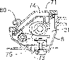
Accompanying drawing 4 and 9 clearly illustrates that the top cover 71 of the cam-operated chamber 21 upper shed faces of draught excluder links to each other with cylinder head 8 through an obturator 72.One is formed in the cylinder head 71 with the admission chamber 74 that this valve cam operation chamber 21 is communicated with through one group of hole 73,73.This admission chamber 74 has a flat pattern along valve cam operation chamber 21 upper surfaces, and has four holes 73,73 everywhere at its diapire.Long and short suction pipe 75 and 76 and the diapire of admission chamber 74 form whole in the central region of diapire, on the axial direction of camshaft 26, between this long and short suction pipe 75 and 76 interval is arranged,, and in this suction pipe 75 and 76, disposed hole 73 and 73 so that extend in the valve cam operation chamber 21.
Shown in Fig. 6 to 8, admission chamber 74 also is connected with the inside of fuel tank 40 through a return tube 78.This return tube 78 forms an integral body along the edge of belt housing 36 and belt housing 36, and in a side relative with transport pipe 60.As a whole from the supplying tube 79 that stretch out on the top of the return tube 78 of belt housing 36 back with 36 one-tenth of belt housings, and this supplying tube 79 links to each other with an output tube 80, this output tube 80 is formed in the top cover 71 by a connector 81, and supplying tube 79 is communicated with admission chamber 74 like this.
In addition, output tube that stretches out from the lower end of the return tube 78 of belt housing 36 back 82 forms an integral body with this belt housing 36, and this output tube 82 is assemblied in the return port 83 in the fuel tank 40, like this internal communication of output tube 82 and fuel tank 40.The opening end of return port 83 is positioned near the middle part of fuel tank 40, and like this, regardless of the working position of motor E, the opening end of return port 83 always is on the oil level in the fuel tank 40.
The driven part 84 that is driven by above-mentioned recoil type starter 42 is fixed on the front end of bent axle 13, and this bent axle 13 stretches out outside the fuel tank 40.
At motor E duration of work, the lubricant oil O that oil thrower 56 is scattered in the fuel tanks 40 owing to the rotation of bent axle 13, thereby generation mist of oil, and when the pressure that makes bent axle chamber 23 owing to moving upward of piston 15 reduces, the mist of oil of Chan Shenging enters into bent axle chamber 6a with regard to via through holes 55 like this, lubricated like this bent axle 13 and piston 15.When pressure among the bent axle chamber 6a is raise, one-way valve 61 is opened, the blow-by gas that the above-mentioned mist of oil of result produces in bent axle chamber 6a rises in the transport pipe 60, and offer valve cam operation chamber 21, like this camshaft lubrication 26, cam follower 24 and 25 etc.
When the mist of oil in the valve cam operation chamber 21 and blow-by gas enter gas-liquid split tunnel 68 in the rotating cam axle 26, gas is separated by centrifugal force with liquid in passage 68, liquid oil turns back in the valve cam operation chamber 21 through the transverse holes 68a of gas-liquid split tunnel 68, but in the aspirating stroke of motor E, blow-by gas is brought among the motor E through ventilation chamber 69, breathing pipe 70 and air-strainer 4.
As previously mentioned since valve cam operation chamber 21 through gas-liquid split tunnels 68, ventilation chamber 69 and breathing pipe 70 and with the internal communication of air-strainer 4, so the pressure in valve cam operation chamber 21 remains on or a shade below atmospheric pressure.
On the other hand, because the malleation component of pressure pulsation is discharged by one-way valve 61, the middle pressure among the bent axle chamber 6a is a negative value.This negative pressure passes to fuel tank 40 by hole 55, and further passes to admission chamber 74 by return tube 78.So the pressure in the admission chamber 74 is lower than the pressure in the valve cam operation chamber 21, the pressure in the fuel tank 40 is lower than the pressure in the admission chamber 74.The result, this pressure through suction pipe 75 and 76 and hole 73,73 be delivered to admission chamber 74 from valve cam operation chamber 21, and further be delivered to fuel tank 40 through return tube 78, along with this transmission, mist of oil in the valve cam operation chamber 21 and stay in the valve cam operation chamber 21 fluid oil by suction pipe 75 and 76 and hole 73,73 be inhaled in the admission chamber 74, and turn back in the fuel tank 40 by return tube 78.
As mentioned above, because four holes 73,73 are configured on four points of admission chamber 74 diapires, and hole 73 and 73 is configured in length, in the short suction pipe 74 and 75, this suction pipe extend into the valve cam operation chamber 21 from the diapire middle part, long, the direction at the interval between the short suction pipe 74 and 75 is perpendicular to the axial direction of camshaft 26, six holes 73, in 73 one is submerged and is stored in the fluid in the valve cam operation chamber 21, working position regardless of motor E, it for example is the state that makes progress (A) as shown in figure 10, left bank state (B), right bank state (C), left side configuration state (D), right configuration state (E) or inversion state (F), and oil can upwards be extracted in the admission chamber 74.
Owing to utilize the pressure pulsation of bent axle chamber 6a and the function of one-way valve 61, and the mist of oil that will produce in fuel tank 40 like this offers bent axle chamber 6a and the valve cam operation chamber 21 of OHC type four stroke engine E, and make it return fuel tank 40, the inside of motor E can be lubricated reliably by mist of oil, and no matter the working position of motor E how; In addition, do not need a special oil pump that mist of oil is circulated, like this can simplified structure.
Be not only the fuel tank of making by synthetic resin 6a 40, the transport pipe 60 of connection is provided between also promising crankshaft cavity chamber 6a and the valve cam operation chamber 21 and provides the return tube 78 that is communicated with all to be placed on outside the engine main body 1 between admission chamber 74 and the fuel tank 40, so can be to engine main body 1 not being done to such an extent that thinner smaller and more exquisite formation hinders, thus very help alleviating the weight of motor E.Especially, because external transport pipe 60 and return tube 78 be subjected to the heat affecting of engine main body 1 less, can prevent that lubricant oil O's is overheated.In addition, the global formation of transport pipe 60, return tube 78 and belt housing 36 helps reducing number of spare parts, thereby strengthens assembly performance.
Figure 11 has shown the embodiment of a change of transport pipe 60 and return tube 78, and in the case, transport pipe 60 and return tube 78 are all formed by the pipe that flexible material such as rubber are made, and they separate with belt housing 36.Because other part is same as the previously described embodiments, the part of correspondence is represented by identical label among the figure, and has omitted the explanation to it.
Improve embodiment according to this,, can pass through suitably crooked transport pipe 60 and return tube 78, just transport pipe 60 and return tube 78 freely can be assemblied on the tie point, can increase the degrees of freedom of layout like this regardless of the position of this tie point.
In the first above-mentioned embodiment, a rotary valve can also be provided rather than adopt one-way valve 61, this rotary valve operation ground is connecting bent axle 13 and operation like this, promptly opens transport pipe 60 when piston 15 descends, and block transport pipe 60 when piston 15 rises.
Below, with reference to Figure 12 to 24 second embodiment of the present invention is described.
Shown in Figure 12 and 13, vaporizer 102 and exhaust muffler 103 are connected to engine main body 101 front and rear portions of a kind of hand four stroke engine E, and air-strainer 104 is connected in the ingress of this vaporizer 102.A fuel tank 105 of being made by synthetic resin is connected in the lower surface of engine main body 101.Stretch out outside the engine main body 101 at the two ends of bent axle 113, an and side of fuel tank 140 close engine main bodies 101, and a recoil type starter 142 is installed on the outer surface of this fuel tank 140, and this starter can connect to transmission the driven part 184 that is fixed on the bent axle 113.
The cooling fan 143 of the wheel effect of also taking off is fixed on the other end of bent axle 113.One assembling is joined boss 146 (one of them is presented among Figure 12) and is formed on the outer surface of this cooling fan 143, and rotatably support one centrifugal 147 on each mounting boss 146.These centrifugal 147 together is fixed on the driving shaft 150 that will describe below one with brake drum 148, formed a cenrifugal brake 149, when the slewing rate of bent axle 113 surpasses predetermined value, this centrifugal 147 just is being pressed under its action of centrifugal force on the internal surface of this brake drum 148, and the output torque with bent axle 113 passes to driving shaft 150 like this.The diameter of cooling fan 143 is greater than the diameter of cenrifugal brake 149.
Be covered with engine main body 101 and do not comprise that the hood 151 of the annex of fuel tank 140 is fixed in position with respect to engine main body 101, and between hood 151 and fuel tank 105, dispose a cooling air inlet 119.Rotation by cooling fan 143 sucks air outside through this cooling air inlet 119 like this, for each part of motor E provides cooling.
One is gone the tip circle taper and is fixed on this hood 151 with the bearing support 158 of bent axle 113 coaxial lines, and bearing support 158 is supporting driving shaft 150 through bearing 159 in the identical mode of aforementioned first embodiment, and this driving shaft rotates the cutter C of trimmer T (see figure 1).
Because fuel tank 140 and starter 142 are configured in a side, and cooling fan 143 and cenrifugal brake 149 are configured in opposite side, engine main body 101 is mediated, weight balancing about motor E improves, the center of gravity of motor E can have been strengthened the manoeuvring performance of motor E so more near the middle part of engine main body 101.
In addition, because having cooling fan 143 than centrifugal 147 diameter larger diameter is fixed on the bent axle 113 between engine main body 101 and the cenrifugal brake 149, so can avoid owing to there being cooling fan 143 to make the size of motor E that any increase be arranged.
Structure below with reference to Figure 12 to 15 and Figure 16,20 and 21 pairs of these engine main bodies 101 and fuel tank 140 describes.
At Figure 12 in Figure 15, engine main body 101 comprises that a bent axle that bent axle chamber 106a arranged 106, one have the cylinder block 107 of casing bore 107a and one that a cylinder head 108 that combustion chamber 108a, steam inlet 109 and steam-expelling port 110 are arranged is arranged, this steam inlet and steam-expelling port are to combustion chamber 108a split shed, and a large amount of cooled blades 138 is formed on the outer surface of this cylinder block 107 and cylinder head 108.
The bent axle 113 that is contained among the bent axle chamber 106a is bearing on the left and right sides sidewall of crankcase 106 by ball bearing 114 and 114 '.In this case, left ball bearing 114 has a Sealing, and has disposed an oil sealing 117 in the place near right ball bearing 114 '.The piston 115 that is assemblied among the casing bore 107a is connected on the bent axle 113 in common mode by the numbers through connecting rod 116.
Fuel tank 140 and crankcase 106 left wall unitary mouldings, and make bent axle 113 pass fuel tank 140 at an end of seal ball bearing 114.The oil sealing 139 that bent axle 113 is passed is assembled in the outer wall of fuel tank 140.
Belt guide pipe 186 with flat cross section becomes an integral body with the top of fuel tank 140, and this belt guide pipe 186 is the top by the fuel tank 140 and upper and lower end of opening is arranged vertically.Near the extension of the bent axle 113 of the lower end of belt guide pipe 186 in the fuel tank 140, its upper end is as a whole with 108 one-tenth of cylinder heads, like this it and cylinder head 108 shared dividing plates 185.Article one, the seal washer 187 of annular forms along the upper end of belt guide pipe 186 and cylinder head 108, and dividing plate 185 reaches on the sealing packing ring 187.
Shown in Figure 16,20 and 21, the lower surface of top cover 136 formed one with above-mentioned seal washer 187 corresponding ring packing groove 188a, formed an interconnective linear sealed groove 188b in the both sides with ring packing groove 188a at the internal surface of lid 136.A ring liner 189a is assemblied among this ring packing groove 188a, and one becomes the linear liner 189b of an integral body to be assemblied among the linear sealed groove 188b with ring washer 189a.Top cover 136 links together by bolt 137 and cylinder head 108, and seal washer 187 and dividing plate 185 are pressed against respectively on ring liner 189a and the linear liner 189b like this.
Half of belt guide pipe 186 and top cover 136 formed first valve operation chamber 112a, and second half of cylinder head 108 and top cover 136 formed second valve operation chamber 121b, and these two valve operation chamber 121a and 121b are by above-mentioned dividing plate 185 separately.
Again referring to figs. 12 to 15, in an axis that comprises bent axle 133 and the plane perpendicular to the axis of casing bore 107a, engine main body 101 and fuel tank 140 are divided into unit B a and lower unit Bb.That is, last unit B a integrally comprises the first half of the first half, cylinder block 107, cylinder head 108, belt guide pipe 186 and the fuel tank 140 of crankcase 106.Lower unit Bb integrally comprises the Lower Half of axle 106 and the Lower Half of fuel tank 140.These upper and lower unit cast respectively, and after with the each several part machining, by one group of bolt 112 (seeing Figure 14) it are interconnected.
A steam inlet valve 118i and an exhaust steam valve 118e of being used for opening and closing steam inlet 109 and steam-expelling port 110 on cylinder head 108, have been disposed respectively, and make this two valve be parallel to the axis of casing bore 107a, and being screwed into a spark plug 120, its electrode is near the center region of combustion chamber 108a like this.
Below with reference to valve operating gear 122 that is used for opening and closing above-mentioned steam inlet valve 118i and exhaust steam valve 118e of Figure 13 to 17 explanation.
Valve operating gear 122 comprises an annular timing transmission device 122a and a camming 122b, this annular timing transmission device 122a operates chamber 121a transmission to first valve from fuel tank 140, and this camming 122b operates chamber 121b transmission from first valve operation chamber 121a to second valve.
This annular timing transmission device 122a comprises that one is fixed on the driving wheel on the bent axle 133 in the fuel tank 140 123, one and is rotatably supported in the follower 124 on belt guide pipe 186 tops and one and is wrapping initiatively and the Timing Belt 125 of follower 123 and 124.At the another side of dividing plate 185, the end face of follower 124 is linked to be an integral body with the cam 126 that becomes a camming 122b part.Driving wheel and follower 123 and 124 are toothed, and driving wheel 123 drives follower 124 by belt 125 with reduction speed ratio 1/2.
Abutment wall 127 forms an integral body with the outer wall of belt guide pipe 186, and this abutment wall upwards rises within ring packing packing ring 187 and contacts with the internal surface of top cover 136 or in its vicinity.Form a through hole 128a and a bottom outlet 128b on this abutment wall 127 and dividing plate 185 respectively, these two holes coaxially are configured on the seal washer 187.By the two ends of through hole 128a and bottom outlet 128b rotatably support supporting axle 129, and above-mentioned follower 136 and cam 126 are supported rotatably in the middle part of supporting axle 129.Before connecting top cover 136, supporting axle 129 is inserted in the axis hole 135 of follower 124 and cam 126 from through hole 128a, and insert among the bottom outlet 126b.After the insertion, top cover 136 is connected on cylinder head 108 and the belt guide pipe 186, like this, the internal surface of top cover 136 is in the position relative with the outer end of supporting axle 129, thereby play the effect of backstop, preventing that axle from 129 dropping out through hole 128a, and the inside motion of axle 129 has been limited in the bottom of bottom outlet 128b.Supporting axle 129 has been limited inside and outside motion on it is axial like this.
Therefore do not need to provide a special backstop part for supporting axle 129, this supporting axle 129 can be lubricated in top cover 136, can prevent leakage of oil by the oil seal joint between top cover 136 and the cylinder head 108, so just need on supporting axle 129, not connect a special obturator, thereby reduced number of spare parts, and reduced cost.In addition, through hole 128a whereabouts on the abutment wall 127 that rises in seal washer 187 is than the position height of seal washer 187, the internal surface of top cover 136 contacts with the outer surface of abutment wall 127 or in its vicinity, can do top cover 136 smaller and more exquisite like this, making supporting axle 129 simultaneously be dismountable before connecting top cover 136.
A pair of as a whole with 185 one-tenth on dividing plate with 130e in the side of second valve operation chamber 121b with the axle 129 bearing boss 130i that stretch out abreast.Camming 122b comprises above-mentioned cam 126; Be rotatably supported in an admission rocker shaft 131i and a steam discharge rocker shaft 131e in above-mentioned bearing boss 131i and the 131e respectively; Be separately fixed at the admission cam follower 132i and the steam discharge cam follower 132e of the end of rocker shaft 133i and 133e in first valve operation chamber 121a, the front end of admission cam follower 132i and steam discharge cam follower 132e contacts slidably with the lower surface of cam 126 respectively; The admission rocker arm 133i and the steam discharge rocker arm 133e of the other end in second valve operation chamber 121b, that be separately fixed at admission rocker shaft 133i and steam discharge rocker shaft 133e, the front end of each admission rocker shaft 133i and steam discharge rocker shaft 133e contacts with the upper end of each admission valve 118i and exhaust valve 118e; Be installed in admission valve 118i and exhaust valve 118e respectively and go up and oppress the admission spring 134i and the steam discharge spring 134e of this two valve at closing direction.
When bent axle 113 rotates, the driving wheel 123 that rotates with bent axle 113 drives follower 124 and cam 126 rotations by belt 125, cam 126 is with the suitable timing swing admission cam and the driven member 132i and the 132e of steam discharge cam then, oscillating motion passes to admission and steam discharge rocker arm 133i and 133e through corresponding rocker shaft 131i and 131e, like this Bai Dong admission and steam discharge rocker arm 133i and 133e just can with admission and steam discharge spring 134i and 134e collaborative work, open and close admission valve 118i and exhaust valve 118e with suitable timing.
In timing transmission device 122a, because follower 124 and cam 126 are by supporting axle 129 rotatably supports, and supporting axle 129 be to be rotatably supported on two sidewalls of first valve operation chamber 121a, supporting axle 129 also rotates owing to friction drives when follower 124 and cam 126 rotations, speed discrepancy between supporting axle 129 and follower 124 and the cam 126 is reduced, thereby has suppressed the wearing and tearing of rotation and sliding area.Thereby need not any special material or surface treatment, just can prolong the life-span of cam 126 and supporting axle 129.
Have larger-diameter cam 126 and be placed on a side of cylinder head 108, just in time be placed on the cylinder head 108 and have only relatively than the admission rocker arm 131i of minor diameter and 131e and admission rocker shaft 131i and 131e with follower 124.Therefore valve operating gear 122 does not occupy very big space, cylinder head 108 tops, so just can reduce the total height of whole motor E, thereby make that this motor E is smaller and more exquisite.
In addition, upper end at cylinder head 108 and belt guide pipe 186, supporting axle 129 and admission rocker shaft 131i and steam discharge rocker shaft 131e are positioned at the position higher than ring packing packing ring 187, therefore, under the state that removes top cover 136, just can make I﹠ M very easy without any hindering ground mounting or dismounting supporting axle 129 and admission and steam discharge rocker shaft 131i and 131e on seal washer.
Lubrication system below with reference to Figure 13 to 22 couple of above-mentioned motor E describes.
Shown in Figure 14 and 15, fuel tank 140 has stored the lubricant oil O of the predetermined quantity that injects by a filler opening 140a.In fuel tank 140, a pair of oil thrower 156a and the 156b that are configured in driving wheel 123 both sides in the axial direction are press fitted on the bent axle 131.These two oil thrower 156a and 156b are radially extending on the opposite directions, and its front end in the axial direction mutually away from direction on crooked, like this when this oil thrower is rotated by bent axle 113, have at least one to stir and scatter the oily O that exists in the fuel tank 140 among two oil thrower 156a and the 156b, regardless of the working position of motor E, all can produce mist of oil like this.In the case, mist of oil is splashed to from the first valve operation chamber 121a and extends on the part of the timing transmission device 122a the fuel tank 140, perhaps mist of oil enters the first valve operation chamber 121a, and timing transmission device 122a just can directly be lubricated, and a lubrication system so just is provided.
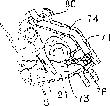
As Figure 13 to 15 and shown in Figure 22, another lubrication system comprises and being configured on the bent axle 113 so that for a through hole 155 of connection is provided between the inside of fuel tank 140 and the bent axle chamber 106a; One is configured in outside the engine main body 101 so that connect the transport pipe 160 of the bent axle chamber 106a bottom and the second valve operation chamber 121b bottom; One is configured in outside the cylinder head 108 so that aspirate the oil recovery chamber 174 of fluid oil among the second valve operation chamber 121b; One is formed between cylinder head 108 and the fuel tank 140 so that the drainback passage 178 of connection is provided for oil recovery chamber 174 and fuel tank 140 through the first valve operation chamber 121a; One is configured in the bottom of bent axle chamber 106a and only allows mist of oil flow to the one-way valve 161 of transport pipe 160 from bent axle chamber 106a.
An opening end 155a of the above-mentioned through hole in fuel tank 140 155 be positioned at the middle part of fuel tank 104 or in the middle near, regardless of the working position of motor E, opening end 155a always is on the liquid level of the oily O in the fuel tank like this.Driving wheel 123 and an oil thrower 156a are fixed on the bent axle 113, make opening end 155a between them, thereby can not hinder opening end 155a.
In an illustrated embodiment, above-mentioned one-way valve 161 (seeing Figure 13) comprises a needle-valve.When the to-and-fro motion of following piston 115, when making pressure among the bent axle chamber 106a become negative value, this valve closing, and when this pressure become on the occasion of the time, this valve open.
By transport pipe 160 small ends being assembled to the lower end that connects transport pipe 160 on the following connecting tube 162a that stretches out crankcase 106 (seeing Figure 13) outer surface, by transport pipe being assembled to the upper end that is connected transport pipe 160 on the last connecting tube 182b that stretches out cylinder head 108 (seeing Figure 14 and Figure 18) outer surface.The inboard of last connecting tube 182b is communicated with the bottom of the second valve operation chamber 121b through a connecting passage 163 that is formed on the cylinder head 108 and has large-size (seeing Figure 18 and Figure 19), and opposite side is communicated with drainback passage 178 through a bypass 164 with holes (seeing Figure 18).
Shown in Figure 15,20 and 21, adopt one group of supporting strut 166 and be fixed on intermediate plate 167 on this supporting strut, the dividing plate 165 that will define the chamber 169 of ventilating on the top of top cover 136 is fixed on and covers 136 top, and this strut 166 stretches out from the top.One side of ventilation chamber 169 is communicated with the second valve operation chamber 121b through the gap g between the internal surface of a connecting tube 168 and top cover 136 and the dividing plate 165, and 165 one-tenth on the connecting tube 168 that large-size arranged and dividing plate are as a whole and extend towards the second valve operation chamber 121b.Ventilation chamber 169 also at its opposite side through a breathing pipe 170 internal communication with above-mentioned air-strainer 104.In ventilation chamber 169, the mixture of oil and blow-by gas is separated into gas and liquid, and one promotes the mazy type wall 172 of vapor-liquid separation to stretch out the internal surface at the top of top cover 136.
The dividing plate 179 of a box-like is welded on the dividing plate 165, this box-like dividing plate 179 has an open surface, see that from top to bottom it is shaped as T shape, formed above-mentioned oil in the space of this box-like dividing plate 179 more than dividing plate 165 upper surfaces and reclaimed chamber 174, so should oil recovery chamber 174 also be T shape.
Two suction pipes 175 are as a whole with 165 one-tenth on dividing plate, so just stretch from dividing plate, and these two suction pipes 175 are communicated with respectively with the two ends that T shape oil reclaims the transverse bar of chamber 174.The front end of each suction pipe 175 reaches near the bottom of second valve operation chamber 121b, and the opening of each suction pipe 175 in the end formed hole 175a.
The upper wall of three suction pipes 176 becomes as a whole, stretches out from dividing plate 179 like this, and these three suction pipes 176 are connected with three corresponding positions that corresponding oil reclaims the horizontal and vertical boom end of T shape of chamber 174.Each end of these suction pipes 176 is stretched near the top of ventilation chamber 169, and each suction pipe 176 forms a hole 176a at the opening of end sections.
In addition, disposed a hole 180 in the upper wall of partition box 179, this hole 180 makes groove 179a be connected with the upper surface and the oil recovery chamber 174 of partition box 179.
In addition, the pipe 181 that is connected of the zone of the T shape longitudinal rod end of an oily recovery tube 174 of correspondence is as a whole with 165 one-tenth on dividing plate.The end of pipe 181 is assemblied in by a grommet 182 among the inlet 178a of above-mentioned oily recovery approach 178, and this inlet 178a opens the bottom at the second valve operation chamber 121b.This oil reclaims chamber 174 and just links to each other with drainback passage 178 like this.Above-mentioned pipe 181 is near the internal surface of the second valve operation chamber 121b, and a hole 181a who is used for oil suction is provided in the zone near above-mentioned internal surface, and this hole 181a is communicated with the second valve operation chamber 121b and pipe 181.
Because ventilation chamber 169 is through the internal communication of breathing pipe 170 with air-strainer 104, even so in motor E working procedure, the pressure of ventilation in the chamber 169 remains barometric pressure basically, and the pressure among the connecting tube 168 by having low flow resistance and the second valve operation chamber 121b that this vent is communicated with basically with the chamber 169 of ventilating in pressure identical.
In the working procedure of motor E, because bent axle chamber 106a only discharges the malleation component that produces owing to 115 of piston moves up and down in transport pipe 160 by one-way valve 161, so pressure average out to negative value among the bent axle chamber 106a, again owing to accept the second valve operation chamber 121b of above-mentioned malleation and be communicated with ventilation chamber 169, so the pressure among the second valve operation chamber 121b is almost identical with pressure in the chamber 169 of ventilating through connecting tube 168 with low flow resistance.Because the through hole 155 of negative pressure on bent axle 113 of bent axle chamber 106a is passed to fuel tank 140, and further being delivered to oil through drainback passage 178 reclaims in the chamber 174, so, pressure in the oil recovery chamber 174 is lower than the pressure in the second valve operation chamber 121b and the ventilation chamber 169, and the pressure among the fuel tank 140 and the first valve operation chamber 121a is lower than the oily pressure that reclaims in the chamber 174.
As shown in figure 22, pressure representative in bent axle chamber 106a is Pc, pressure representative in the fuel tank 140 is Po, pressure representative among the first valve operation chamber 121a is Pva, pressure representative among the second valve operation chamber 121b is Pvb, the pressure representative that oil reclaims in the chamber 174 is Ps, when the pressure representative in the ventilation chamber 169 is Pb, can satisfy following relation:
Pvb=Pb>Ps>Po=Pva>Pc
As a result, the pressure in the second valve operation chamber 121b and the ventilation chamber 169 is passed to oil through suction pipe 175 and 176 and reclaims in the chamber 174, and is delivered in the fuel tank 140 through drainback passage 178, is delivered to subsequently among the bent axle chamber 106a.
In motor E working procedure, produce mist of oil by oil thrower 156a and the 156b that in fuel tank 140, stirs and scatter lubricant oil O, oil thrower 156a and 156b are driven by bent axle 112.As mentioned above, the mist of oil of Chan Shenging is splashed on that part of timing transmission device 122a that is exposed to from belt guide pipe 186 in the fuel tank 140 like this, be on the Timing Belt 125 of driving wheel 123 and part, perhaps mist of oil enters into the first valve operation chamber 121a, thereby directly lubricated timing transmission device 122a.Even when oil droplet was splashed on the timing transmission device 122a, oil not only can be passed on the whole transmission device 122a, can also be delivered on the cam 126 owing to the operation of this timing transmission device 122a, thus lubricated effectively these parts.
The mist of oil that produces in fuel tank 140 is inhaled among the 106a of axocoel chamber along the direction that above-mentioned pressure flows through the through hole 155 on the bent axle 113, the lubricated like this zone that surrounds bent axle 113 and piston 115.When the decline owing to piston 115 make pressure among the bent axle chamber 106a become on the occasion of the time, one-way valve 161 is opened, and the mist of oil among the above-mentioned crankshaft cavity 106a up passes through transport pipe 160 and connecting passage 163 together with blow-by gas, and offer the second valve operation chamber 121b, each part of camming 122b among the lubricated like this chamber 121b, i.e. admission and steam discharge rocker arm 133i and 133e etc.
In the case, a part of mist of oil by above-mentioned connecting passage 163 is diverted in the drainback passage 178 through hole shape bypass 164.Therefore, can control the mist of oil amount of supplying with the second valve operation chamber 121b by the flow resistance of suitable setting bypass 164.
When being transported to ventilation chamber 169 by the gap around connecting tube 168 and the dividing plate 165, mist of oil and blow-by gas among the second valve operation chamber 121b are separated into liquids and gases by expansion in mazy type wall 172 and collision, in the aspirating stroke of motor E, blow-by gas enters in motor E and the air-strainer 104 successively through breathing pipe 170.
Because when motor E is upright, the fluid oil of ventilation in the chamber 169 stayed among the groove 179a of partition box 169 upper surfaces or flowed into connecting tube 168 or stay the bottom of the second valve operation chamber 121b by gap g, reclaims in the chamber 174 so hole 180 by herein or suction pipe 175 oil are drawn onto oil.Because when motor E is in inversion state, above-mentioned fluid oil is stayed the top of top cover 136, and the suction pipe 176 by herein is drawn into oil in the oil recovery chamber 174.
The oil that sucks oil recovery chamber 174 like this returns in the fuel tank 140 through pipe 181 and drainback passage 178.In the case, when drainback passage 178 when embodiment is communicated with fuel tank 140 through the first valve operation chamber 121a like that as shown, the oil of discharging from drainback passage 178 is splashed on the timing transmission device 122a, so easily it is lubricated.
Because above-mentioned ventilation chamber 169 is limited at the top of top cover 136 and is connected between the dividing plate 165 on top cover 136 inwalls, and above-mentioned oil reclaims chamber 174 and is limited at aforementioned barriers 165 and is welded between the partition box 179 on the dividing plate 165, so oil reclaims chamber 174 and ventilation chamber 169 can be configured in the top cover 136, and needn't separate the top of top cover 136.In addition, because reclaiming chamber 174, ventilation chamber 169 and oil is present in the top cover 136, even there are some oil from chamber 169 and 174, to spill, these oil are also with regard to being easy to get back among the second valve operation chamber 121b and can not cause any problem, so do not need to check whether oil seal of two chambers 169 and 174, thereby can reduce production costs.
Owing to partition box 179 just can be welded on the dividing plate 165 before dividing plate 165 is connected on the top cover 136, be easy to be formed in the dividing plate 165 so oil reclaims chamber 174.
Because oily suction pipe 175 and 176 is integrally formed with dividing plate 165 and partition box 179 respectively, therefore oily suction pipe 175 and 176 is easy to be shaped.
When the inversion state that is in as shown in figure 23, the oily O in the fuel tank 140 is towards the top motion of fuel tank 140, promptly towards the lateral movement of the first valve 121a.Owing to make the opening end of the valve operation chamber 121a that wins be higher than the liquid level of oil in reserve O by belt guide pipe 186, so can prevent oil in reserve O enters among the second valve operation chamber 121b, thereby can prevent too much oil offers prearranging quatity in timing transmission device 122a and the maintenance fuel tank 140 oil, so just can allow oil thrower 156a and 156b produce mist of oil continuously.
As motor E in the course of the work as shown in figure 24 like that during side, oil in reserve O is towards the side surface motion of fuel tank 140.Yet, owing to make the opening end of the valve operation chamber 121a that wins be higher than the liquid level of oil in reserve O by belt guide pipe 186, so can prevent oil in reserve O enters among the second valve operation chamber 121b, thereby can prevent too much oil offers prearranging quatity in timing transmission device 122a and the maintenance fuel tank 140 oil, so just can allow oil thrower 156a and 156b produce mist of oil continuously.
An oil droplet guide wall 190 (seeing Figure 15 and 24) is as a whole with 140 one-tenth of fuel tanks, and stretch out from the inwall of this fuel tank 140, this oil droplet guide wall 190 is facing to the upper side 125a of the Timing Belt 125 of timing transmission device 122a, and this Timing Belt 125 moves from the master end towards slave end around driving wheel 123.
The result, motor E by the upper side 125a of side and Timing Belt 125 from the master end when slave end carries out horizontal motion basically, even when the oil in reserve O in the fuel tank 140 is present under the Timing Belt 125, also can produce a part of mist of oil by being connected oil thrower 156a on the oil droplet guide wall 190 and the rotation of 156b, oil accumulation gets up to form Timing Belt 125 tops that oil droplet O` flows to the master end, be with in follower 124 1 sides at the oil droplet O` of Timing Belt 125 upside 125a, it can be subjected to any influence of centrifugal force hardly, meanwhile, oil droplet O` lubricates follower 124 so reliably around the back motion of upside 25a.
In the case, if there is not oil droplet guide wall 190, most of mist of oil that oil thrower 156a and 156b produce is attached to the downside of Timing Belt 125, when owing to Timing Belt 125 downsides upwards lateral movement when having produced centrifugal force by driving wheel 123 rotating drive, oil droplet separates with Timing Belt 125, and mist of oil is difficult to reach the slave end of Timing Belt 125 like this.
The lubrication system of valve operating mechanism 122 can be divided into two parts like this, promptly, part lubrication system is with being dispersed in that oil in the fuel tank 140 lubricate the part of camming 122b and in the first valve operation chamber 121 and the timing transmission device 122a in the fuel tank 140, and some lubrication system is lubricated that part in the second valve operation chamber 121b that camming is left with the mist of oil that is delivered among the second valve operation chamber 121b.Load on the lubrication system each several part is reduced like this, and whole valve operating mechanism 122 can obtain lubricated completely.In addition, regardless of the working position of motor E, the each several part of motor E also can carry out lubricated reliably with oil droplet and mist of oil.
Come circuit owing to be created in mist of oil in the fuel tank 140 and be the pressure pulse that utilizes among the bent axle chamber 106a and the one-way transmission function of one-way valve 161, do not need to adopt a special oil pump that oil is circulated, so structure can be simplified.
Be not only fuel tank, and the transport pipe 160 that is communicated with the bent axle chamber 106a and the second valve operation chamber 121b in addition all is configured in outside the engine main body 101, therefore can engine main body 101 be done to such an extent that alleviate the weight of motor E under the thinner smaller and more exquisite prerequisite widely not influencing.The cooling of the mist of oil by this transport pipe 160 particularly because external transport pipe 160 seldom is subjected to the influence of the heat that engine main body 101 produced, and can be easy to heat radiation, so can improve.
In addition, because fuel tank 140 places the outside of engine main body 101, the total height of motor E can reduce widely, and because the part of timing transmission device 122a is in fuel tank 140, so that the width increase of motor E is reduced to minimum, therefore make motor E smaller and more exquisite.
Below, will describe with reference to Figure 25 to the 36 pair of third embodiment of the present invention.
The external structure of hand four stroke engine E will illustrate with reference to Figure 25 and 26.
Vaporizer 202 and exhaust muffler 203 are connected to the front and back of the engine main body 201 of above-mentioned hand four stroke engine, and an air-strainer 204 is connected the inlet of vaporizer 202.A fuel tank 205 of being made by synthetic resin is connected the lower surface of engine main body 201.Stretch out outside the engine main body 201 at the two ends of bent axle 213, and a side of fuel tank 240 close engine main bodies 201, a recoil type starter 242 that is connected on the driven part 284 that is fixed in bent axle 213 1 ends is connected with the outer surface of fuel tank 240 with also having transmission.
The cooling fan 243 of the wheel effect of also taking off is fixed on the other end of bent axle 213.One assembling is joined boss 246 (one of them is presented among Figure 25) and is formed on the outer surface of cooling fan 243, and rotatably support centrifugal 247 on each mounting boss 246.These centrifugal 247 following with the brake drum 248 on the driving shaft of describing 250 with being fixed on, formed a cenrifugal brake 249, when the slewing rate of bent axle 213 surpasses predetermined value, because centrifugal centrifugal action, just be pressed against for centrifugal 247 on the internal surface of brake drum 248, the moment of torsion with bent axle 213 outputs is delivered on the driving shaft 250 like this.The diameter of cooling fan 243 is bigger than the diameter of cenrifugal brake 249.
Covering engine main body 201 and annex do not comprise that the hood 251 of fuel tank 240 is fixed on the appropriate location of engine main body 201, and a cooling air inlet is configured between hood 251 and the fuel tank 205.Each several part for motor E provides cooling to the air of outside by the rotation of fan 243 through cooling air inlet 219 like this.
One is fixed on the hood 251 with the coaxial tip circle axis of cone bearing 258 of going of bent axle 213, and this bearing support 285 is supporting driving shaft 250, and this driving shaft 250 rotates cutter C on the trimmer T (see figure 1) in the mode identical with above-mentioned first embodiment through bearing 259.
Cooling fan 243 and cenrifugal brake 249 are configured in opposite side because fuel tank 240 and starter 242 are configured in a side, and engine main body 201 is outer in the centre, the weight balancing of motor E around side improves, motor E center of gravity can have been strengthened the manoeuvring performance of motor E like this near the middle part of engine main body 201.
In addition,, be between engine main body 201 and the cenrifugal brake 249, therefore can avoid the size increase of the motor E that causes owing to cooling fan 243 because diameter is fixed on the bent axle 213 greater than the cooling fan 243 of centrifugal 247 diameter.
The structure of engine main body 201 and fuel tank 240 will be described with reference to Figure 25 to 28,29,32 and 33 below.
In Figure 25 to 28, engine main body 201 comprises that the bent axle 206 of a band crankcase 206a, cylinder block 207 that has a casing bore 207a and one have combustion chamber 208a and to the cylinder head 208 of the steam inlet of this combustion chamber 208a opening and steam-expelling port 209 and 210 be formed at a large amount of cooled blade 238 on cylinder block 207 outer surfaces and the cylinder head 208.
The bent axle 213 that is contained in bent axle chamber 206a is bearing on the left and right sides sidewall of crankcase 206 by ball bearing 214 and 214`.In the case, the ball bearing 214 on the left side has a Sealing, and the outside of oil sealing 217 and the right ball bearing 214` joins.A piston 215 that is assemblied among the casing bore 207a is connected on the bent axle 213 in common mode by the numbers through connecting rod 216.
Fuel tank 240 becomes as a whole with the left side wall of crankcase 206, and passes fuel tank 240 at the bent axle 213 of seal ball bearing 214 those ends.One allows bent axle 213 be assemblied in the outer wall of fuel tank 240 by its oil sealing that turns round 239.
Belt guide pipe 286 with flat cross section becomes an integral body with the bottom of fuel tank 240, and this belt guide pipe 286 is the bottom by the fuel tank 240 and upper and lower end of opening is arranged vertically.Near the extension of the bent axle 213 of the lower end of belt guide pipe 286 in the fuel tank 240, its upper end is as a whole with 208 one-tenth of cylinder heads, like this it and cylinder head 208 shared dividing plates 285.Article one, the seal washer 287 of annular forms along the upper end of belt guide pipe 286 and cylinder head 208, and dividing plate 285 reaches on the sealing packing ring 287.
Shown in Figure 29,32 and 33, the lower surface of top cover 236 formed one with above-mentioned seal washer 287 corresponding ring packing groove 288a, formed an interconnective linear sealed groove 288b in the both sides with ring packing groove 288a at the internal surface of lid 236.A ring liner 289a is assemblied among this ring packing groove 288a, and one becomes the linear liner 289b of an integral body to be assemblied among the linear sealed groove 288b with ring washer 289a.Top cover 236 links together by bolt 237 and cylinder head 208, and seal washer 287 and dividing plate 285 are pressed against respectively on ring liner 289a and the linear liner 289b like this.
Half of belt guide pipe 286 and top cover 236 formed first valve operation chamber 221a, and second half of cylinder head 208 and top cover 236 formed second valve operation chamber 221b, and these two valve operation chamber 221a and 221b are by above-mentioned dividing plate 285 separately.
Again with reference to Figure 25 to 28, in an axis and the plane perpendicular to casing bore 207a axis that comprises bent axle 233, engine main body 201 and fuel tank 240 are divided into unit B a and lower unit Bb.That is, last unit B a integrally comprises the first half of the first half, cylinder block 207, cylinder head 208, belt guide pipe 286 and the fuel tank 240 of crankcase 206.Lower unit Bb integrally comprises the Lower Half of axle 206 and the Lower Half of fuel tank 240.These upper and lower unit cast respectively, and after with the each several part machining, by one group of bolt 212 (seeing Figure 27) it are interconnected.
A steam inlet valve 218i and an exhaust steam valve 218e of being used for opening and closing steam inlet 209 and steam-expelling port 210 on cylinder head 208, have been disposed respectively, and make this two valve be parallel to the axis of casing bore 207a, and a spark plug 220 is screwed into, its electrode is near the center region of combustion chamber 208a like this.
Below with reference to valve operating gear 222 that is used for opening and closing above-mentioned steam inlet valve 218i and exhaust steam valve 218e of Figure 26 to 30 explanation.
Valve operating gear 222 comprises a timing transmission device 222a and a camming 222b, this annular timing transmission device 222a operates chamber 221a transmission to first valve from fuel tank 240, and this camming 222b operates chamber 221b transmission from first valve operation chamber 221a to second valve.
This timing transmission device 222a comprises that one is fixed on the driving wheel on the bent axle 233 in the fuel tank 240 223, one and is rotatably supported in the follower 224 on belt guide pipe 286 tops and one and is wrapping initiatively and the Timing Belt 225 of follower 223 and 224.At the another side of dividing plate 285, the end face of follower 224 is linked to be an integral body with the cam 226 that becomes a camming 222b part.This cam 226 is placed on a side of cylinder head 208 like this with follower 114.Driving wheel and follower 223 and 224 are toothed, and driving wheel 223 drives follower 224 by belt 225 with reduction speed ratio 1/2.
Abutment wall 227 forms an integral body with the outer wall of belt guide pipe 286, and this abutment wall upwards rises within ring packing packing ring 287 and contacts with the internal surface of top cover 236 or in its vicinity.By a through hole 228a and bottom outlet 228b who on abutment wall 227 and dividing plate 285, forms respectively, the two ends of rotatably support supporting axle 229, and above-mentioned follower 236 and cam 226 are rotatably supported in the middle part of supporting axle 229.Before top cover 136 is installed, supporting axle 229 is inserted in the axis hole 235 of follower 224 and cam 226 from through hole 228a, and insert among the bottom outlet 226b.After the insertion, top cover 236 is connected on cylinder head 208 and the belt guide pipe 286, like this, the internal surface of top cover 136 is in and relative position, supporting axle 129 outer ends, like this supporting axle 229 is played the effect of backstop.
A pair of as a whole with 285 one-tenth on dividing plate with 230e in the side of second valve operation chamber 221b with the axle 229 bearing boss 230i that stretch out abreast.Camming 222b comprises above-mentioned cam 226; Be rotatably supported in an admission rocker shaft 231i and a steam discharge rocker shaft 231e on above-mentioned bearing boss 231i and the 231e respectively; An admission cam follower 232i and a steam discharge cam follower 232e who in first valve operation chamber 221a, is separately fixed at rocker shaft 233i and 233e one end, the front end of admission cam follower 232i and steam discharge cam follower 232e contacts slidably with the lower surface of cam 226 respectively; In second valve operation chamber 221b, an admission rocker arm 233i and a steam discharge rocker arm 233e who is separately fixed at the admission rocker shaft 233i and the steam discharge rocker shaft 233e the other end, the front end of each admission rocker shaft 233i and steam discharge rocker shaft 233e contacts with the upper end of each admission valve 218i and exhaust valve 218e; Be installed in admission valve 218i and exhaust valve 218e respectively and go up and oppress the admission spring 234i and the steam discharge spring 234e of this two valve at closing direction.
Supporting axle 229 and admission, steam discharge rocker arm 231I, 231e are positioned on the ring packing packing ring 287 and belt guide pipe 286 of cylinder head 208 upper ends.
When bent axle 213 rotates, the driving wheel 223 that rotates with axle 212 rotates follower 224 and cam 226 by belt 225, cam 226 is with the suitable timing swing admission cam and the driven member 232i and the 232e of steam discharge cam then, oscillating motion passes to admission and steam discharge rocker arm 233i and 233e through corresponding rocker shaft 231i and 231e, like this Bai Dong admission and steam discharge rocker arm 233i and 233e just can with admission and steam discharge spring 234i and 234e collaborative work, open and close admission valve 218i and exhaust valve 218e with suitable timing.
In timing transmission device 222a, because follower 224 and cam 226 are by supporting axle 229 rotatably supports, and supporting axle 229 also is rotatably supported on two sidewalls of first valve operation chamber 221a, supporting axle 229 also rotates owing to friction drives when follower 224 and cam 226 rotations, speed discrepancy between supporting axle 229 and follower 224 and the cam 226 reduced, thereby owing to the wearing and tearing of rotation that has suppressed and sliding area prolong the life-span.
Have larger-diameter cam 226 and be placed on a side of cylinder head 208, just in time be placed on the cylinder head 208 and have only relatively than the admission rocker arm 231i of minor diameter and 231e and admission rocker shaft 231i and 231e with follower 224.Therefore valve operating gear 222 does not account for very big space above cylinder head 208, so just can reduce the total height of whole motor E, thereby make that this motor E is smaller and more exquisite.
In addition, upper end at cylinder head 208 and belt guide pipe 286, supporting axle 229 and admission rocker shaft 231i and steam discharge rocker shaft 231e are positioned at the position higher than ring packing packing ring 287, therefore, under the state that removes top cover 236, just can make I﹠ M very easy without any hindering ground mounting or dismounting supporting axle 229 and admission and steam discharge rocker shaft 231i and 231e on seal washer.
Lubrication system below with reference to Figure 26 to 34 couple of above-mentioned motor E describes.
Shown in Figure 27 and 28, the lubrication system of motor E comprises one first lubricated partial L a and one second lubricated partial L b, wherein the first lubricated La is used for lubricated bent axle 213 zone on every side, be bent axle 213, bearing 214 and 214`, connecting rod 216, piston 215 etc., the second lubricated partial L b is used for lubricating valve operation chamber 222.The lubricant oil O of fuel tank 240 storing predetermined amounts, it enters by oil inlet hole 240a.Lubricated partial L a and Lb share above-mentioned fuel tank 240.Being configured in a pair of oil thrower 256a of driving wheel 223 both sides and 256b in the axial direction is pressed into and is assembled on the bent axle 231.These two oil thrower 256a and 256b are radially extending on the opposite directions, and its front end in the axial direction mutually away from direction on crooked, like this when this oil thrower is rotated by bent axle 213, have at least one to stir and scatter the oily O that exists in the fuel tank 240 among two oil thrower 256a and the 256b, regardless of the working position of motor E, all can produce mist of oil like this.
The first lubrication system La comprises one first oily passage 260
1With one second oily passage 260
2With an one-way valve 261, the first oily passage 260 wherein
1Pass bent axle 213 and the inside of fuel tank 230 is communicated with bent axle chamber 206a, and the second oily passage 260
2Make the bottom of bent axle chamber 206a and the internal communication of fuel tank 240, one-way valve 261 is configured in the second oily passage 260 among the bent axle chamber 206a
2Opening.Be accompanied by the to-and-fro motion of piston, the pressure among the bent axle chamber 206a raises or reduces, and first one-way valve 261 is closed thereupon and opened.The first and second oily passages 260
1With 260
2Opening end 260 in fuel tank 240
1A and 260
2A is positioned as close to the middle part of fuel tank 240, simultaneously, regardless of the working position of motor E, all makes opening end 260
1A and 260
2A always is on the liquid level of oil in reserve O.
The second lubrication system Lb comprises one the 3rd oily passage 260
3, oil reclaim chamber 274, the 4th an oily passage 260
4, the second oily passage 260
2With one second one-way valve 262, the 3rd oily passage 260 wherein
3By engine main body 201, be communicated with the middle part of the first valve operation chamber 221a and the bottom of the second valve operation chamber 221b like this; Oil reclaims chamber 274 and is formed in the top cover 236, is communicated with second valve operation chamber 221b like this; The 4th oily passage 260
4In the configuration engine main body 201, be communicated with oil and reclaim chamber 274 and bent axle chamber 206a; Second one-way valve 262 is configured in the opening of the 3rd oily passage 2603 among the second valve operation chamber 221b.Along with piston 215 motion up and down respectively, the pressure among the bent axle chamber 206a reduces and increases, and second one-way valve 262 is closed thereupon and opened.
Shown in Figure 28,32 and 33, adopt one group of supporting strut 266 and be fixed on intermediate plate 267 on this supporting strut, the dividing plate 265 that will define the chamber 269 of ventilating on the top of top cover 236 is fixed on and covers 236 top, and this strut 266 stretches out from the top.One end of ventilation chamber 269 is by a big gap, i.e. connecting tube 286 (seeing Figure 32) between the internal surface on the surface of dividing plate 264 and top intercalation 236, be communicated with the second valve operation chamber 221b, the other end of ventilation chamber 269 is communicated with air-strainer 204 by a breathing pipe 270.In this ventilation chamber 269, the mixture of oil and blow-by gas is separated into gaseous state and liquid state.
On dividing plate 265, welded a box-like dividing plate 279, formed above-mentioned oil in this box-like dividing plate 279 space more than the upper surface of dividing plate 265 and reclaimed chamber 274.
One group of suction pipe 275 (wherein four in the embodiment who shows) is as a whole with 265 one-tenth on dividing plate, stretches out from this dividing plate like this, and each suction pipe 275 is separated from each other and is communicated with oil recovery chamber 274.Stretch out towards near the bottom of the second valve operation chamber 221b or its end of each suction pipe 275, and each of each suction pipe be open-ended to have formed a hole 275a.
One group of suction pipe 276 (wherein three in the embodiment who shows) is as a whole with 279 one-tenth on dividing plate, stretches out from this dividing plate like this, and each suction pipe 276 is separated from each other and is communicated with oil recovery chamber 274.Stretch out near the top of ventilation chamber 269 end of each suction pipe 276, and each of each suction pipe be open-ended to have formed a hole 276a.
In addition, hole 280 and 283 is configured in respectively on dividing plate 265 and the dividing plate box 279, and hole 280 and 283 is reclaimed with oil that chamber 274 is communicated with the second valve operation chamber 221b respectively and is communicated with ventilation chamber 269.
In addition, a pipe 281 that is connected with oil recovery chamber 274 is as a whole with 265 one-tenth on dividing plate, stretches out from this dividing plate like this.The end of pipe 281 is connected the 4th oily passage 260 with the 4th oily passage 2604 through a grommet 282
4The upper end open, so just stretch out from the bottom of the second valve operation chamber 221b.Thus oil reclaim chamber 274 just with the 4th oily passage 260
4Connect.
The function of the lubrication system of motor E will be described below.In the working procedure of motor E, because the oil thrower 256a that rotates with bent axle 213 and 256b stirs and thereby the oily O of scatter storage in fuel tank 240 produces mist of oil, so be full of mist of oil among the fuel tank 240 and the first valve operation chamber 221a that opens towards these fuel tank 240 tops.Therefore the timing transmission device 222a that is contained among the first valve operation chamber 221a is directly lubricated by mist of oil.
Owing to moving up and down of piston 215 reduces pressure repeatedly and increase, in bent axle chamber 206a pressure pulsation takes place like this.Be accompanied by this pressure pulsation, mist of oil in the fuel tank 240 is carried between fuel tank 240 and bent axle chamber 206a back and forth, and the zone around the oil mist lubrication bent axle 213 of importing bent axle chamber 206a, promptly lubricated bent axle 213, bearing 214,214`, connecting rod 216, piston 215 etc.Because the pressure of first one-way valve 261 in bent axle chamber 206a was closed when reducing, and open when pressure raises, and a part of malleation component in the pressure pulsation was through the second oily passage 260
2Be discharged in the fuel tank 240, when mist of oil was liquefied in bent axle chamber 206a and stays the bottom of this chamber 206a, this oil was through the second oily passage 260
2Together with above-mentioned malleation component, pushed back in the fuel tank 240.
Pressure pulsation among the bent axle chamber 206a also influences second one-way valve 262, the first valve operation chamber 221a and the 3rd oily passage 260 by fuel tank 240
3, and second one-way valve 262 closes when also the pressure in bent axle 206a reduces, and opens when pressure raises.When second one-way valve 262 was opened, the mist of oil in the fuel tank 240 was sent to the first valve operation chamber 221a, the 3rd oily passage 260 subsequently
3In the second valve operation chamber 221b.Meanwhile, mist of oil is lubricated timing transmission device 222a in the first valve operation chamber 221a, and lubricates camming 222b in the second valve operation chamber 221b.
Because the malleation component of the pressure pulsation of bent axle chamber 206a is discharged in the fuel tank 240 through first one-way valve 261, and the pressure average out to negative value among the bent axle chamber 206a, so through the 4th oily passage 260
4The pressure that the oil that is communicated with bent axle chamber 206a reclaims in the chamber 274 also becomes negative value.On the other hand, because ventilation chamber 269 is through the internal communication of breathing pipe 270 with air-strainer 204, even and when motor E works, the pressure of ventilation in the chamber 269 remains on barometric pressure substantially, so also be essentially barometric pressure through connecting tube 268 with pressure among the second valve operation chamber 221b that the chamber 269 of ventilating is connected.The result, the second valve operation chamber 221b and and the pressure of ventilation in the chamber 269 through suction pipe 275 and 276 and hole 280 and 283 be transported to oil and reclaim in the chamber 274, and the mist of oil in the second valve operation chamber 221b and ventilation chamber 269 also is transported to oil and reclaims in the chamber 274 along with the transfer of pressure.Particularly when motor E is in positive configuration state, in the second valve operation chamber 221b, be liquefied and stay the oil of its bottom, the suction pipe 275 of the bottom by abutting against the second valve operation chamber 221b is transported to oil and reclaims in the chamber 274.When motor E is in inversion state, ventilation is liquefied in the chamber 269 and to stay its bottom also be top cover 236 top oil, be transported to oil by the fuel sucking pipe 276 that abuts against top cover 236 tops and reclaim in the chamber 274.Reclaim the oil of recovery in the chamber 274 through the 4th oily passage 260 at oil like this
4Be transported among the bent axle chamber 206a, thus the zone around the lubricated bent axle 213.
Timing transmission device 222a and camming 222b with less relatively load are only lubricated by the mist of oil that imports to the first and second valve operation chamber 221a and the 221b from fuel tank 240, and the amount of lubricant oil is less relatively, can prevent over-lubrication.Lubricate by being recovered to the mist of oil and the liquefaction oil that reclaim in the chamber 274 after importing to the mist of oil the bent axle 206a from fuel tank 240 and lubricating camming 222b around the bent axle 213; The amount of lubricant oil is relatively large, so just can lubricate bent axle 213 zone on every side that is subjected to big load effectively.Owing to be according to around the bent axle 213 and valve operating mechanism 222 suffered load and it is lubricated, so circulation can reduce than the oil mass in the legacy system relatively with the oil mass that oily amount promptly is stored in the fuel tank 240, and fuel tank 240 so that whole motor E can do smaller and more exquisite lightlyer.
Because the mist of oil that produces in fuel tank 240 is to utilize the pressure pulsation among the bent axle chamber 206a and the unidirectional conveying function of first and second one- way valves 261 and 262 to carry out circuit, so do not need the special pump mist of oil that circulates, so structure can be simplified.
The blow-by gas that results from bent axle chamber 206a is through the first oily passage 260
1Be transported in the fuel tank 240, and through the first valve operation chamber 221a, the 3rd oily passage 260
3Be transported in the ventilation chamber 269 together with mist of oil with the second valve operation chamber 221b, they are separated into gas and liquid in the chamber 269 in ventilation, and with blow-by gas after oil separates in the aspirating stroke of motor E successively through breathing pipe 270 and air-strainer 204 and be inhaled among the motor E.
When motor E becomes inversion as shown in figure 35 or during as the side position of Figure 36, the oily O that is deposited in the fuel tank 240 is towards the top or the side surface motion of fuel tank 240.Yet, because by belt guide pipe 286, the opening end that feasible first valve towards fuel tank 240 is operated chamber 221a always is higher than the liquid level of oil in reserve O, thereby prevented that oil in reserve O from entering into the first valve operation chamber 221a, so just can prevent to supply with the oily excessive of timing transmission device 222a, and the oil that maintains prearranging quatity is in fuel tank 240, thereby allows oil thrower 256a and 256b produce mist of oil continuously.
Because fuel tank 240 is placed on the outside of engine main body 201, the total height of motor E can reduce widely, and because some timing transmission device 222a is contained in the fuel tank 240, so the width increase of motor E can be reduced to minimum, thereby make motor E smaller and more exquisite lighter.
In the 3rd above-mentioned embodiment, the 3rd oily passage 2603 is connected with the middle part of the first valve operation chamber 221a, still, and the 3rd oily passage 260
3Also can be connected with the top of the first valve operation chamber 221a.
The invention is not restricted to the embodiments described, and can change in many ways and do not break away from the spirit and scope of the invention.For example, each the above embodiments adopt the timing transmission device of belt shape, but also can adopt the timing transmission device of chain.