CN1201048C - Refining machine - Google Patents
Refining machine Download PDFInfo
- Publication number
- CN1201048C CN1201048C CNB011119225A CN01111922A CN1201048C CN 1201048 C CN1201048 C CN 1201048C CN B011119225 A CNB011119225 A CN B011119225A CN 01111922 A CN01111922 A CN 01111922A CN 1201048 C CN1201048 C CN 1201048C
- Authority
- CN
- China
- Prior art keywords
- paper pulp
- reduction machine
- rotor
- attritioning
- gap
- Prior art date
- Legal status (The legal status is an assumption and is not a legal conclusion. Google has not performed a legal analysis and makes no representation as to the accuracy of the status listed.)
- Expired - Lifetime
Links
- 238000007670 refining Methods 0.000 title abstract 3
- 229920001131 Pulp (paper) Polymers 0.000 claims description 51
- 230000004048 modification Effects 0.000 description 9
- 238000012986 modification Methods 0.000 description 9
- 230000001133 acceleration Effects 0.000 description 5
- 230000002349 favourable effect Effects 0.000 description 5
- 230000000694 effects Effects 0.000 description 2
- 239000000725 suspension Substances 0.000 description 2
- 238000009825 accumulation Methods 0.000 description 1
- 238000010276 construction Methods 0.000 description 1
- 238000006073 displacement reaction Methods 0.000 description 1
- 238000009826 distribution Methods 0.000 description 1
- 238000005516 engineering process Methods 0.000 description 1
- 230000012447 hatching Effects 0.000 description 1
- 239000007788 liquid Substances 0.000 description 1
- 238000004519 manufacturing process Methods 0.000 description 1
- 238000005086 pumping Methods 0.000 description 1
- 230000000630 rising effect Effects 0.000 description 1
- 239000002002 slurry Substances 0.000 description 1
- 238000009827 uniform distribution Methods 0.000 description 1
Images


Classifications
-
- D—TEXTILES; PAPER
- D21—PAPER-MAKING; PRODUCTION OF CELLULOSE
- D21D—TREATMENT OF THE MATERIALS BEFORE PASSING TO THE PAPER-MAKING MACHINE
- D21D1/00—Methods of beating or refining; Beaters of the Hollander type
- D21D1/20—Methods of refining
- D21D1/34—Other mills or refiners
- D21D1/38—Other mills or refiners with horizontal shaft
-
- D—TEXTILES; PAPER
- D21—PAPER-MAKING; PRODUCTION OF CELLULOSE
- D21D—TREATMENT OF THE MATERIALS BEFORE PASSING TO THE PAPER-MAKING MACHINE
- D21D1/00—Methods of beating or refining; Beaters of the Hollander type
- D21D1/20—Methods of refining
- D21D1/22—Jordans
Abstract
The invention refers to a refiner comprising a rotor and a stator with an inlet pipe 1 and a cylindrical or conical refining gap 3 between rotor 5 and stator 6. It is mainly characterised by the pulp feed channel 2, 7 extending in radial direction from the inlet pipe 1 up to the refining gap 3.
Description
Technical field
The present invention relates to a kind of second reduction machine that comprises a rotor and a stator, and between rotor and stator, have a feed pipe and cylindrical shape or conical attritioning gap.
Background technology
The second reduction machine of great majority construction at present all is (two) disk or conical design.The shortcoming of two disk refiners is to change along the relative velocity of the length in attritioning zone, high relatively idle running rate and the problem that makes rotor centering, and especially output is lower.The remarkable shortcoming of known conical second reduction machine is the pumping effect of difference.This can cause the output difficulty, and therefore needs to enlarge the groove in the attritioning zone, and this has just reduced edge length.Other shortcoming that may exist also has the relative displacement of these cuttves when being provided with being relative to each other, owing to the cause that bearing capacity occurs needs firm design, and the difficulty in changing the attritioning plate, this can cause high production cost.For example adopt US5, the cylindrical shape second reduction machine known in 813,618 can avoid occurring many these shortcomings, yet output may have those problems similar and that conical second reduction machine is occurred.
Summary of the invention
Therefore, the objective of the invention is to prevent that the shortcoming of known cylindrical shape and conical second reduction machine from taking place, also in order to allow higher output.
According to the present invention, a kind of second reduction machine is provided, it comprises a rotor and a stator, and have an inlet duct and a cylindrical shape or the conical attritioning gap between rotor and stator, it is characterized in that, the paper pulp transfer passage extends upwardly to the attritioning gap along radial direction from inlet duct, between inlet duct and attritioning gap, be provided with a disk, this disk has the inlet surface and the exit surface to circumferential extension of relative configuration, wherein the inlet surface of disk is the paper pulp stream rotor that radially inwardly leads, and the exit surface of disk radially outward leads paper pulp stream around the attritioning gap of the whole circumference of disk.
A favourable design of the present invention is characterized in that the paper pulp conveyance conduit has a rotation symmetric design.This causes the even and rotational symmetric attritioning gap that flow into.
Further useful improved being characterised in that of the present invention, the feed pipe that is connected on the paper pulp conveyance conduit is positioned on the axis consistent with rotor axis.Paper pulp just directly is delivered into the axis of second reduction machine like this, and this makes that paper pulp was partly quickened and provide on the other hand paper pulp distribution more uniformly in pipe before entering the paper pulp transfer passage on the one hand.
Useful design of the present invention is characterised in that and is provided with a cylindrical rotor.This rotor also can be the taper shape of widening along the pulp flow direction, perhaps as a possibility, can be a bell-shaped rotor that narrows down along the pulp flow direction.Therefore, can adopt the shape in the attritioning gap that meets given requirement.
The present invention also has favourable improvements to be characterised in that to be provided with a birotor.By adopting a birotor, promptly rotor can be columnar also can be conical (widening taper or the taper that narrows down), just might obtain a high yield, can also acquire the rotational symmetric even inflow on the attritioning gap.
The present invention also has favourable improvements to be characterised in that the paper pulp transfer passage is between two rotors.Especially, if adopt feed pipe is located in the axis of rotor, the paper pulp center that just can be sent to second reduction machine is outwards derived by rotatablely moving then so, and this can cause the corresponding rising of pressure.The paper pulp in more downstreams is sent to the center in corresponding attritioning gap, and this paper pulp that just obtains more evenly output is carried.
Favourable design of the present invention is characterised in that cylindrical shape and conical attritioning gap are arranged in series.This layout of cylindrical shape and conical attritioning gap series connection can realize also can adopting one of two different rotor to follow one on a rotor and be provided with and realize.In two kinds of situations, the order of series connection can be arbitrarily, and this depends on the characteristics of pulp that will obtain.
The internals that the present invention also has favourable improvements to be characterised in that to be installed in paper pulp conveyance conduit and/or the feed pipe is blade especially.This internals in feed pipe or paper pulp conveyance conduit can also increase the acceleration of liquid significantly except increasing the sidewall friction effect.
Description of drawings
Below will the present invention will be described in the mode of embodiment and with reference to accompanying drawing, wherein
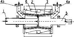
Fig. 1 demonstrates one and has the modification that axial paper pulp is carried,
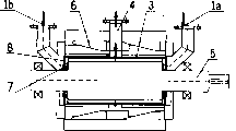
Fig. 2 has the modification that horizontal paper pulp is carried,
Fig. 3 is the modification that is similar to Fig. 2 with bell-shaped rotor,
Fig. 4 is another modification with bell-shaped rotor,
Fig. 5 is the modification with cylindrical shape birotor and axial paper pulp conveying,
Fig. 6 and 7 is for having the double cone shape rotor that narrows down and broaden and the axial paper pulp modification of carrying,
Fig. 8 is the modification with cylindrical shape birotor and horizontal paper pulp conveying,
Fig. 9 has the two-spool modification that axial paper pulp is carried and comprised cylindrical shape and bell-shaped rotor,
Figure 10, Figure 11, Figure 12, Figure 13 have changed the order of cylindrical shape and conical attritioning gap on a rotor, and
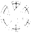
The cutaway view that Figure 14 cuts open for the hatching A-A in Fig. 5.
The specific embodiment
Fig. 1 demonstrates according to a kind of second reduction machine of the present invention, has inlet 1, paper pulp transfer passage 7, attritioning zone 3, outlet 4, rotor 5 and stator 6.Here paper pulp passes the inlet 1 that is located in rotor 5 axis at the center and flows to second reduction machine.In the acceleration region 7 between rotor 5 and shell 6,, cause pressure accumulated like this because sidewall friction or special internals (referring to Figure 14) paper pulp are quickened along circumferencial direction.This paper pulp flows through attritioning zone 3 subsequently and passes outlet 4 and leave described second reduction machine.Shell 6 comprises a ring that can move along axial direction, and a chock 10 has been installed on this ring.The attritioning plate is connected on another chock 11, and attritioning gap 3 is set by shift(ing) ring 9.
Fig. 2 demonstrates the second reduction machine of a similar design, and paper pulp is sent to from the side in this second reduction machine.Paper pulp here pass lateral openings 1 flow in the second reduction machine and by disk 8 towards direction of principal axis deflection.Here since the cause of sidewall friction or specific internals it be accelerated and enter into paper pulp transfer passage 7 between disk 8 and the rotor 5, here passage 7 is as acceleration region.In this acceleration region, paper pulp is quickened further along circumferencial direction, produces the pressure accumulated of necessity like this.Here pressure accumulated 1.5 to 2 the crust scopes in.This pulp flow is passed attritioning zone 3 and is passed the outlet 4 that is located at inlet 1 reverse side place and leave this second reduction machine subsequently.Here, attritioning gap 3 also is to set by adjustable chock 10 and 11.
Fig. 3 and Fig. 4 demonstrate the second reduction machine that is similar to Fig. 2, and it has identical paper pulp carries, but Fig. 3 comprises a taper second reduction machine with the taper of broadening, the taper second reduction machine that Fig. 4 shows the second reduction machine of a taper or narrows down gradually.
Fig. 5 demonstrates the birotor second reduction machine and how to work.In the design shown here, pulp flow is passed the inlet 1 that forms a quill shaft and is passed rotor 5 and arrives the paper pulp transfer passage 2 that is positioned at the center.Since paper pulp inlet 1 quill shaft and in paper pulp transfer passage 2 along the cause of the acceleration of circumferencial direction, so pressure here just accumulation get up.Paper pulp outwards flows and passes the attritioning zone and pass two outlet 4a respectively and 4b leaves second reduction machine subsequently.Adopt 9 pairs of attritioning gaps 23 of an axial adjustable ring to regulate here.Except by chock 10 and this device that a corresponding component 11 that links to each other with the attritioning plate is formed of acting on the whole length, this specification also demonstrates a chock 10 that is divided into chock 10a and 10b.The surface of corresponding component 11 has corresponding chock shape.This makes that energy can better more uniform distribution.
Fig. 6 and 7 demonstrates and is similar to the diconical second reduction machine of having of Fig. 5, and wherein when seeing from paper pulp transfer passage 2, the conical in shape in Fig. 6 broadens towards outlet 4a and 4b respectively, and narrows down in Fig. 7.
The function of this second reduction machine is the same with the double cylinder-shaped second reduction machine shown in Fig. 5.
Demonstrate another possible embodiment in Fig. 8, wherein here paper pulp passes inlet 1a and 1b towards axle respectively and is sent on both sides, and is deflected paper feed slurry transfer passage 7 by disk 8.Paper pulp enters the attritioning gap 3 on the both sides and passes outlet 4 at the center and is discharged from therefrom.Same paper pulp path also can adopt a kind of biconial to realize, this biconial can be designed as from the taper that broadens and live and narrow down of central outlet of outside inlet.
Is example to have birotor with the axial entrance 1 that is designed to quill shaft, and Fig. 9 demonstrates a kind of combination in cylindrical shape and conical attritioning zone.Except shown in distortion, paper pulp can be on both sides flow by inlet, and by the deflection of disk institute, outlet can be positioned at the center.
Figure 10-13 demonstrates a kind of combination in an epitrochanterian cylindrical shape and conical attritioning zone.In the case, the paper pulp pipe (Figure 11, Figure 12) of can also flowing through, the conic section of perhaps can at first flowing through (Figure 10, Figure 13), this taper shape can have a shape that broadens (Figure 10, Figure 12), perhaps have a shape that narrows down (Figure 11, Figure 13).Conical broaden or narrow down determined by the flow direction of paper pulp.
Figure 14 demonstrates the cutaway view of cutting open according to A-A line among Fig. 5.Can see the internals 12 that is referred to as blade or blade here.These internals 12 paper pulp transfer passage 2 be divided into a plurality of independent paper pulp transfer passages 2 ', by these passages, pulp suspension by guided to from the charging aperture that is arranged on the center outside on attritioning gap 3.Be made into the internals (12) of the chock of a filling by these, this pulp suspension is quickened extraly and has been increased pressure.Yet, these internals also can be hollow or be round on the surface, for example be made into blade.Such internals also can be used in the paper pulp transport channel 7 of for example Fig. 1-4 or 8,10-13, can also be used among Fig. 6,7 or 9 of the modification that is similar to Fig. 5.
Claims (10)
1. second reduction machine, comprise a rotor and a stator, and have an inlet duct and a cylindrical shape or the conical attritioning gap between rotor and stator, it is characterized in that, paper pulp transfer passage (2,7) (1) extends upwardly to attritioning gap (3) along radial direction from inlet duct, between inlet duct (1) and attritioning gap (3), be provided with a disk (8), this disk (8) has the inlet surface and the exit surface to circumferential extension of relative configuration, wherein the inlet surface of disk (8) is the paper pulp stream rotor that radially inwardly leads, and the exit surface of disk (8) radially outward leads paper pulp stream around the attritioning gap (3) of the whole circumference of disk.
2. second reduction machine according to claim 1 is characterized in that, paper pulp transfer passage (2,7) is a kind of rotational symmetric design.
3. second reduction machine according to claim 1 is characterized in that, the inlet duct (1) that links to each other with paper pulp transfer passage (2) is positioned on the axis consistent with the axis of rotor.
4. according to each described second reduction machine in the claim 1 to 3, it is characterized in that, be provided with a kind of cylindrical rotor (5).
5. according to each described second reduction machine in the claim 1 to 3, it is characterized in that, be provided with a kind of bell-shaped rotor that broadens along the pulp flow direction (5).
6. according to each described second reduction machine in the claim 1 to 3, it is characterized in that, be provided with a kind of bell-shaped rotor that narrows down along the pulp flow direction (5).
7. according to each described second reduction machine in the claim 1 to 3, it is characterized in that, be provided with a kind of birotor (5).
8. second reduction machine according to claim 7 is characterized in that, paper pulp transfer passage (2) is positioned between two rotors (5).
9. second reduction machine according to claim 7 is characterized in that, series connection is provided with a cylindrical shape and a conical attritioning gap (3).
10. second reduction machine according to claim 1 is characterized in that, internals (12) especially blade is installed in the paper pulp transfer passage (2,7) and/or inlet duct (1).
Applications Claiming Priority (2)
| Application Number | Priority Date | Filing Date | Title |
|---|---|---|---|
| ATA168/2000 | 2000-02-03 | ||
| AT0016800A AT408769B (en) | 2000-02-03 | 2000-02-03 | REFINER |
Publications (2)
| Publication Number | Publication Date |
|---|---|
| CN1311370A CN1311370A (en) | 2001-09-05 |
| CN1201048C true CN1201048C (en) | 2005-05-11 |
Family
ID=3654399
Family Applications (1)
| Application Number | Title | Priority Date | Filing Date |
|---|---|---|---|
| CNB011119225A Expired - Lifetime CN1201048C (en) | 2000-02-03 | 2001-02-02 | Refining machine |
Country Status (8)
| Country | Link |
|---|---|
| US (1) | US6637686B2 (en) |
| EP (1) | EP1122356B1 (en) |
| CN (1) | CN1201048C (en) |
| AT (2) | AT408769B (en) |
| BR (1) | BR0100357A (en) |
| CA (1) | CA2333799A1 (en) |
| DE (1) | DE50107162D1 (en) |
| ES (1) | ES2246939T3 (en) |
Cited By (1)
| Publication number | Priority date | Publication date | Assignee | Title |
|---|---|---|---|---|
| CN108348919A (en) * | 2015-11-04 | 2018-07-31 | 耐驰精细研磨技术有限公司 | Grinding device and method for comminuted starting materials |
Families Citing this family (10)
| Publication number | Priority date | Publication date | Assignee | Title |
|---|---|---|---|---|
| DE102005013693A1 (en) | 2005-03-21 | 2006-09-28 | Cvp Clean Value Plastics Gmbh | Process and plant for producing a pulp from agglomerated mixed plastic |
| SE530009C2 (en) * | 2006-06-01 | 2008-02-05 | Metso Paper Inc | Apparatus for the alignment of a grinder's shaft device |
| FI121963B (en) * | 2009-07-03 | 2011-06-30 | Metso Paper Inc | refiner |
| CN103061189B (en) * | 2013-01-16 | 2015-01-07 | 苏州飞宇精密科技股份有限公司 | Cylindrical pulping machine with double pulping areas |
| CN103061190B (en) * | 2013-01-16 | 2015-01-07 | 苏州飞宇精密科技股份有限公司 | Cylindrical single-grinding grinder |
| CN103362013A (en) * | 2013-04-03 | 2013-10-23 | 上海尚鼎机械科技有限公司 | Gap adjustment optimizing structure of cylindrical refiner |
| CN104480767B (en) * | 2014-11-10 | 2016-11-09 | 合肥宏图彩印有限公司 | A kind of hold-down mechanism in cylinder fiberizer |
| CN104452400B (en) * | 2014-11-10 | 2016-11-09 | 合肥宏图彩印有限公司 | A kind of hold-down mechanism for lava flybar |
| CN105908554B (en) * | 2015-08-26 | 2019-01-18 | 李军 | Column type defibering fiberizer |
| CN113058681B (en) * | 2021-04-16 | 2022-09-30 | 哈尔滨工程北米科技有限公司 | Germ-remaining rice processing method |
Family Cites Families (15)
| Publication number | Priority date | Publication date | Assignee | Title |
|---|---|---|---|---|
| FR1158726A (en) * | 1956-10-18 | 1958-06-18 | Dorries A G O | Refining machine for pulp and similar applications |
| US3586250A (en) * | 1968-10-30 | 1971-06-22 | Bauer Bros Co | Adjustable noncoaxial disc refiner |
| US3708130A (en) * | 1971-03-09 | 1973-01-02 | Norton Co | Pulp refiners |
| US3806050A (en) * | 1971-05-12 | 1974-04-23 | E Cumpston | Mixer-refiner |
| GB1407712A (en) * | 1973-03-09 | 1975-09-24 | Cumpston Edward H | Mixer-refiner |
| FI59272C (en) * | 1980-03-25 | 1981-07-10 | Enso Gutzeit Oy | SKIVRAFFINOER |
| US4401280A (en) * | 1980-09-08 | 1983-08-30 | Sunds Defibrator, Inc. | Disc-type pulp refining apparatus |
| SE456748B (en) * | 1986-04-10 | 1988-10-31 | Kamyr Ab | PROCEDURE AND DEVICE FOR REFINING FIBER MATERIAL |
| AT389532B (en) * | 1987-11-05 | 1989-12-27 | Andritz Ag Maschf | REFINER FOR CRUSHING OR FOR GRINDING, IN PARTICULAR, WET OR FIBER MATERIAL MIXED WITH WATER |
| US4986480A (en) * | 1989-06-29 | 1991-01-22 | Kamyr Ab | Method and apparatus for feeding a conical refiner |
| FI85391C (en) * | 1989-10-05 | 1992-04-10 | Sunds Defibrator Jylha Oy | Konraffinör |
| AT394588B (en) * | 1990-01-23 | 1992-05-11 | Andritz Ag Maschf | SHREDDING AREA SEGMENT FOR DRUM REFINER AND HIGHLY ARRANGED ARRANGEMENT |
| US5383608A (en) * | 1993-03-22 | 1995-01-24 | Andritz Sprout-Bauer, Inc. | Twin conical refiner with dual ribbon feeders |
| US5813618A (en) * | 1995-11-28 | 1998-09-29 | Andritz Sprout-Bauer, Inc. | Continuous cyclindrical wood pulp refiner |
| AT408768B (en) * | 2000-02-03 | 2002-03-25 | Andritz Ag Maschf | REFINER FOR MILLING FIBER FIBERS |
-
2000
- 2000-02-03 AT AT0016800A patent/AT408769B/en not_active IP Right Cessation
-
2001
- 2001-01-25 DE DE50107162T patent/DE50107162D1/en not_active Expired - Lifetime
- 2001-01-25 ES ES01101560T patent/ES2246939T3/en not_active Expired - Lifetime
- 2001-01-25 EP EP01101560A patent/EP1122356B1/en not_active Expired - Lifetime
- 2001-01-25 AT AT01101560T patent/ATE302874T1/en not_active IP Right Cessation
- 2001-02-01 CA CA002333799A patent/CA2333799A1/en not_active Abandoned
- 2001-02-02 CN CNB011119225A patent/CN1201048C/en not_active Expired - Lifetime
- 2001-02-02 US US09/775,996 patent/US6637686B2/en not_active Expired - Fee Related
- 2001-02-05 BR BR0100357-7A patent/BR0100357A/en not_active IP Right Cessation
Cited By (1)
| Publication number | Priority date | Publication date | Assignee | Title |
|---|---|---|---|---|
| CN108348919A (en) * | 2015-11-04 | 2018-07-31 | 耐驰精细研磨技术有限公司 | Grinding device and method for comminuted starting materials |
Also Published As
| Publication number | Publication date |
|---|---|
| BR0100357A (en) | 2001-10-02 |
| ATA1682000A (en) | 2001-07-15 |
| CA2333799A1 (en) | 2001-08-03 |
| CN1311370A (en) | 2001-09-05 |
| EP1122356B1 (en) | 2005-08-24 |
| DE50107162D1 (en) | 2005-09-29 |
| ES2246939T3 (en) | 2006-03-01 |
| EP1122356A2 (en) | 2001-08-08 |
| ATE302874T1 (en) | 2005-09-15 |
| US6637686B2 (en) | 2003-10-28 |
| AT408769B (en) | 2002-03-25 |
| US20010020660A1 (en) | 2001-09-13 |
| EP1122356A3 (en) | 2001-11-28 |
Similar Documents
| Publication | Publication Date | Title |
|---|---|---|
| CN1201048C (en) | Refining machine | |
| CN1021297C (en) | Centrifugal separator | |
| US4042172A (en) | Bowl centrifuge rotor | |
| US10792665B2 (en) | Agitator ball mill | |
| CN1016320B (en) | Centrifugal separator | |
| US20080015099A1 (en) | Separator Comprising a Spinning Drum with a Disc Stack | |
| US10532365B2 (en) | Centrifugal separator having an outlet opening opposite a stack of separation disks | |
| US9475068B2 (en) | Smoothly accelerating channel inlet for centrifugal separator | |
| EP1539354A1 (en) | A refining surface for a refiner for defibering material containing lignocellulose | |
| CN104955580A (en) | A centrifugal separator | |
| WO1997013027A1 (en) | Cleaner with inverted hydrocyclone | |
| CN1056787C (en) | Method and device for separation of a fine grained solid matter into two particle fractions | |
| CN1184375C (en) | Refining machine | |
| CN113518665B (en) | Millstone segment with feed recess | |
| EP2628544A1 (en) | Centrifugal separator with inlet arrangement | |
| US20040033130A1 (en) | Compound friction vacuum pump | |
| US20020139723A1 (en) | Pressure screen to remove impurities from a paper fiber suspension containing impurities and its use | |
| EP1833610B1 (en) | Method and device for processing pulp | |
| US20070029231A1 (en) | Apparatus for treating a fibrous suspension | |
| CN1542220A (en) | Screen for cleaning a fiber suspension | |
| SE511786C2 (en) | Screening device with two screening chambers for separating fiber suspensions | |
| US20110253327A1 (en) | Method for refining cellulose fibers in aqueous suspension as well as refiner filling to implement said method | |
| CN218784899U (en) | Distributor for disc separator | |
| MXPA01001293A (en) | Screen. | |
| WO2000052260A1 (en) | Screening apparatus |
Legal Events
| Date | Code | Title | Description |
|---|---|---|---|
| C06 | Publication | ||
| PB01 | Publication | ||
| C14 | Grant of patent or utility model | ||
| GR01 | Patent grant | ||
| CX01 | Expiry of patent term |
Granted publication date: 20050511 |
|
| CX01 | Expiry of patent term |