CN1197175C - White light emitting phosphor blend for LCD devices - Google Patents
White light emitting phosphor blend for LCD devices Download PDFInfo
- Publication number
- CN1197175C CN1197175C CNB018020682A CN01802068A CN1197175C CN 1197175 C CN1197175 C CN 1197175C CN B018020682 A CNB018020682 A CN B018020682A CN 01802068 A CN01802068 A CN 01802068A CN 1197175 C CN1197175 C CN 1197175C
- Authority
- CN
- China
- Prior art keywords
- fluorescent material
- light
- fluorescent
- radiation source
- emission wavelength
- Prior art date
- Legal status (The legal status is an assumption and is not a legal conclusion. Google has not performed a legal analysis and makes no representation as to the accuracy of the status listed.)
- Expired - Fee Related
Links
Images
Classifications
-
- H—ELECTRICITY
- H01—ELECTRIC ELEMENTS
- H01L—SEMICONDUCTOR DEVICES NOT COVERED BY CLASS H10
- H01L33/00—Semiconductor devices with at least one potential-jump barrier or surface barrier specially adapted for light emission; Processes or apparatus specially adapted for the manufacture or treatment thereof or of parts thereof; Details thereof
- H01L33/48—Semiconductor devices with at least one potential-jump barrier or surface barrier specially adapted for light emission; Processes or apparatus specially adapted for the manufacture or treatment thereof or of parts thereof; Details thereof characterised by the semiconductor body packages
- H01L33/50—Wavelength conversion elements
- H01L33/501—Wavelength conversion elements characterised by the materials, e.g. binder
- H01L33/502—Wavelength conversion materials
- H01L33/504—Elements with two or more wavelength conversion materials
-
- C—CHEMISTRY; METALLURGY
- C09—DYES; PAINTS; POLISHES; NATURAL RESINS; ADHESIVES; COMPOSITIONS NOT OTHERWISE PROVIDED FOR; APPLICATIONS OF MATERIALS NOT OTHERWISE PROVIDED FOR
- C09K—MATERIALS FOR MISCELLANEOUS APPLICATIONS, NOT PROVIDED FOR ELSEWHERE
- C09K11/00—Luminescent, e.g. electroluminescent, chemiluminescent materials
- C09K11/08—Luminescent, e.g. electroluminescent, chemiluminescent materials containing inorganic luminescent materials
- C09K11/77—Luminescent, e.g. electroluminescent, chemiluminescent materials containing inorganic luminescent materials containing rare earth metals
- C09K11/7728—Luminescent, e.g. electroluminescent, chemiluminescent materials containing inorganic luminescent materials containing rare earth metals containing europium
- C09K11/7734—Aluminates
-
- C—CHEMISTRY; METALLURGY
- C09—DYES; PAINTS; POLISHES; NATURAL RESINS; ADHESIVES; COMPOSITIONS NOT OTHERWISE PROVIDED FOR; APPLICATIONS OF MATERIALS NOT OTHERWISE PROVIDED FOR
- C09K—MATERIALS FOR MISCELLANEOUS APPLICATIONS, NOT PROVIDED FOR ELSEWHERE
- C09K11/00—Luminescent, e.g. electroluminescent, chemiluminescent materials
- C09K11/08—Luminescent, e.g. electroluminescent, chemiluminescent materials containing inorganic luminescent materials
- C09K11/77—Luminescent, e.g. electroluminescent, chemiluminescent materials containing inorganic luminescent materials containing rare earth metals
- C09K11/7728—Luminescent, e.g. electroluminescent, chemiluminescent materials containing inorganic luminescent materials containing rare earth metals containing europium
- C09K11/7737—Phosphates
- C09K11/7738—Phosphates with alkaline earth metals
-
- H—ELECTRICITY
- H05—ELECTRIC TECHNIQUES NOT OTHERWISE PROVIDED FOR
- H05B—ELECTRIC HEATING; ELECTRIC LIGHT SOURCES NOT OTHERWISE PROVIDED FOR; CIRCUIT ARRANGEMENTS FOR ELECTRIC LIGHT SOURCES, IN GENERAL
- H05B33/00—Electroluminescent light sources
- H05B33/12—Light sources with substantially two-dimensional radiating surfaces
- H05B33/14—Light sources with substantially two-dimensional radiating surfaces characterised by the chemical or physical composition or the arrangement of the electroluminescent material, or by the simultaneous addition of the electroluminescent material in or onto the light source
-
- H—ELECTRICITY
- H01—ELECTRIC ELEMENTS
- H01L—SEMICONDUCTOR DEVICES NOT COVERED BY CLASS H10
- H01L2924/00—Indexing scheme for arrangements or methods for connecting or disconnecting semiconductor or solid-state bodies as covered by H01L24/00
- H01L2924/0001—Technical content checked by a classifier
- H01L2924/0002—Not covered by any one of groups H01L24/00, H01L24/00 and H01L2224/00
-
- H—ELECTRICITY
- H10—SEMICONDUCTOR DEVICES; ELECTRIC SOLID-STATE DEVICES NOT OTHERWISE PROVIDED FOR
- H10K—ORGANIC ELECTRIC SOLID-STATE DEVICES
- H10K50/00—Organic light-emitting devices
- H10K50/10—OLEDs or polymer light-emitting diodes [PLED]
- H10K50/11—OLEDs or polymer light-emitting diodes [PLED] characterised by the electroluminescent [EL] layers
- H10K50/125—OLEDs or polymer light-emitting diodes [PLED] characterised by the electroluminescent [EL] layers specially adapted for multicolour light emission, e.g. for emitting white light
-
- Y—GENERAL TAGGING OF NEW TECHNOLOGICAL DEVELOPMENTS; GENERAL TAGGING OF CROSS-SECTIONAL TECHNOLOGIES SPANNING OVER SEVERAL SECTIONS OF THE IPC; TECHNICAL SUBJECTS COVERED BY FORMER USPC CROSS-REFERENCE ART COLLECTIONS [XRACs] AND DIGESTS
- Y02—TECHNOLOGIES OR APPLICATIONS FOR MITIGATION OR ADAPTATION AGAINST CLIMATE CHANGE
- Y02B—CLIMATE CHANGE MITIGATION TECHNOLOGIES RELATED TO BUILDINGS, e.g. HOUSING, HOUSE APPLIANCES OR RELATED END-USER APPLICATIONS
- Y02B20/00—Energy efficient lighting technologies, e.g. halogen lamps or gas discharge lamps
Abstract
There is provided a white light illumination system including a radiation source, a first luminescent material having a peak emission wavelength of about 570 to about 620 nm, and a second luminescent material having a peak emission wavelength of about 480 to about 500 nm, which is different from the first luminescent material. The LED may be a UV LED and the luminescent materials may be a blend of two phosphors. The first phosphor may be an orange emitting Eu<2+>, Mn<2+> doped strontium pyrophosphate, (Sr0.8Eu0.1Mn0.1)2P2O7. The second phosphor may be a blue-green emitting Eu<2+> doped SAE, (Sr0.90-0.99 Eu0.01-0.1)4Al14O25. A human observer perceives the combination of the orange and the blue-green phosphor emissions as white light.
Description
Technical field
The present invention relates generally to a kind of white lumination system, especially relate to a kind of ceramic fluorescent material blend that is used for the UV ray of light-emitting diode (" LED ") emission is converted into white light.
Background technology
White light emission LED is used as the back illumination of liquid crystal display, also is used to replace small-sized conventional lamp and fluorescent lamp.Show as people such as S.Nakamura, 216-221 page or leaf (Springer in " blue laser diode " that is hereby incorporated by, 1997), 10.4 chapters are discussed, and white light LEDs is to form a kind of ceramic fluorescent material layer by the output surface at blue light emitting semiconductor LED to make.Traditionally, blue led is a kind of InGaN single quantum well LED, and fluorescent material is the yttrium aluminium garnet (" YAG:Ce ") of mixing cerium, Y
3Al
5O1
2: Ce
3+The blue-light excited fluorescent material of LED emission makes its emission gold-tinted.The yellow light mix that the blue light transmission of LED emission is crossed fluorescent material and launched with fluorescent material.The blue light that the observer feels is white light with mixing of gold-tinted.
But blue led-YAG:Ce fluorescent material white lumination system has following shortcoming.Led color output (as the distribute power and the peak emission wavelength of spectrum) is with the band gap width and the variable power that puts on LED of LED active coating.In process of production, to be made into the actual band gap width of its active coating bigger or little than what wish to get for a certain proportion of LED.Thereby the color output of such LED will depart from wishes to get parameter.And even the band gap of specific LED has the width of wishing to get, the power that puts on this LED in the LED course of work can depart from the value of wishing to get usually.This also can cause the color output of LED to depart from and wish to get parameter.Since the light of system's emission comprises the blue light ingredient from LED, if departing from, the output of the color of LED wishes to get parameter, then the light of system is exported also will depart from and is wished to get parameter.And wish to get the color output that can cause system that departs from excessive between parameter and present non-white light (i.e. blue the or band yellow of band).
And, in LED lamp production process, the output of the color of blue led-YAG:Ce fluorescent material system since frequent, inevitable, conventional departing from wish to get parameter (i.e. the system deviation of Sheng Chaning) change very big because the color of blue led-YAG:Ce fluorescent material system is exported the unusual sensitivity of the thickness of fluorescent material.If fluorescent material is too thin, the blue light that then has more than the LED emission of wishing to get quantity penetrates fluorescent material, and the output of the light of the LED-fluorescent material system of combination will to present band blue because blue led output is preponderated.On the contrary, if fluorescent material is too thick, then is less than the blue LED light of wishing to get quantity and penetrates thick YAG:Ce fluorescent material layer.So it is yellow that the LED-fluorescent material system of combination will present band, because the output of the yellow of YAG:Ce fluorescent material is preponderated.
So the thickness of fluorescent material is key variables that affect the color output of prior art systems.Unfortunately, when large-scale production blue led-YAG:Ce fluorescent material system, the precise thickness of control fluorescent material is difficult.The variation of fluorescent material thickness often causes the output of system to be not suitable for white-light illuminating and uses, and makes the color output of system present non-white (promptly band blueness or band are yellow), and this will cause unacceptable blue led-low excessively rate of finished products of YAG:Ce fluorescent material system.
Blue led-YAG:Ce fluorescent material system also can be influenced owing to the halo effect that separately causes of blue and gold-tinted.LED is with some oriented approach emission blue lights.But fluorescent material is (promptly to all directions) emission gold-tinted isotropically.So when the light output of direct-view system (over against the direction of LED emission), light presents band indigo plant-white.On the contrary, when observing light output with some angles, light presents the band yellow because the yellow fluorescent material emission is preponderated.When the output of the light of such system is directed on the plane surface, will be rendered as to be with the yellow ring of light around the band blue region.The present invention is intended to overcome or reduces the problems referred to above at least.
Summary of the invention
According to an aspect of the present invention, a kind of white lumination system is provided, it comprises a radiation source, it has about 570 to the peak emission wavelength of about 620nm a kind of first luminescent material, it has the peak emission wavelength that is different from first luminescent material with a kind of second luminescent material, is about 480 to about 500nm.
According to a further aspect in the invention, provide a kind of white lumination system, it comprises that a peak emission wavelength is the light-emitting diode between 370 to 405nm, a kind of first fluorescent material APO:Eu
2+, Mn
2+, wherein A comprises among Sr, Ca, Ba or the Mg at least a and from following at least a second fluorescent material of selecting:
A) A
4D
14O
25: Eu
2+, wherein A comprises among Sr, Ca, Ba or the Mg at least aly, and D comprises among Al or the Ga at least a;
B) (2AO*0.84P
2O
5* 0.16B
2O
3): Eu
2+, wherein A comprises among Sr, Ca, Ba or the Mg at least a;
C) AD
8O
13: Eu
2+, wherein A comprises among Sr, Ca, Ba or the Mg at least aly, and D comprises among Al or the Ga at least a;
D) A
10(PO
4)
6Cl
2: Eu
2+, wherein A comprises among Sr, Ca, Ba or the Mg at least a; Or
E) A
2Si
3O
8* 2ACl
2: Eu
2+, wherein A comprises among Sr, Ca, Ba or the Mg at least a.
According to a further aspect in the invention, a kind of method of making white lumination system is provided, it comprises has peak emission wavelength for about 480 to about 500nm second fluorescent material to mix the mixture that form a kind of fluorescent material for about 570 to about 620nm first fluorescent material with having to launch having peak emission wavelength, and phosphor mixture is put into the white lumination system adjacent with radiation source.
Description of drawings
Fig. 1 is the schematic diagram of white lumination system according to an embodiment of the invention.
Fig. 2-the 4th, first preferred embodiment according to the present invention, the generalized section of the illuminator of use LED.
Fig. 5 is second preferred embodiment according to the present invention, uses the generalized section of the illuminator of fluorescent lamp.
Fig. 6 is the 3rd preferred embodiment according to the present invention, uses the generalized section of the illuminator of plasma demonstration.
Embodiment
In view of the problems of the prior art, desirable is to obtain a kind of white lumination system, its color output is more insensitive for the variation during system works and production process, as the variation owing to LED power, LED active coating band gap width and luminescent material thickness.Present inventors have been found that if the color of system output do not comprise a large amount of by radiation source, as LED, the visual ray of emission, then the output of the color of this radiation source-luminescent material system will be more insensitive to these variations.In this case, great changes have taken place with LED power, band gap width and luminescent material thickness for the output of the color of system.This term of luminescent material comprises with the powder type (fluorescent material) of in bulk or packing with the luminescent material of solid crystals form (scintillator).
If the white light of system emission lacks by radiation source, as LED, any significantly visible composition of emission, then the output of the color of system will be not have significant change with the thickness of luminescent material.So the LED radiation transmission is crossed the quantity of luminescent material such as fluorescent material, do not influence the color output of system.This can be by dual mode realization at least.
A kind of mode of avoiding influencing system colors output is by using with the sightless wavelength ray radiation emitted of a human eye source.For example, can make up a kind of LED, it is 380nm or littler ultraviolet (UV) ray that emission has the complete sightless wavelength of human eye.And human eye is that UV ray between 380 to 400nm and wavelength are that purple light between 400 to 420nm is more insensitive to wavelength.So, no matter whether fluorescent material is crossed in transmission to the LED ray of emission, has wavelength and is 420nm or the littler ray by the LED emission will not influence the color output of LED-fluorescent material system substantially, because have the about 420nm of wavelength or littler ray is not too visible to human eye.
Second kind of mode of avoiding influencing system colors output is the thick luminescent material that does not allow the ray from radiation source to pass by using.For example, if the visible light between LED emission 420 to 650nm, then in order to guarantee that fluorescent material thickness does not influence the color output of system, fluorescent material should be enough thick with prevent any in a large number penetrate fluorescent material by the LED visible light emitted.But,, be not preferred, because it has reduced the delivery efficiency of system though this mode of avoiding influencing system colors output is possible.
In the above two kinds of cases, only depend on the type of used luminescent material by the color of system's visible light emitted.So in order to make LED-fluorescent material system emission white light, fluorescent material should be launched white light when being subjected to the LED radiation exposure.
Family of the present invention has been found that, when use together have peak emission wavelength between for about 570 to about 620nm the first orange smooth emission luminescent material and when having peak emission wavelength for about 480 the second blue green light emission luminescent materials between about 500nm, the observer feels that their combined transmit is a white light.Any luminescent material, for example having peak emission wavelength is between 570 to 620nm and the fluorescent material between 480 to 500nm, all can be used in combination to form white lumination system with radiation source.Preferably, luminescent material has high-quantum efficiency in the specific emission wavelength of radiation source.And, each luminescent material is preferably transparent to other luminescent material visible light emitted wavelength.
Fig. 1 schematically illustrates above-mentioned principle.Among Fig. 1, radiation source 1 as a LED, is launched ray 2, incides two kinds of luminescent materials, as first fluorescent material 3 and second fluorescent material 4.Two kinds of fluorescent materials 3,4 by the diagonal of illustrating among Fig. 1 separately can mix to show two kinds of fluorescent materials, or two kinds of fluorescent materials can comprise discrete superimposed layer.Diagonal only is used for purpose clearly, is not used in to show boundary line, diagonal angle necessary between fluorescent material.
Ray 2 can have human eye to its insensitive wavelength, as 420nm or lower.Alternatively, fluorescent material 3,4 can be blocked up and not be allowed radiation 2 to penetrate the arrival opposite side.After absorbing the ray 2 of incident, it is 570 to 620nm orange light 5 that 3 emissions of first fluorescent material have peak emission wavelength, and 4 emissions of second fluorescent material to have peak emission wavelength be 480 to 500nm blue green light 6.Orange light 5 that observer 7 feels and blue green light 6 be combined as white light 8.Orange light 5 schematically is shown Fig. 1 and blue green light 6 sends from discrete fluorescent material zone, to illustrate the notion that color mixes.But, should think integral fluorescence material 3 emission light 5, and integral fluorescence material 4 emission light 6.Form single mixing fluorescent material layer if first and second fluorescent materials 3,4 mix, then orange light 5 and blue green light 6 all can be launched from the same area.
Radiation source 1 can comprise any can causing from the one 3 and the 24 fluorescent material radiation emitted source.Preferably, radiation source 1 comprises a LED.But perhaps radiation source 1 also comprises a kind of gas, and for example mercury in fluorescent lamp or the high pressure mercury vapour lamp, or a kind of inert gas is as Ne, Ar and/or the Xe in the plasma demonstration.
For example, radiation source 1 can comprise any LED, when the ray 2 of LED emission is directed on the one 3 and the 24 fluorescent material, causes that the one 3 and the 24 fluorescent material launches the ray 8 that observer 7 is presented white.Therefore, LED can comprise one based on any suitable III-V, the semiconductor diode of II-VI or IV-VI semiconductor layer, and have 360 to the 420nm emission wavelength.For example LED can comprise at least a based on GaN, ZnSe or the semi-conductive semiconductor layer of SiC.If desired, LED also can comprise one or more quantum well at active area.Preferably, the LED active area can comprise a p-n junction, and it comprises GaN, AlGaN and/or InGaN semiconductor layer.This p-n junction can be separated by a thin unadulterated InGaN layer or one or more InGaN quantum well.LED can have one 360 emission wavelength to 420nm, is preferably 370 to 405nm, is most preferably 370 to 390nm.But, having emission wavelength and can use with thick fluorescent material greater than the LED of 420nm, its thickness prevents to penetrate fluorescent material from the light of LED.For example LED can have following wavelength: 370,375,380,390 or 405nm.
The radiation source 1 of white lumination system as above-mentioned be semiconductor light-emitting-diode.But radiation source of the present invention is not limited to semiconductor light-emitting-diode.For example, radiation source can comprise a laser diode or an Organic Light Emitting Diode (OLED).Above-mentioned preferred white lumination system comprises a single radiation source 1.But if desired, for the white light or the white light of handle emission and the light combination of different colours that improve emission, system can adopt multi radiation sources.For example, in display unit, the white light emission system can be used in combination with red, green and/or blue LED.
First luminescent material can be any fluorescent material 3, and its response is from the ray 2 of the incident of radiation source 1, and it is visible light between 570 to 620nm that emission has peak emission wavelength.To have peak emission wavelength be LED between 360 to 420nm if radiation source 1 comprises one, and then first fluorescent material 3 preferably includes APO:Eu
2+, Mn
2+, wherein A comprises among Sr, Ca, Ba or the Mg at least a.Most preferably, first fluorescent material 3 comprises the alkali earth metal phosphate fluorescent material that europium and manganese mix, A
2P
2O
7: Eu
2+, Mn
2+, it can write (A
1-x-yEu
xMn
y)
2P
2O
7, wherein A comprise among Sr, Ca, Ba, the Mg at least a, 0<x≤0.2, and 0<y≤0.2.Preferably, A comprises strontium.This fluorescent material is preferably used for the LED radiation source, because it is visible light between 575 to 595nm that the emission of this fluorescent material has peak emission wavelength, and because be between 360 to 420nm for having peak wavelength, launch as LED, the incident ray, this fluorescent material has high-effect and high-quantum efficiency.Alternatively, first fluorescent material can comprise A
3P
2O
8: Eu
2+, Mn
2+, wherein A comprises among Sr, Ca, Ba or the Mg at least a.
At Eu
2+And Mn
2+In the alkali earth metal phosphate fluorescent material that mixes, the Eu ion is usually as sensitizer, and the Mn ion is usually as activator.Therefore, the Eu ionic absorption is given the Mn ion by the projectile energy (being photon) of radiation source emission and the energy delivery that absorbs.The Mn ion is energy activated to excitation state by the transmission that absorbs, and launches wide radiation zone, and it has the treatment conditions of depending on from about 575 to the 590nm peak wavelengths that change.
Second luminescent material can be any fluorescent material 4, and its response is from the ray 2 of the incident of radiation source 1, and it is visible light between 480 to 500nm that emission has peak emission wavelength.To have peak emission wavelength be LED between 360 to 420nm if radiation source 1 comprises one, then second fluorescent material can comprise any from commercial available fluorescent material, it has is peak emission wavelength between 480 to 500nm, and for having the high-effect and quantum efficiency that peak wavelength is the incident ray between 370 to 420nm.For example, following 5 kinds of fluorescent materials meet this standard:
A) A
4D
14O
25: Eu
2+, wherein A comprises among Sr, Ca, Ba or the Mg at least aly, and D comprises among Al or the Ga at least a;
B) (2AO*0.84P
2O
5* 0.16B
2O
3): Eu
2+, wherein A comprises among Sr, Ca, Ba or the Mg at least a;
C) AD
8O
13: Eu
2+, wherein A comprises among Sr, Ca, Ba or the Mg at least aly, and D comprises among Al or the Ga at least a;
D) A
10(PO
4)
6Cl
2: Eu
2+, wherein A comprises among Sr, Ca, Ba or the Mg at least a; Or
E) A
2Si
3O
8* 2ACl
2: Eu
2+, wherein A comprises among Sr, Ca, Ba or the Mg at least a.
To above-mentioned 5 kinds of fluorescent materials, preferably, be from commercial available composition:
A) Sr
4Al
14O
25: Eu
2+, (just known SAE fluorescent material);
b)(2SrO*0.84P
2O
5*0.16B
2O
3):?Eu
2+;
c)BaAl
8O
13:Eu
2+;
D) (Sr, Mg, Ca)
10(PO
4)
6Cl
2: Eu
2+Or
e)Sr
2Si
3O
8*2SrCl
2:Eu
2+。
These have the fluorescent material of peak emission wavelength scope from 480 to 493nm edits at S.Shionoya and W.M.Yen, and CRC publishing house (1987,1999) " states in the fluorescent material handbook one book 389-432 page or leaf, is hereby incorporated by.So second fluorescent material 4 can comprise with one or more fluorescent materials a) to e) combination in any.The SAE fluorescent material is preferred, is because it is that 340 to 400nm incident ray has at least 90% quantum efficiency to having wavelength, and have visible light seldom or do not have an absorption of selection.
But other has peak emission wavelength is between 570 to 620nm or the fluorescent material between 480 to 500nm can replace or uses with above-mentioned fluorescent material.For example, for the radiation source except that LED, be that the incident ray of 254nm and 174nm has high-effect and fluorescent material high-quantum efficiency for having peak wavelength, can be respectively applied for fluorescent lamp and plasma display application.In fluorescent lamp, the emission of mercury vapour has the peak emission wavelength of 254nm, and in the Plasma Display, the Xe plasma discharge has the peak emission wavelength of 147nm.
According to a preferred aspect of the present invention, first fluorescent material 3 and second fluorescent material 4 are disperseed.Most preferably, first fluorescent material 3 and second fluorescent material 4 mix and form uniform blend.The amount of each fluorescent material depends on the kind of used fluorescent material and the kind of radiation source in the blend.But, the 1 and the mixing of the 24 fluorescent material should make and present white from the emission 5 of first fluorescent material 3 with from 8 couples of observers 7 of combination of the emission 6 of second fluorescent material 4.
Alternatively, first and second fluorescent materials 3,4 can comprise the discrete layer that is formed at radiation source 1 top.But, the ray substantially transparent that fluorescent material is launched under the last fluorescent material layer reply.And one of two kinds of fluorescent materials 3,4 can comprise the discrete particle that embeds another fluorescent material layer.If desired, a kind of in the one 3 and the 24 fluorescent material or both can be substituted by a kind of single crystal scintillator together, and it has between 570 to 620nm and/or the peak emission wavelength between 480 to 500nm.
First preferred embodiment according to the present invention, first and second fluorescent material are placed in the white lumination system that comprises the LED radiation source.The white lumination system of preferred aspect can have various structure according to the present invention.
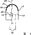
First preferred structure schematically illustrates at Fig. 2.Illuminator comprises a light-emitting diode chip for backlight unit 11 and the electric lead-in wire 13 that is attached on the led chip.Lead-in wire 13 can comprise the thin wires that supported by thicker lead frame 15, or lead-in wire can comprise the self-supporting electrode, and then lead frame can omit.Lead-in wire 13 provides electric current for led chip 11, thereby makes led chip 11 divergent-rays.
Led chip 11 is encapsulated in envelope to be had in the housing 17 of led chip and encapsulating material 19.Encapsulating material preferably includes a kind of UV resistance epoxy.Housing 17 can be, for example glass or plastics.Encapsulating material can be, for example epoxy or polymeric material are as silicones.But an independent housing 17 can be omitted, and the outer surface of encapsulating material 19 can comprise housing 17.Led chip 11 can by, for example, lead frame 15, self-supporting electrode, housing 17 bottoms be installed in housing or lead frame on pedestal support.
First preferred structure of illuminator comprises fluorescent material layer 21, and it comprises first fluorescent material 3 and second fluorescent material 4.Fluorescent material layer 21 can be by applying on led chip 11 and dryly a kind ofly contain the one 3 and the suspended substance of the 24 fluorescent material, and be formed at the light-emitting area top of led chip 11 or directly be formed on the light-emitting area.After the drying, fluorescent material 3,4 forms a solid state fluorescent material layer or coating 21.Housing 17 and encapsulating material 19 are all answered transparent in to allow white light 23 transmissions to cross these elements.Fluorescent material emission white light 23, it comprises orange light of being launched by first fluorescent material 35 and the blue green light of being launched by second fluorescent material 46.
Fig. 3 illustrates second preferred structure according to the system of first preferred embodiment of the present invention.Except the one 3 and the 24 fluorescent material is dispersed in the encapsulating material 19, rather than be formed at outside led chip 11 tops, Fig. 3 structure is identical with Fig. 2 structure.The the one 3 and the 24 fluorescent material can be dispersed in the single area of encapsulating material 19 or spread all in the whole volume of encapsulating material.The dispersion of fluorescent material in encapsulating material 19 be by, for example, powder is added in a kind of polymer matrix, then cure polymer parent and solidified polymeric material.Alternatively, fluorescent material can mix the epoxy that enters encapsulation.Other fluorescent material process for dispersing also can use.First fluorescent material 3 and second fluorescent material 4 mix before can joining encapsulating material 19 at the mixture of these powder 3,4 in advance, and perhaps fluorescent material 3,4 joins in the encapsulating material 19 discriminably.Alternatively, if desired, comprise that the solid state fluorescent material layer 21 of first and second fluorescent materials 3,4 can be inserted in the encapsulating material 19.In this structure, the ray 25 that fluorescent material layer 21 absorbs by the LED emission, and launch white light 23 in response.
Fig. 4 illustrates the 3rd preferred structure of the system of first preferred embodiment according to the present invention.Except the fluorescent material layer 21 that contains first and second fluorescent materials 3,4 is formed on the housing 17, rather than be formed at outside led chip 11 tops, the structure of Fig. 4 is identical with Fig. 2's.Fluorescent material layer 21 preferably is formed at the inner surface of housing 17, and but, if desired, fluorescent material layer can be formed at the outer surface of housing.Fluorescent material layer 21 can be coated on whole surface of shell or only apply the top on housing 17 surfaces.
Certainly, the embodiment of Fig. 2-4 can combine, and fluorescent material can be positioned at any two or all three positions or any one other suitable positions, for example separates with housing or the integrated LED of advancing.
According to second preferred embodiment of the present invention, first and second fluorescent material 3,4 are placed into the white lumination system that contains the fluorescent lamp radiation source.The part of fluorescent lamp schematically illustrates in Fig. 5.Lamp 31 is preferably on the inner surface on lampshade surface 33, contains fluorescent material coating 35, and it comprises the one 3 and the 24 fluorescent material.Fluorescent lamp 31 preferably also contains lamp socket 37 and negative electrode 39.Lampshade 33 envelopes have gas, and as mercury, its response puts on the voltage emission UV ray on the negative electrode 39.
According to the third preferred embodiment of the present invention, the one 3 and the 24 fluorescent material is placed into the white lumination system that contains plasma display system.Any plasma display system, for example AC or DC Plasmia indicating panel all can use, and edit CRC publishing house (1987 as S.Shionoya and W.M.Yen, 1999) " device described in the fluorescent material handbook one book 623-639 page or leaf is hereby incorporated by.Fig. 6 schematically illustrates a unit of DC plasm display device 41.This unit contain one first glass plate 42, second glass plate 43, at least a negative electrode 44, at least a anode 45, one comprise the one 3 and the 24 fluorescent materials material layer 46, barrier rib 47 and inert gas space 48.In the AC plasma display system, an extra dielectric layer is added between the negative electrode and the gas compartment 48.Apply the vacuum ultraviolet rays (VUV) that voltage causes the inert gas emission short wavelength in the space 48 at anode 45 and 44 on negative electrode, this rays excite fluorescent material layer 46 makes its emission white light.
Independent fluorescent material 3 and 4 can pass through, for example, and any ceramic powders method such as wet chemistry method or solid state process and make.Preferably, the method for making first fluorescent material 3 of the strontium phosphate fluorescent material that comprises that europium and manganese mix comprises the following step.
At first, initial (starting) compound of first fluorescent material artificially in crucible is mixed or is mixed or mechanically mix or mix in other suitable containers such as ball mill, to form initial powder mixture.Precursor compound can comprise the initial fluorescence compound of any oxide, phosphate, hydroxide, oxalates, carbonate and/or nitrate.Preferred initial fluorescence compound comprises strontium monophosphate SrHPO
4, manganese carbonate MnCO
3, europium oxide Eu
2O
3And phosphoric acid hydrogen ammonia (NH
4) HPO
4Powder.(NH
4) HPO
4Powder preferably is added into the amount of the stoichiometric ratio 2% that comprises every mole of first fluorescent material that surpasses output.If desired, little excessive strontium compound also can be added into.If wish to replace some or all of strontiums with calcium, barium and/or magnesium, calcium, barium and magnesium precursor compound also can be added into.
Initial then mixture of powders heated 1-5 hour in about 300 to 800 ℃ air, was preferably 600 ℃.Then the powder of gained is mixed again, and roasting in about 1000 to 1250 ℃ reducing atmosphere subsequently, be preferably 1000 ℃, to form the fluorescent material body or the piece of calcining.Preferably, initial powder mixture contained under the atmosphere of nitrogen and 0.1-10% hydrogen calcining 4 to 10 hours in stove, be preferably 8 hours, and close stove subsequently and cooling off under same atmosphere.
In order easily fluorescent powder to be coated on certain part of white lumination system, the fluorescent material body of solid-state calcining can change into first fluorescent material 3.This solid state fluorescent material body can utilize any crushing, grind or comminuting method, as wet method grind, dry method grinds, spray to grind or crush and change into first fluorescent material.Preferably, this solid wet method in propyl alcohol, methyl alcohol and/or water grinds, and subsequent drying.
Second fluorescent material 4 can be selected from the one or more combination in any following 5 kinds of fluorescent materials:
A) A
4D
14O
25: Eu
2+, be preferably Sr
4Al
14O
25: Eu
2+(" SAE ");
B) (2AO*0.84P
2O
5* 0.16B
2O
3): Eu
2+, be preferably (2SrO*0.84P
2O
5* 0.16B
2O
3): Eu
2+
C) AD
8O
13: Eu
2+, be preferably BaAl
8O
13: Eu
2+
D) A
10(PO
4)
6Cl
2: Eu
2+, be preferably (Sr, Mg, Ca)
10(PO
4)
6Cl
2: Eu
2+Or
E) A
2Si
3O
8* 2ACl
2: Eu
2+, be preferably Sr
2Si
3O
8* 2SrCl
2: Eu
2+
The method of making these fluorescent materials is being known in the art, and edits as S.Shionoya and W.M.Yen, and CRC publishing house (1987,1999) " described in the fluorescent material handbook one book 389-432 page or leaf, is hereby incorporated by.For example, SAE Preparation of Fluorescent Material method comprises alpha-aluminium oxide, europium oxide and strontium carbonate and borate flux are mixed, at 1200 ℃ of roasting mixture several hrs and subsequently at forming gas (98%N
2/ 2%H
2) middle cooling blend, pulverize also screening calcined body, at 1300 ℃ of wet H
2/ N
2To the powder roasting again of gained, and then pulverize again the roasting body and form second powder 4 under the gas mixture.Preferably the composition of SAE fluorescent material is (Sr
1-xEu
x)
4Al
14O
25, wherein the x scope is 0.1 to 0.01, and has preferred value 0.1.Replace strontium carbonate with brium carbonate, similar methods can be used for forming BaAl
8O
13: Eu
2+Fluorescent material.
For (2SrO*0.84P
2O
5* 0.16B
2O
3): Eu
2+Fluorescent material, original material are SrHPO
4, SrCO
3, Eu
2O
3And H
3BO
3(99.5%).Roasting was carried out several hours in little reducing atmosphere under 1100 to 1250 ℃.Fluorescent material preferably comprises the Eu of 2-3%mol.Be used for (Sr, Mg, Ca)
10(PO
4)
6Cl
2: Eu
2+Fluorescent material, original material are BaHPO
4, BaCO
3, CaCO
3, MgO, NH
4Cl and Eu
2O
3Roasting is carried out in 800 ℃ of air, after pulverizing once more, carries out in little reducing atmosphere.Be used for Sr
2Si
3O
8* 2SrCl
2: Eu
2+Fluorescent material, original material are to have 0.1Eu
2O
3SrCO
3, SiO
2And SrCl
2Fluorescent material with 2: 3: 2 mixed.This original material and water mix, and 850 ℃ of following roastings are 3 hours in air, pulverize roasting and pulverizing once more again in 950 ℃ of little reducing atmospheres.And then the calcined body of pulverizing washes with water to remove remaining SrCl
2But, anyly in 5 kind of second fluorescent material 4 powder all can from commerce, obtain, thereby blanking method is unimportant really to make them.
Then, the one 3 and the 24 fluorescent material is mixed or mixed in together and form a kind of fluorescent material blend or mixture.Powder 3,4 can mix the artificially in crucible, also can mechanically mix in another suitable containers such as ball mill.Certainly, if desired, the fluorescent material blend can comprise the powder more than two kinds.Alternatively, first and second calcined bodies can be pulverized and be mixed.
The fluorescent material blend synthetic can based on the 1 and the combination of the 24 fluorescent material and the peak emission wavelength of radiation source 1 be optimized.For example, be the radiation source of 405nm for peak emission wavelength, the fluorescent material blend preferably contains weight and accounts for 89% (Sr
0.8Eu
0.1Mn
0.1)
2P
2O
7And weight accounts for 11% SAE.On the contrary, be the radiation source of 380nm for peak emission wavelength, the fluorescent material blend preferably contains weight and accounts for 77% (Sr
0.8Eu
0.1Mn
0.1)
2P
2O
7Account for 23% SAE with weight.
Then, the fluorescent material blend is placed in the white lumination system.For example, the fluorescent material blend can be placed on led chip top, is dispersed in the encapsulating material or is coated on the surface of shell, as described in about first preferred embodiment of the present invention.
If the fluorescent material blend is coated on led chip or the housing, then preferably, the suspended substance of fluorescent material blend and liquid is used to apply led chip or surface of shell.Suspended substance also comprises a kind of adhesive alternatively in solvent.Preferably, adhesive is at solvent, as butyl acetate or dimethylbenzene, in comprise a kind of organic material, as nitrocellulose or ethyl cellulose.Adhesive strengthened powder particle to each other and with the adhesive force of LED or housing.But if desired, adhesive can be omitted to simplify and handle.After the coating, suspended substance is dried and can be heated with the evaporation adhesive.Behind the dry solvent, the fluorescent material blend is as fluorescent material layer 21.
If the fluorescent material blend will be dispersed in the encapsulating material 19, then the fluorescent material blend can join in the polymer matrix, and polymer matrix can be cured with the solidified polymeric material then.Alternative, the fluorescent material blend can mix the epoxy that enters encapsulation.Other fluorescent material dispersion method also can be used.
If the fluorescence blend is placed in fluorescent lamp or the plasma scope, then the suspended substance of fluorescent material blend and liquid is used for coated lamp or plasma scope inner surface.As mentioned above, suspended substance also comprises a kind of adhesive alternatively in solvent.
Though the painting method of fluorescent material has been described to a kind of coating of fluorescent material blend, the one 3 and second fluorescent material 4 can form the independent layer of stack on the surface of white lumination system.And if desired, luminescent material can comprise the single crystal scintillator material that substitutes described fluorescent material or use with fluorescent material.Scintillator can be made with the method for any scintillator manufacturing.For example, scintillator forms available Czochralski, floating region (float zone), or other growing method forms.Then, scintillator can be placed on led chip top or be used as the top section of the housing of housing or white lumination system.
Following example only illustrates, and claim scope of the present invention is not constituted any restriction.
Example 1
The first fluorescent material material (Sr
0.8Eu
0.1Mn
0.1)
2P
2O
7Preparation via mixing SrHPO
4, MnCO
3, Eu
2O
3(NH
4) HPO
4Powder is to form initial powder mixture.(NH
4) HPO
4Amount with the stoichiometric ratio 2% that comprises every mole of first fluorescent material that surpasses output is added into.Initial powder mixture heated 1 hour in about 600 ℃ of air then.The powder of gained mixes again then, and about 1000 ℃ of roastings 8 hours under the reducing atmosphere that comprises nitrogen and 0.5% hydrogen subsequently, to form calcining fluorescent material body or piece. and the solid state fluorescent material piece grinds by wet method and drying subsequently changes into first fluorescent material.
First fluorescent material mixes with the weight rate of the commercial SAE fluorescent material that obtains with 89: 11, obtains fluorescent material blend or mixture.The fluorescent material blend is the light source irradiation of 405nm by peak emission wavelength.The fluorescent material emission presents white, and its CIE chromaticity coordinates is defined as x=0.39, y=0.42 from luminosity calculates.The chromaticity coordinates indication presents white to observer's color output.
Example 2
Except the peak emission wavelength of radiation source is 380nm, it is outside 77: 23 the strontium phosphate and SAE, to repeat the experiment of example 1 that the fluorescent material blend contains weight rate.The fluorescent material emission presents white, and its CIE chromaticity coordinates is defined as x=0.39, y=0.42 from luminosity calculates.The chromaticity coordinates indication presents white to observer's color output.
Illustrative purposes for example, preferred embodiment here provides.But, should not think that this description limits the scope of the present invention.So, do not depart from various changes, adjustment and the replacement of the spirit and scope of the inventive concept of applying for a patent and can carry out those skilled in the art.
Claims (26)
1. white lumination system comprises:
Radiation source;
First luminescent material, its peak emission wavelength are 570 to 620nm; With
Second luminescent material is different from first luminescent material, and its peak emission wavelength is 480 to 500nm.
2. the system of claim 1, wherein the white light of system's emission lacks any visible composition by the radiation source emission.
3. the system of claim 1, wherein the radiation source peak emission wavelength is 360 to 420nm.
4. the system of claim 3, wherein radiation source comprises light-emitting diode, this light-emitting diode contains an InGaN active layer and has peak emission wavelength between 370 to 405nm.
5. the system of claim 1, wherein:
Radiation source comprises a kind of gas that is contained in the fluorescent lamp; With
Comprise ultraviolet ray by the radiation source radiation emitted.
6. the system of claim 1, wherein:
Radiation source comprises a kind of gas that is contained in the plasma display; With
Comprise ultraviolet ray by the radiation source radiation emitted.
7. the system of claim 1, wherein:
First luminescent material comprises an APO:Eu
2+, Mn
2+Fluorescent material; And
A comprises among Sr, Ca, Ba or the Mg at least a.
8. the system of claim 7, wherein first fluorescent material comprises A
2P
2O
7: Eu
2+, Mn
2+
9. the system of claim 8, wherein:
First fluorescent material comprises (A
1-x-yEu
xMn
y)
2P
2O
7
0<x≤0.2; And
0<y≤0.2。
10. the system of claim 9, wherein second luminescent material comprises and is selected from the following second at least a fluorescent material:
A) A
4D
14O
25: Eu
2+, wherein A comprises among Sr, Ca, Ba or the Mg at least aly, and D comprises among Al or the Ga at least a;
B) (2AO*0.84P
2O
5* 0.16B
2O
3): Eu
2+, wherein A comprises among Sr, Ca, Ba or the Mg at least a;
C) AD
8O
13: Eu
2+, wherein A comprises among Sr, Ca, Ba or the Mg at least aly, and D comprises among Al or the Ga at least a;
D) A
10(PO
4)
6Cl
2: Eu
2+, wherein A comprises among Sr, Ca, Ba or the Mg at least a; Or
E) A
2Si
3O
8* 2ACl
2: Eu
2+, wherein A comprises among Sr, Ca, Ba or the Mg at least a.
11. the system of claim 10, wherein second luminescent material comprises and is selected from the following second at least a fluorescent material:
A) Sr
4Al
14O
25: Eu
2+Fluorescent material;
B) (2SrO*0.84P
2O
5* 0.16B
2O
3): Eu
2+Fluorescent material;
C) BaAl
8O
13: Eu
2+Fluorescent material;
D) (Sr, Mg, Ca)
10(PO
4)
6Cl
2: Eu
2+Fluorescent material; Or
E) Sr
2Si
3O
8* 2SrCl
2: Eu
2+Fluorescent material.
12. the system of claim 11, wherein first fluorescent material and second fluorescent material are scattered.
13. the system of claim 12, wherein radiation source comprises that having peak emission wavelength is 370 to the light-emitting diode of 405nm.
14. the system of claim 13 further comprises:
The housing that contains light-emitting diode;
Encapsulating material between between housing and light-emitting diode; And wherein:
A) first and second fluorescent materials are coated on the surface of light-emitting diode;
B) first and second fluorescent materials intersperse among in the encapsulating material; Or
C) first and second fluorescent materials are coated on the housing.
15. the system of claim 14, wherein:
First fluorescent material comprises (Sr
0.8Eu
0.1Mn
0.1)
2P
2O
7
Second fluorescent material comprises (Sr
0.90-0.99Eu
0.01-0.1)
4Al
14O
25
The light-emitting diode peak emission wavelength is 380nm;
First fluorescent material and the second fluorescent material weight ratio are 77: 23; And
CIE chromaticity coordinates by system's radiation emitted is x=0.39, and y=0.42.
16. the system of claim 14, wherein:
First fluorescent material comprises (Sr
0.8Eu
0.1Mn
0.1) 2P
2O
7
Second fluorescent material comprises (Sr
0.90-0.99Eu
0.01-0.1)
4Al
14O
25
The light-emitting diode peak emission wavelength is 405nm;
First fluorescent material and the second fluorescent material weight ratio are 89: 11; And
The CIE chromaticity coordinates of system's emitted radiation is x=0.39, and y=0.42.
17. the system of claim 1, wherein:
Described radiation source comprises that having peak emission wavelength is light-emitting diode between 370 to 405nm;
Described first luminescent material comprises an APO:Eu
2+, Mn
2+Fluorescent material, wherein A comprises among Sr, Ca, Ba or the Mg at least one; And
Described second luminescent material comprises a kind of following second at least a fluorescent material that is selected from:
A) A
4D
14O
25: Eu
2+, wherein A comprises among Sr, Ca, Ba or the Mg at least aly, and D comprises among Al or the Ga at least a;
B) (2AO*0.84P
2O
5* 0.16B
2O
3): Eu
2+, wherein A comprises among Sr, Ca, Ba or the Mg at least a;
C) AD
8O
13: Eu
2+, wherein A comprises among Sr, Ca, Ba or the Mg at least aly, and D comprises among Al or the Ga at least a;
D) A
10(PO
4)
6Cl
2: Eu
2+, wherein A comprises among Sr, Ca, Ba or the Mg at least a; Or
E) A
2Si
3O
8* 2ACl
2: Eu
2+, wherein A comprises among Sr, Ca, Ba or the Mg at least a.
18. a method of making white lumination system comprises:
To have peak emission wavelength be 570 to 620nm first fluorescent material with having peak emission wavelength is that 480 to 500nm second fluorescent material mixes to form a kind of phosphor mixture; And
Phosphor mixture is put into the white lumination system adjacent with radiation source.
19. the method for claim 18, wherein:
Radiation source comprises one, and to have peak emission wavelength be light-emitting diode between 370 to 405nm;
First fluorescent material comprises APO:Eu
2+, Mn
2+, wherein A comprises among Sr, Ca, Ba or the Mg at least one; And
Second fluorescent material is selected from following at least a:
A) A
4D
14O
25: Eu
2+, wherein A comprises among Sr, Ca, Ba or the Mg at least aly, and D comprises among Al or the Ga at least a;
B) (2AO*0.84P
2O
5* 0.16B
2O
3): Eu
2+, wherein A comprises among Sr, Ca, Ba or the Mg at least a;
C) AD
8O
13: Eu
2+, wherein A comprises among Sr, Ca, Ba or the Mg at least aly, and D comprises among Al or the Ga at least a;
D) A
10(PO
4)
6Cl
2: Eu
2+, wherein A comprises among Sr, Ca, Ba or the Mg at least a; Or
E) A
2Si
3O
8* 2ACl
2: Eu
2+, wherein A comprises among Sr, Ca, Ba or the Mg at least a.
20. the method for claim 19, wherein:
APO:Eu
2+, Mn
2+Fluorescent material comprises (A
1-x-yEu
xMn
y)
2P
2O
7, 0<x≤0.2 and 0<y≤0.2 wherein; And
Second fluorescent material comprises in following at least a:
a)Sr
4Al
14O
25:Eu
2+;
b)(2SrO*0.84P
2O
5*0.16B
2O
3):Eu
2+;
c)BaAl
8O
13:Eu
2+;
D) (Sr, Mg, Ca)
10(PO
4)
6Cl
2: Eu
2+Or
e)Sr
2Si
3O
8*2SrCl
2:Eu
2+。
21. the method for claim 20 further comprises:
SrHPO
4Powder, Eu
2O
3Powder, MnCO
3Powder and (NH
4) HPO
4Powder mixes to form initial powder mixture;
In 600-800 ℃ of air, heat initial powder mixture;
The roasting initial powder mixture is to form calcined body in 1000-1250 ℃ of reducing atmosphere; And
Calcined body is converted into first fluorescent material.
22. the method for claim 21 further comprises, behind heating steps and before the roasting calcination steps, mixes initial powder mixture.
23. the method for claim 22, wherein roasting 4 to 10 hours under the atmosphere of initial powder mixture nitrogenous and 0.1 to 10% hydrogen in stove.
24. the method for claim 23, wherein (NH
4) HPO
4Powder is added into the amount of every mole the stoichiometric ratio 2% that comprises first fluorescent material that surpasses output.
25. the method for claim 19 further comprises:
Light-emitting diode is put into housing; And
Housing is full of encapsulating material.
26. the method for claim 25 further comprises:
A) suspended substance that applies phosphor mixture and solvent is in the surface of light-emitting diode, and dry suspended substance;
B) phosphor mixture is scattered in the encapsulating material; Or
C) suspended substance that applies phosphor mixture and solvent is on housing, and dry suspended substance.
Applications Claiming Priority (2)
| Application Number | Priority Date | Filing Date | Title |
|---|---|---|---|
| US09/571,379 | 2000-05-15 | ||
| US09/571,379 US6501100B1 (en) | 2000-05-15 | 2000-05-15 | White light emitting phosphor blend for LED devices |
Publications (2)
| Publication Number | Publication Date |
|---|---|
| CN1386306A CN1386306A (en) | 2002-12-18 |
| CN1197175C true CN1197175C (en) | 2005-04-13 |
Family
ID=24283448
Family Applications (1)
| Application Number | Title | Priority Date | Filing Date |
|---|---|---|---|
| CNB018020682A Expired - Fee Related CN1197175C (en) | 2000-05-15 | 2001-05-14 | White light emitting phosphor blend for LCD devices |
Country Status (9)
| Country | Link |
|---|---|
| US (3) | US6501100B1 (en) |
| EP (1) | EP1295347A1 (en) |
| JP (1) | JP2003533852A (en) |
| CN (1) | CN1197175C (en) |
| AU (1) | AU782598B2 (en) |
| BR (1) | BR0106639A (en) |
| CA (1) | CA2375069A1 (en) |
| CZ (1) | CZ2002167A3 (en) |
| WO (1) | WO2001089000A1 (en) |
Cited By (1)
| Publication number | Priority date | Publication date | Assignee | Title |
|---|---|---|---|---|
| CN100462621C (en) * | 2007-09-07 | 2009-02-18 | 中国科学院长春光学精密机械与物理研究所 | Luminous diode transmitting white light |
Families Citing this family (196)
| Publication number | Priority date | Publication date | Assignee | Title |
|---|---|---|---|---|
| US6501100B1 (en) * | 2000-05-15 | 2002-12-31 | General Electric Company | White light emitting phosphor blend for LED devices |
| US6635987B1 (en) * | 2000-09-26 | 2003-10-21 | General Electric Company | High power white LED lamp structure using unique phosphor application for LED lighting products |
| US6844903B2 (en) * | 2001-04-04 | 2005-01-18 | Lumileds Lighting U.S., Llc | Blue backlight and phosphor layer for a color LCD |
| WO2002086978A1 (en) * | 2001-04-20 | 2002-10-31 | Nichia Corporation | Light emitting device |
| US7091656B2 (en) * | 2001-04-20 | 2006-08-15 | Nichia Corporation | Light emitting device |
| US6685852B2 (en) * | 2001-04-27 | 2004-02-03 | General Electric Company | Phosphor blends for generating white light from near-UV/blue light-emitting devices |
| JP2002344029A (en) * | 2001-05-17 | 2002-11-29 | Rohm Co Ltd | Method of adjusting color tone of light-emitting diode |
| JP5157029B2 (en) * | 2001-05-31 | 2013-03-06 | 日亜化学工業株式会社 | Light emitting device using phosphor |
| JP2003147351A (en) * | 2001-11-09 | 2003-05-21 | Taiwan Lite On Electronics Inc | Manufacturing method of white light source |
| EP2204859A3 (en) * | 2002-02-15 | 2010-10-27 | Mitsubishi Chemical Corporation | Light emitting device and illuminator using the same |
| KR100457864B1 (en) * | 2002-02-23 | 2004-11-18 | 삼성전기주식회사 | Phosphor for white LED lamp |
| JP2003306674A (en) * | 2002-04-15 | 2003-10-31 | Sumitomo Chem Co Ltd | Fluorescent material for white led, and white led using the same |
| US7391148B1 (en) | 2002-06-13 | 2008-06-24 | General Electric Company | Phosphor blends for high-CRI fluorescent lamps |
| US6841802B2 (en) | 2002-06-26 | 2005-01-11 | Oriol, Inc. | Thin film light emitting diode |
| US20040032728A1 (en) * | 2002-08-19 | 2004-02-19 | Robert Galli | Optical assembly for LED chip package |
| US7800121B2 (en) * | 2002-08-30 | 2010-09-21 | Lumination Llc | Light emitting diode component |
| US7768189B2 (en) * | 2004-08-02 | 2010-08-03 | Lumination Llc | White LEDs with tunable CRI |
| EP1413619A1 (en) * | 2002-09-24 | 2004-04-28 | Osram Opto Semiconductors GmbH | Luminescent material, especially for LED application |
| JP2004127988A (en) | 2002-09-30 | 2004-04-22 | Toyoda Gosei Co Ltd | White light emitting device |
| US6867536B2 (en) * | 2002-12-12 | 2005-03-15 | General Electric Company | Blue-green phosphor for fluorescent lighting applications |
| US6917057B2 (en) | 2002-12-31 | 2005-07-12 | Gelcore Llc | Layered phosphor coatings for LED devices |
| US6765237B1 (en) | 2003-01-15 | 2004-07-20 | Gelcore, Llc | White light emitting device based on UV LED and phosphor blend |
| JP2004235546A (en) * | 2003-01-31 | 2004-08-19 | Mitsubishi Chemicals Corp | Light emitting device and lighting device and display using it |
| US6844671B2 (en) * | 2003-01-31 | 2005-01-18 | General Electric Company | High luminosity phosphor blends for generating white light from near-UV/blue light-emitting devices |
| US6936857B2 (en) | 2003-02-18 | 2005-08-30 | Gelcore, Llc | White light LED device |
| US20040166234A1 (en) * | 2003-02-26 | 2004-08-26 | Chua Bee Yin Janet | Apparatus and method for coating a light source to provide a modified output spectrum |
| JP4531342B2 (en) * | 2003-03-17 | 2010-08-25 | 株式会社半導体エネルギー研究所 | White organic light emitting device and light emitting device |
| US7038370B2 (en) * | 2003-03-17 | 2006-05-02 | Lumileds Lighting, U.S., Llc | Phosphor converted light emitting device |
| US7368179B2 (en) * | 2003-04-21 | 2008-05-06 | Sarnoff Corporation | Methods and devices using high efficiency alkaline earth metal thiogallate-based phosphors |
| US7125501B2 (en) * | 2003-04-21 | 2006-10-24 | Sarnoff Corporation | High efficiency alkaline earth metal thiogallate-based phosphors |
| US6787782B1 (en) | 2003-04-23 | 2004-09-07 | B/E Aerospace, Inc. | Ultraviolet-light vehicle air cleaning system |
| US7005679B2 (en) | 2003-05-01 | 2006-02-28 | Cree, Inc. | Multiple component solid state white light |
| JP2004352928A (en) * | 2003-05-30 | 2004-12-16 | Mitsubishi Chemicals Corp | Light emitting equipment and lighting unit |
| US7145125B2 (en) | 2003-06-23 | 2006-12-05 | Advanced Optical Technologies, Llc | Integrating chamber cone light using LED sources |
| US7521667B2 (en) | 2003-06-23 | 2009-04-21 | Advanced Optical Technologies, Llc | Intelligent solid state lighting |
| JP5456233B2 (en) | 2003-06-24 | 2014-03-26 | ジーイー ライティング ソリューションズ エルエルシー | Full spectrum phosphor mixture for white light generation by LED chip |
| US7088038B2 (en) | 2003-07-02 | 2006-08-08 | Gelcore Llc | Green phosphor for general illumination applications |
| GB2405409A (en) * | 2003-08-29 | 2005-03-02 | Gen Electric | Phosphor blends for high-CRI fluorescent lamps |
| TW200512949A (en) * | 2003-09-17 | 2005-04-01 | Nanya Plastics Corp | A method to provide emission of white color light by the principle of secondary excitation and its product |
| US7915085B2 (en) | 2003-09-18 | 2011-03-29 | Cree, Inc. | Molded chip fabrication method |
| US20050069726A1 (en) * | 2003-09-30 | 2005-03-31 | Douglas Elliot Paul | Light emitting composite material and devices thereof |
| TW200525779A (en) * | 2004-01-27 | 2005-08-01 | Super Nova Optoelectronics Corp | White-like light emitting device and its manufacturing method |
| US7884382B2 (en) * | 2004-02-20 | 2011-02-08 | GE Lighting Solutions, LLC | Rules for efficient light sources using phosphor converted LEDs |
| US7250715B2 (en) * | 2004-02-23 | 2007-07-31 | Philips Lumileds Lighting Company, Llc | Wavelength converted semiconductor light emitting devices |
| WO2011143510A1 (en) | 2010-05-12 | 2011-11-17 | Lynk Labs, Inc. | Led lighting system |
| US10499465B2 (en) | 2004-02-25 | 2019-12-03 | Lynk Labs, Inc. | High frequency multi-voltage and multi-brightness LED lighting devices and systems and methods of using same |
| US10575376B2 (en) | 2004-02-25 | 2020-02-25 | Lynk Labs, Inc. | AC light emitting diode and AC LED drive methods and apparatus |
| US7592192B2 (en) * | 2004-03-05 | 2009-09-22 | Konica Minolta Holdings, Inc. | White light emitting diode (white LED) and method of manufacturing white LED |
| JP4847860B2 (en) * | 2004-03-19 | 2011-12-28 | 中部キレスト株式会社 | Aluminate phosphor and process for producing the same |
| US7327078B2 (en) * | 2004-03-30 | 2008-02-05 | Lumination Llc | LED illumination device with layered phosphor pattern |
| JP2005293992A (en) * | 2004-03-31 | 2005-10-20 | Sanyo Electric Co Ltd | Manufacturing method of organic electroluminescent element |
| US7361938B2 (en) * | 2004-06-03 | 2008-04-22 | Philips Lumileds Lighting Company Llc | Luminescent ceramic for a light emitting device |
| JP5226929B2 (en) * | 2004-06-30 | 2013-07-03 | 三菱化学株式会社 | LIGHT EMITTING ELEMENT, LIGHTING DEVICE USING SAME, AND IMAGE DISPLAY DEVICE |
| US8324640B2 (en) * | 2004-07-02 | 2012-12-04 | GE Lighting Solutions, LLC | LED-based edge lit illumination system |
| KR101209488B1 (en) | 2004-07-06 | 2012-12-07 | 라이트스케이프 머티어리얼스, 인코포레이티드 | Efficient, green-emitting phosphors, and combinations with red-emitting phosphors |
| US7453195B2 (en) | 2004-08-02 | 2008-11-18 | Lumination Llc | White lamps with enhanced color contrast |
| US20070241657A1 (en) * | 2004-08-02 | 2007-10-18 | Lumination, Llc | White light apparatus with enhanced color contrast |
| US20060181192A1 (en) * | 2004-08-02 | 2006-08-17 | Gelcore | White LEDs with tailorable color temperature |
| US7267787B2 (en) * | 2004-08-04 | 2007-09-11 | Intematix Corporation | Phosphor systems for a white light emitting diode (LED) |
| US8017035B2 (en) * | 2004-08-04 | 2011-09-13 | Intematix Corporation | Silicate-based yellow-green phosphors |
| US7321191B2 (en) * | 2004-11-02 | 2008-01-22 | Lumination Llc | Phosphor blends for green traffic signals |
| US8125137B2 (en) * | 2005-01-10 | 2012-02-28 | Cree, Inc. | Multi-chip light emitting device lamps for providing high-CRI warm white light and light fixtures including the same |
| US7564180B2 (en) | 2005-01-10 | 2009-07-21 | Cree, Inc. | Light emission device and method utilizing multiple emitters and multiple phosphors |
| US7541728B2 (en) * | 2005-01-14 | 2009-06-02 | Intematix Corporation | Display device with aluminate-based green phosphors |
| US7358542B2 (en) | 2005-02-02 | 2008-04-15 | Lumination Llc | Red emitting phosphor materials for use in LED and LCD applications |
| US7648649B2 (en) | 2005-02-02 | 2010-01-19 | Lumination Llc | Red line emitting phosphors for use in led applications |
| US7923740B2 (en) * | 2005-03-01 | 2011-04-12 | Kabushiki Kaisha Toshiba | Light emission device |
| US7341878B2 (en) * | 2005-03-14 | 2008-03-11 | Philips Lumileds Lighting Company, Llc | Wavelength-converted semiconductor light emitting device |
| US7274045B2 (en) | 2005-03-17 | 2007-09-25 | Lumination Llc | Borate phosphor materials for use in lighting applications |
| US7276183B2 (en) | 2005-03-25 | 2007-10-02 | Sarnoff Corporation | Metal silicate-silica-based polymorphous phosphors and lighting devices |
| US20060226772A1 (en) * | 2005-04-06 | 2006-10-12 | Tan Kheng L | Increased light output light emitting device using multiple phosphors |
| TWI333392B (en) * | 2005-05-25 | 2010-11-11 | Au Optronics Corp | Emission layer and organic light emitting diode using thereof |
| US8215815B2 (en) | 2005-06-07 | 2012-07-10 | Oree, Inc. | Illumination apparatus and methods of forming the same |
| US8272758B2 (en) | 2005-06-07 | 2012-09-25 | Oree, Inc. | Illumination apparatus and methods of forming the same |
| WO2006131924A2 (en) | 2005-06-07 | 2006-12-14 | Oree, Advanced Illumination Solutions Inc. | Illumination apparatus |
| GB2428880A (en) * | 2005-07-27 | 2007-02-07 | Unity Opto Technology Co Ltd | White Light LED |
| US7501753B2 (en) * | 2005-08-31 | 2009-03-10 | Lumination Llc | Phosphor and blends thereof for use in LEDs |
| US20070080635A1 (en) * | 2005-10-06 | 2007-04-12 | Luminoso Photoelectric Technology Co. | Light emitting device for visible light generation |
| CN100414727C (en) * | 2005-11-04 | 2008-08-27 | 江苏日月照明电器有限公司 | Method for controlling thickness of coating fluorescent dye for white light LED |
| US20070125984A1 (en) * | 2005-12-01 | 2007-06-07 | Sarnoff Corporation | Phosphors protected against moisture and LED lighting devices |
| US8906262B2 (en) | 2005-12-02 | 2014-12-09 | Lightscape Materials, Inc. | Metal silicate halide phosphors and LED lighting devices using the same |
| TWI421438B (en) | 2005-12-21 | 2014-01-01 | 克里公司 | Lighting device |
| EP2372223A3 (en) | 2005-12-21 | 2012-08-01 | Cree, Inc. | Lighting Device and Lighting Method |
| KR20090009772A (en) | 2005-12-22 | 2009-01-23 | 크리 엘이디 라이팅 솔루션즈, 인크. | Lighting device |
| US20070145879A1 (en) * | 2005-12-22 | 2007-06-28 | Abramov Vladimir S | Light emitting halogen-silicate photophosphor compositions and systems |
| WO2007080555A1 (en) * | 2006-01-16 | 2007-07-19 | Koninklijke Philips Electronics N.V. | Phosphor converted light emitting device |
| CN101473453B (en) * | 2006-01-20 | 2014-08-27 | 科锐公司 | Shifting spectral content in solid state light emitters by spatially separating lumiphor films |
| US8969908B2 (en) | 2006-04-04 | 2015-03-03 | Cree, Inc. | Uniform emission LED package |
| US8513875B2 (en) | 2006-04-18 | 2013-08-20 | Cree, Inc. | Lighting device and lighting method |
| US9084328B2 (en) | 2006-12-01 | 2015-07-14 | Cree, Inc. | Lighting device and lighting method |
| US7828460B2 (en) | 2006-04-18 | 2010-11-09 | Cree, Inc. | Lighting device and lighting method |
| US7821194B2 (en) | 2006-04-18 | 2010-10-26 | Cree, Inc. | Solid state lighting devices including light mixtures |
| KR20080110916A (en) * | 2006-04-19 | 2008-12-19 | 시바 홀딩 인크 | Inorganic optical brightener |
| US7997745B2 (en) | 2006-04-20 | 2011-08-16 | Cree, Inc. | Lighting device and lighting method |
| KR101340682B1 (en) | 2006-05-05 | 2013-12-12 | 크리, 인코포레이티드 | Lighting device |
| US8044419B2 (en) * | 2006-05-30 | 2011-10-25 | University Of Georgia Research Foundation, Inc. | White phosphors, methods of making white phosphors, white light emitting LEDS, methods of making white light emitting LEDS, and light bulb structures |
| EP2029936B1 (en) | 2006-05-31 | 2015-07-29 | Cree, Inc. | Lighting device and method of lighting |
| JP5323308B2 (en) * | 2006-09-19 | 2013-10-23 | 株式会社小糸製作所 | Light emitting module |
| US7713442B2 (en) * | 2006-10-03 | 2010-05-11 | Lightscape Materials, Inc. | Metal silicate halide phosphors and LED lighting devices using the same |
| US8029155B2 (en) | 2006-11-07 | 2011-10-04 | Cree, Inc. | Lighting device and lighting method |
| US10295147B2 (en) | 2006-11-09 | 2019-05-21 | Cree, Inc. | LED array and method for fabricating same |
| US7897980B2 (en) * | 2006-11-09 | 2011-03-01 | Cree, Inc. | Expandable LED array interconnect |
| US7521862B2 (en) * | 2006-11-20 | 2009-04-21 | Philips Lumileds Lighting Co., Llc | Light emitting device including luminescent ceramic and light-scattering material |
| CN100575453C (en) * | 2006-11-30 | 2009-12-30 | 中国科学院长春光学精密机械与物理研究所 | A kind of orange light phosphor powder for white light LED and preparation method thereof |
| US9441793B2 (en) | 2006-12-01 | 2016-09-13 | Cree, Inc. | High efficiency lighting device including one or more solid state light emitters, and method of lighting |
| CN101611259B (en) | 2006-12-07 | 2012-06-27 | 科锐公司 | Lighting device and lighting method |
| TWI325885B (en) * | 2006-12-07 | 2010-06-11 | Ind Tech Res Inst | Red phosphor and white light illumination device |
| US7902564B2 (en) * | 2006-12-22 | 2011-03-08 | Koninklijke Philips Electronics N.V. | Multi-grain luminescent ceramics for light emitting devices |
| US7959827B2 (en) * | 2007-12-12 | 2011-06-14 | General Electric Company | Persistent phosphor |
| US8333907B2 (en) | 2007-01-17 | 2012-12-18 | Utc Fire & Security Corporation | Articles using persistent phosphors |
| US9159888B2 (en) | 2007-01-22 | 2015-10-13 | Cree, Inc. | Wafer level phosphor coating method and devices fabricated utilizing method |
| US9024349B2 (en) | 2007-01-22 | 2015-05-05 | Cree, Inc. | Wafer level phosphor coating method and devices fabricated utilizing method |
| US8232564B2 (en) * | 2007-01-22 | 2012-07-31 | Cree, Inc. | Wafer level phosphor coating technique for warm light emitting diodes |
| TWI560405B (en) | 2007-02-22 | 2016-12-01 | Cree Inc | Lighting devices, methods of lighting, light filters and methods of filtering light |
| TWI326923B (en) * | 2007-03-07 | 2010-07-01 | Lite On Technology Corp | White light emitting diode |
| US7864381B2 (en) * | 2007-03-20 | 2011-01-04 | Xerox Corporation | Document illuminator with LED-driven phosphor |
| US7708968B2 (en) | 2007-03-26 | 2010-05-04 | General Electric Company | Nano-scale metal oxide, oxyhalide and oxysulfide scintillation materials and methods for making same |
| US7608829B2 (en) * | 2007-03-26 | 2009-10-27 | General Electric Company | Polymeric composite scintillators and method for making same |
| US7625502B2 (en) * | 2007-03-26 | 2009-12-01 | General Electric Company | Nano-scale metal halide scintillation materials and methods for making same |
| JP5222600B2 (en) * | 2007-04-05 | 2013-06-26 | 株式会社小糸製作所 | Phosphor |
| BRPI0811561A2 (en) | 2007-05-08 | 2015-06-16 | Cree Led Lighting Solutions | Lighting device and lighting method |
| EP2142844B1 (en) | 2007-05-08 | 2017-08-23 | Cree, Inc. | Lighting device and lighting method |
| JP2010527156A (en) | 2007-05-08 | 2010-08-05 | クリー エル イー ディー ライティング ソリューションズ インコーポレイテッド | Lighting device and lighting method |
| CN101688644B (en) | 2007-05-08 | 2011-06-15 | 科锐Led照明科技公司 | Lighting device and lighting method |
| WO2008137975A1 (en) | 2007-05-08 | 2008-11-13 | Cree Led Lighting Solutions, Inc. | Lighting device and lighting method |
| EP2158429A2 (en) * | 2007-05-29 | 2010-03-03 | Oree, Advanced Illumination Solutions INC. | Method and device for providing circumferential illumination |
| US10505083B2 (en) | 2007-07-11 | 2019-12-10 | Cree, Inc. | Coating method utilizing phosphor containment structure and devices fabricated using same |
| EP2015614B1 (en) * | 2007-07-12 | 2010-12-15 | Koito Manufacturing Co., Ltd. | Light emitting device |
| JP4999783B2 (en) * | 2007-07-12 | 2012-08-15 | 株式会社小糸製作所 | Light emitting device |
| WO2009012301A2 (en) | 2007-07-16 | 2009-01-22 | Lumination Llc | Red line emitting complex fluoride phosphors activated with mn4+ |
| US7863635B2 (en) | 2007-08-07 | 2011-01-04 | Cree, Inc. | Semiconductor light emitting devices with applied wavelength conversion materials |
| DE102007037875A1 (en) | 2007-08-10 | 2009-02-12 | Osram Gesellschaft mit beschränkter Haftung | Radiation-emitting device |
| US11297705B2 (en) | 2007-10-06 | 2022-04-05 | Lynk Labs, Inc. | Multi-voltage and multi-brightness LED lighting devices and methods of using same |
| US11317495B2 (en) | 2007-10-06 | 2022-04-26 | Lynk Labs, Inc. | LED circuits and assemblies |
| CN101821544B (en) | 2007-10-10 | 2012-11-28 | 科锐公司 | Lighting device and method of making |
| US8119028B2 (en) * | 2007-11-14 | 2012-02-21 | Cree, Inc. | Cerium and europium doped single crystal phosphors |
| US8545723B2 (en) * | 2007-12-12 | 2013-10-01 | General Electric Company | Persistent phosphor |
| US8167674B2 (en) * | 2007-12-14 | 2012-05-01 | Cree, Inc. | Phosphor distribution in LED lamps using centrifugal force |
| US9041285B2 (en) | 2007-12-14 | 2015-05-26 | Cree, Inc. | Phosphor distribution in LED lamps using centrifugal force |
| US20090161369A1 (en) * | 2007-12-19 | 2009-06-25 | Keren Regev | Waveguide sheet and methods for manufacturing the same |
| US8172447B2 (en) | 2007-12-19 | 2012-05-08 | Oree, Inc. | Discrete lighting elements and planar assembly thereof |
| US20090159915A1 (en) * | 2007-12-19 | 2009-06-25 | Shaul Branchevsky | Led insert module and multi-layer lens |
| US8878219B2 (en) * | 2008-01-11 | 2014-11-04 | Cree, Inc. | Flip-chip phosphor coating method and devices fabricated utilizing method |
| US20090189514A1 (en) * | 2008-01-29 | 2009-07-30 | Kabushiki Kaisha Toshiba | Luminescent material |
| WO2009109974A2 (en) | 2008-03-05 | 2009-09-11 | Oree, Advanced Illumination Solutions Inc. | Illumination apparatus and methods of forming the same |
| KR101416319B1 (en) * | 2008-03-19 | 2014-07-09 | 삼성전자주식회사 | Semiconductor memory device comprising memory module of stacking memory chips |
| US8637883B2 (en) | 2008-03-19 | 2014-01-28 | Cree, Inc. | Low index spacer layer in LED devices |
| US7859000B2 (en) * | 2008-04-10 | 2010-12-28 | Cree, Inc. | LEDs using single crystalline phosphor and methods of fabricating same |
| US8240875B2 (en) | 2008-06-25 | 2012-08-14 | Cree, Inc. | Solid state linear array modules for general illumination |
| US8301002B2 (en) | 2008-07-10 | 2012-10-30 | Oree, Inc. | Slim waveguide coupling apparatus and method |
| US8297786B2 (en) | 2008-07-10 | 2012-10-30 | Oree, Inc. | Slim waveguide coupling apparatus and method |
| US20100098377A1 (en) * | 2008-10-16 | 2010-04-22 | Noam Meir | Light confinement using diffusers |
| US9464225B2 (en) * | 2008-11-17 | 2016-10-11 | Cree, Inc. | Luminescent particles, methods of identifying same and light emitting devices including the same |
| US9428688B2 (en) | 2008-11-17 | 2016-08-30 | Cree, Inc. | Phosphor composition |
| US20100208469A1 (en) * | 2009-02-10 | 2010-08-19 | Yosi Shani | Illumination surfaces with reduced linear artifacts |
| US20100237378A1 (en) * | 2009-03-19 | 2010-09-23 | Tzu-Han Lin | Light emitting diode package structure and fabrication thereof |
| US8624527B1 (en) | 2009-03-27 | 2014-01-07 | Oree, Inc. | Independently controllable illumination device |
| US8328406B2 (en) | 2009-05-13 | 2012-12-11 | Oree, Inc. | Low-profile illumination device |
| US8921876B2 (en) | 2009-06-02 | 2014-12-30 | Cree, Inc. | Lighting devices with discrete lumiphor-bearing regions within or on a surface of remote elements |
| WO2010150202A2 (en) | 2009-06-24 | 2010-12-29 | Oree, Advanced Illumination Solutions Inc. | Illumination apparatus with high conversion efficiency and methods of forming the same |
| EP2480816A1 (en) | 2009-09-25 | 2012-08-01 | Cree, Inc. | Lighting device with low glare and high light level uniformity |
| US8593040B2 (en) | 2009-10-02 | 2013-11-26 | Ge Lighting Solutions Llc | LED lamp with surface area enhancing fins |
| US9435493B2 (en) | 2009-10-27 | 2016-09-06 | Cree, Inc. | Hybrid reflector system for lighting device |
| KR20120083933A (en) * | 2009-12-04 | 2012-07-26 | 아나톨리 바실리예비치 비신야코프 | Composite luminescent material for solid-state sources of white light |
| US9275979B2 (en) | 2010-03-03 | 2016-03-01 | Cree, Inc. | Enhanced color rendering index emitter through phosphor separation |
| US8684559B2 (en) | 2010-06-04 | 2014-04-01 | Cree, Inc. | Solid state light source emitting warm light with high CRI |
| US10546846B2 (en) | 2010-07-23 | 2020-01-28 | Cree, Inc. | Light transmission control for masking appearance of solid state light sources |
| US8835199B2 (en) | 2010-07-28 | 2014-09-16 | GE Lighting Solutions, LLC | Phosphor suspended in silicone, molded/formed and used in a remote phosphor configuration |
| KR101210101B1 (en) * | 2010-11-23 | 2012-12-07 | 엘지이노텍 주식회사 | Display device |
| US8556469B2 (en) | 2010-12-06 | 2013-10-15 | Cree, Inc. | High efficiency total internal reflection optic for solid state lighting luminaires |
| JP2011077551A (en) * | 2010-12-29 | 2011-04-14 | Panasonic Electric Works Co Ltd | Light emitting device |
| WO2012099966A2 (en) * | 2011-01-18 | 2012-07-26 | Whiteoptics Llc | Color-shifting reflector |
| US9786811B2 (en) | 2011-02-04 | 2017-10-10 | Cree, Inc. | Tilted emission LED array |
| US11251164B2 (en) | 2011-02-16 | 2022-02-15 | Creeled, Inc. | Multi-layer conversion material for down conversion in solid state lighting |
| TWI418610B (en) * | 2011-03-07 | 2013-12-11 | Ind Tech Res Inst | Phosphors, and light emitting device employing the same |
| US9159886B2 (en) | 2011-04-19 | 2015-10-13 | Intellectual Discovery Co., Ltd. | Lighting apparatus with a carrier layer |
| US8860056B2 (en) * | 2011-12-01 | 2014-10-14 | Tsmc Solid State Lighting Ltd. | Structure and method for LED with phosphor coating |
| USD700584S1 (en) | 2011-07-06 | 2014-03-04 | Cree, Inc. | LED component |
| US10842016B2 (en) | 2011-07-06 | 2020-11-17 | Cree, Inc. | Compact optically efficient solid state light source with integrated thermal management |
| US20140239809A1 (en) | 2011-08-18 | 2014-08-28 | Lynk Labs, Inc. | Devices and systems having ac led circuits and methods of driving the same |
| US8591072B2 (en) | 2011-11-16 | 2013-11-26 | Oree, Inc. | Illumination apparatus confining light by total internal reflection and methods of forming the same |
| TW201324875A (en) * | 2011-12-01 | 2013-06-16 | Hung Ta Trading Co Ltd | Method of enhancing color rendering index of a white LED |
| US9247597B2 (en) | 2011-12-02 | 2016-01-26 | Lynk Labs, Inc. | Color temperature controlled and low THD LED lighting devices and systems and methods of driving the same |
| JP5840540B2 (en) * | 2012-03-15 | 2016-01-06 | 株式会社東芝 | White lighting equipment |
| US9500355B2 (en) | 2012-05-04 | 2016-11-22 | GE Lighting Solutions, LLC | Lamp with light emitting elements surrounding active cooling device |
| US9857519B2 (en) | 2012-07-03 | 2018-01-02 | Oree Advanced Illumination Solutions Ltd. | Planar remote phosphor illumination apparatus |
| CN104241262B (en) | 2013-06-14 | 2020-11-06 | 惠州科锐半导体照明有限公司 | Light emitting device and display device |
| CN104845620A (en) * | 2015-05-05 | 2015-08-19 | 新疆大学 | Red light phosphor powder of pyrophosphate matrix and production method thereof |
| US10879673B2 (en) | 2015-08-19 | 2020-12-29 | Soraa Laser Diode, Inc. | Integrated white light source using a laser diode and a phosphor in a surface mount device package |
| US11437775B2 (en) | 2015-08-19 | 2022-09-06 | Kyocera Sld Laser, Inc. | Integrated light source using a laser diode |
| US11437774B2 (en) | 2015-08-19 | 2022-09-06 | Kyocera Sld Laser, Inc. | High-luminous flux laser-based white light source |
| US10938182B2 (en) | 2015-08-19 | 2021-03-02 | Soraa Laser Diode, Inc. | Specialized integrated light source using a laser diode |
| US11079077B2 (en) | 2017-08-31 | 2021-08-03 | Lynk Labs, Inc. | LED lighting system and installation methods |
| US11239637B2 (en) | 2018-12-21 | 2022-02-01 | Kyocera Sld Laser, Inc. | Fiber delivered laser induced white light system |
| US11421843B2 (en) | 2018-12-21 | 2022-08-23 | Kyocera Sld Laser, Inc. | Fiber-delivered laser-induced dynamic light system |
| US11884202B2 (en) | 2019-01-18 | 2024-01-30 | Kyocera Sld Laser, Inc. | Laser-based fiber-coupled white light system |
Family Cites Families (33)
| Publication number | Priority date | Publication date | Assignee | Title |
|---|---|---|---|---|
| US3371153A (en) * | 1965-04-30 | 1968-02-27 | Texas Instruments Inc | Color display system utilizing red and cyan light |
| US4377768A (en) * | 1981-06-11 | 1983-03-22 | North American Philips Consumer Electronics Corp. | Data display CRT having a white-emitting screen |
| US4661419A (en) | 1984-07-31 | 1987-04-28 | Fuji Photo Film Co., Ltd. | Phosphor and radiation image storage panel containing the same |
| US5198679A (en) | 1984-11-16 | 1993-03-30 | Fuji Photo Film Co., Ltd. | Phosphor and image storage panel |
| US5166456A (en) * | 1985-12-16 | 1992-11-24 | Kasei Optonix, Ltd. | Luminescent phosphor composition |
| US5231328A (en) * | 1987-06-22 | 1993-07-27 | Kasei Optonix, Ltd. | Phosphor and ultraviolet ray excited fluorescent tube employing it |
| US4989953A (en) * | 1989-01-24 | 1991-02-05 | Kirschner Kevin A | Video display terminal filter |
| JPH0528938A (en) * | 1991-07-18 | 1993-02-05 | Kokusai Electric Co Ltd | Fluorescent character display tube |
| JP3057338B2 (en) * | 1991-09-30 | 2000-06-26 | 双葉電子工業株式会社 | Color recording device |
| US5838101A (en) * | 1992-10-28 | 1998-11-17 | Gte Products Corporation | Fluorescent lamp with improved CRI and brightness |
| US5571451A (en) | 1995-01-03 | 1996-11-05 | General Electric Company | Quantum splitting oxide phosphor and method of making |
| US6006175A (en) * | 1996-02-06 | 1999-12-21 | The Regents Of The University Of California | Methods and apparatus for non-acoustic speech characterization and recognition |
| US6600175B1 (en) * | 1996-03-26 | 2003-07-29 | Advanced Technology Materials, Inc. | Solid state white light emitter and display using same |
| DE29724848U1 (en) * | 1996-06-26 | 2004-09-30 | Osram Opto Semiconductors Gmbh | Light-emitting semiconductor component with luminescence conversion element |
| DE19638667C2 (en) | 1996-09-20 | 2001-05-17 | Osram Opto Semiconductors Gmbh | Mixed-color light-emitting semiconductor component with luminescence conversion element |
| TW383508B (en) | 1996-07-29 | 2000-03-01 | Nichia Kagaku Kogyo Kk | Light emitting device and display |
| US5851063A (en) | 1996-10-28 | 1998-12-22 | General Electric Company | Light-emitting diode white light source |
| US5966393A (en) | 1996-12-13 | 1999-10-12 | The Regents Of The University Of California | Hybrid light-emitting sources for efficient and cost effective white lighting and for full-color applications |
| US5925897A (en) | 1997-02-14 | 1999-07-20 | Oberman; David B. | Optoelectronic semiconductor diodes and devices comprising same |
| US6197218B1 (en) * | 1997-02-24 | 2001-03-06 | Superior Micropowders Llc | Photoluminescent phosphor powders, methods for making phosphor powders and devices incorporating same |
| WO1998039805A1 (en) | 1997-03-03 | 1998-09-11 | Koninklijke Philips Electronics N.V. | White light-emitting diode |
| US5813753A (en) | 1997-05-27 | 1998-09-29 | Philips Electronics North America Corporation | UV/blue led-phosphor device with efficient conversion of UV/blues light to visible light |
| US5847507A (en) | 1997-07-14 | 1998-12-08 | Hewlett-Packard Company | Fluorescent dye added to epoxy of light emitting diode lens |
| KR100702273B1 (en) * | 1998-09-28 | 2007-03-30 | 코닌클리즈케 필립스 일렉트로닉스 엔.브이. | Lighting system |
| JP4350183B2 (en) * | 1998-12-16 | 2009-10-21 | 東芝電子エンジニアリング株式会社 | Semiconductor light emitting device |
| US6329676B1 (en) * | 1999-03-01 | 2001-12-11 | Toru Takayama | Flat panel solid state light source |
| US6696703B2 (en) * | 1999-09-27 | 2004-02-24 | Lumileds Lighting U.S., Llc | Thin film phosphor-converted light emitting diode device |
| US6471388B1 (en) * | 1999-12-30 | 2002-10-29 | Bji Energy Solutions Llc | Illumination apparatus for edge lit signs and display |
| US6621211B1 (en) * | 2000-05-15 | 2003-09-16 | General Electric Company | White light emitting phosphor blends for LED devices |
| US6501100B1 (en) | 2000-05-15 | 2002-12-31 | General Electric Company | White light emitting phosphor blend for LED devices |
| US6685852B2 (en) * | 2001-04-27 | 2004-02-03 | General Electric Company | Phosphor blends for generating white light from near-UV/blue light-emitting devices |
| US6616862B2 (en) * | 2001-05-21 | 2003-09-09 | General Electric Company | Yellow light-emitting halophosphate phosphors and light sources incorporating the same |
| US6844671B2 (en) * | 2003-01-31 | 2005-01-18 | General Electric Company | High luminosity phosphor blends for generating white light from near-UV/blue light-emitting devices |
-
2000
- 2000-05-15 US US09/571,379 patent/US6501100B1/en not_active Expired - Fee Related
-
2001
- 2001-05-14 CN CNB018020682A patent/CN1197175C/en not_active Expired - Fee Related
- 2001-05-14 AU AU61553/01A patent/AU782598B2/en not_active Ceased
- 2001-05-14 JP JP2001584499A patent/JP2003533852A/en not_active Withdrawn
- 2001-05-14 BR BR0106639-0A patent/BR0106639A/en not_active Application Discontinuation
- 2001-05-14 CA CA002375069A patent/CA2375069A1/en not_active Abandoned
- 2001-05-14 CZ CZ2002167A patent/CZ2002167A3/en unknown
- 2001-05-14 WO PCT/US2001/015494 patent/WO2001089000A1/en active IP Right Grant
- 2001-05-14 EP EP01935460A patent/EP1295347A1/en not_active Withdrawn
-
2002
- 2002-11-18 US US10/295,943 patent/US7015510B2/en not_active Expired - Lifetime
-
2006
- 2006-02-13 US US11/276,080 patent/US7267785B2/en not_active Expired - Fee Related
Cited By (1)
| Publication number | Priority date | Publication date | Assignee | Title |
|---|---|---|---|---|
| CN100462621C (en) * | 2007-09-07 | 2009-02-18 | 中国科学院长春光学精密机械与物理研究所 | Luminous diode transmitting white light |
Also Published As
| Publication number | Publication date |
|---|---|
| BR0106639A (en) | 2002-04-16 |
| US7267785B2 (en) | 2007-09-11 |
| US7015510B2 (en) | 2006-03-21 |
| US20060113553A1 (en) | 2006-06-01 |
| CA2375069A1 (en) | 2001-11-22 |
| EP1295347A1 (en) | 2003-03-26 |
| CN1386306A (en) | 2002-12-18 |
| US20030067008A1 (en) | 2003-04-10 |
| JP2003533852A (en) | 2003-11-11 |
| AU6155301A (en) | 2001-11-26 |
| AU782598B2 (en) | 2005-08-11 |
| CZ2002167A3 (en) | 2002-07-17 |
| US6501100B1 (en) | 2002-12-31 |
| WO2001089000A1 (en) | 2001-11-22 |
Similar Documents
| Publication | Publication Date | Title |
|---|---|---|
| CN1197175C (en) | White light emitting phosphor blend for LCD devices | |
| JP6625582B2 (en) | Red line emitting phosphor for use in light emitting diode applications | |
| US6685852B2 (en) | Phosphor blends for generating white light from near-UV/blue light-emitting devices | |
| JP5503871B2 (en) | Charge compensated nitride phosphors for use in lighting applications | |
| CN100444305C (en) | White light emitting phosphor blends for LED devices | |
| CN1156552C (en) | Single component fluorescent powder for generating high-luminosity and high-developing index white light in ultraviolet LED device | |
| EP1566426B1 (en) | Phosphor converted light emitting device | |
| CN101052696A (en) | Phosphor blends for green traffic signals | |
| CN1922286A (en) | Garnet phosphor materials having enhanced spectral characteristics | |
| CN1180052C (en) | Wavelength-converting luminous material of white light for LED | |
| CN1761835A (en) | Illumination system comprising a radiation source and a fluorescent material | |
| CN101180381A (en) | Red phosphor for led based lighting | |
| CN101072844A (en) | Illumination system comprising a radiation source and a luminescent material | |
| WO2014017580A1 (en) | Fluorophore, method for producing same, light-emitting device, and image display device | |
| CN1898357A (en) | Phosphor and light emitting device using the same | |
| CN101134895A (en) | Wide-spectrum excitation fluorescent material and synthesizing method and light-emitting apparatus using the same | |
| TW200926457A (en) | White light-emitting lamp for illumination and illuminating device using the same | |
| CN103314074B (en) | Sialon phosphor, method for producing same, and light-emitting device package using same | |
| CN101151348A (en) | Oxynitride phosphors for use in lighting applications having improved color quality | |
| Dutta et al. | Inorganic phosphor materials for solid state white light generation | |
| CN1591919A (en) | White-light emitting device, and phosphor and method of its manufacture | |
| CN1880404A (en) | Red light-emitting phosphor powder excited by UV and blue light LED | |
| CN1585141A (en) | White light LED and light converting luminophore | |
| KR100573858B1 (en) | Luminescence conversion light emitting diode comprising the sialon-based phosphors | |
| TWI731048B (en) | Oxy-bromide phosphors and uses thereof |
Legal Events
| Date | Code | Title | Description |
|---|---|---|---|
| C06 | Publication | ||
| PB01 | Publication | ||
| C10 | Entry into substantive examination | ||
| SE01 | Entry into force of request for substantive examination | ||
| C14 | Grant of patent or utility model | ||
| GR01 | Patent grant | ||
| C17 | Cessation of patent right | ||
| CF01 | Termination of patent right due to non-payment of annual fee |
Granted publication date: 20050413 Termination date: 20100514 |