CN1192893C - Ink container and ink-jet ink box - Google Patents
Ink container and ink-jet ink box Download PDFInfo
- Publication number
- CN1192893C CN1192893C CNB011170069A CN01117006A CN1192893C CN 1192893 C CN1192893 C CN 1192893C CN B011170069 A CNB011170069 A CN B011170069A CN 01117006 A CN01117006 A CN 01117006A CN 1192893 C CN1192893 C CN 1192893C
- Authority
- CN
- China
- Prior art keywords
- ink
- ink tank
- valve
- main structure
- valve system
- Prior art date
- Legal status (The legal status is an assumption and is not a legal conclusion. Google has not performed a legal analysis and makes no representation as to the accuracy of the status listed.)
- Expired - Fee Related
Links
Images


Classifications
-
- B—PERFORMING OPERATIONS; TRANSPORTING
- B41—PRINTING; LINING MACHINES; TYPEWRITERS; STAMPS
- B41J—TYPEWRITERS; SELECTIVE PRINTING MECHANISMS, i.e. MECHANISMS PRINTING OTHERWISE THAN FROM A FORME; CORRECTION OF TYPOGRAPHICAL ERRORS
- B41J2/00—Typewriters or selective printing mechanisms characterised by the printing or marking process for which they are designed
- B41J2/005—Typewriters or selective printing mechanisms characterised by the printing or marking process for which they are designed characterised by bringing liquid or particles selectively into contact with a printing material
- B41J2/01—Ink jet
- B41J2/17—Ink jet characterised by ink handling
- B41J2/175—Ink supply systems ; Circuit parts therefor
- B41J2/17503—Ink cartridges
- B41J2/17556—Means for regulating the pressure in the cartridge
-
- B—PERFORMING OPERATIONS; TRANSPORTING
- B41—PRINTING; LINING MACHINES; TYPEWRITERS; STAMPS
- B41J—TYPEWRITERS; SELECTIVE PRINTING MECHANISMS, i.e. MECHANISMS PRINTING OTHERWISE THAN FROM A FORME; CORRECTION OF TYPOGRAPHICAL ERRORS
- B41J2/00—Typewriters or selective printing mechanisms characterised by the printing or marking process for which they are designed
- B41J2/005—Typewriters or selective printing mechanisms characterised by the printing or marking process for which they are designed characterised by bringing liquid or particles selectively into contact with a printing material
- B41J2/01—Ink jet
- B41J2/17—Ink jet characterised by ink handling
- B41J2/175—Ink supply systems ; Circuit parts therefor
- B41J2/17503—Ink cartridges
- B41J2/17513—Inner structure
-
- B—PERFORMING OPERATIONS; TRANSPORTING
- B41—PRINTING; LINING MACHINES; TYPEWRITERS; STAMPS
- B41J—TYPEWRITERS; SELECTIVE PRINTING MECHANISMS, i.e. MECHANISMS PRINTING OTHERWISE THAN FROM A FORME; CORRECTION OF TYPOGRAPHICAL ERRORS
- B41J2/00—Typewriters or selective printing mechanisms characterised by the printing or marking process for which they are designed
- B41J2/005—Typewriters or selective printing mechanisms characterised by the printing or marking process for which they are designed characterised by bringing liquid or particles selectively into contact with a printing material
- B41J2/01—Ink jet
- B41J2/17—Ink jet characterised by ink handling
- B41J2/175—Ink supply systems ; Circuit parts therefor
- B41J2/17503—Ink cartridges
- B41J2/1752—Mounting within the printer
- B41J2/17523—Ink connection
Abstract
An ink container for supplying ink out of a main body thereof through an ink supply port, the container includes an ink retaining material for retaining the ink in the main body of the container; pressure adjusting means for adjusting a pressure in the main body; and a valve member disposed in the ink supply port; the valve including a substantially non-elastic plug member for plugging the ink supply port and an elastic member for urging the substantially non-elastic member toward the ink supply port.
Description
The present invention relates to a kind of ink tank and a kind of ink-jet box that comprises such ink tank that is used for storage ink.
In some cases, be used for to the ink tank and the record head of the record head of ink jet recording device supply ink arranged apart, cause the ink level in the ink tank different, so that the utilized head pressure differential offers record head with the stable ink supply with liquid level in the record head.In this case, exist such possibility, if promptly the balance of head pressure is destroyed, then ink may leak from record head, and/or the quantity of ink deficiency of supply record head, and this may cause the deterioration of record performance.
In other cases, an ink tank is installed in one on the slide of record head, and the ink detention power by the generation scheduled volume comes the ink containing member of detention ink to be arranged in the ink tank.Or rather, porous ink absorption component contains member as ink and is arranged in the ink tank so that the ink absorption member is absorbed and the detention ink, causes by the capillarity in the ink absorption member and produce negative pressure in ink tank.So, produce optimisedly at negative pressure unless produce the character of the ink absorption member in source as negative pressure, ink may leak and/or record performance may be because ink worsen to the under-supply of record head from record head.
In the occasion of above-mentioned ink release structure, the internal pressure of ink tank tends to be subjected to some environmental factors, for example the influence of environment temperature, atmospheric pressure, vibration and so on factor.It also tends to be subjected to the influence of the mode of activation record head, because the mode of activation record head influences the ink feed amount to record head.And then, exist such possibility, promptly along with the internal pressure of ink tank changes, the ink of above-mentioned ink absorption member and so on contain member may fail an ink suitably detention in ink tank.
One of motion that is used for improving said structure is open in United States Patent (USP) № 5 500 663, and according to this patent, the ink tank of the separation structure by the internal pressure that has one or more main structures that are used for regulating ink tank is provided improves the ink feed performance.
The setting up of pressure regulating mechanism makes might stably supply ink, and suppresses the fluctuation of the internal pressure of the ink tank that those variations in the environment that ink tank can respond cause.
Yet only pressure regulating mechanism sets up for dealing with problems fully to be not enough, detachably to be connected in ink jet print head as mentioned above because an aforesaid ink tank is constituted as.In other words, but with regard to stability and reliability, be connected with a lot of improvements between relevant ink tank and the record head.
The structure of relevant connection has had a lot of motions, is provided with a valve arrangement according to the ink release portion of these motion ink tanks.Yet, but these motions have a lot of improvements.That is to say that being provided with of valve arrangement increased the part number, this causes structure complicated and cost raising and so on problem.In other words, the problem of these motions is that they fail to provide a kind of ink tank of cheapness.
Therefore, main purpose of the present invention be to provide a kind of can be all the time ink suitably detention in the main structure of ink tank, even so that when the environment of ink tank changes also the ink release portion (connecting portion) of the ink tank by being provided with the better way valve arrangement stably supply the ink tank of ink, and provide a kind of ink-jet box that comprises such ink tank.
According to an aspect of the present invention, provide a kind of and be used for from the ink tank of its main body via ink supply port supply ink, described container comprises a kind of being used for the ink detention material of ink detention in container body; Be used for adjusting the pressure adjustmenting mechanism of the pressure in the main body; And valve member that is arranged in the ink supply port; Described valve comprises that a stiff substantially blocking component that is used for blocking described ink supply port and one are used for the elastic component that loads towards described ink supply port direction to described stiff substantially member.
According to another aspect of the present invention, provide a kind of print cartridge that comprises the ink tank that as above defines; The ink jet print head that can spray the ink of supplying via the described ink supply port of described ink tank.
When the following description of considering most preferred embodiment of the present invention in conjunction with the accompanying drawings, these and other purposes of the present invention, feature and advantage will become more apparent.
Fig. 1 is the cutaway view of the ink tank among the 1st embodiment of the present invention.
Fig. 2 is the decomposition diagram of the valve system among Fig. 1.
Fig. 3 (a), 3 (b) and 3 (c) are the cutaway views of the valve system among Fig. 1, in order to the work of explanation valve system.
Fig. 4 (A), 4 (B) and 4 (C) are used for the structure of the valve in the key diagram 1 and the figure of work.
Fig. 5 is the major part cutaway view of structurally different with the valve system among Fig. 1 another kind of valve system.
Fig. 6 (a) and 6 (b) are the cutaway views of structurally different with above valve system another kind of valve system, in order to its work to be described.
Fig. 7 (a) and 7 (b) are the cutaway views of structurally different with above valve system another kind of valve system, in order to its work to be described.
Fig. 8 is the cutaway view of structurally different with above valve system another kind of valve system.
Fig. 9 is the cutaway view of structurally different with above valve system another kind valve system.
Figure 10 is the cutaway view of structurally different with above valve system another kind of valve system.
Figure 11 is the cutaway view of structurally different with above valve system another kind valve system.
Figure 12 is the cutaway view of the ink tank among the 2nd embodiment of the present invention.
Figure 13 is the cutaway view of the ink tank among the 3rd embodiment of the present invention.
Figure 14 (a), 14 (b) and 14 (c) are according to another ink tank of the present invention, have the ink tank of two ink chamber or rather, cutaway view, use in order to of the present invention and above different another kind to be described.
Figure 15 (a), 15 (b) and 15 (c) are according to another ink tank of the present invention, have the ink tank of two ink chamber or rather, cutaway view, use in order to of the present invention and above different another kind to be described.
Figure 16 (a), 16 (b) and 1 (c) are according to another ink tank of the present invention, have the ink tank of two ink chamber that are separated from each other or rather, cutaway view, use in order to of the present invention and above different another kind to be described.
Figure 17 (a), 17 (b) and 17 (c) are according to another ink tank of the present invention, have the ink tank of two ink chamber that are separated from each other or rather, cutaway view, use in order to of the present invention and above different another kind to be described.
Figure 18 is the figure that is used for illustrating the ink tank that is installed with.
Figure 19 is the figure that is used for representing structurally different with above valve system another kind of valve systems.
Figure 20 is the figure that is used for representing structurally different with above valve system another kind of valve systems.
Figure 21 is the perspective view that the present invention can use one of ink jet recording device thereon example.
Most preferred embodiment of the present invention is described below with reference to accompanying drawings.
(the 1st embodiment)
With reference to Fig. 1, label 1 is represented the main structure of ink tank, and this main structure comprises a porous ink absorption component 2 as ink detention member, and the latter comes the detention ink by producing a certain amount of ink detention power.Ink tank main structure 1 is provided with an ink release hole 1A, and the arrow indicated direction of an ink release pipe 3 from Fig. 1 inserted and the hole 1B as passage via this ink release hole.Hole 1B is equipped with the valve system 10 as pressure regulating mechanism, and the equipped valve system 8 that prevents that when ink tank main structure 1 is not connected with record head ink from leaking from ink release hole 1A of ink release hole 1A.Valve system 10 has the 1st film by label 11 representatives, and the 1st film 11 has a hole 11A who is positioned at the center of film 11.By label 12 representative be the 2nd film, its diameter is less than hole 1B, but diameter is greater than hole 11A.
With reference to Fig. 2, the zone that with dashed lines is beaten shade is covered by the stickiness fluid sealant 13 of silicone oil and so on.With reference to Fig. 3 (a), cover fluid sealant 13 on these zones in the fringe region of the hole of ink tank main structure 1B between the inward faces of the outward surface of ink tank main structure 1 and the 1st film 11, and impermanency ground sealing between the outward surface of the inward faces of the 1st film and the 2nd film in the fringe region of the hole 11A of the 1st film 11.
As for fluid sealant 13, can use non-volatile liquid substance, for example silicone oil with the viscosity in 1000~5000cSt scope.Fluid sealant 13 is physical property preferably, and for example the intensity of variation of the viscosity that causes of temperature fluctuation is as far as possible little.
Along with the minimizing of the quantity of ink in the ink tank main structure 1, the internal pressure of ink tank main structure 1 reduces.When the internal pressure of ink tank main structure 1 is reduced to when being lower than predetermined value, as shown in Fig. 3 (c), the 2nd film 12 temporarily is out of shape, and causes a gap of passing fluid sealant 13 between the 1st and the 2nd film 11 and 12.As a result, surrounding air is introduced into ink tank main structure 1.Thereby the internal pressure of ink tank main structure 1 is not reduced to and is lower than predetermined value, and the ink in the ink tank main structure 1 is successfully discharged.And then, if being reduced to because of environmental condition of ink tank and so on, the internal pressure of ink tank main structure 1 is lower than predetermined value, then valve system 10 is brought into play function in the same way.On the other hand, if the internal pressure of ink tank main structure 1 is elevated to above predetermined value because of environmental condition of ink tank main structure 1 and so on, then as shown in Fig. 3 (b), the 1st film 11 temporarily is out of shape, and causes a gap of passing fluid sealant 13 between the 1st film 11 and ink tank main structure 1.As a result, the internal pressure of ink tank main structure 1 discharges to atmosphere.Thereby the internal pressure of ink tank main structure 1 is not elevated to above predetermined value, prevents the undue rising of the internal pressure of ink tank main structure 1.After opening, valve system 10 is closed rapidly because of the surface tension of the elasticity of film 11 and 12 and fluid sealant 13.The force value (valve is opened threshold pressure) that valve system 10 is opened under it can be according to the elasticity of film 11 and 12, the viscosity of fluid sealant 13 and surface tension, the size of the contact area between the film 11 and 12, the size of the contact area between film 11 and the ink tank main structure 1, and similar factor, set for optimum.
With reference to Fig. 4 (A)~4 (C), the critical piece that is fitted in the valve system 8 of ink release hole 1A is a valve 8a and one group of elasticity applicator member 8d.Valve 8a has valve head 8b and outwardly directed valve rod 8c of a sealing ink release hole 1A.Elasticity applicator member 8d maintaining valve 8 is pressed to ink release hole 1A.Valve 8a is provided with one group of groove 8e, and these grooves make valve 8a play the ink release path after moving to its open position by inserting ink release pipe 3.Valve 8a can be to the interior lateral movement of ink tank main structure 1 when it is promoted by ink release pipe 3.In order to guarantee the motion of valve 8a, and for for the purpose of the recirculation of valve 8a, valve 8a preferably uses the harder material identical with ink tank to make.
With reference to Fig. 4 (A), the equipped valve seat 9 of ink release hole 1A and valve 8a is fitted in the centre bore of valve seat 9.In the present embodiment, be provided with 4 elasticity applicator member 8d and push down valve 8a.They are arranged to contact with the top of valve head 8b in the mode towards ink release hole 1A (valve seat 9) maintaining valve 8a, cause ink release hole 1A to keep sealing.
Fig. 4 (B) is valve system 3 cutaway views on the A-A plane among Fig. 4 (A).Under the state shown in Fig. 4 (B), ink release hole 1A is in the valve 8a sealing under the pressure of own elasticity applicator member 8d.Or rather, the valve head 8b of valve 8a is kept contacting with valve seat 9 by elasticity applicator member 8d.Under this state, if contact imperfection between valve head 8b and the valve seat 9, then ink may leak.Thereby preferably the centre bore around valve seat 9 forms a circular raised line (not shown) to guarantee valve head 8b and leak free the contacting with each other of valve seat 9 realizations.For the raised line that improves valve seat 9 leaks the reliability that contact with the nothing between the valve head 8b that makes with harder material as mentioned above, preferably the part of facing raised line of valve head 8b is made with the elastic-like material of EVA, polyurethane rubber, silicon rubber.In a kind of like this occasion, elastomeric material is attached on the hard material part of valve head 8b, thereby it can unexpected be out of shape, guarantees that the interface between valve head 8b and the valve seat 9 still seals reliably.
A part is made with hard material, and the enough a kind of technique known of parts energy that remainder is made with elastomeric material, for example double-colored mold pressing is easily made.
The valve system that Fig. 4 (C) illustrates ink tank 1 has been overcome the state of pressure after the interior lateral movement of ink tank that is produced by elasticity applicator member 8d by ink release pipe 3 at valve 8a, this ink release pipe pushes ink release hole 1A by ink tank 1 being fitted to record head, and is illustrated in the inside motion of the valve 8a state of valve system before.Along with ink release pipe 3 is inserted into, it enters with the valve rod 8c of valve 8a and contacts, and to the ink tank 1 inboard valve rod 8c that promotes.As a result valve head 8b lift off a seat 9 the motion, cause a gap 8f.So the ink in the ink tank outwards flows through aforementioned groove 8e and this gap 8f, enters ink release pipe 3, the latter discharges ink to record head.
Ink tank main structure 1, its ink release hole 1A is sealed by valve 8a, internal pressure remain in the predetermined scope by opening or closing of valve system 10 as previously mentioned.Thereby, the metastable negative pressure amount that ink absorption member 2 produces in the pressure limit that internal pressure kept that is in ink tank main structure 1.Therefore, ink more stable to the record head supply.The aforesaid way assurance that its ink inside is stably supplied to record head prevents that ink from leaking from record head, and makes record performance stable, and making might be with the higher quality document image.
Factor as for the internal pressure that influences ink tank main structure 1 has environmental factor, for example temperature, atmospheric pressure, vibration and so on and a duty factor, and just ink is to the amount of record head supply, and this amount changes because of the driven mode of record head.Valve system 10 opens or closes so that the influence of these factors is reduced to minimum, causes the internal pressure of ink tank main structure 1 to remain in the predetermined scope, so that offer record head with the stable ink supply.And then, if might still be sealed by ink release hole 1A by removable seal and so on, during delivering, then the internal pressure of ink tank main structure 1 is with the environmental factor of Yin Wendu, atmospheric pressure, vibration and so on and fluctuate as a brand-new ink tank.Even under such a case, perhaps during delivering, valve system 10 is also correctly brought into play function and the internal pressure of ink tank main structure 1 is remained in the predetermined scope.In other words, because the internal pressure of ink tank main structure 1 remains in the predetermined scope by valve system 10 all the time, so using ink tank and ink when ink release hole 1A takes off seal, can not occur and spray from ink release hole 1A because of the high internal pressure of ink tank main structure 1 for first.Thereby, the easier disposal of ink tank.And then when an ink tank that has partly used was stored, this valve system also worked and the internal pressure of ink tank main structure remained in the predetermined pressure limit.In other words, when the storage ink container valve system 10 with leak from ink release hole 1A to prevent ink in valve system 8 collaborative works of ink release hole 1A.
Via the record head of ink release pipe 3, can use the ink jet print head that can spray ink as ink from its inkjet mouth to its supply.When adopting such ink jet print head, ink jet print head and ink tank can integrally form, perhaps ink tank can be made an ink-jet box, parts that separate with record head just, and these parts can removably be installed on the ink jet recording device.In a kind of occasion in back, valve system 10 prevents that as pressure regulating mechanism performance function ink leaks from print cartridge during the print cartridge delivery.In addition, be provided with the electric transducer that is used for producing heat energy, and can utilize the heat energy that produces by electric transducer to spray the record head of ink, can be used as ink jet print head.
As the material of the ink absorption member 2 that is used for present embodiment, preferably fibrous material and porous material.Fibrous material can be by piling up a kind of like this material that can form loose structure in the mode of intersecting, for example resin (cellulose, polypropylene, polyethylene, polyester, polyurethane and so on), glass and so on, fiber produce, and foamed material can be by making resin (polypropylene, polyethylene, melamine and so on) foaming and so that the mode that micropore is communicated with is removed the wall of micropore produces.
Fig. 5 is used for illustrating the figure that is used for according to the another kind of structure of valve system of the present invention.
In the occasion of this structure, the hole 1B of ink tank main structure 1 has a circular bottom wall 1C, and this circular bottom wall has a centre bore 1D.The internal pressure of ink tank main structure 1 acts on the valve system 10 through a hole 1D thus.Valve system 10 is protected with the lid 4 that has a hole 4A by the 1E of wall portion of ink tank main structure 1.Atmospheric pressure acts on the valve system 10 through a hole 4A thus.In addition, the structure in the present embodiment is identical with structure among above-mentioned the 1st embodiment.
In this occasion, valve system 10 is protected by being surrounded by the 1E of wall portion and lid 4, guarantees to prevent that valve system 10 from entering with the peripheral components of ink absorption member 2 and ink tank main structure 1 contacts; Assurance valve system 10 is correctly brought into play function.
Fig. 6 (a) and 6 (b) are the figure that is used for illustrating according to the structure of another kind of valve system of the present invention.
In this occasion, the hole 1B of ink tank main structure 1 is as the equipped one-way valve mechanism 20 of pressure regulating mechanism.Valve system 20 comprises that one is arranged to contact so that seal or open the mylar sheet 22 of the hole 1B that is covered by silicone oil and so on seal fluid 21 with the outward flange of hole 1B.Be reduced to when being lower than a predetermined value in the internal pressure of ink tank main structure 1, as shown in Fig. 6 (a), mylar sheet 22 moves to the closed position, it contacts with the outward flange of hole 1b airtightly on this position, sandwich seal fluid 21, blind hole 1B, and when the internal pressure of ink tank main structure 1 surpasses predetermined value, polyester film 22 partly and flexibly is out of shape and causes a gap of passing seal fluid 21, and the too high pressure in the ink tank main structure 1 is discharged into the atmosphere.
So in the occasion of this structure, the rising of the internal pressure of ink tank main structure 1 remains below predetermined value by valve system 20.As a result, can prevent may be in response to the unstable ink release of the unusual rising of the internal pressure of ink tank main structure 1, ink leakage and so on.
Fig. 7 (a) and Fig. 7 (b) are the figure that is used for illustrating according to another kind of valve system structure of the present invention.
In this occasion, the hole 1B of ink tank main structure 1 is as the equipped one-way valve mechanism 30 of pressure regulating mechanism.Valve system 30 comprises one by silicone oil and so on seal fluid 31 cover and mylar sheet 32 be arranged in the inboard of hole 1B in the mode of blind hole 1B.When the internal pressure of ink tank main structure 1 surpasses a predetermined value, as shown in Fig. 7 (a), mylar sheet 32 is contacted with the edge of the inboard of hole 1B airtightly, sandwich seal fluid 31, blind hole 1B, and be reduced to when being lower than predetermined value partly flexibly distortion of mylar sheet 32 in the internal pressure of ink tank main structure 1, pass seal fluid 31 and produce a path, cause atmospheric air to be introduced into ink tank main structure 1.
So, also be that the internal pressure of ink tank main structure 1 remains on more than the predetermined value by valve system 30, so that prevent may be in response to the unsettled ink release of the unusual reduction of the internal pressure of ink tank main structure 1 in the occasion of this structure.
Ink tank main structure 1 can be provided with the valve system 20 that is shown in Fig. 6 and Fig. 7 respectively and 30 both, cause two valve systems to come work as a two-way valve mechanism in the 1st embodiment.
Fig. 8 is the figure that is used for illustrating according to another kind of valve system structure of the present invention.
In this occasion, ink tank main structure 1 is provided with the one-way valve mechanism 40 of two opposite orientation as pressure regulating mechanism.Or rather, in the valve system 40 on the left side in Fig. 8, valve 41 overcomes that spring 42 moves downward and so that be reduced to when being lower than a predetermined value in the internal pressure of ink tank main structure 1 atmospheric air is introduced ink tank main structure 1 via hole 1B.On the contrary, in the valve system 40 on the right in Fig. 8, valve 41 overcomes that spring 42 moves upward so that when the internal pressure of ink tank main structure 1 surpasses setting the internal pressure of ink tank main structure 1 is discharged into the atmosphere via hole 1B.
Fig. 9 is the figure that is used for illustrating according to another kind of valve system structure of the present invention.
In this occasion, ink tank main structure 1 is provided with a two-way valve mechanism 50 as pressure regulating mechanism, and this valve system comprises two one-way valve mechanisms that the mode of working in the opposite direction is connected in series.Or rather, the internal pressure of the downside ink tank main structure 1 in Fig. 9 is reduced to when being lower than a predetermined value, and the 1st valve 51 overcomes the 1st spring 52 and moves downward, and allows atmospheric air to be introduced into ink tank main structure 1 via hole 1B.On the other hand, when the internal pressure of ink tank main structure 1 surpassed predetermined value, the 2nd valve 53 overcame the 2nd spring 54 and moves upward, and allowed the internal pressure of ink tank main structure 1 to be released in the atmosphere via hole 1B.
Figure 10 is the figure that is used for illustrating according to another kind of valve system of the present invention.
In this occasion, ink tank main structure 1 is provided with a two-way valve mechanism 60 as pressure regulating mechanism.Valve system 60 comprises an elastic component 61 that make with rubber and so on and that arrange in the mode of blind hole 1B.Elastic component 61 has two narrow slit 61A and 61B.The internal pressure of the downside ink tank main structure 1 in Figure 10 is reduced to when being lower than a predetermined value, and narrow slit 61A opens and allows atmospheric air to be introduced into ink tank main structure 1.On the other hand, when the internal pressure of ink tank main structure 1 was elevated to above predetermined value, narrow slit 61B opened and allows the internal pressure of ink tank main structure 1 to be released in the atmosphere.
Figure 11 be on the structure with the amplification view of above different another kind of valve system 18, along the ink release hole 1A of ink tank main structure 1 and near.
The basic structure of this valve system 18 is identical with the valve system 8 shown in Fig. 4.In other words, valve system 18 has a valve 18a who comprises the valve head 18b of the opening that is used for covering ink release hole 1A, a valve rod 18c who stretches out to the ink tank outside from valve head 18b.Yet, this valve system 18 is with the difference of valve system 8, this valve system 18 does not have independently elasticity applicator member of the valve system 8 shown in the image pattern 4 such a group, but be provided with one group of elasticity applicator member 18d as the integral part of valve 18a, and the valve seat 19 that is this valve system 18 is provided with one group of elasticity applicator member and returns a seat district 19a, and the end of corresponding elasticity applicator member 18d returns seat in wherein each.Each elasticity applicator member 18d is crooked by this way, promptly returns seat when corresponding elasticity applicator member is returned seat district 19a when it, and it produces the power of valve head 18b being pressed to the directive effect of ink release hole 1A.
If valve head 18b fails to return seat in valve seat 19 perfectly, then ink may leak.Thereby preferably valve seat 19 is provided with circular raised line (not shown), and this circle raised line is arranged in the mode around the edge of the opening of ink release hole 1A, sealed airtightly to guarantee the interface between valve head 18b and the valve seat 19.If valve 18a (particularly valve head 18b) easy deformation, then ink may accidental release.Thereby valve 18a preferably makes with hard material.The reliability of the valve head 18b that makes for the raised line that improves valve seat 19 with above-mentioned hard material with regard to the air-tightness at the interface of crossing over them, preferably entering with the contacted part of raised line of valve head 18b made with the elastic-like material of EVA, polyurethane rubber, silicon rubber.In this occasion, elastomeric material partly supports by the hard material of valve head 18b, thereby it can unexpected not be out of shape; It can be as the reliable material between sealed batten and the valve head 1.
A part is made with hard material, and the enough a kind of technique known of single parts energy that a part is made with elastomeric material, for example double-colored mold pressing is easily made.
(the 2nd embodiment)
Figure 12 is the figure that is used for illustrating the 2nd embodiment of the present invention.
In this occasion, ink tank main structure 71 is provided with an ink bag 74 as the ink storage member, and this ink bag is arranged within the ink tank main structure 71.Ink bag 74 is not preserved ink 1 within it with exerting pressure.Ink bag 74 can be made with elastomeric material, causes it to produce the internal pressure of scheduled volume.The edge in the ink release hole of ink bag 74 is connected to the ink release hole 71A of ink tank main structure 1, sandwich valve system 78.Ink release pipe 76 inserts valve system 78 so that the ink 1 in record head supply ink bag 74 from the arrow indicated direction.
By the way, identical on 78 structures of the valve system shown in Figure 12 with the described valve system of reference Fig. 4.Yet, obviously have with valve system and can replace valve system 78 to use with reference to the identical structure of the described valve system of Figure 11.
An ink tank of Gou Chenging as mentioned above, by means of ink bag 74 as the ink storage member, valve system V that works synergistically and valve system 78 can be regulated the internal pressure of ink tank main structure 71, so that stably supply ink as above-mentioned those ink tanks.
(the 3rd embodiment)
Figure 13 is the figure that is used for illustrating the 3rd embodiment of the present invention.
In this occasion, ink tank provides a kind of double-walled construction; Ink tank comprises an ink tank main structure 71 and an ink bag 74, and they are to be used for the resin material of ink tank main structure 71 and the resin material blow molding that is used for ink bag 74 respectively.Or rather, the ink tank main structure 71 that is equivalent to the outer wall of ink tank is done thick for intensity, and the ink bag 74 of inwall that is equivalent to ink tank is for flexible and approach.At its resin material that adaptability of outer wall and inner-wall material is selected blow molding together is ink tank main structure 71 and ink bag 74.Ink tank main structure 71 and ink bag 74 separate after being shaped; Outer wall and inwall can perhaps come separately by thermal deformation by the space suction air in inwall.At ink when the ink bag 74 with the resin material blow molding discharges, ink bag 74 is out of shape in such a way, two walls with maximum sized face-off that are ink bag 74 are closer to each other gradually, and the while works as the part of regulating distortion in abutting connection with the wall of the ink bag 74 of two maximum walls of ink bag 74 and the bight of ink bag 74.So,, can make ink bag 74 conducts of itself making that the negative pressure generation source performance function of the negative pressure of scheduled volume can be arranged with resin material by selecting thickness and the material that is used for inwall or ink bag wall.
An ink tank of Gou Chenging as mentioned above, by means of ink bag 74 as the ink storage member, valve system V that works synergistically and valve system 78 can be regulated the internal pressure of ink tank main structure 71, so that stably supply ink as above-mentioned those ink tanks.
By the way, identical on 78 structures of the valve system shown in Figure 13 with the described valve system of reference Fig. 4.Yet, obviously have with valve system and can replace valve system 78 to use with reference to the identical structure of the described valve system of Figure 11.
(the 4th embodiment)
Figure 14 (a), 14 (b) and 14 (c) are the figure that is used for illustrating embodiments of the invention, and this embodiment is that with the difference of above embodiment ink tank main structure 81 has two ink chamber that separate.
In this occasion, the inner space of ink tank main structure 81 is separated wall 81A and is separated into the 1st and the 2nd R1 of ink chamber and R2, and their inner space is interconnected.The ink release hole 81A of ink tank main structure 81 is connected to the 2nd R2 of ink chamber that has wherein arranged as being used for absorbing with the porous ink absorption component 82 of the ink detention member of detention ink.In the 1st R1 of ink chamber, ink 1 is directly stored, and in the 2nd R2 of ink chamber, ink 1 is absorbed and detention by ink absorption member 82.Ink release hole 81B is provided with for example valve system of person and so on shown in Fig. 4 and 11 X, but does not draw its detailed structure here.
Occasion at the ink tank shown in Figure 14 (a), one of wall of the 2nd R2 of ink chamber of ink tank main structure 81 is provided with a unillustrated hole as passage, this hole is equipped with a two-way or one-way valve mechanism V, for example constitutes the aforementioned various valve systems of pressure regulating mechanism.In this ink tank, the internal pressure of ink tank main structure 81 is regulated by the valve system V of the 2nd R2 of ink chamber one side, and the existence of valve system X simultaneously prevents ink leakage, and the direction that causes ink 1 to be followed the arrow is stably supplied.
In the occasion of the ink tank shown in Figure 14 (b), except the configuration of the structure shown in Figure 14 (a), one of wall of the 1st R1 of ink chamber of ink tank main structure 81 is provided with a unillustrated hole.This hole is equipped with a two-way or one-way valve mechanism V, for example constitutes the aforementioned various valve systems of pressure regulating mechanism.In this ink tank, the internal pressure of ink tank main structure 81 is regulated by the valve system V of the 1st R1 of ink chamber and the valve system V of the 2nd R2 of ink chamber, existence by valve system X simultaneously prevents ink leakage, and the direction that causes ink 1 to follow the arrow is stably supplied.
In the occasion of the ink tank shown in Figure 14 (c), one of wall of the 1st R1 of ink chamber of ink tank main structure 81 is provided with a unillustrated hole, and this hole is equipped with a two-way or one-way valve mechanism V, for example constitutes the aforementioned various valve systems of pressure regulating mechanism.And then one of wall of the 2nd R2 of ink chamber of ink tank main structure 81 is provided with a passage 81C.In this ink tank, the internal pressure of ink tank main structure 81 is regulated by the valve system V of the 1st R1 of ink chamber one side, and the existence by valve system X simultaneously prevents ink leakage, and the direction that causes ink 1 to be followed the arrow is more stably supplied.
And then, because the internal pressure of ink tank main structure 81 leans on the valve system V of the 1st R1 of ink chamber one side to regulate, so, also can stably supply ink 1 even the internal volume of the R2 of ink chamber reduces.The quantity of ink that can be stored among the 2nd R2 of ink chamber reduces by the amount of the internal volume that is equivalent to arrange the 2nd R2 of ink chamber that ink absorption member 82 is required.So the volume that can reduce ink absorption member 82 means can relatively increase the internal volume of the 1st R1 of ink chamber, so that increase the ink capacity of the 1st R1 of ink chamber.
In addition, the occasion of the ink tank in Figure 14 (b) and 14 (c), the ink of the inner space of the 1st R1 of ink chamber that is caused by the variation in the ambient pressure reduces the expansion or the contraction of part to be regulated, thereby flows into or the ink that flows out the 2nd R2 of ink chamber is controlled.As a result, prevent that ink from leaking from ink release hole 81B.Because the ink that flows into or flow out the 2nd R2 of ink chamber is controlled as mentioned above, so the ink buffer portion size that the 2nd R2 of ink chamber conventionally needs can reduce; In other words, the volume efficiency of the ink tank ratio of the total internal volume of ink tank (the available inks water volume with) improves.
(the 5th embodiment)
Figure 15 (a), 15 (b) and 15 (c) are the figure that is used for illustrating application of the present invention, and the difference of this application and above application is that the inner space of ink tank main structure 81 is divided into two chambers.
In these were used, ink tank main structure 81 had a partition wall 81A, and this partition wall is separated into the 1st and the 2nd R1 of ink chamber and R2 to the inner space of ink tank main structure 81, and the inner space of these ink chamber is interconnected.The ink release hole 81B of ink tank main structure 81 is connected to the 1st R1 of ink chamber.In the 2nd R2 of ink chamber, arrange a porous ink absorption component 82 as the ink detention member of absorption and detention ink.In the 1st R1 of ink chamber, ink 1 is directly stored, and in the 2nd R2 of ink chamber, and ink 1 is by 82 detentions of ink absorption member, perhaps by absorbing ink detention it.The equipped for example valve system of person and so on shown in Fig. 4 and 11 X of ink release hole 81B, but do not draw its concrete structure here.
In the application scenario shown in Figure 15 (a), one of wall of the 2nd R2 of ink chamber of ink tank main structure 81 is provided with a unillustrated hole as passage, this hole is equipped with a two-way or one-way valve mechanism V, for example constitutes the aforementioned various valve systems of pressure regulating mechanism.In this ink tank, the internal pressure of ink tank main structure 81 is regulated by the valve system V of the 2nd R2 of ink chamber one side, and the existence by valve system X simultaneously prevents ink leakage, and the direction that causes ink to be followed the arrow is stably supplied.
In the application scenario shown in Figure 15 (b), except constitutor as shown in Figure 15 (a), one of wall of the 1st R1 of ink chamber of ink tank main structure 81 is provided with a unillustrated hole, this hole is equipped with a two-way or one-way valve mechanism V, for example constitutes the aforementioned various valve systems of pressure regulating mechanism.In this ink tank, the internal pressure of ink tank main structure 81 is regulated by the valve system V of the 1st R1 of ink chamber one side and the valve system V of the 2nd R2 of ink chamber, existence by valve system X simultaneously prevents ink leakage, and the direction that causes ink to be followed the arrow is stably supplied.
In the application scenario shown in Figure 15 (c), one of wall of the 1st R1 of ink chamber of ink tank main structure 81 is provided with a unillustrated hole as passage, this hole is equipped with a two-way or one-way valve mechanism V, for example constitutes the aforementioned various valve systems of pressure regulating mechanism.And then one of wall of the 2nd R2 of ink chamber of ink tank main structure 81 is provided with a passage 81C.In this ink tank, the internal pressure of ink tank main structure 81 is regulated by the valve system V of the 1st R1 of ink chamber one side, and the direction that causes ink to be followed the arrow is stably supplied, and the existence by valve system X simultaneously prevents ink leakage.
And then, because the internal pressure of ink tank main structure 81 leans on the valve system V of the 1st R1 of ink chamber to regulate, so, also can stably supply ink even the internal volume of the R2 of ink chamber reduces.Because the ink capacity of the 2nd R2 of ink chamber reduces by arrange ink absorption member 82 in the R2 of ink chamber, so reduce the increase that the volume of the 2nd R2 of ink chamber causes the volume of the 1st R1 of ink chamber, increases total ink capacity of ink tank whereby.
In the application scenario shown in Figure 15 (a) and 15 (b), the inner space of the 2nd R2 of ink chamber that causes by the variation in the ambient pressure because the ink that consumption of ink causes reduces the expansion or the contraction of part to be regulated, thereby flow into or the ink that flows out the 1st R1 of ink chamber is controlled.As a result, prevent that ink from leaking from ink release hole 81B.In other words, in the application scenario shown in Figure 15 (a) and 15 (b), the ink that flows into or flow out the R1 of ink chamber is controlled as mentioned above, might improve the volume efficiency ratio of ink tank volume (the available inks water volume with) of ink tank by the ink buffer portion that reduces the 1st R1 of ink chamber and conventionally need.
(the 6th embodiment)
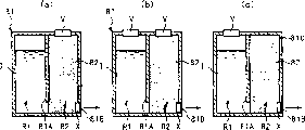
Figure 16 (a), 16 (b) and 16 (c) are used for illustrating the figure of the present invention in the application of ink tank, and this ink tank comprises two main structures of separating, and is different from aforementioned ink tank.
In these are used, two structures, just the 1st and the 2nd ink tank main structure 91 and 92 can be connected to each other at connecting hole 91A and 92A place respectively dividually.The 2nd ink tank main structure 92 is provided with ink release hole 92B, and arranges the porous ink absorption component 93 as the ink detention member of absorption and detention ink in the ink chamber of this ink tank main structure 92.In the ink chamber of the 1st ink tank main structure 91, ink 1 is directly stored, and in the 2nd ink tank main structure 92, and ink 1 is by being absorbed in the ink absorption member 93 and detention.The equipped for example valve system of person and so on shown in Fig. 4 and 11 X of ink release hole 92B, but do not draw its concrete structure here.
In the application scenario shown in Figure 16 (a), the 2nd ink tank main structure 92 is provided with a unillustrated hole as passage, and this hole is equipped with a two-way or one-way valve mechanism V, for example constitutes the aforementioned various valve systems of pressure regulating mechanism.In this ink tank, ink tank main structure 91 and 92 internal pressure are regulated by the valve system V of the 2nd ink tank main structure 92 1 sides, existence by valve system X simultaneously prevents ink leakage, and the direction that causes ink to be followed the arrow is more stably supplied.
In the application scenario shown in Figure 16 (b), except providing the structure shown in Figure 16 (a), the 1st ink tank main structure 91 is provided with a unillustrated hole, and this hole is equipped with a two-way or one-way valve mechanism V, for example constitutes the aforementioned various valve systems of pressure regulating mechanism.In this ink tank, ink tank main structure 91 and 92 internal pressure are regulated by the valve system V of the 1st ink tank main structure 91 1 sides and the valve system V of the 2nd ink tank main structure 92 1 sides, existence by valve system X simultaneously prevents ink leakage, and the direction that causes ink 1 to be followed the arrow is more stably supplied.
In the application scenario shown in Figure 16 (c), the 1st ink tank main structure 91 is provided with a unillustrated hole, and this hole is equipped with a valve system, for example constitutes the aforementioned various valve systems of pressure regulating mechanism.And then the 2nd ink tank main structure 92 is provided with a passage 92C.In this ink tank, ink tank main structure 91 and 92 internal pressure are regulated by the valve system V of the 1st ink tank main structure 91 1 sides, and the direction that causes ink to be followed the arrow is more stably supplied.Because internal pressure is regulated by the valve system V of the 1st ink tank main structure 91, so even the volume of the 2nd ink tank main structure 92 reduces, also can stably supply ink.And then the ink capacity of the 2nd ink tank main structure 92 reduces by the amount that is equivalent to arrange the 2nd ink tank main structure 92 internal volumes that ink absorption member 93 is required.So the volume that is enough to reduce the 2nd ink tank main structure 92 makes it possible to increase by the volume that the volume with respect to the 2nd ink tank main structure 92 increases by the 1st ink tank main structure 91 total ink capacity of this ink tank.
In the application scenario shown in Figure 16 (b) and 16 (c), the ink of the inner space of the 1st ink tank main structure 91 that is caused by the variation in the ambient pressure reduces the expansion or the contraction of part to be regulated, the ink that flows into or flow out the 2nd ink tank main structure 92 is controlled, thereby prevents that ink from leaking from ink release hole 92B.In other words, in the application scenario shown in Figure 16 (b) and 16 (c), flow into or the ink that flows out the 2nd ink tank main structure 92 is controlled, thereby available reducing on the ink buffer portion size that needs of the 2nd ink tank main structure 92 conventionally.Thereby, might be by reducing the volume efficiency that ink buffer portion size the improves ink tank ratio of ink tank volume (the available inks water volume with).
(the 7th embodiment)
Figure 17 (a) and 17 (b) are used for illustrating the figure of the present invention in the additional occasion of the application of ink tank, and this ink tank comprises two the ink tank main structures that can take apart each other.
In these occasions, two ink tank main structures, just the 1st and the 2nd ink tank main structure 91 and 92 can be connected to each other at connecting hole 91A and 92A place respectively dividually.In the ink chamber of the 1st ink tank main structure 91, arrange as being used for the ink bag 94 of ink detention member of storage ink.The 2nd ink tank main structure 92 is provided with ink release hole 92B.In the 1st ink tank main structure 91, ink 1 is maintained in the ink bag 94, and in the ink chamber of the 2nd ink tank main structure 92, ink 1 is directly stored.The equipped for example valve system of person and so on shown in Fig. 4 and 11 X of ink release hole 92B, but do not draw its concrete structure here.
In the occasion shown in Figure 17 (a), the 2nd ink tank main structure 92 is provided with a unillustrated hole as passage, and this hole is equipped with a two-way or one-way valve mechanism V, for example constitutes the above-mentioned various valve systems of pressure regulating mechanism.In this ink tank, the internal pressure of ink tank main structure 92 and ink bag 94 is regulated by the valve system V of the 2nd ink tank main structure 92 1 sides, existence by valve system X simultaneously prevents ink leakage, the direction supply that causes ink more stably to be followed the arrow.
And then, because internal pressure leans on the valve system V of the 2nd ink tank main structure 92 1 sides to regulate, so, also can stably supply ink even the volume of the 1st ink tank main structure 91 reduces.And then, because the ink capacity of the 1st ink tank main structure 91 reduces by the amount that is equivalent to arrange ink tank main structure 91 internal volumes that ink bag 94 is required, so be enough to reduce total ink capacity that the volume of the 1st ink tank main structure 91 makes it possible to increase by the volume that increases by the 2nd ink tank main structure 92 with respect to the 1st ink tank main structure 91 ink tank.
In the application scenario shown in Figure 17 (b), except as shown in Figure 17 (a), constituting, the 1st ink tank main structure 91 is provided with a unillustrated hole, and this hole is equipped with a two-way or one-way valve mechanism V, for example constitutes the above-mentioned various valve systems of pressure regulating mechanism.In this ink tank, the the 1st and the 2nd ink tank main structure 91 and 92 internal pressure are regulated by the valve system V of the 1st ink tank main structure 91 and the valve system V of the 2nd ink tank main structure 92, existence by valve system X simultaneously prevents ink leakage, existence by valve system X simultaneously prevents ink leakage, the direction supply that causes ink more stably to be followed the arrow.
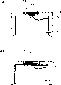
In above-mentioned each embodiment, suppose and carry out the installation of ink tank and being connected abreast of ink release pipe.Yet, in a kind of like this occasion, be that ink tank is installed from the top by rotating as shown in Figure 18 sideling, the end of the valve rod 18c of valve system 18 enters with the 3 contacted times of ink release pipe and does not occur in the time that valve system 18 is meshed with ink release pipe 3; In other words, might be located in airtightly around the equipped containment member 3A of ink release pipe 3 with before ink tank contacts, valve system 18 is opened as shown in Figure 18, causes ink leakage.
So, valve rod 18c can be as shown in Figure 19 when as shown in Figure 18 ink tank being installed in order to shorter with the contacted side of the front end of ink release pipe 3.With a kind of like this configuration, the front end of ink release pipe 3 enters with the valve rod 18c of valve system 18 with a kind of like this arrangement of time and contacts, and ink release hole 1A just opened after promptly the interface between ink release pipe 3 and ink tank sealed airtightly.Thereby, the ink leakage due to opening too early because of ink release hole 1A does not take place; In other words, ink release pipe 3 ideally is connected with ink tank.
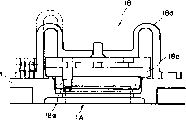
And then, might be by the valve system that has projection 18g 18 as shown in Figure 20 be set, rather than the length that changes the valve stem of valve system 18 tackles the problems referred to above.In this occasion, ink release pipe 3 directly contacts and does not directly contact with the valve rod 18c of valve system 18 with projection 18g; Thereby, should note the sealing means at the interface between ink release pipe 3 and the ink tank.
Figure 21 is the figure that is used for illustrating ink jet recording device IJRA, the ink tank compatibility in each of this equipment and the foregoing description, and with an ink-jet box and an ink jet print head compatibility that comprises any one above-mentioned ink tank.
Leading screw 5005 is rotated by rotating and reverse via driving force travelling gear 5011 and 5009 of drive motors 5013.Slide HC has a unillustrated pin of spiral fluted that is engaged in leading screw 5005, and moves back and forth along one of arrow a or b indicated direction according to the direction of rotation of leading screw 5005.An ink-jet box IJC is installed on slide HC.What label 5002 was represented is pressing plate, and the whole range of movement that it crosses over slide HC is pressed in paper or OHP film and so on recording medium on the spool.Label 5007 and 5008 representatives are as the photoelectrical coupler of initial position testing agency, and it detects the bar 5006 of slide HC so that the direction of rotation of switch motor 5013 is perhaps carried out similar operation.By label 5016 representative be supporting member, its supports the lid member 5022 that covers record head.By label 5015 representatives is to be used at the lid member 5022 inner aspirating mechanisms that form vacuum.The ink of composing images record remains on optimum level to the inkjet performance of record head to aspirating mechanism by aspirating not from record head via the hole 5023 of lid member 5022.Label 5017 is represented cleaning blade, and label 5019 is represented a member that cleaning blade can be seesawed.These members are supported on the gripper shoe 5018 of master component one side.Label 5021 is represented a bar that is used for triggering based on the performance recovery operation of suction.At cam 5020 during with slide HC motion engagement, its motion in case control from the transmission of the driving force of drive motors.
As mentioned above, according to the present invention, the main structure of ink tank is provided with the ink detention member that is arranged in the main structure, regulates the pressure regulating mechanism of the internal pressure of main structure, and the combination of valve system that opens or closes the ink release hole of main structure.Thereby, ink, and may can be suppressed so that prevent ink leakage and so in response to the fluctuation of the internal pressure of the main structure of the ink tank of the variation of environment of ink tank and so in the main structure of the ink tank that will stably supply by detention correctly all the time.
And then the setting of valve system has reduced the ink flow resistance, and making might be to ideally supplying ink with the record head of flying print compatibility.
Though described the present invention with reference to structure disclosed herein, it is not limited to given details, and the application plans to contain those modifications or the change of the scope that may fall into this improved purpose or following claims.
Claims (19)
1. one kind is used for from the ink tank of its main body via ink supply port supply ink, and described container comprises:
A kind of being used for the ink detention material of ink detention in this main body of this container;
Be used for adjusting the pressure adjustmenting mechanism of the pressure in this main body; And
A valve member that is arranged in the ink supply port;
Described valve member comprises that a blocking component that is used for blocking described ink supply port and one are used for promoting described blocking component to block the elastic component of described ink supply port; It is characterized in that: described blocking component comprises a valve rod that stretches out outside described ink supply port, and described valve rod does not reach outside the described ink tank; And
Ink tank is rotated when described ink tank is connected with a record head, and described valve rod is shorter at the part place of more approaching described ink tank center of rotation, and from its center of rotation part place head far away.
2. according to a kind of ink tank of claim 1, wherein said ink detention material is a kind of ink absorption material.
3. according to a kind of ink tank of claim 1, wherein said ink detention material is an ink cartridge that is used for the splendid attire ink.
4. according to a kind of ink tank of claim 1, wherein said ink detention member is arranged in the described main body by blow molding.
5. according to a kind of ink tank of claim 1, wherein said pressure adjustmenting mechanism comprises that the valve system of an internal pressure that is used for discharging described main body when internal pressure is higher than a predetermined value and one are used for when internal pressure is lower than a predetermined value ambient pressure introduced at least one of valve system in the described main body.
6. according to a kind of ink tank of claim 1, wherein when described ink tank was installed on the record head, an ink tubes of this record head was withstood this valve rod, overcomes this elastic component and promotes described blocking component, so that open ink supply port.
7. according to a kind of ink tank of claim 1, wherein said main body comprises one group of ink chamber that is used for holding ink, these ink chamber are fluid communication with each other, and wherein said ink detention material is located at least one described ink chamber, and described pressure adjustmenting mechanism is located at least one described ink chamber.
8. according to a kind of ink tank of claim 7, wherein said ink chamber can separate.
9. one kind is used for from the ink tank of its main body via an ink supply port supply ink, and described container comprises:
A kind of being used for the ink detention material of ink detention in this main body of this container;
Be used for adjusting the pressure adjustmenting mechanism of the pressure in this main body; And
A valve member that is arranged in the ink supply port, described valve member comprise that a blocking component that is used for blocking described ink supply port and one are used for promoting described blocking component to block the elastic component of described ink supply port;
It is characterized in that: described blocking component comprises a valve rod that stretches out outside described ink supply port, described valve rod does not reach outside the ink tank; And
Ink tank is rotated when described ink tank is connected with a record head, and described valve rod has an outside protuberance from described ink tank center of rotation part place far away, and the length of described protuberance does not reach outside the described container.
10. according to a kind of ink tank of claim 9, wherein said ink detention material is a kind of ink absorption material.
11. according to a kind of ink tank of claim 9, wherein said ink detention material is an ink cartridge that is used for the splendid attire ink.
12. according to a kind of ink tank of claim 9, wherein said ink detention member is arranged in the described main body by blow molding.
13. according to a kind of ink tank of claim 9, wherein said pressure adjustmenting mechanism comprises that the valve system of an internal pressure that is used for discharging described main body when internal pressure is higher than a predetermined value and one are used for when internal pressure is lower than a predetermined value ambient pressure introduced at least one of valve system in the described main body.
14. according to a kind of ink tank of claim 9, wherein when described ink tank was installed on the record head, an ink tubes of this record head was withstood this valve rod, overcomes this elastic component and promotes described blocking component, so that open ink supply port.
15. a kind of ink tank according to claim 9, wherein said main body comprises one group of ink chamber that is used for holding ink, these ink chamber are fluid communication with each other, and wherein said ink detention material is located at least one described ink chamber, and described pressure adjustmenting mechanism is located at least one described ink chamber.
16. according to a kind of ink tank of claim 15, wherein said ink chamber can separate.
17. a print cartridge is included in an ink tank and an ink jet print head that is configured to spray the ink of supplying via the described ink supply port of described ink tank of being defined in any one in claim 1~8 or 9~16.
18. according to a kind of print cartridge of claim 17, wherein said ink tank can separate with described ink jet print head.
19. according to a kind of print cartridge of claim 17, wherein said ink jet print head is provided with the electric transducer that is used for producing the heat energy that sprays ink.
Applications Claiming Priority (4)
| Application Number | Priority Date | Filing Date | Title |
|---|---|---|---|
| JP117066/2000 | 2000-04-18 | ||
| JP2000117066 | 2000-04-18 | ||
| JP103825/2001 | 2001-04-02 | ||
| JP2001103825A JP2002001988A (en) | 2000-04-18 | 2001-04-02 | Ink tank and ink jet cartridge |
Publications (2)
| Publication Number | Publication Date |
|---|---|
| CN1318471A CN1318471A (en) | 2001-10-24 |
| CN1192893C true CN1192893C (en) | 2005-03-16 |
Family
ID=26590337
Family Applications (1)
| Application Number | Title | Priority Date | Filing Date |
|---|---|---|---|
| CNB011170069A Expired - Fee Related CN1192893C (en) | 2000-04-18 | 2001-04-18 | Ink container and ink-jet ink box |
Country Status (10)
| Country | Link |
|---|---|
| US (1) | US6511168B2 (en) |
| EP (1) | EP1147903B1 (en) |
| JP (1) | JP2002001988A (en) |
| KR (1) | KR100385274B1 (en) |
| CN (1) | CN1192893C (en) |
| AU (1) | AU761474B2 (en) |
| CA (1) | CA2344297C (en) |
| DE (1) | DE60106507T2 (en) |
| SG (1) | SG90245A1 (en) |
| TW (1) | TW521039B (en) |
Families Citing this family (34)
| Publication number | Priority date | Publication date | Assignee | Title |
|---|---|---|---|---|
| WO2003041963A1 (en) * | 2001-11-12 | 2003-05-22 | Seiko Epson Corporation | Ink cartridge |
| JP4086515B2 (en) * | 2002-02-15 | 2008-05-14 | キヤノン株式会社 | Seal member, connection structure using the same, and liquid jet recording head |
| DE10206696B4 (en) * | 2002-02-18 | 2006-01-26 | Pelikan Hardcopy Production Ag | Ink cartridge with valve |
| EP1512536B2 (en) † | 2002-06-11 | 2012-08-01 | Seiko Epson Corporation | Ink cartridge |
| JP3772859B2 (en) * | 2002-07-09 | 2006-05-10 | セイコーエプソン株式会社 | Ink cartridge and ink cartridge decompression package |
| JP3991853B2 (en) * | 2002-09-12 | 2007-10-17 | セイコーエプソン株式会社 | ink cartridge |
| US6877849B2 (en) * | 2003-01-23 | 2005-04-12 | Hewlett-Packard Development Company, L.P. | Printing system with high volumetric ink container vessel |
| CN100418777C (en) * | 2003-10-16 | 2008-09-17 | 理想科学工业株式会社 | Ink container |
| US7325913B2 (en) | 2003-11-25 | 2008-02-05 | Brother Kogyo Kabushiki Kaisha | Ink cartridge |
| US7334888B2 (en) * | 2003-11-25 | 2008-02-26 | Brother Kogyo Kabushiki Kaisha | Ink cartridge |
| JP4517659B2 (en) * | 2003-11-25 | 2010-08-04 | ブラザー工業株式会社 | Ink cartridge and valve device |
| JP4517637B2 (en) * | 2003-12-08 | 2010-08-04 | ブラザー工業株式会社 | Ink cartridge and ink cartridge package |
| US7384136B2 (en) | 2003-11-25 | 2008-06-10 | Brother Kogyo Kabushiki Kaisha | Ink cartridge |
| CN1764547B (en) * | 2004-02-09 | 2010-05-26 | 兄弟工业株式会社 | Ink cartridge |
| TWI255233B (en) * | 2004-02-09 | 2006-05-21 | Brother Ind Ltd | Ink cartridge |
| JP4670335B2 (en) * | 2004-12-13 | 2011-04-13 | ブラザー工業株式会社 | ink cartridge |
| US7455398B2 (en) * | 2004-12-13 | 2008-11-25 | Brother Kogyo Kabushiki Kaisha | Ink cartridge |
| JP4665500B2 (en) * | 2004-12-13 | 2011-04-06 | ブラザー工業株式会社 | ink cartridge |
| JP4735344B2 (en) * | 2005-03-28 | 2011-07-27 | セイコーエプソン株式会社 | Liquid container |
| JP2007007902A (en) * | 2005-06-28 | 2007-01-18 | Fujifilm Holdings Corp | Ink tank and inkjet recorder |
| US20070035596A1 (en) * | 2005-08-10 | 2007-02-15 | Lexmark International, Inc. | Ink jet cartridge |
| JP4774896B2 (en) * | 2005-09-29 | 2011-09-14 | ブラザー工業株式会社 | ink cartridge |
| WO2007109990A1 (en) * | 2006-03-24 | 2007-10-04 | Print-Rite Technology Development Co., Ltd Of Zhuhai | A valve body, a valve assembly and an ink cartridge |
| JP4942163B2 (en) * | 2006-08-03 | 2012-05-30 | キヤノン株式会社 | Ink storage container |
| JP5011922B2 (en) * | 2006-09-29 | 2012-08-29 | ブラザー工業株式会社 | Ink cartridge and inkjet recording system |
| US20080165214A1 (en) * | 2007-01-05 | 2008-07-10 | Kenneth Yuen | Ink cartridge fluid flow arrangements and methods |
| US8342661B2 (en) | 2007-12-19 | 2013-01-01 | Canon Finetech Inc. | Ink supplying apparatus, inkjet printing apparatus, inkjet printing head, ink supplying method and inkjet printing method |
| JP5431856B2 (en) * | 2009-10-08 | 2014-03-05 | スタンダード・オフィス・サプライ・カンパニー・リミテッド | ink cartridge |
| JP6123296B2 (en) * | 2013-01-07 | 2017-05-10 | セイコーエプソン株式会社 | Ink for ink jet recording and recorded matter |
| JP5610001B2 (en) * | 2013-01-18 | 2014-10-22 | 株式会社リコー | Liquid container, image forming apparatus, and method for assembling liquid container |
| JP6330331B2 (en) * | 2014-01-14 | 2018-05-30 | セイコーエプソン株式会社 | Liquid container, liquid ejecting system, liquid ejecting apparatus |
| EP3078497A1 (en) * | 2015-04-09 | 2016-10-12 | Pelikan Hardcopy Production AG | Ink cartridge for use in an ink jet printer |
| JP6536178B2 (en) * | 2015-05-29 | 2019-07-03 | セイコーエプソン株式会社 | Liquid container |
| JP2018104740A (en) * | 2016-12-22 | 2018-07-05 | ローム・アンド・ハース電子材料株式会社 | Electroless plating method |
Family Cites Families (18)
| Publication number | Priority date | Publication date | Assignee | Title |
|---|---|---|---|---|
| US2935075A (en) | 1954-11-01 | 1960-05-03 | Bendix Aviat Corp | Relief valve |
| CA2019290A1 (en) | 1990-01-12 | 1991-07-12 | Bruce Cowger | Pressure-sensitive accumulator for ink-jet pens |
| US5040002A (en) | 1990-03-16 | 1991-08-13 | Hewlett-Packard Company | Regulator for ink-jet pens |
| CA2110411A1 (en) | 1991-06-07 | 1992-12-10 | Leane Kristine Davis | Resilient squeeze bottle employing air check valve |
| ATE179122T1 (en) * | 1992-02-24 | 1999-05-15 | Canon Kk | A LIQUID CONTAINER, AN INKJET CARTRIDGE HAVING A LIQUID CONTAINER, AND AN INKJET RECORDING APPARATUS HAVING SUCH A CARTRIDGE |
| CA2100977C (en) | 1992-07-24 | 2000-02-08 | Noribumi Koitabashi | Ink container, ink and ink jet recording apparatus using ink container |
| US5619239A (en) * | 1993-11-29 | 1997-04-08 | Canon Kabushiki Kaisha | Replaceable ink tank |
| TW373595U (en) | 1994-05-25 | 1999-11-01 | Canon Kk | An ink container and an ink jet recording apparatus using the same |
| JPH08174860A (en) * | 1994-10-26 | 1996-07-09 | Seiko Epson Corp | Ink cartridge for ink jet printer |
| JP3713632B2 (en) * | 1994-12-28 | 2005-11-09 | 富士写真フイルム株式会社 | Ink cartridge and inkjet printer |
| JP3251845B2 (en) * | 1995-04-17 | 2002-01-28 | キヤノン株式会社 | Liquid container for applying negative pressure, method for manufacturing the container, ink jet cartridge integrating the container with an ink jet recording head, and ink jet recording apparatus |
| US5953030A (en) | 1995-04-24 | 1999-09-14 | Canon Kabushiki Kaisha | Ink container with improved air venting structure |
| JP3343876B2 (en) | 1996-03-07 | 2002-11-11 | キヤノン株式会社 | Valve element, valve, ink tank provided with the same, and ink jet cartridge having the ink tank |
| JPH10217495A (en) * | 1997-02-04 | 1998-08-18 | Minolta Co Ltd | Ink cartridge and ink supply unit |
| US6050681A (en) * | 1997-01-14 | 2000-04-18 | Minolta Co., Ltd. | Ink cartridge and ink supplying apparatus |
| JP3880232B2 (en) * | 1997-12-25 | 2007-02-14 | キヤノン株式会社 | Liquid supply method, liquid supply system using the liquid supply method, and ink tank |
| US6443567B1 (en) * | 1999-04-27 | 2002-09-03 | Canon Kabushiki Kaisha | Liquid ejecting cartridge and recording device using same |
| JP2001001542A (en) * | 1999-06-24 | 2001-01-09 | Canon Inc | Liquid supply method, capillary force generating member storing container used for the liquid supply method, and liquid supply container |
-
2001
- 2001-04-02 JP JP2001103825A patent/JP2002001988A/en not_active Withdrawn
- 2001-04-17 US US09/835,393 patent/US6511168B2/en not_active Expired - Fee Related
- 2001-04-17 EP EP01109506A patent/EP1147903B1/en not_active Expired - Lifetime
- 2001-04-17 DE DE60106507T patent/DE60106507T2/en not_active Expired - Fee Related
- 2001-04-17 SG SG200102463A patent/SG90245A1/en unknown
- 2001-04-18 CA CA002344297A patent/CA2344297C/en not_active Expired - Fee Related
- 2001-04-18 AU AU38732/01A patent/AU761474B2/en not_active Ceased
- 2001-04-18 KR KR10-2001-0020628A patent/KR100385274B1/en not_active IP Right Cessation
- 2001-04-18 CN CNB011170069A patent/CN1192893C/en not_active Expired - Fee Related
- 2001-04-18 TW TW090109318A patent/TW521039B/en not_active IP Right Cessation
Also Published As
| Publication number | Publication date |
|---|---|
| AU3873201A (en) | 2002-01-31 |
| DE60106507T2 (en) | 2005-10-20 |
| US6511168B2 (en) | 2003-01-28 |
| AU761474B2 (en) | 2003-06-05 |
| KR20010098679A (en) | 2001-11-08 |
| KR100385274B1 (en) | 2003-05-23 |
| EP1147903B1 (en) | 2004-10-20 |
| JP2002001988A (en) | 2002-01-08 |
| CA2344297A1 (en) | 2001-10-18 |
| SG90245A1 (en) | 2002-07-23 |
| EP1147903A1 (en) | 2001-10-24 |
| TW521039B (en) | 2003-02-21 |
| CN1318471A (en) | 2001-10-24 |
| DE60106507D1 (en) | 2004-11-25 |
| CA2344297C (en) | 2005-06-07 |
| US20010048456A1 (en) | 2001-12-06 |
Similar Documents
| Publication | Publication Date | Title |
|---|---|---|
| CN1192893C (en) | Ink container and ink-jet ink box | |
| CN1281417C (en) | Liquid container, liquid using device, recording device and ink-jet box | |
| CN1114530C (en) | Ink box of ink jet printer | |
| CA2371027C (en) | Pressure adjustment chamber, ink-jet recording head having the same, and ink-jet recording device using the same | |
| CN1201934C (en) | Ink-jet head storage structure and liquid filling method | |
| CN1030051C (en) | Liquid container, recording head using same and recording apparatus using same | |
| CN1081548C (en) | Ink jet pipe ink nozzle and printer | |
| CN1251875C (en) | Ink container, record head and corresponding recording device | |
| CN1280104C (en) | Liquid container and ink-jet printing apparatus | |
| CN2703647Y (en) | Ink box and vacuum package product containing said ink-box | |
| CN1647931A (en) | Liquid container | |
| CN1071371A (en) | The record-header and the pen recorder of liquid container and this container of use | |
| CN100345686C (en) | Liquid cartridge | |
| CN1091037C (en) | Valve member, valve, ink container and ink cartridge having same | |
| CN1519127A (en) | Liquid vessel, its bearing and recording head casket | |
| US7641305B2 (en) | Liquid ejecting apparatus | |
| CN2887601Y (en) | Print cartridge | |
| CN1269649C (en) | Cartridge for jet-ink recording device | |
| CN1304835A (en) | Valve body and liquid storage container for liquid discharge device using said valve body | |
| CN1891469A (en) | Ink cartridge for ink-jet recording equipment and ink-jet recording equipment | |
| JP2002211003A (en) | Ink jet recorder and its pressure damper fixing method |
Legal Events
| Date | Code | Title | Description |
|---|---|---|---|
| C10 | Entry into substantive examination | ||
| SE01 | Entry into force of request for substantive examination | ||
| C06 | Publication | ||
| PB01 | Publication | ||
| C14 | Grant of patent or utility model | ||
| GR01 | Patent grant | ||
| C17 | Cessation of patent right | ||
| CF01 | Termination of patent right due to non-payment of annual fee |
Granted publication date: 20050316 Termination date: 20100418 |