JP3772859B2 - Ink cartridge and ink cartridge decompression package - Google Patents
Ink cartridge and ink cartridge decompression package Download PDFInfo
- Publication number
- JP3772859B2 JP3772859B2 JP2003189827A JP2003189827A JP3772859B2 JP 3772859 B2 JP3772859 B2 JP 3772859B2 JP 2003189827 A JP2003189827 A JP 2003189827A JP 2003189827 A JP2003189827 A JP 2003189827A JP 3772859 B2 JP3772859 B2 JP 3772859B2
- Authority
- JP
- Japan
- Prior art keywords
- ink
- ink cartridge
- atmospheric
- atmosphere
- flow path
- Prior art date
- Legal status (The legal status is an assumption and is not a legal conclusion. Google has not performed a legal analysis and makes no representation as to the accuracy of the status listed.)
- Expired - Fee Related
Links
Images


Classifications
-
- B—PERFORMING OPERATIONS; TRANSPORTING
- B41—PRINTING; LINING MACHINES; TYPEWRITERS; STAMPS
- B41J—TYPEWRITERS; SELECTIVE PRINTING MECHANISMS, i.e. MECHANISMS PRINTING OTHERWISE THAN FROM A FORME; CORRECTION OF TYPOGRAPHICAL ERRORS
- B41J2/00—Typewriters or selective printing mechanisms characterised by the printing or marking process for which they are designed
- B41J2/005—Typewriters or selective printing mechanisms characterised by the printing or marking process for which they are designed characterised by bringing liquid or particles selectively into contact with a printing material
- B41J2/01—Ink jet
- B41J2/17—Ink jet characterised by ink handling
- B41J2/175—Ink supply systems ; Circuit parts therefor
- B41J2/17503—Ink cartridges
- B41J2/17513—Inner structure
Landscapes
- Ink Jet (AREA)
- Packages (AREA)
Abstract
Description
【0001】
【発明の属する技術分野】
本発明は、ノズル開口からインク滴を吐出して文字や画像などのデータを印刷する記録ヘッドを搭載したインクジェット記録装置のキャリッジ上に、着脱可能に装着され、インクを記録ヘッドへ供給するインクカートリッジに関する。特に、本発明は大気開放弁を有するインクカートリッジおよびそれを減圧状態でパッケージするインクカートリッジ減圧包装品に関する。
【0002】
【従来の技術】
インクジェット記録装置の記録ヘッドにインクを供給するインクカートリッジは、インクを保持するインク室と、インク室と連通し、かつインク供給針が挿入されこれを介して記録ヘッドへインクを供給するインク供給口と、インク供給口からインクが排出されインク室内のインクの量が減少するに従って、インク室に大気を導入する大気流路を備えている。
【0003】
【発明が解決しようとする課題】
しかしながら、大気流路を通じてインク室がインクカートリッジの外部と連通していることにより、インクカートリッジがインクジェット記録装置に装着されていない場合であっても、インク室内のインクが大気流路を介して外部に漏れ出したり、インク中の溶媒が蒸発して、インクが増粘するなどの変質があった。
【0004】
そこで本発明は、上記の課題を解決することのできる、インクカートリッジおよびインクカートリッジ減圧包装品を提供することを目的とする。この目的は特許請求の範囲における独立項に記載の特徴の組み合わせにより達成される。また従属項は本発明の更なる有利な具体例を規定する。
【0005】
【課題を解決するための手段】
即ち、本発明の第1の形態によるインクカートリッジは、インクを保持するインク収容部と、インク収容部と大気とを連通する大気流路と、大気流路中に設けられた弁機構を備え、弁機構は、インク収容部側と大気側とを区画する隔壁に設けられた連通孔を、インク収容部側から大気側に向かう方向に封止する大気弁部材を備え、大気弁部材には、大気側からインク収容部側に向かう外部からの力を受け大気流路を開放する当接部を備えたことを特徴とする。これにより、インクカートリッジがインクジェット記録装置に装着されていない場合において、インクカートリッジの大気流路を確実に塞ぎ、インクがインクカートリッジの外部へ漏れ出したり、インク中の溶媒が蒸発することによるインクの増粘等のインク特性変化を防ぐことができる。
【0006】
上記インクカートリッジにおいて、大気流路は、大気に近い順に蛇行した通路ならびに通気性および撥液性を有するフィルタを有し、弁機構は、フィルタとインク収容部との間に設けられてもよい。これにより、弁機構から大気流路の大気側へインクが流出した場合であっても、インクがさらに外部へ流出することをフィルタが防ぐことができる。
【0007】
上記インクカートリッジは、大気弁部材をインク収容部側から大気側に向かう方向に押圧する弾性力を有する押圧部材を備えてもよい。これにより、インクカートリッジが記録装置に装着されていない場合に、インクカートリッジの大気流路をより確実に塞ぐことができる。
【0008】
上記インクカートリッジは、大気弁部材の当接部と当接して大気流路を開放する軸揺動可能なハンマーを有してもよい。これにより、インクカートリッジが記録装置に装着された場合に、インクカートリッジの大気流路をハンマーで確実に開放することができる。
【0009】
上記インクカートリッジにおいて、ハンマーは、インクカートリッジの記録装置への装着方向に対して垂直方向に軸揺動してもよい。これにより、インクカートリッジが記録装置に装着される場合に、ハンマーが軸揺動する距離を大きくすることができる。よって、インクカートリッジが記録装置に装着された場合に、ハンマーにより大気流路をより確実に開放することができる。
【0010】
上記インクカートリッジは、インクカートリッジの記録装置への装着方向に対してほぼ平行な方向に移動する大気弁押圧部材を有し、当接部が大気弁押圧部材により押圧されることにより大気流路を開放してもよい。これにより、インクカートリッジの幅方向を広くすることなく、インクカートリッジが記録装置に装着される場合に大気弁押圧部材が移動する距離を大きくすることができる。よって、インクカートリッジが記録装置に装着されるのに伴い、大気弁押圧部材により大気流路を確実に開放することができる。
【0011】
上記インクカートリッジにおいて、大気弁部材は、インクカートリッジの記録装置への装着方向に延びて、連通孔よりも大気側に突出する突出部を有し、突出部は大気弁押圧部材により押圧可能に形成されてもよい。これにより、インクカートリッジが記録装置に装着されるのに伴って、突出部が大気押圧部材により装着方向に押圧されて、大気流路をより確実に開放することができる。
【0012】
上記インクカートリッジは、大気弁部材を、インクカートリッジの記録装置への装着方向に弾性的に付勢する弾性部材をさらに備えてもよい。これにより、インクカートリッジが記録装置に装着されていない場合に、インクカートリッジの大気流路をより確実に塞ぐことができる。
【0013】
上記インクカートリッジにおいて、当接部がフィルムを介してハンマーにより押圧されてもよい。これにより、簡便な構成で、ハンマーにより当接部を押圧することができる。
【0014】
上記インクカートリッジにおいて、大気弁押圧部材を収容した部屋の記録装置に押圧される側がフィルムにより封止されてもよい。これにより、簡便な構成で、大気弁押圧部材を収容した部屋の外部から大気弁押圧部材を押圧することができる。
【0015】
インクカートリッジ減圧包装品は、上記インクカートリッジと、インクカートリッジを覆う略袋状の外包装とを備え、外包装の内部を減圧してインクカートリッジを密封した。よって、インクカートリッジが外包装に収容された場合に、外包装の内部の減圧に起因する負圧により、大気開放弁は大気流路を遮断する方向に力を受ける。よって、大気開放弁が負圧で開放することを防ぎ、大気開放弁を通じてインクがインクカートリッジから漏れ出すことを確実に防止することができる。
【0016】
なお上記の発明の概要は、本発明の必要な特徴の全てを列挙したものではなく、これらの特徴群のサブコンビネーションも又発明となりうる。
【0017】
【発明の実施の形態】
以下、発明の実施の形態を通じて本発明を説明するが、以下の実施形態は特許請求の範囲にかかる発明を限定するものではなく、又実施形態の中で説明されている特徴の組み合わせの全てが発明の解決手段に必須であるとは限らない。
【0018】
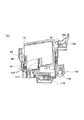
図1は、本発明の第1の実施形態にかかるインクカートリッジ10の前面斜視図であり、図2は、図1のインクカートリッジ10の背面斜視図である。本実施形態のインクカートリッジは、インクジェット記録装置のキャリッジ上に装着された状態では大気流路を通じてインク室(インク収容部)とインクカートリッジ10の外部(大気)とが連通されており、これによりインクを記録ヘッドに供給可能に構成されている。一方、キャリッジ上に装着されていない状態では、大気流路は弁機構により遮断されてインクの漏れ出しやインク中の溶媒の蒸発を防止するように構成されている。さらに、本実施形態のインクカートリッジ10は、減圧状態で包装されている場合に、より確実に大気流路を遮断する構造となっている。
【0019】
本実施形態のインクカートリッジ10は、図4に示すようにインクを収容するインク室を構成するように背面側が開口したインク室本体15と、このインク室本体15の開口を振動溶着や熱融着等により封止する蓋13とを有している。インク室本体15の前面壁には後述する大気流路を構成する溝が形成されていて、図1に示すフィルム11をインク室本体15の前面のほぼ全域に貼着することでその溝が封止されて、大気流路として機能するよう構成されている。他方、インク室本体15の開口の一部をフィルムで封止した後、開口の全面を蓋13により封止することで内部にインク室が画定され、単体のインク容器として機能する。
【0020】
インクカートリッジ10の底面にはインク室とインク流路を介して連通する中空のインク供給口14が形成されている。インク供給口14は工場出荷時には液密のフィルム25が貼られてインク漏れが防止されているが、このフィルム25はインクジェット記録装置に装着される際にインク供給針により破断される。なお、インク供給口14内には、インクカートリッジ10がインクジェット記録装置に装着されていない状態のときにはその流路を遮断する弁機構を設けてもよく、この構造を有するインクカートリッジ10は、インクがまだ残存している状態であってもインクジェット記録装置から何回でも着脱することが可能である。
【0021】
図1に見られるように、インクカートリッジ10の前面から見て右側側面には回路基板27が装着されている。この回路基板27には、裏面に例えばEEPROMなどの半導体記憶装置が備えられ、前面に複数の接点端子28が配列されている。これら接点端子28はインクカートリッジ10がインクジェット記録装置に装着されているときに外部の制御装置の電極と接触する位置に配設されていて、随時半導体記憶装置からインクに関する情報、例えばインクの仕様や消費量に関するデータが読み書きされる。この特徴により、インクカートリッジ10がインクジェット記録装置から取り外されてもインクに関する必要な情報はインクカートリッジ10自体に保持され、再度インクジェット記録装置に装着されたときにその情報を読み出すことで適切な印字制御をおこなうことが可能となる。なお、回路基板27はインクカートリッジ10から着脱可能にしてもよく、また半導体記憶装置自体はインクカートリッジ10の異なる場所に取り付けられ、接点端子28とは結線等を介して接続するようにしてもよい。
【0022】
また、インクカートリッジ10には、その対向する2つの側面の中央部分からそれぞれ上方に延びるように可撓性の係止レバー18と、把持用レバー19とが形成されている。これらのレバー18、19は、インク室本体15と一体に、例えばポリプロピレン(PP)を用いて形成されている。
【0023】
更に、インクカートリッジ10の前面側の、インク供給口14の近傍かつ前面の幅方向中央側には、インク供給口14へのインク供給針112の挿入方向に延びるスリット部16が設けられている。図3を参照して後述するように、このスリット部16は、インクカートリッジ10がキャリッジ110に装着される際に、キャリッジ上のインク供給針112の近傍から直立するように設けられたガイド突起117と係合することで、インク供給口14がインク供給針112に到達する前にインク供給口14の開口面がインク供給針に対して正確に直交する向きとなるように規制される。それにより、インク供給針112は正確に位置合わせされてインク供給口14に挿入される。
【0024】
さらにまた、インクカートリッジ10における前面の下方側の一端部には、インク室本体15とは別部材からなる識別部材60が設けられている。この識別部材60はインクカートリッジ10の種類に応じて、例えばインクの色毎に異なる形状をしており、後述するキャリッジ110上の識別突起118と、鍵と鍵穴が嵌合するように係合するよう設計されている。これによりインクカートリッジ10のキャリッジ110の所定箇所以外への挿入、いわゆる誤挿入が防止される。この識別部材60には後で詳細に説明するハンマー62が一体的に成形されている。
【0025】
図3は本発明のインクカートリッジ10がインクジェット記録装置のキャリッジ110上に装着された状態を示す側面断面図である。図3(a)は装着途中の状態を、図3(b)は完全に装着された状態を示す。キャリッジ110は、インクジェット記録装置のシャフト116上に、主走査方向に往復運動可能に載置される。このキャリッジ110には、それぞれ異なるインクが収容された複数のインクカートリッジ10が装着できるように構成されている。具体的には例えばイエロー、シアン、マゼンタ、ブラックの4つの異なる色のインクが収容された4つの異なるインクカートリッジ10が装着されるようになっていて、フルカラーの印刷が可能である。なお、異なるインクとは、色が異なるだけに限定されず、同色であっても品質や組成の異なるインクが収容された複数のインクカートリッジ10がキャリッジ110に装着されてもよい。
【0026】
このキャリッジ110にインクカートリッジ10を装着するとき、インクカートリッジ10の左右の側面から延びるレバー18、19を親指と人差し指でつまんで、キャリッジ110の上から直下に向かって押し込む。その際、インク室本体15の一側面に形成されたスリット部16が、キャリッジ110上のインク供給針112の近傍から直上に延びるガイド突起117と係合する。このスリット部16とガイド突起117とにより、インクカートリッジ10を誤って逆向きに装着できないようになっている。インクカートリッジ10が完全に嵌合すると、係止レバー18の一部に設けられた係合突起18Aが係合溝120と係合し、係止レバー18をインク室本体15側に倒さない限りキャリッジ110からは外れない構造となっている。またインクカートリッジ10がキャリッジ110に装着されると、記録ヘッド119と連通するインク供給針112がインクカートリッジ10の底面に形成されたインク供給口14内に挿入され、インクカートリッジ10のインク室と記録ヘッドとが連通する。この状態で、記録ヘッド119からインクを吐出する様に駆動されると、インクカートリッジ10内のインクが記録ヘッド119へ供給される。なお、把持用レバー19は、インクカートリッジ10を安定して手で保持するために形成されるが、キャリッジ110に係合凹部を形成し、この係合凹部と係合する様に係合突起を形成しても良い。
【0027】
インクカートリッジ10は、インク室と大気とを連通させる大気流路を有している。この大気流路は、後述するように、インク室と連通するインク側通路30と、大気と連通する大気側通路40とに大きく分けられ、その両通路の間に大気開放弁(大気弁部材)70が配設されている。
【0028】
図4は、インクカートリッジ10を前面側から見た分解斜視図である。図5(a)はインク室本体15を前面から見て、フィルム11、円形凹部310に嵌合される膜弁308とキャップ303、および、両者の間に介在するコイルバネ306を取り除いた平面図、図5(b)は円形凹部310に嵌合される膜弁308とキャップ303および両者の間に介在するコイルバネ306を取り除いた斜視図、図5(c)はインクカートリッジ10を底面から見た平面図、図6(a)〜(c)はその背面を示し、蓋13を取り除いた平面図である。
【0029】
図4および図5(a)、(b)および(c)ならびに図6(a)を参照しながら本発明の実施例であるインクカートリッジ10の構造について説明する。
始めにインク通路について説明する。図5(a)および図5(b)に示す通り、管状のインク供給口14はその内壁に形成された孔301から溝302の一端に通じており、溝302の他端はキャップ303の表面に形成された溝304と連通する。キャップ303にはその中央に貫通孔305が形成されている。一方、エラストマー等の可撓性材料からなる膜弁308には中心孔309が形成されており、この中心孔309は円形凹部310の底面に形成された封止部である突部312と対抗するよう形成されており、この中心孔309と突部312とが接離することによりインク室側とインク供給口14側との非連通、連通が制御される。より詳細には、記録ヘッド119からインクが排出されていない状態では、中心孔309と突部312とは当接してインク流路を遮断している。一方、記録ヘッド119からインクが排出されると、膜弁308を境にインク供給口14側の圧力が減少し、所定の圧力まで下がったときにその圧力(負圧)によって膜弁308が変形し、中心孔309が突部312から離れ、インク室側とインク供給口14側が連通してインク室のインクがインク供給口14に供給される。上記円形凹部310の底面には2つの通孔314が形成されており、この通孔314はインクカートリッジ10の背面側まで貫通している。
【0030】
次にインクカートリッジ10を、その背面側を示す図6(a)を用いて説明する。インクカートリッジ10の背面側にはインクを収容するインク室が形成されている。このインク室は周壁320によってその内部に形成される第1のインク室322と、その外側の第2のインク室324とに区画されている。第1のインク室322を囲む周壁320及び周壁320と同じ高さで形成された第2円形壁328等には図示しないフィルムが貼りつけられ第1のインク室322が区画されている。
【0031】
2つの通孔314は第1のインク室322側に設けられた、背の低い第1円形壁326と、背の高い第2円形壁328によって区画された凹部330と連通している。第1円形壁326の上縁は第2円形壁328の上縁よりも低く設定されており、板状のフィルタ等が形成可能に構成されている。第2円形壁328にはその一部に切り欠き部332が形成されており、凹部330は第2円形壁328の切り欠き部332を介して、表側へと通ずる通孔334と連通している。図5(a)に見られるように、通孔334は表側に形成された壁336により区画された涙状の凹部338、通孔340を介して再び背面側へと通じている。通孔340と連通する背面側の凹部にはフィルタ342が封入されている。更に通孔340は、フィルタ342から切り欠き部343、周壁320と周壁320と同じ高さに形成された隔壁347により形成された延長溝346を介して第1のインク室322へと通じている。
【0032】
第1のインク室322の右下コーナー部分には、表面側へと通ずる通孔350が穿たれており、図5(a)に示す連通溝351を介して、図5(c)に示すインクカートリッジ10の底面に形成された通孔352へと通じている。この通孔352は凹部354を介して切り欠き356へと通じている。この切り欠き356は背面側に形成された第2のインク室324へと通じている。
なお、この凹部354は、図示しないフィルムにより封止されて大気流路の一部を構成する空間が形成される。
【0033】
次に大気流路の構造について説明する。
図5(a)に見られるように、インク室本体15の表面側にはその長さがインクの蒸発を抑制することが可能な程度の大きさと長さで形成された、蛇行した1本の溝を図4に示すフィルム11で封止することにより形成された通路52が形成され、この通路52の一端は大気大気開口54として開放されている。通路52の他端370は、矩形の凹部372とつながっており、凹部372の底部にはインク室本体15の背面側に貫通している通孔48が形成されている。この凹部372には撥インク性と通気性がある材料からなるフィルタ50(図4参照)が凹部372の中間に位置するように配置され、凹部372の一方を通路52と連通する部屋に、また凹部372の他方を通孔48と連通する部屋に区画している。このフィルタ50によって、大気中の塵埃や水分が取り除かれるとともに、インク室側から流れ出してきたインクを外部に漏らさないようにしている。通孔48から背面側へと通過した大気は、図6に示した周壁374によって区画された溝47およびその溝47の底部に形成された通孔46を介して再び表面へと通じている。通孔46は表面に設けられた溝45に通じている。溝45の他方の端部には、背面側に通じる通孔44が形成されている。インク室本体15の表面側一面にフィルム11が貼りつけられるので、溝45もこのフィルム11により封止される。大気は通孔46、溝45および通孔44により形成される一本の通気路を通過することになる。このようにして大気は通孔44を介して再び裏側へと流れ込む。通孔44は縦長の溝43を介してその下部に穿たれた通孔42へと通じ、再び表側に流れる。表側で通孔42は溝41を介して内外連通孔26へと通じている。内外連通孔26は裏側で凹部36を介して通孔35へと通じている。図5(a)に見られるように通孔35は溝34を介して通孔33と連通し、図6(a)に示すようにこの通孔33は上方向へ向かう溝380と連通しており、溝380は下方向へ向かう溝381を介して第2のインク室324の上方に連通している。
【0034】
図4に戻って、インク室本体15には、インク収容室と内外連通孔26とを連通するインク側通路30と、内外連通孔26と大気とを連通する大気側通路40とが形成されている。これら両流路が連通することで一本の大気流路が構成され、大気からインク収容室に大気を導入する構造となっている。本実施形態のインクカートリッジ10には、この内外連通孔26を封止または開放する弁機構が配置されている。
【0035】
図4に示すように、弁機構を構成する大気開放弁70は大径の基部72と小径の突部74とを一体に成形してなり、突部74が、インクカートリッジ10の背面側、すなわち図4の後ろ側から内外連通孔26に挿入されている。突部74は、大気開放弁70が装着された状態のとき、突部74の先端の一部が内外連通孔26からインクカートリッジ10の前面側に突出する長さを有している。
【0036】
屈曲した板バネからなる押圧部材80は大気開放弁70をインクカートリッジ10の背面側から押圧し、通常の状態では大気開放弁70の基部72の内外連通孔26側は、押圧部材80の弾性力により内外連通孔26が形成された壁に当接して封止されている。なお、押圧部材80は板バネに限られず、例えばコイルバネまたは樹脂弾性体であってもよい。押圧部材80において板バネの一端84、82はインク室本体15に固定され、他端86は大気開放弁70を押圧するように構成されている。これにより、通常の状態において外部とインク室の内部が連通されないので、インクカートリッジ10をインクジェット記録装置に装着しない場合に、インクがインク室から漏れ出したり、インク室に保持されるインクの溶媒が蒸発したりすることを防ぐことができる。なお、押圧部材80は、図7において概略的に示すように、インクカートリッジ10の内壁の一部22とフィルム88との間の空間212に配設されており、この空間212は大気流路の一部を構成する。
【0037】
識別部材60は大気バルブ収容室20の前面側に装着されており、図4に示すように基部66と、基部66から突出して大気バルブ収容室20の一部と係合する係合部67と、インクジェット記録装置のキャリッジ110の識別突起118と係合する溝部64と、この溝部64の端部に設けられ自己復元力を有するハンマー62とから構成されている。識別部材60が大気バルブ収容室20に装着されると、ハンマー62は、大気開放弁70の突部74に対向する位置に配される。つまり、突部74が大気側からインク室側に向かう外部からの力を受け大気流路を開放する当接部を構成する。
【0038】
ポリプロピレン等からなるフィルム68は、大気開放弁70の突部74と識別部材60のハンマー62との間に位置し、内外連通孔26の周囲をインクカートリッジ10の前面側から気密的に封止し、通孔42から内外連通孔26までの大気流路を密閉した空間として形成している。
【0039】
次に、図5(a)、(b)および(c)を参照してインクの流れをその出口であるインク供給口14からインク室に至るインク流路の道順を追って説明する。インクカートリッジ10がキャリッジ110に装着されインクジェット記録装置が印字動作を始めると、インク供給口14からインクが記録ヘッド119に供給される。インク供給口14は、インク供給口14に通ずる孔301、溝302、キャップ303の溝304、貫通孔305及び膜弁308の中心孔309を介して円形凹部310内と一本のインク通路を形成する。円形凹部310へは、2つの通孔314を介してインク室本体15の裏面(図6参照)からインクが供給される。裏面において、インクは通孔334から供給され、切り欠き部332を通り、背の低い第1円形壁326の上縁を乗り越えて通孔314へ到達する。通孔334へのインクは、凹部338、裏面へ貫通する通孔340、通孔340に挿入されたフィルタ342、延長溝346を介して第1のインク室322から供給される。
【0040】
第1のインク室322は第2のインク室324からインクが供給されるのであるが、その道筋は次の通りである。第1のインク室322の通孔350、通孔352、底面上の凹部354、切り欠き356を介して第2のインク室324へと通じている。
【0041】
このように、インク室内のインクは、大気流路が第2のインク室324にのみ連通しているので、第2のインク室324内のインクから減少し、第2のインク室324のインクがすべて消費され空気と置換された後に第1のインク室322のインクが減少を始める。すなわち、重力方向下側に形成された第2のインク室324のインクは、切り欠き部356をその出口とし、その後インク室本体15の表側と裏側を繰り返し通過しながら第1のインク室322へ流れ込み、膜弁308が配設された円形凹部310を通って最終的にインク供給口14へと到達する。
【0042】
図6(b)は図6(a)に示したインクカートリッジ10の第2インク室324のインクが減少途中にある状態、図6(c)はさらにインクの消費が進んで第1インク室322内のインクが減少途中にある状態を示す図である。このように、第2インク室324のインクの液面が下がっても第1インク室322には大気が流入しないので液面が下がることはない。
【0043】
また、図6(c)の状態において、第1のインク室322のインクが第2のインク室324に逆流しないのは、第1のインク室322におけるインクの液面よりも上部の空間が大気と非連通な状態となっていることと、切り欠き356にインクによるメニスカスが形成されて、このメニスカスの力でインクが下方へ流れることを防止しているからである。
【0044】
図7は、インクカートリッジ10の動作を説明する大気バルブ収容室20周辺の部分断面図である。なお、説明のために、インク室における第2のインク室324、インク側通路30および大気側通路40を簡略して示した。
【0045】
図7に示すように、インクカートリッジ10がインクジェット記録装置に装着されていない場合または装着の途中である場合に、識別部材60のハンマー62は、初期位置としてフィルム68からわずかに離れて、または略接触して位置する。これにより、押圧部材80の一端86により押圧された大気開放弁70は、その基部72により内外連通孔26を第2インク室324の側すなわち大気バルブ収容室20の図中の左側から遮断する。
【0046】
図8は、インクカートリッジ10がインクジェット記録装置に装着された場合の動作を説明する大気バルブ収容室20周辺の部分断面図である。インクカートリッジ10がインクジェット記録装置に装着された場合に、インクジェット記録装置に設けられた前述した識別突起118の一部である係合片69が識別部材60の溝部64に進入し、ハンマー62をフィルム68へ押し付ける。押し付けられたハンマー62は、フィルム68を弾性変形させると共に、このフィルム68を介して、大気開放弁70を押圧部材80の押圧力に抗して図中左方向へ変位させる。これにより、内外連通孔26の表裏が連通し、第2のインク室324の内部がこの内外連通孔26を通じて外部と連通する。したがって、第2のインク室324の内部に空気を取り入れることができ、インク供給口14からインク供給針112を通じてインクジェット記録装置にインクを供給することができる。
【0047】
図9乃至13は、本発明の第2の実施形態を説明するための図である。図9はインクカートリッジ500の前面から見た分解斜視図、図10は背面から見た分解斜視図、図11は背面から見た平面図、図12は前面から見た平面図、および図13は図9乃至12に示した大気開放弁周辺の拡大断面図である。
【0048】
カートリッジ本体520の側面には複数の突起712が設けられている。一方記憶素子711が備えられた回路基板710が回路基板収容ユニット700に装着されており、この回路基板収容ユニット700の凹部713が突起712と係合することで、回路基板収容ユニット700はカートリッジ本体520に対して固定されている。一方、インク供給口716の内部には、バネ414、封止部材412および弁体413からなる弁機構が配設されていて、インクカートリッジ500がインクジェット記録装置のキャリッジ上に装着されていないときにはこの弁機構がインク供給口716の流路を遮断してインクが漏れないような構造となっている。また、工場出荷時にはインク供給口716の開口にはフィルム501が貼りつけられ、液密状に封止している。なお、係止レバー580は、インクカートリッジ500をインクジェット記録装置に装着する際にユーザによって操作され、装着時にはキャリッジの一部と係合してインクカートリッジ500がキャリッジから外れることを防止する。
【0049】
大気流路の一部を形成する凹部730にはフィルタ728が貼りつけられている。フィルタ728の構造や材質は前述した第1の実施形態のフィルタ50と同様である。また、この凹部730には、蛇行して迷路状に配置された流路の一端が接続され、流路の他端は大気に開放されるように形成されている。
【0050】
一方、インク流路の一部を形成する円形凹部732には、キャップ550A、膜弁550B,およびバネ550Cにより構成されるインク供給制御手段550が嵌合されている。
【0051】
図10に示すように、インクカートリッジ500の背面側には後述する複数のインク室が画成されている。フィルタ750は図6(a)に示す第1の実施形態のフィルタ342と同じ機能を有しているので、ここでは説明を省略する。
【0052】
図11および図13に示すように、バルブ収容室669はフィルム722とカートリッジ本体520で形成されている。フィルム722はバルブ収容室669を封止し、その外側には外壁724が取り付けられていて、フィルム722を破断から保護している。バルブ収容室669の底面には大気連通部624が形成されている。このバルブ収容室669の内部には大気弁部材650がコイルバネ656とともに挿入されている。大気弁部材650は、ポリプロピレン等比較的硬い材料からなるコアとその周囲に配設された、例えばエラストマー等の比較的柔らかい材料からなる弾性体とからなり、一体的に形成されている。大気弁部材650はコイルバネ656の弾性力により、大気連通部624を封止する様に大気連通部624の周囲に弾圧されている。この大気連通部624からは、大気弁部材650の下端における小径部の先端が突出しており、バルブ収容室669の下部に配置された押圧部材収容室652内に収容された大気弁押圧部材654の一方の端部と当接可能に構成されている。この大気弁押圧部材654の他方の端部は、押圧部材収容室652の開放された底面の開口を封止するフィルム480により、押圧部材収容室652内に密閉されており、インクカートリッジ500がインクジェット記録装置のキャリッジに装着されたときに、キャリッジの一部(突起)がフィルム480、大気弁押圧部材654を介して大気弁部材650を上方に押し上げて大気連通部624を開放するように構成されている。
【0053】
上述のように、図4、図5に示した第1の実施形態においては、内外連通孔26はインクカートリッジ10の装着方向に対して垂直方向に貫通しており、その開閉は同方向に移動するハンマー62によりなされていた。一方、図9乃至13に示す第2の実施形態においては、大気連通部624はインクカートリッジ500の装着方向に対してほぼ平行な方向に貫通されていて、大気弁部材650がインクカートリッジ500の装着方向に移動することによりその大気連通部624が開閉するように構成されている。
【0054】
カートリッジ本体520は、大気連通部624を境として、大気側と連通する押圧部材収容室652、この押圧部材収容室652と連通する大気流路622と、この大気流路622と凹部730を連通する通孔618、さらに凹部730と連通する蛇行した迷路状に配置された流路731とにより構成された大気側通路を備えている。流路731はフィルム720により封止されることで1本の通路となる。
【0055】
一方、大気連通部624を境として、インク室側には、バルブ収容室669、このバルブ収容室669の壁に形成された通孔638、この通孔638と表面側に形成された溝640(図12参照)を介して連通する連通孔642から構成されたインク室側通路を備えている。
【0056】
この連通孔642は、インクカートリッジ500の下部に形成された第1のインク室670と連通しており、この第1のインク室670は、インク供給流路を介して第2のインク室690と連通している。
第2のインク室690は、インク供給制御手段550を介してインク供給口716と連通する。
【0057】
大気弁押圧部材654の摺動方向が、インクジェット記録装置へのインクカートリッジ500の装着方向と平行であるので、インクカートリッジ500の幅方向を広くすることなく、大気弁押圧部材654が摺動するストロークを大きくすることができる。
【0058】
第1のインク室(大気側インク収容室)670は、カートリッジ本体520の垂直方向の略中央において略水平方向に延出する壁672より下方に設けられる。上述のように、大気側インク収容室670は、その上方において連通孔642と接続する。
【0059】
第2のインク室(供給側インク収容室)690は、壁672よりも上方に設けられる。供給側インク収容室690は、通孔674を介して大気側インク収容室670と接続され、垂直方向に長い第1収容室692を有する。供給側インク収容室690はさらに、大気側インク収容室670よりも上方に配される第2収容室694を有する。第2収容室694は、その下方に配された通孔676を介して、第1収容室692と接続される。供給側インク収容室690はさらに、第2収容室694に周りを囲まれるように配されるインク供給流路696を有する。インク供給流路696は、その下方に配された通孔678を介して、第2収容室694と連通するとともに、通路698、フィルタ収容室699を介してインク供給制御手段550と連通している。インク供給制御手段550とインク供給口716とは、通孔750,溝751、通孔752、カートリッジ本体520の表面側に形成された溝753の順の流路で接続されている。
【0060】
なお、図9から図13に示した本発明の第2の実施形態におけるインクカートリッジ500のインク消費の動作および大気の流入動作の詳細については本発明の主題ではないので割愛する。
【0061】
図14は、インクカートリッジ減圧包装品150の減圧包装の初期状態を示す斜視図である。インクカートリッジ減圧包装品150は、インクカートリッジ10と、外包装160とを備える。インクカートリッジ10は、すでに前述したので説明を省略する。なおここで、包装されるインクカートリッジ10は、製造時にインクを充填させたものでもよく、使用後に再度インクをリフィルさせたものであってもよい。
【0062】
外包装160は、インクカートリッジ10を挿入する前の状態において、その一方には開放された開口162を、他方には封止された封止部164を含む略角柱の袋形状を有する。本実施形態において、外包装160は気密性のよい材料、例えばアルミ製である。この外包装160は、本実施形態においては開口162を上方にして保持される。
【0063】
図14において、インクカートリッジ10はインク供給口14が上向きとなるように図1と上下を逆にして配される。この状態で、外包装160の開口162から、インクカートリッジ10が外包装160の内に挿入される。
【0064】
その後、インクカートリッジ10が挿入された外包装160の内が減圧される。本実施形態においては、インクカートリッジ10が外包装160の内に挿入された状態で、これらが減圧装置内にセットされ、外包装160の開口162から空気が抜かれることにより減圧される。
【0065】
図15は、インクカートリッジ減圧包装品150の外包装160の開口162が封止された状態を示す斜視図である。インクカートリッジ10が挿入された外包装160の内部が減圧された状態で、外包装160の開口162が封止される。本実施形態において、開口162は例えば熱圧着により封止される。
【0066】
この封止後に、インクカートリッジ10が挿入された外包装160が減圧装置から取り出されることにより、外包装160の内外に気圧差が生じる。よって、外包装160が収縮して、インクカートリッジ10が外包装160の中に減圧密封される。
【0067】
このように減圧包装されたインクカートリッジ10は外包装160の内部が減圧されているため、大気側通路40から大気開口54を介して、空気がインクカートリッジ10の外部に吸引される。すなわち、外部の減圧による負圧が大気側通路40の中に働き、結果として、大気開放弁70は大気側通路40の方向、すなわち、図6(a)における右方向に力を受ける。
【0068】
ここで仮に、減圧包装されたインクカートリッジが、大気開放弁70が大気側通路40の側(図7における右側)から内外連通孔26に挿入されるとともに、押圧部材80が大気開放弁70を大気側通路40の側から(図7における右方向から左方向へ)押圧することにより、大気流路が塞がれるインクカートリッジであったとする。この場合には、外包装160の内部の減圧に起因する負圧により、大気開放弁70は内外連通孔26を開放する方向に力を受ける。よってこの場合には、上記負圧によって大気開放弁70が開放されてインクが漏れ出さないように、予め押圧部材80の押圧力をその分大きくしておかなければならない。
【0069】
一方、本実施形態のインクカートリッジ10は、大気開放弁70がインク側通路30の側(図7における左側)から内外連通孔26に挿入されるとともに、押圧部材80が大気開放弁70をインク側通路30の側から(図7における左方向から右方向へ)押圧している。よって、本実施形態においては、外包装160の内部の減圧に起因する負圧により、大気開放弁70は内外連通孔26を遮断する方向に力を受ける。
【0070】
したがって、本実施形態によれば、上記の場合と異なり、上記負圧によって大気開放弁70が開放してインクが漏れ出さないように、予め押圧部材80の押圧力をその分大きくしておく必要がない。特に、押圧部材80が板バネ等のバネである場合でも、負圧による力を受けて大気開放弁70を押圧する押圧力が弱まる方向へクリープが生じることを防ぐことができる。むしろ、減圧包装されている間は、大気開放弁70はこの負圧による力を受けて、より確実に大気流路を塞ぐことができる。さらに、大気開放弁70を押圧する押圧力を小さくできるため、板バネ等の押圧部材80の機構を簡略化し、コストを削減することができる。したがって、インクカートリッジ10がインクジェット記録装置に装着されていない場合に、確実に大気流路を塞ぎ、インクが漏れ出したり、インクが乾燥したりするのを防ぐことができる。
【0071】
以上、本発明を実施形態を用いて説明したが、本発明の技術的範囲は上記実施形態に記載の範囲には限定されない。上記実施形態に、多様な変更または改良を加えることができる。そのような変更または改良を加えた形態も本発明の技術的範囲に含まれ得ることが、特許請求の範囲の記載から明らかである。
【0072】
たとえば、インク室内には必要に応じて多孔質材を封入し、インクを吸収させてインク室全体を負圧状態にする構造としてもよい。
【0073】
上記説明から明らかなように、本発明によればインクカートリッジがインクジェット記録装置に装着されていない場合に、確実に大気流路を塞ぎ、インクが漏れ出したり、インクが乾燥したりするのを防ぐことができる。
【図面の簡単な説明】
【図1】 本発明の第1の実施形態にかかるインクカートリッジの前面斜視図である。
【図2】 図1のインクカートリッジの背面斜視図である。
【図3(a)】 インクカートリッジが記録装置のキャリッジに装着される状態を示す斜視図である。
【図3(b)】 インクカートリッジが記録装置のキャリッジに装着される状態を示す斜視図である。
【図4】 インクカートリッジの分解斜視図である。
【図5(a)】 インク室の図3における表面を示す平面図である。
【図5(b)】 インク室の斜視図である。
【図5(c)】 インク室の下面図である。
【図6(a)】 インク室の図3における裏面を示す平面図でありインクを抜いた状態を示す図である。
【図6(b)】 インク室の図3における裏面を示す平面図であり、第2インク室のインクが消費された状態を示す。
【図6(c)】 インク室の図3における裏面を示す平面図であり、第1インク室のインクが消費された状態を示す。
【図7】 インクカートリッジの動作を説明する大気バルブ収容室周辺の部分断面図である。
【図8】 インクカートリッジがインクジェット記録装置に装着された場合の動作を説明する大気バルブ収容室周辺の部分断面図である。
【図9】 本発明の第2の実施形態にかかるインクカートリッジの分解前面斜視図である。
【図10】 本発明の第2の実施形態にかかるインクカートリッジの分解背面斜視図である。
【図11】 本発明の第2の実施形態にかかるインクカートリッジの裏面から見た平面図である。
【図12】 本発明の第2の実施形態にかかるインクカートリッジを前面から見た平面図である。
【図13】 図9乃至12に示した大気開放弁周辺の拡大断面図である。
【図14】 インクカートリッジ減圧包装品の減圧包装の初期状態を示す斜視図である。
【図15】 インクカートリッジ減圧包装品の外包装の開口が封止された状態を示す斜視図である。
【符号の説明】
10…インクカートリッジ、15…インク室本体、20…大気バルブ収容室、30…インク室側通路、40…大気側通路、50…フィルタ、60…識別部、70…大気開放弁、150…インクカートリッジ減圧包装品、160…外包装[0001]
BACKGROUND OF THE INVENTION
The present invention relates to an ink cartridge that is detachably mounted on a carriage of an ink jet recording apparatus equipped with a recording head that prints data such as characters and images by ejecting ink droplets from nozzle openings and supplies ink to the recording head. About. In particular, the present invention relates to an ink cartridge having an air release valve and an ink cartridge vacuum packaged product that packages the ink cartridge in a vacuum state.
[0002]
[Prior art]
An ink cartridge that supplies ink to a recording head of an ink jet recording apparatus includes an ink chamber that holds the ink, an ink supply port that communicates with the ink chamber, and through which an ink supply needle is inserted to supply ink to the recording head And an air flow path for introducing air into the ink chamber as ink is discharged from the ink supply port and the amount of ink in the ink chamber decreases.
[0003]
[Problems to be solved by the invention]
However, since the ink chamber communicates with the outside of the ink cartridge through the atmospheric flow path, even if the ink cartridge is not attached to the ink jet recording apparatus, the ink in the ink chamber is externally connected via the atmospheric flow path. The ink was leaked or the solvent in the ink evaporated to cause the ink to thicken.
[0004]
Accordingly, an object of the present invention is to provide an ink cartridge and an ink cartridge decompression package that can solve the above-described problems. This object is achieved by a combination of features described in the independent claims. The dependent claims define further advantageous specific examples of the present invention.
[0005]
[Means for Solving the Problems]
That is, the ink cartridge according to the first aspect of the present invention includes an ink storage portion that holds ink, an atmospheric flow path that communicates the ink storage portion and the atmosphere, and a valve mechanism that is provided in the atmospheric flow path. The valve mechanism includes an atmospheric valve member that seals a communication hole provided in a partition partitioning the ink container side and the atmosphere side in a direction from the ink container side toward the atmosphere side. A contact portion is provided that receives an external force from the atmosphere side toward the ink storage portion side and opens the air flow path. As a result, when the ink cartridge is not attached to the ink jet recording apparatus, the air flow path of the ink cartridge is securely blocked, and the ink leaks out of the ink cartridge or the solvent in the ink evaporates. Ink characteristic changes such as thickening can be prevented.
[0006]
In the ink cartridge, the air flow path may include a passage meandering in the order close to the air and a filter having air permeability and liquid repellency, and the valve mechanism may be provided between the filter and the ink storage unit. Thereby, even if it is a case where ink flows out from the valve mechanism to the atmosphere side of the atmospheric flow path, the filter can prevent the ink from further flowing out to the outside.
[0007]
The ink cartridge may include a pressing member having an elastic force that presses the atmospheric valve member in a direction from the ink containing unit toward the atmospheric side. Thereby, when the ink cartridge is not attached to the recording apparatus, the air flow path of the ink cartridge can be more reliably blocked.
[0008]
The ink cartridge may have a pivotable hammer that contacts the contact portion of the atmospheric valve member and opens the atmospheric flow path. Thereby, when the ink cartridge is mounted in the recording apparatus, the air flow path of the ink cartridge can be reliably opened with the hammer.
[0009]
In the ink cartridge, the hammer may swing in a direction perpendicular to the mounting direction of the ink cartridge to the recording apparatus. Thereby, when the ink cartridge is mounted on the recording apparatus, the distance that the hammer swings can be increased. Therefore, when the ink cartridge is mounted on the recording apparatus, the atmospheric flow path can be more reliably opened by the hammer.
[0010]
The ink cartridge has an atmospheric valve pressing member that moves in a direction substantially parallel to the mounting direction of the ink cartridge to the recording apparatus, and the abutting portion is pressed by the atmospheric valve pressing member, thereby opening the atmospheric flow path. You may open it. This makes it possible to increase the distance that the atmospheric valve pressing member moves when the ink cartridge is attached to the recording apparatus without increasing the width direction of the ink cartridge. Therefore, as the ink cartridge is attached to the recording apparatus, the atmospheric flow path can be reliably opened by the atmospheric valve pressing member.
[0011]
In the ink cartridge, the atmospheric valve member extends in the mounting direction of the ink cartridge to the recording apparatus, and has a protruding portion protruding to the atmosphere side from the communication hole, and the protruding portion is formed so as to be pressed by the atmospheric valve pressing member. May be. Thus, as the ink cartridge is mounted on the recording apparatus, the protrusion is pressed in the mounting direction by the atmospheric pressing member, and the atmospheric flow path can be more reliably opened.
[0012]
The ink cartridge may further include an elastic member that elastically biases the atmospheric valve member in a mounting direction of the ink cartridge to the recording apparatus. Thereby, when the ink cartridge is not attached to the recording apparatus, the air flow path of the ink cartridge can be more reliably blocked.
[0013]
In the ink cartridge, the contact portion may be pressed by a hammer through a film. Thereby, a contact part can be pressed with a hammer by simple structure.
[0014]
In the ink cartridge, the side pressed by the recording device in the room containing the atmospheric valve pressing member may be sealed with a film. Thereby, it is possible to press the atmospheric valve pressing member from the outside of the room containing the atmospheric valve pressing member with a simple configuration.
[0015]
An ink cartridge decompression package includes the ink cartridge and a substantially bag-shaped outer package that covers the ink cartridge, and the inside of the outer package is decompressed to seal the ink cartridge. Therefore, when the ink cartridge is accommodated in the outer package, the air release valve receives a force in the direction of blocking the air flow path due to the negative pressure resulting from the reduced pressure inside the outer package. Therefore, it is possible to prevent the atmosphere release valve from being opened with a negative pressure, and reliably prevent ink from leaking from the ink cartridge through the atmosphere release valve.
[0016]
The above summary of the invention does not enumerate all the necessary features of the present invention, and sub-combinations of these feature groups can also be the invention.
[0017]
DETAILED DESCRIPTION OF THE INVENTION
Hereinafter, the present invention will be described through embodiments of the invention. However, the following embodiments do not limit the invention according to the claims, and all combinations of features described in the embodiments are included. It is not necessarily essential for the solution of the invention.
[0018]
FIG. 1 is a front perspective view of the
[0019]
As shown in FIG. 4, the
[0020]
A hollow
[0021]
As shown in FIG. 1, a
[0022]
Further, the
[0023]
Further, a
[0024]
Furthermore, an
[0025]
FIG. 3 is a side sectional view showing a state where the
[0026]
When the
[0027]
The
[0028]
FIG. 4 is an exploded perspective view of the
[0029]
The structure of the
First, the ink passage will be described. As shown in FIGS. 5A and 5B, the tubular
[0030]
Next, the
[0031]
The two through
[0032]
In the lower right corner portion of the
The
[0033]
Next, the structure of the atmospheric flow path will be described.
As shown in FIG. 5A, a meandering piece formed on the surface side of the ink chamber
[0034]
Returning to FIG. 4, the ink chamber
[0035]
As shown in FIG. 4, the
[0036]
The pressing
[0037]
The
[0038]
A
[0039]
Next, with reference to FIGS. 5A, 5B and 5C, the flow of ink will be described following the route of the ink flow path from the
[0040]
The
[0041]
As described above, the ink in the ink chamber has an air flow path that communicates only with the
[0042]
FIG. 6B shows a state where the ink in the
[0043]
6C, the ink in the
[0044]
FIG. 7 is a partial cross-sectional view around the atmosphere
[0045]
As shown in FIG. 7, when the
[0046]
FIG. 8 is a partial cross-sectional view around the atmosphere
[0047]
FIG. 9 thru | or 13 is a figure for demonstrating the 2nd Embodiment of this invention. 9 is an exploded perspective view seen from the front of the
[0048]
A plurality of
[0049]
A
[0050]
On the other hand, an ink supply control means 550 including a
[0051]
As shown in FIG. 10, a plurality of ink chambers to be described later are defined on the back side of the
[0052]
As shown in FIGS. 11 and 13, the
[0053]
As described above, in the first embodiment shown in FIGS. 4 and 5, the inner /
[0054]
The cartridge
[0055]
On the other hand, with the
[0056]
The
The
[0057]
Since the sliding direction of the atmospheric
[0058]
The first ink chamber (atmosphere side ink storage chamber) 670 is provided below a
[0059]
The second ink chamber (supply-side ink storage chamber) 690 is provided above the
[0060]
The details of the ink consumption operation and the air inflow operation of the
[0061]
FIG. 14 is a perspective view showing an initial state of the decompression packaging of the ink cartridge
[0062]
The
[0063]
14, the
[0064]
Thereafter, the inside of the
[0065]
FIG. 15 is a perspective view showing a state where the
[0066]
After the sealing, the
[0067]
Since the inside of the
[0068]
Here, if the ink cartridge packed under reduced pressure is inserted into the inside /
[0069]
On the other hand, in the
[0070]
Therefore, according to the present embodiment, unlike the above case, the pressing force of the pressing
[0071]
As mentioned above, although this invention was demonstrated using embodiment, the technical scope of this invention is not limited to the range as described in the said embodiment. Various modifications or improvements can be added to the above embodiment. It is apparent from the scope of the claims that the embodiments added with such changes or improvements can be included in the technical scope of the present invention.
[0072]
For example, a porous material may be enclosed in the ink chamber as necessary, and the ink chamber may be configured to absorb the ink so that the entire ink chamber is in a negative pressure state.
[0073]
As is clear from the above description, according to the present invention, when the ink cartridge is not attached to the ink jet recording apparatus, the air flow path is surely blocked to prevent the ink from leaking out or drying out. be able to.
[Brief description of the drawings]
FIG. 1 is a front perspective view of an ink cartridge according to a first embodiment of the present invention.
FIG. 2 is a rear perspective view of the ink cartridge of FIG.
FIG. 3A is a perspective view illustrating a state where the ink cartridge is mounted on the carriage of the recording apparatus.
FIG. 3B is a perspective view illustrating a state where the ink cartridge is mounted on the carriage of the recording apparatus.
FIG. 4 is an exploded perspective view of the ink cartridge.
FIG. 5A is a plan view showing the surface of the ink chamber in FIG.
FIG. 5B is a perspective view of the ink chamber.
FIG. 5C is a bottom view of the ink chamber.
FIG. 6A is a plan view showing the back surface of the ink chamber in FIG. 3, and is a view showing a state in which ink is removed.
FIG. 6B is a plan view showing the back surface of the ink chamber in FIG. 3, and shows a state in which the ink in the second ink chamber is consumed.
FIG. 6C is a plan view showing the back surface of the ink chamber in FIG. 3, and shows a state where the ink in the first ink chamber is consumed.
FIG. 7 is a partial cross-sectional view around the atmosphere valve housing chamber for explaining the operation of the ink cartridge.
FIG. 8 is a partial cross-sectional view around the atmosphere valve housing chamber for explaining the operation when the ink cartridge is mounted in the ink jet recording apparatus.
FIG. 9 is an exploded front perspective view of an ink cartridge according to a second embodiment of the present invention.
FIG. 10 is an exploded rear perspective view of an ink cartridge according to a second embodiment of the present invention.
FIG. 11 is a plan view seen from the back surface of an ink cartridge according to a second embodiment of the present invention.
FIG. 12 is a plan view of an ink cartridge according to a second embodiment of the present invention as viewed from the front.
FIG. 13 is an enlarged cross-sectional view around the atmosphere release valve shown in FIGS. 9 to 12;
FIG. 14 is a perspective view showing an initial state of decompression packaging of the ink cartridge decompression packaging product.
FIG. 15 is a perspective view showing a state where the opening of the outer packaging of the ink cartridge decompression package is sealed.
[Explanation of symbols]
DESCRIPTION OF
Claims (9)
前記インク収容部と大気とを連通する大気流路と、
前記大気流路中に設けられた弁機構を備え、
前記弁機構は、前記インク収容部側と前記大気側とを区画する隔壁に設けられた連通孔を、前記インク収容部側から前記大気側に向かう方向に封止する大気弁部材を備え、
前記大気弁部材には、前記大気側から前記インク収容部側に向かう外部からの力を受け、前記大気流路を開放する当接部を備え、
前記大気弁部材の前記当接部と当接して前記大気流路を開放する軸揺動可能なハンマーと、
前記当接部と前記ハンマーとの間であって前記連通孔の周囲を気密に封止し、前記大気流路の一部を形成するフィルムと
をさらに備え、
前記当接部が前記フィルムを介して前記ハンマーにより押圧されるインクカートリッジ。An ink container for holding ink;
An air flow path communicating the ink containing part with the atmosphere;
Comprising a valve mechanism provided in the atmospheric flow path,
The valve mechanism includes an air valve member that seals a communication hole provided in a partition partitioning the ink containing portion side and the atmosphere side in a direction from the ink containing portion side toward the atmosphere side,
The atmosphere valve member includes a contact portion that receives an external force from the atmosphere side toward the ink storage portion side and opens the atmosphere flow path .
An axially swingable hammer that abuts against the abutment portion of the atmospheric valve member and opens the atmospheric flow path;
A film between the contact portion and the hammer and hermetically sealing the periphery of the communication hole and forming a part of the air flow path;
Further comprising
An ink cartridge in which the contact portion is pressed by the hammer through the film .
前記インク収容部と大気とを連通する大気流路と、
前記大気流路中に設けられた弁機構を備え、
前記弁機構は、前記インク収容部側と前記大気側とを区画する隔壁に設けられた連通孔を、前記インク収容部側から前記大気側に向かう方向に封止する大気弁部材を備え、
前記大気弁部材には、前記大気側から前記インク収容部側に向かう外部からの力を受け、前記大気流路を開放する当接部を備え、
当該インクカートリッジの記録装置への装着方向に対してほぼ平行な方向に移動する大気弁押圧部材を有し、
前記大気弁押圧部材を収容した部屋の前記記録装置に押圧される開口部がフィルムにより封止されており、
前記フィルムを介して前記記録装置から押圧された前記大気弁押圧部材により前記当接部が押圧されることにより前記大気流路を開放するインクカートリッジ。An ink container for holding ink;
An air flow path communicating the ink containing part with the atmosphere;
Comprising a valve mechanism provided in the atmospheric flow path,
The valve mechanism includes an air valve member that seals a communication hole provided in a partition partitioning the ink containing portion side and the atmosphere side in a direction from the ink containing portion side toward the atmosphere side,
The atmosphere valve member includes a contact portion that receives an external force from the atmosphere side toward the ink storage portion side and opens the atmosphere flow path .
An atmospheric valve pressing member that moves in a direction substantially parallel to the mounting direction of the ink cartridge to the recording apparatus;
The opening pressed against the recording device in the room containing the atmospheric valve pressing member is sealed with a film,
An ink cartridge that opens the atmospheric flow path when the contact portion is pressed by the atmospheric valve pressing member pressed from the recording device via the film .
前記弁機構は、前記フィルタと前記インク収容部との間に設けられる請求項1または2に記載のインクカートリッジ。The atmospheric flow path has a passage meandering in the order close to the atmospheric air, and a filter having air permeability and liquid repellency,
The ink cartridge according to claim 1 , wherein the valve mechanism is provided between the filter and the ink container.
前記インクカートリッジを覆う略袋状の外包装とを備え、
前記外包装の内部を減圧して前記インクカートリッジを密封したインクカートリッジ減圧包装品。An ink cartridge according to any one of claims 1 to 8 ,
A substantially bag-like outer package covering the ink cartridge,
An ink cartridge decompression packaged product in which the inside of the outer packaging is decompressed and the ink cartridge is sealed.
Priority Applications (8)
| Application Number | Priority Date | Filing Date | Title |
|---|---|---|---|
| JP2003189827A JP3772859B2 (en) | 2002-07-09 | 2003-07-01 | Ink cartridge and ink cartridge decompression package |
| EP03014594A EP1380429B1 (en) | 2002-07-09 | 2003-07-08 | Ink cartridge and vacuum-packaging product containing the same |
| ES03014594T ES2328469T3 (en) | 2002-07-09 | 2003-07-08 | INK CARTRIDGE AND EMPTY PACKAGING CONTAINING THE SAME. |
| US10/615,136 US6938997B2 (en) | 2002-07-09 | 2003-07-08 | Ink cartridge and vacuum-packaging product containing the same |
| DE60328068T DE60328068D1 (en) | 2002-07-09 | 2003-07-08 | Ink cartridge and vacuum packaging product containing the same |
| AT03014594T ATE434525T1 (en) | 2002-07-09 | 2003-07-08 | INK CARTRIDGE AND VACUUM PACKAGING PRODUCT CONTAINING SAME |
| CNU03267130XU CN2703647Y (en) | 2002-07-09 | 2003-07-09 | Ink box and vacuum package product containing said ink-box |
| CNB031466362A CN1235746C (en) | 2002-07-09 | 2003-07-09 | Ink box and vacuum packing product containing ink box |
Applications Claiming Priority (2)
| Application Number | Priority Date | Filing Date | Title |
|---|---|---|---|
| JP2002200589 | 2002-07-09 | ||
| JP2003189827A JP3772859B2 (en) | 2002-07-09 | 2003-07-01 | Ink cartridge and ink cartridge decompression package |
Publications (3)
| Publication Number | Publication Date |
|---|---|
| JP2004090624A JP2004090624A (en) | 2004-03-25 |
| JP2004090624A5 JP2004090624A5 (en) | 2005-04-21 |
| JP3772859B2 true JP3772859B2 (en) | 2006-05-10 |
Family
ID=29738469
Family Applications (1)
| Application Number | Title | Priority Date | Filing Date |
|---|---|---|---|
| JP2003189827A Expired - Fee Related JP3772859B2 (en) | 2002-07-09 | 2003-07-01 | Ink cartridge and ink cartridge decompression package |
Country Status (7)
| Country | Link |
|---|---|
| US (1) | US6938997B2 (en) |
| EP (1) | EP1380429B1 (en) |
| JP (1) | JP3772859B2 (en) |
| CN (2) | CN1235746C (en) |
| AT (1) | ATE434525T1 (en) |
| DE (1) | DE60328068D1 (en) |
| ES (1) | ES2328469T3 (en) |
Cited By (1)
| Publication number | Priority date | Publication date | Assignee | Title |
|---|---|---|---|---|
| WO2009051149A1 (en) | 2007-10-18 | 2009-04-23 | Ricoh Company, Ltd. | Liquid tank with vent-to-atmosphere mechanism |
Families Citing this family (33)
| Publication number | Priority date | Publication date | Assignee | Title |
|---|---|---|---|---|
| US7116083B2 (en) | 2003-01-24 | 2006-10-03 | Honeywell International Inc. | Method and system for providing current limiting controllers for high reactance permanent magnet generators |
| US7758172B2 (en) * | 2003-07-18 | 2010-07-20 | Seiko Epson Corporation | Injection apparatus and a valve device provided in a passage |
| CN1899830A (en) * | 2005-07-23 | 2007-01-24 | 李军 | Novel environmental friendly ink box |
| US7682004B2 (en) | 2005-09-29 | 2010-03-23 | Brother Kogyo Kabushiki Kaisha | Ink cartridges |
| US8025376B2 (en) | 2005-09-29 | 2011-09-27 | Brother Kogyo Kabushiki Kaisha | Ink cartridges |
| US7553007B2 (en) | 2005-09-29 | 2009-06-30 | Brother Kogyo Kabushiki Kaisha | Ink cartridges |
| US7810916B2 (en) | 2005-09-29 | 2010-10-12 | Brother Kogyo Kabushiki Kaisha | Ink cartridges |
| US7775645B2 (en) | 2005-09-29 | 2010-08-17 | Brother Kogyo Kabushiki Kaisha | Methods of forming cartridges, such as ink cartridges |
| US7828421B2 (en) | 2005-09-29 | 2010-11-09 | Brother Kogyo Kabushiki Kaisha | Ink cartridge arrangements |
| US7837311B2 (en) | 2005-09-29 | 2010-11-23 | Brother Kogyo Kabushiki Kaisha | Ink cartridges |
| US7954662B2 (en) * | 2005-12-28 | 2011-06-07 | Canon Kabushiki Kaisha | Liquid storage container |
| JP4281815B2 (en) | 2006-03-27 | 2009-06-17 | セイコーエプソン株式会社 | Liquid cartridge |
| JP2007290137A (en) | 2006-04-20 | 2007-11-08 | Seiko Epson Corp | Liquid cartridge and its manufacturing method |
| CA2660430A1 (en) | 2006-08-11 | 2008-02-14 | Seiko Epson Corporation | Liquid injecting method and liquid container |
| KR100938315B1 (en) | 2006-08-11 | 2010-01-22 | 세이코 엡슨 가부시키가이샤 | Liquid injecting method and liquid container |
| US7419254B1 (en) | 2007-01-30 | 2008-09-02 | Brother Kogyo Kabushiki Kaisha | Ink cartridges |
| CN201002388Y (en) | 2007-02-24 | 2008-01-09 | 珠海天威技术开发有限公司 | Ink tank for ink-jet printer |
| US8025378B2 (en) * | 2007-03-28 | 2011-09-27 | Brother Kogyo Kabushiki Kaisha | Ink cartridges |
| US8342661B2 (en) * | 2007-12-19 | 2013-01-01 | Canon Finetech Inc. | Ink supplying apparatus, inkjet printing apparatus, inkjet printing head, ink supplying method and inkjet printing method |
| JP5233781B2 (en) | 2008-09-02 | 2013-07-10 | 株式会社リコー | Liquid container and image forming apparatus |
| EP2432643B1 (en) | 2009-05-18 | 2014-10-01 | Hewlett-Packard Development Company, L.P. | Replaceable printing component |
| JP5471461B2 (en) * | 2010-01-08 | 2014-04-16 | セイコーエプソン株式会社 | Liquid container and liquid ejecting apparatus |
| US8651645B2 (en) | 2010-10-29 | 2014-02-18 | Hewlett-Packard Development Company, L.P. | Print cartridge identification system and method |
| JP5720198B2 (en) * | 2010-11-24 | 2015-05-20 | セイコーエプソン株式会社 | Liquid container and liquid supply system |
| CN103909739B (en) * | 2012-05-23 | 2016-08-17 | 精工爱普生株式会社 | Box and seal member |
| EP2969572B1 (en) * | 2013-03-13 | 2019-09-04 | Videojet Technologies Inc. | Inkjet cartridge with barrier layer |
| JP6950228B2 (en) | 2017-03-27 | 2021-10-13 | ブラザー工業株式会社 | Liquid cartridges and systems |
| JP7031132B2 (en) | 2017-03-27 | 2022-03-08 | ブラザー工業株式会社 | Liquid cartridges and systems |
| JP2018161874A (en) | 2017-03-27 | 2018-10-18 | ブラザー工業株式会社 | Liquid cartridge |
| JP6942988B2 (en) | 2017-03-27 | 2021-09-29 | ブラザー工業株式会社 | Liquid cartridges and systems |
| US10493765B2 (en) | 2017-03-27 | 2019-12-03 | Brother Kogyo Kabushiki Kaisha | Liquid cartridge capable of reducing leakage of liquid from liquid storage chamber |
| WO2019026123A1 (en) | 2017-07-31 | 2019-02-07 | Brother Kogyo Kabushiki Kaisha | Liquid cartridge |
| WO2024129124A1 (en) * | 2022-12-15 | 2024-06-20 | Hewlett-Packard Development Company, L.P. | Reducing particle size distribution in a printing fluid |
Family Cites Families (9)
| Publication number | Priority date | Publication date | Assignee | Title |
|---|---|---|---|---|
| US5040002A (en) * | 1990-03-16 | 1991-08-13 | Hewlett-Packard Company | Regulator for ink-jet pens |
| JPH04232069A (en) | 1990-12-28 | 1992-08-20 | Seikosha Co Ltd | Ink jet printer |
| GB2264997B (en) * | 1992-02-24 | 1995-11-29 | Canon Kk | Valve,liquid container using same,recording head cartridge having liquid container and recording apparatus using liquid container |
| JPH111046A (en) | 1997-06-12 | 1999-01-06 | Brother Ind Ltd | Package of recording head unit and packaging method of recording head unit |
| JP3747678B2 (en) | 1999-03-05 | 2006-02-22 | セイコーエプソン株式会社 | Ink cartridge for inkjet printer |
| CN1280103C (en) * | 2000-02-16 | 2006-10-18 | 精工爱普生株式会社 | Cartriage and connecting assembly for ink-jet printer and ink-jet printer |
| JP2002001988A (en) * | 2000-04-18 | 2002-01-08 | Canon Aptex Inc | Ink tank and ink jet cartridge |
| EP1972453B1 (en) | 2000-10-20 | 2010-03-17 | Seiko Epson Corporation | Ink cartridge for ink jet recording device |
| JP2002205414A (en) | 2001-01-11 | 2002-07-23 | Seiko Epson Corp | Ink cartridge |
-
2003
- 2003-07-01 JP JP2003189827A patent/JP3772859B2/en not_active Expired - Fee Related
- 2003-07-08 DE DE60328068T patent/DE60328068D1/en not_active Expired - Lifetime
- 2003-07-08 EP EP03014594A patent/EP1380429B1/en not_active Expired - Lifetime
- 2003-07-08 ES ES03014594T patent/ES2328469T3/en not_active Expired - Lifetime
- 2003-07-08 US US10/615,136 patent/US6938997B2/en not_active Expired - Lifetime
- 2003-07-08 AT AT03014594T patent/ATE434525T1/en not_active IP Right Cessation
- 2003-07-09 CN CNB031466362A patent/CN1235746C/en not_active Expired - Fee Related
- 2003-07-09 CN CNU03267130XU patent/CN2703647Y/en not_active Expired - Lifetime
Cited By (2)
| Publication number | Priority date | Publication date | Assignee | Title |
|---|---|---|---|---|
| WO2009051149A1 (en) | 2007-10-18 | 2009-04-23 | Ricoh Company, Ltd. | Liquid tank with vent-to-atmosphere mechanism |
| US8177343B2 (en) | 2007-10-18 | 2012-05-15 | Ricoh Company, Ltd. | Liquid tank with vent-to-atmosphere mechanism |
Also Published As
| Publication number | Publication date |
|---|---|
| ATE434525T1 (en) | 2009-07-15 |
| US20040074804A1 (en) | 2004-04-22 |
| US6938997B2 (en) | 2005-09-06 |
| CN1475357A (en) | 2004-02-18 |
| CN2703647Y (en) | 2005-06-08 |
| EP1380429A2 (en) | 2004-01-14 |
| CN1235746C (en) | 2006-01-11 |
| EP1380429B1 (en) | 2009-06-24 |
| ES2328469T3 (en) | 2009-11-13 |
| EP1380429A3 (en) | 2004-08-04 |
| JP2004090624A (en) | 2004-03-25 |
| DE60328068D1 (en) | 2009-08-06 |
Similar Documents
| Publication | Publication Date | Title |
|---|---|---|
| JP3772859B2 (en) | Ink cartridge and ink cartridge decompression package | |
| KR100533056B1 (en) | Ink cartridge for ink jet recording device and ink injecting method | |
| EP1092546B1 (en) | Ink cartridge for ink-jet printing apparatus | |
| US6786583B2 (en) | Ink cartridge storage structure and method | |
| JPH0985963A (en) | Ink feeder for ink-jet printer and ink tank to be used therefor | |
| WO2013175791A1 (en) | Cartridge and sealing member | |
| JP2008195081A (en) | Ink cartridge for inkjet recording device | |
| JP2010036457A (en) | Liquid container, packed liquid container, and method for manufacturing the same | |
| JP2003118144A (en) | Ink containing device and ink-jet recorder heaving the same | |
| JP3596611B2 (en) | Ink cartridge for inkjet recording device | |
| JP2004203059A (en) | Ink cartridge for ink-jet recording device | |
| JP5326703B2 (en) | Liquid container | |
| JP4182491B2 (en) | Liquid cartridge | |
| JP6056723B2 (en) | Cartridge and cap | |
| JP2004216866A (en) | Liquid cartridge and manufacturing method therefor | |
| JP2003251821A (en) | Liquid storage container, liquid supply system, liquid using unit, ink tank, ink supply system, inkjet recording head and recording apparatus | |
| JP5725056B2 (en) | Liquid container | |
| JP4678420B2 (en) | Liquid cartridge | |
| CA2430626C (en) | Ink cartridge for ink-jet printing apparatus | |
| JP4066941B2 (en) | Liquid cartridge | |
| JP2002205414A (en) | Ink cartridge | |
| JP4196221B2 (en) | ink cartridge | |
| JP4229198B2 (en) | Liquid cartridge | |
| JP3855704B2 (en) | Ink cartridge and method for assembling air release valve in ink cartridge | |
| JP3436309B2 (en) | Ink supply device for ink jet printer and ink tank |
Legal Events
| Date | Code | Title | Description |
|---|---|---|---|
| A521 | Request for written amendment filed |
Free format text: JAPANESE INTERMEDIATE CODE: A523 Effective date: 20040609 |
|
| A621 | Written request for application examination |
Free format text: JAPANESE INTERMEDIATE CODE: A621 Effective date: 20040609 |
|
| A977 | Report on retrieval |
Free format text: JAPANESE INTERMEDIATE CODE: A971007 Effective date: 20050811 |
|
| A131 | Notification of reasons for refusal |
Free format text: JAPANESE INTERMEDIATE CODE: A131 Effective date: 20050823 |
|
| A521 | Request for written amendment filed |
Free format text: JAPANESE INTERMEDIATE CODE: A523 Effective date: 20050928 |
|
| TRDD | Decision of grant or rejection written | ||
| A01 | Written decision to grant a patent or to grant a registration (utility model) |
Free format text: JAPANESE INTERMEDIATE CODE: A01 Effective date: 20060124 |
|
| A61 | First payment of annual fees (during grant procedure) |
Free format text: JAPANESE INTERMEDIATE CODE: A61 Effective date: 20060206 |
|
| R150 | Certificate of patent or registration of utility model |
Ref document number: 3772859 Country of ref document: JP Free format text: JAPANESE INTERMEDIATE CODE: R150 Free format text: JAPANESE INTERMEDIATE CODE: R150 |
|
| FPAY | Renewal fee payment (event date is renewal date of database) |
Free format text: PAYMENT UNTIL: 20090224 Year of fee payment: 3 |
|
| FPAY | Renewal fee payment (event date is renewal date of database) |
Free format text: PAYMENT UNTIL: 20100224 Year of fee payment: 4 |
|
| FPAY | Renewal fee payment (event date is renewal date of database) |
Free format text: PAYMENT UNTIL: 20110224 Year of fee payment: 5 |
|
| FPAY | Renewal fee payment (event date is renewal date of database) |
Free format text: PAYMENT UNTIL: 20110224 Year of fee payment: 5 |
|
| FPAY | Renewal fee payment (event date is renewal date of database) |
Free format text: PAYMENT UNTIL: 20120224 Year of fee payment: 6 |
|
| FPAY | Renewal fee payment (event date is renewal date of database) |
Free format text: PAYMENT UNTIL: 20130224 Year of fee payment: 7 |
|
| FPAY | Renewal fee payment (event date is renewal date of database) |
Free format text: PAYMENT UNTIL: 20130224 Year of fee payment: 7 |
|
| S531 | Written request for registration of change of domicile |
Free format text: JAPANESE INTERMEDIATE CODE: R313531 |
|
| R350 | Written notification of registration of transfer |
Free format text: JAPANESE INTERMEDIATE CODE: R350 |
|
| LAPS | Cancellation because of no payment of annual fees |