CN1188245C - Precisively positioning mechanism without interferes in multiposition process system - Google Patents
Precisively positioning mechanism without interferes in multiposition process system Download PDFInfo
- Publication number
- CN1188245C CN1188245C CNB031161553A CN03116155A CN1188245C CN 1188245 C CN1188245 C CN 1188245C CN B031161553 A CNB031161553 A CN B031161553A CN 03116155 A CN03116155 A CN 03116155A CN 1188245 C CN1188245 C CN 1188245C
- Authority
- CN
- China
- Prior art keywords
- locating
- worktable
- platform
- retinue
- retinue platform
- Prior art date
- Legal status (The legal status is an assumption and is not a legal conclusion. Google has not performed a legal analysis and makes no representation as to the accuracy of the status listed.)
- Expired - Fee Related
Links
Images

Landscapes
- Automatic Control Of Machine Tools (AREA)
- Automatic Assembly (AREA)
Abstract
The prensent invention relates to a minutely positioning mechanism without interferes in a multi-position process system. A following table is arranged on guide tracks and can move along the guide tracks, a screw rod is arranged between two guide tracks and is parallel to the guide tracks, a screw motion pair is composed of the screw rod and a screw rod nut, a locating cylindrical pin on the following table is matched with a locating sleeve at the bottom surface of a working table, and the working table is controlled by a cylinder to move up and down relative to the following table. Locating pins on locating holes and position locating tables which are arranged at both ends of the working table are matched with each other. The present invention utilizes the locating fit between the working table and the following table and the locating fit between the working table and each position locating table to avoid the locating error of each processing position, and is particularly suitable for the situation that multi-position locating systems have high locating accuracy to particular positions, whereas each locating system can allow large relative locating error; the volume, the weight and the manufacturing cost of a production line system are reduced.
Description
Technical field:
The present invention relates to a kind of multi-position processing system and do not have the interference precision positioning mechanism, it is a kind of variation that utilizes many group locating studs at effective positioning section of axial diverse location, realization multi-position processing system does not have the positioning means of interfering in each station precision positioning between each station, belong to the flexible manufacturing technical field.
Background technique:
Along with the raising that throughput requires, the application of automatic production line in factory more and more widely.Automatic production line not only requires product can realize the automation transmission at different processing stations, and requires it to realize fast, accurately to locate at each station.In traditional production line, location work is mainly by manually finishing; Along with the raising of automatization level, wish that more and more location work can realize automation.
Automatic guiding carriage and follow fixture are the applied major techniques of present automatic production line.Be " automatic guiding carriage system and technology thereof are formed " (Shenyang University of Technology's journals that the people write such as careful ripple, 1998,04 phase) in, automatic guiding carriage on the production line of introducing, usually have 4 subtense angles, that is: automatic guiding system, power system, control and communication system and safety system.Its Location accuracy can be reached ± 3mm by main control computer control.But such Location accuracy far can not satisfy the precision machining requirement of workpiece.
The follow fixture location is a kind of more multi-position orientation type of using.Earlier workpiece is fixed on the follow fixture in the work, realizes the location of workpiece by follow fixture then at different operative positions.In " the engine cylinder cap transfer line of modular machine, automatic production line of modular machine " that Tao Jianxing, Chen Yuyuan write (Automobile Technology and Material, 2000,03 phases), follow fixture between the processing stations, adopts the fork of cylinder control to carry up and down.Cone shape hole and taper pin location are adopted in the location, can avoid the influence of transportation error between the station up and down, but the positioning requirements of locating cones and plane of orientation are difficult to satisfy simultaneously.
Directly driving ball screw with actuating motor, to carry out positioning control be another kind of commonly used orientation type, its advantage is to have reduced middle transmission link, improved the dynamic characteristic of transmission system, the cumulative error of having avoided multistage transmission to bring, thus can improve its control accuracy greatly.Its shortcoming is the error that needs consideration to cause owing to thermal distortion, force deformation, wearing and tearing, matching gap etc., so increase real-time measuring device, feedback means and compensation device (Wang Hongtao etc., " ball screw The compensation of pitch error method improves the research of numerical control machine tool Location accuracy ", the accurate manufacturing technology of aviation, 2001,37 volumes, the 5th phase), thereby its cost is raise.
Summary of the invention:
The objective of the invention is at the deficiencies in the prior art, provide a kind of multi-position processing system not have the interference precision positioning mechanism, make its positioning requirements that can realize moving between station, accurately realizing each station apace, between each station, do not occur the location interference simultaneously.
For realizing such purpose, technological scheme of the present invention is: pallet is designed to by the worktable on top and the retinue platform composite structure dimerous of bottom.Both are located by connecting by the Placement that a plane adds two setting circle pins; Worktable can relatively move up and down with respect to the retinue platform along positioning cylinder pin axis direction under cylinder action.The retinue platform is by feed screw nut and guide track system, and the worktable along continuous straight runs that drives its top moves between each station.That is to say that worktable is between each station when mobile, its position is by the connection straight pin location on the retinue platform.
The two ends of retinue platform are placed on the guide rail and can move along guide rail, and the feed screw nut is fixed in the middle of the retinue platform bottom surface, and it is middle and parallel with guide rail that screw mandrel is placed on two guide rails, and the two ends of screw mandrel by the bearing location, are rotated by motor drives respectively.Screw mandrel and feed screw nut constitute the spiral motion pair, when screw mandrel rotates, drive nut the retinue platform is moved on guide rail.Special setting circle pin is fixed on retinue platform two ends, and the abutment sleeve that matches with special setting circle pin is fixed on the two ends of worktable bottom surface.Cylinder connects worktable and retinue platform, and the moving up and down with respect to the retinue platform of Control work platform.The worktable two ends are provided with positioning hole, and the processing locating stud is set on the station positioning table, and the positioning hole on the worktable matches with processing locating stud on the positioning table.
Operative workpiece is positioned and is installed on the worktable.In the time of when worktable arrives processing stations along with the retinue platform near, cylinder between worktable and the retinue platform lifts worktable, worktable is from the top of this station positioning table then, advancing to place, concrete position location falls, positioning hole on the worktable matches with locating stud on this positioning table, realizes the location of worktable at this station.
To the influence of follow fixture Location accuracy, prevent the generation of positioning phenomenon for fear of the thermal expansion error of motor-screw mandrel-nut system and kinematic error, improved each station Location accuracy.Worktable has adopted the design of ladder round column structure with the setting circle pin of retinue platform.In shifting process, worktable utilizes lower end great circle shell of column to be connected with the retinue platform at lower position.Worktable moves by the feed screw nut on the retinue platform.Behind the concrete station, under cylinder promoted, the worktable platform of accompanying was relatively lifted on by a relatively large margin, and worktable breaks away from the big column linkage section that the retinue platform is located by connecting, both releasings that are located by connecting.When worktable fell slightly after rise, the location was realized by the positioning hole and the locating stud on the positioning table at its two ends in the accurate position of worktable in less falling process.This moment, the big column hole on the worktable was corresponding with the roundlet shell of column of ladder cylinder on the retinue platform, the location of worktable and positioning table if with the be positioned with radial error of worktable with the platform of accompanying, then can move freely compensation in the horizontal direction, and the location can not take place.After finishing this station manufacturing procedure, worktable rolls back the great circle shell of column location of retinue platform again; During this time, the roundlet shell of column then plays the effect of guiding location.
The feed screw nut system that the present invention adopts is mainly as moving and thick benchmark location, because of screw mandrel expands with heat and contract with cold, pitch error, motor angle of swing error etc. are shielded fully to the influence of Location accuracy, so system is low to the required precision of feed screw nut system, good economy performance, and can in the processing backhaul, make full use of the realization fast return of feed screw nut system.The present invention is particularly suitable in the multi-position navigation system each concrete station is had higher positioning accuracy and each navigation system can allow the situation of big relative positioning error, lathe bed to production line does not have high rigidity requirement, to there not being high relative positional accuracy requirement between each station navigation system, reduced volume, weight and the manufacture cost of line production system greatly.
Description of drawings:
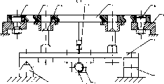
Fig. 1 does not have the structural representation of interfering precision positioning mechanism for multi-position processing system of the present invention.
Among Fig. 1,1 is guide rail, and 2 is screw mandrel, and 3 is nut, and 4 are the retinue platform, and 5 is positioning table, and 6 is locating stud, and 7 is worktable, and 8 is cylinder, and 9 is special setting circle pin, and 10 is abutment sleeve, and 11 is positioning hole.
Fig. 2 is the work schematic representation of multi-position system authority of the present invention.
Among Fig. 2,1 is guide rail, and 2 is screw mandrel, and 3 is nut, and 5 is positioning table, and 6 is locating stud, and 7 is worktable, and 9 is special setting circle pin, and 12 is motor, and 13 is the biserial radial thrust bearing, and 14 is deep groove ball bearing.
Fig. 1 illustrates to cross-section structure for AA among Fig. 2.
Embodiment:
Below in conjunction with accompanying drawing technological scheme of the present invention is further described.
Structure of the present invention as shown in Figure 1, 2.The two ends of retinue platform 4 are placed on respectively on two guide rails 1, and retinue platform 4 can move on guide rail 1.Nut 3 is positioned at the neutral position of retinue platform 4 bottom surfaces, and fixedlys connected with retinue platform 4.Screw mandrel 2 is placed on the centre of two guide rails 1, and parallel with guide rail 1.The two ends of screw mandrel 2 are respectively by biserial radial thrust bearing 13 and deep groove ball bearing 14 location, by motor 12 driven rotary.Screw mandrel 2 constitutes the spiral motion pair with nut 3, when screw mandrel 2 rotates, drives nut 3 so that retinue platform 4 is moved on guide rail 1.Special setting circle pin 9 is fixed on the two ends of retinue platform 4, and the abutment sleeve 10 that matches with special setting circle pin 9 is fixed on the two ends of worktable 7 bottom surfaces.Cylinder 8 connects worktable 7 and retinue platform 4, and Control work platform 7 moving up and down with respect to the retinue platform.Processing locating stud 6 is fixed on the station positioning table 5, matches with positioning hole 11 on the worktable 7.
The multi-position Precision Positioning of worktable 7 as shown in Figure 2.Operative workpiece is positioned and is installed on the worktable 7.In the time of when worktable 7 arrives processing stations along with retinue platform 4 near, worktable and the retinue cylinder 8 between the platform lifts worktable, worktable 7 is from the top of this station positioning table 5 then, advancing to place, concrete position location falls, positioning hole 11 on the worktable matches with locating stud 6 on this positioning table 5, realizes the location of worktable at this station.Subsequent working platform 7 repeats above-mentioned steps and realizes the location along with retinue platform 4 arrives next processing stations along arrow shown in Fig. 2.
Worktable 7 has adopted the design of ladder round column structure with the special setting circle pin 9 of retinue platform 4, and the lower end is the great circle shell of column, and the upper end is the roundlet shell of column.In shifting process, worktable 7 utilizes lower end great circle shell of column to be connected with retinue platform 4 at lower position.Worktable 7 moves by the feed screw nut 3 on the retinue platform 4.Behind the concrete station, under cylinder 8 promoted, worktable 7 retinue platforms 4 was relatively lifted on by a relatively large margin, and worktable 7 breaks away from the big column linkage section that retinue platform 4 is located by connecting, both releasings that are located by connecting.When worktable fell slightly after rise, the location was realized by positioning hole on it 11 and the locating stud 6 on the positioning table 5 in the accurate position of worktable in less falling process.This moment, the big column hole on the worktable 7 was corresponding with the roundlet shell of column of ladder cylinder on the platform 4 of accompanying, the location of worktable 7 and positioning table 5 if with the radial error that is positioned with of worktable 7 and retinue platform 4, then can move freely compensation in the horizontal direction, and the location can not take place.After finishing this station manufacturing procedure, worktable 7 rolls back the great circle shell of column location of retinue platform 4 again, and the roundlet shell of column then plays the effect of guiding location.
Claims (2)
1, a kind of multi-position processing system does not have the interference precision positioning mechanism, it is characterized in that forming composite structure by worktable (7) and retinue platform (4), the two ends of retinue platform (4) are placed on two guide rails (1) respectively and go up also and can move along guide rail (1), feed screw nut (3) is fixed in the middle of retinue platform (4) bottom surface, it is middle and parallel with guide rail (1) that screw mandrel (2) is placed on two guide rails (1), screw mandrel (2) constitutes the spiral motion pair with nut (3), setting circle pin (9) is fixed on the two ends of retinue platform (4), the abutment sleeve (10) that matches with locating stud (9) is fixed on the two ends of worktable (7) bottom surface, cylinder (8) connects worktable (7) and retinue platform (4) and Control work platform (7) moving up and down with respect to retinue platform (4), the two ends of worktable (7) are provided with positioning hole (11), go up the processing locating stud (6) that is provided with positioning table (5) and match.
2, do not have the interference precision positioning mechanism as the said multi-position processing system of claim 1, the setting circle pin (9) on the platform (4) that it is characterized in that accompanying adopts the ladder round column structure, and the lower end is the great circle shell of column, and the upper end is the roundlet shell of column.
Priority Applications (1)
| Application Number | Priority Date | Filing Date | Title |
|---|---|---|---|
| CNB031161553A CN1188245C (en) | 2003-04-03 | 2003-04-03 | Precisively positioning mechanism without interferes in multiposition process system |
Applications Claiming Priority (1)
| Application Number | Priority Date | Filing Date | Title |
|---|---|---|---|
| CNB031161553A CN1188245C (en) | 2003-04-03 | 2003-04-03 | Precisively positioning mechanism without interferes in multiposition process system |
Publications (2)
| Publication Number | Publication Date |
|---|---|
| CN1439484A CN1439484A (en) | 2003-09-03 |
| CN1188245C true CN1188245C (en) | 2005-02-09 |
Family
ID=27797093
Family Applications (1)
| Application Number | Title | Priority Date | Filing Date |
|---|---|---|---|
| CNB031161553A Expired - Fee Related CN1188245C (en) | 2003-04-03 | 2003-04-03 | Precisively positioning mechanism without interferes in multiposition process system |
Country Status (1)
| Country | Link |
|---|---|
| CN (1) | CN1188245C (en) |
Families Citing this family (6)
| Publication number | Priority date | Publication date | Assignee | Title |
|---|---|---|---|---|
| CN103433770B (en) * | 2013-08-30 | 2015-09-16 | 福建工程学院 | Multistation special purpose machine tool coupling positioner |
| CN104209815B (en) * | 2014-09-23 | 2018-02-13 | 淄博长迅环保设备有限公司 | A kind of valve body valve plate multistation Continuous maching lathe |
| CN105798694B (en) * | 2016-05-20 | 2018-01-12 | 大连华恒技研工业有限公司 | Combined type pallet |
| CN106737289A (en) * | 2016-12-26 | 2017-05-31 | 天奇自动化工程股份有限公司 | The positioner of variable precision |
| CN108311726B (en) * | 2018-04-13 | 2024-08-09 | 宁夏青航管业有限公司 | Double-sleeve clamp drilling machine convenient for workpiece storage and turnover |
| CN111922803A (en) * | 2020-07-10 | 2020-11-13 | 苏州广隆富机械设备有限公司 | Horizontal type cylinder machining center and machining method thereof |
-
2003
- 2003-04-03 CN CNB031161553A patent/CN1188245C/en not_active Expired - Fee Related
Also Published As
| Publication number | Publication date |
|---|---|
| CN1439484A (en) | 2003-09-03 |
Similar Documents
| Publication | Publication Date | Title |
|---|---|---|
| CN112917142B (en) | Orthopedic posture-adjusting integrated butt-joint platform | |
| CN101745905B (en) | Multi-degree of freedom adjustable assembling platform used for butt joint of aircraft wings | |
| WO2021047142A1 (en) | Composite laser pipe cutting machine | |
| CN100534701C (en) | Flexible locating cramping apparatus controlled by servo | |
| CN102320210B (en) | Cylindrical engraving machine | |
| CN105171534A (en) | Nine-axis and five-linkage vertical and horizontal combined numerical control machining center | |
| CN206732707U (en) | A kind of composite and flexible manufacturing cell | |
| CN104625884B (en) | Automatic boring device of thin-wall-cylinder shaped spare part | |
| CN111085703A (en) | High-precision rapid hole making equipment and hole making method for metal shell structure | |
| CN1188245C (en) | Precisively positioning mechanism without interferes in multiposition process system | |
| CN113649741A (en) | Corrugated plate automatic welding machine and control system thereof | |
| CN201969908U (en) | Multi-station automatic adjustable multi-spindle drilling machine | |
| CN109158672B (en) | Sliding bearing oil groove machining device and milling machine and method for installing sliding bearing oil groove machining device | |
| CN205218687U (en) | Compound numerical control machining center that crouches is immediately moved to nine quintuplets | |
| CN107962394B (en) | Multifunctional drilling and tapping milling machine and operation method thereof | |
| CN217617836U (en) | End effector for robot drilling | |
| CN116787229A (en) | Multifunctional turning, milling and grinding composite machining center | |
| CN110480421A (en) | A kind of horizontal five-axis robot lathe | |
| CN108907593A (en) | A kind of carrier rocket tank circular seam welding Automated assembly pose_adjuster | |
| CN213570583U (en) | Induction quenching machine tool for machining inner and outer ring channels of gear ring | |
| CN113305590A (en) | Numerical control polar coordinate turning and milling machine | |
| CN203665375U (en) | Workpiece positioning synchronous device of automatic elbow insertion machine | |
| CN207119986U (en) | Modularization end carriage processing unit (plant) | |
| CN200948540Y (en) | Milling propulsion plant moving with work bench | |
| CN110814773A (en) | Combined intelligent turning and grinding integrated cutter and use method |
Legal Events
| Date | Code | Title | Description |
|---|---|---|---|
| C06 | Publication | ||
| PB01 | Publication | ||
| C10 | Entry into substantive examination | ||
| SE01 | Entry into force of request for substantive examination | ||
| C14 | Grant of patent or utility model | ||
| GR01 | Patent grant | ||
| C19 | Lapse of patent right due to non-payment of the annual fee | ||
| CF01 | Termination of patent right due to non-payment of annual fee |