CN1188198C - Separators for liquid suspensions - Google Patents
Separators for liquid suspensions Download PDFInfo
- Publication number
- CN1188198C CN1188198C CNB008157421A CN00815742A CN1188198C CN 1188198 C CN1188198 C CN 1188198C CN B008157421 A CNB008157421 A CN B008157421A CN 00815742 A CN00815742 A CN 00815742A CN 1188198 C CN1188198 C CN 1188198C
- Authority
- CN
- China
- Prior art keywords
- small
- plate
- container
- spiral
- plates
- Prior art date
- Legal status (The legal status is an assumption and is not a legal conclusion. Google has not performed a legal analysis and makes no representation as to the accuracy of the status listed.)
- Expired - Lifetime
Links
Images


Classifications
-
- B—PERFORMING OPERATIONS; TRANSPORTING
- B01—PHYSICAL OR CHEMICAL PROCESSES OR APPARATUS IN GENERAL
- B01D—SEPARATION
- B01D17/00—Separation of liquids, not provided for elsewhere, e.g. by thermal diffusion
- B01D17/02—Separation of non-miscible liquids
-
- C—CHEMISTRY; METALLURGY
- C02—TREATMENT OF WATER, WASTE WATER, SEWAGE, OR SLUDGE
- C02F—TREATMENT OF WATER, WASTE WATER, SEWAGE, OR SLUDGE
- C02F1/00—Treatment of water, waste water, or sewage
- C02F1/38—Treatment of water, waste water, or sewage by centrifugal separation
-
- B—PERFORMING OPERATIONS; TRANSPORTING
- B01—PHYSICAL OR CHEMICAL PROCESSES OR APPARATUS IN GENERAL
- B01D—SEPARATION
- B01D17/00—Separation of liquids, not provided for elsewhere, e.g. by thermal diffusion
- B01D17/02—Separation of non-miscible liquids
- B01D17/0208—Separation of non-miscible liquids by sedimentation
- B01D17/0211—Separation of non-miscible liquids by sedimentation with baffles
-
- B—PERFORMING OPERATIONS; TRANSPORTING
- B01—PHYSICAL OR CHEMICAL PROCESSES OR APPARATUS IN GENERAL
- B01D—SEPARATION
- B01D17/00—Separation of liquids, not provided for elsewhere, e.g. by thermal diffusion
- B01D17/02—Separation of non-miscible liquids
- B01D17/0217—Separation of non-miscible liquids by centrifugal force
-
- B—PERFORMING OPERATIONS; TRANSPORTING
- B01—PHYSICAL OR CHEMICAL PROCESSES OR APPARATUS IN GENERAL
- B01D—SEPARATION
- B01D17/00—Separation of liquids, not provided for elsewhere, e.g. by thermal diffusion
- B01D17/02—Separation of non-miscible liquids
- B01D17/04—Breaking emulsions
- B01D17/045—Breaking emulsions with coalescers
-
- B—PERFORMING OPERATIONS; TRANSPORTING
- B01—PHYSICAL OR CHEMICAL PROCESSES OR APPARATUS IN GENERAL
- B01D—SEPARATION
- B01D21/00—Separation of suspended solid particles from liquids by sedimentation
-
- B—PERFORMING OPERATIONS; TRANSPORTING
- B01—PHYSICAL OR CHEMICAL PROCESSES OR APPARATUS IN GENERAL
- B01D—SEPARATION
- B01D21/00—Separation of suspended solid particles from liquids by sedimentation
- B01D21/0003—Making of sedimentation devices, structural details thereof, e.g. prefabricated parts
-
- B—PERFORMING OPERATIONS; TRANSPORTING
- B01—PHYSICAL OR CHEMICAL PROCESSES OR APPARATUS IN GENERAL
- B01D—SEPARATION
- B01D21/00—Separation of suspended solid particles from liquids by sedimentation
- B01D21/0039—Settling tanks provided with contact surfaces, e.g. baffles, particles
- B01D21/0045—Plurality of essentially parallel plates
-
- B—PERFORMING OPERATIONS; TRANSPORTING
- B01—PHYSICAL OR CHEMICAL PROCESSES OR APPARATUS IN GENERAL
- B01D—SEPARATION
- B01D21/00—Separation of suspended solid particles from liquids by sedimentation
- B01D21/02—Settling tanks with single outlets for the separated liquid
-
- B—PERFORMING OPERATIONS; TRANSPORTING
- B01—PHYSICAL OR CHEMICAL PROCESSES OR APPARATUS IN GENERAL
- B01D—SEPARATION
- B01D21/00—Separation of suspended solid particles from liquids by sedimentation
- B01D21/24—Feed or discharge mechanisms for settling tanks
- B01D21/2405—Feed mechanisms for settling tanks
-
- B—PERFORMING OPERATIONS; TRANSPORTING
- B01—PHYSICAL OR CHEMICAL PROCESSES OR APPARATUS IN GENERAL
- B01D—SEPARATION
- B01D21/00—Separation of suspended solid particles from liquids by sedimentation
- B01D21/26—Separation of sediment aided by centrifugal force or centripetal force
-
- B—PERFORMING OPERATIONS; TRANSPORTING
- B01—PHYSICAL OR CHEMICAL PROCESSES OR APPARATUS IN GENERAL
- B01D—SEPARATION
- B01D21/00—Separation of suspended solid particles from liquids by sedimentation
- B01D21/26—Separation of sediment aided by centrifugal force or centripetal force
- B01D21/265—Separation of sediment aided by centrifugal force or centripetal force by using a vortex inducer or vortex guide, e.g. coil
-
- B—PERFORMING OPERATIONS; TRANSPORTING
- B01—PHYSICAL OR CHEMICAL PROCESSES OR APPARATUS IN GENERAL
- B01D—SEPARATION
- B01D21/00—Separation of suspended solid particles from liquids by sedimentation
- B01D21/0006—Settling tanks provided with means for cleaning and maintenance
-
- B—PERFORMING OPERATIONS; TRANSPORTING
- B01—PHYSICAL OR CHEMICAL PROCESSES OR APPARATUS IN GENERAL
- B01D—SEPARATION
- B01D21/00—Separation of suspended solid particles from liquids by sedimentation
- B01D21/24—Feed or discharge mechanisms for settling tanks
- B01D21/2433—Discharge mechanisms for floating particles
-
- B—PERFORMING OPERATIONS; TRANSPORTING
- B01—PHYSICAL OR CHEMICAL PROCESSES OR APPARATUS IN GENERAL
- B01D—SEPARATION
- B01D21/00—Separation of suspended solid particles from liquids by sedimentation
- B01D21/24—Feed or discharge mechanisms for settling tanks
- B01D21/245—Discharge mechanisms for the sediments
Landscapes
- Chemical & Material Sciences (AREA)
- Chemical Kinetics & Catalysis (AREA)
- Physics & Mathematics (AREA)
- Thermal Sciences (AREA)
- Engineering & Computer Science (AREA)
- Water Supply & Treatment (AREA)
- Mechanical Engineering (AREA)
- Life Sciences & Earth Sciences (AREA)
- Hydrology & Water Resources (AREA)
- Environmental & Geological Engineering (AREA)
- Analytical Chemistry (AREA)
- Organic Chemistry (AREA)
- Centrifugal Separators (AREA)
- Physical Water Treatments (AREA)
- Extraction Or Liquid Replacement (AREA)
- Physical Or Chemical Processes And Apparatus (AREA)
- Separation Of Solids By Using Liquids Or Pneumatic Power (AREA)
- Mixers Of The Rotary Stirring Type (AREA)
- Details Of Rigid Or Semi-Rigid Containers (AREA)
- Degasification And Air Bubble Elimination (AREA)
- Sewage (AREA)
- Feeding, Discharge, Calcimining, Fusing, And Gas-Generation Devices (AREA)
- Heat-Exchange Devices With Radiators And Conduit Assemblies (AREA)
Abstract
Description
本发明涉及一种液体处理设备和构成液体处理设备的方法,具体地但不是专门地涉及一种用于从液体中分离出固体或液体微粒的装置,其中所述装置被布置成可以现场装配。The present invention relates to a liquid treatment apparatus and a method of constituting a liquid treatment apparatus, in particular but not exclusively to an apparatus for separating solid or liquid particles from a liquid, wherein said apparatus is arranged to be assembled on site.
已知的是,EP-A-0666769中提供了一种设备,其中可以用螺旋分离器从液体中分离出固体或液体微粒。螺旋分离器包括多个同轴螺旋板,最好采用多层缠绕的螺旋形状。可以将这些螺旋分离器布置在储液容器中的待处理液体主体中,并且使这些螺旋分离器旋转以使液体沿着多个螺旋流动路径轴向流动。轴向流动的方向依据液体是在液体主体的顶部处还是在其底部处被加到储液容器中的而定。例如,当液体是在液体主体的底部处被加到储液容器中并且是在液体主体的顶部处被排出以便去除比较稠密的固体或液体杂质时,一个或多个分离器被旋转,以便通过分离器引起上升流动。然而,由于螺旋分离器是物理尺寸相当大的单个部件,所以它们的制造、运输和安装都将很困难。It is known from EP-A-0666769 to provide an apparatus in which solid or liquid particles can be separated from a liquid by means of a spiral separator. The spiral separator comprises a plurality of coaxial spiral plates, preferably in the form of a multi-layer wound spiral. The helical separators may be arranged in the body of liquid to be treated in the liquid storage container and rotated to cause the liquid to flow axially along the plurality of helical flow paths. The direction of axial flow depends on whether the liquid is added to the reservoir at the top or bottom of the body of liquid. For example, when liquid is added to the reservoir at the bottom of the body of liquid and is drained at the top of the body of liquid to remove denser solid or liquid Separators cause upward flow. However, because spiral separators are physically large individual components, their manufacture, transportation and installation can be difficult.
本发明的一个目的是提供一种可以由多个较小的部件构成的螺旋分离器,以减少上述的运输和操作问题。It is an object of the present invention to provide a spiral separator which can be constructed from a number of smaller parts so as to reduce the transport and handling problems mentioned above.
根据本发明的第一方面,本发明提供了一种液体处理设备,该设备包括:储液容器,该储液容器限定了一个基本上垂向的圆形截面的流动通道;螺旋分离器,所述螺旋分离器包括一个或多个锥形螺旋板,所述锥形螺旋板限定了在一个或多个板的轴向相对表面之间的至少一个螺旋流动通道,螺旋分离器被同轴地设置在流动通道中,分离器的直径基本上与流动通道的直径相等,螺旋分离器能够绕流动通道的轴线旋转;用于向储液容器供应未经分离的液体的入口装置;以及用于将已处理过的液体从储液容器中排出的出口装置,入口装置和出口装置相对于储液容器被垂直地隔开,这种布置使得入口装置和出口装置之间的液体垂直地流过螺旋分离器的螺旋流动通道,其中分离器的锥形螺旋板包括多个小板,每一个小板的形状为环形扇面,每一个小板具有两个同心弯曲的边缘,其中两个弯曲边缘中的一个稍短的边缘是凹面的而稍长的弯曲边缘是凸面的,并且所述弯曲边缘被相对于所述弯曲边缘径向延伸的前沿和后沿连接,每一个小板还围绕径向轴线弯曲,并且用间隔装置使小板与轴向相邻的小板分隔开;以及According to a first aspect of the present invention, the present invention provides a liquid treatment apparatus comprising: a liquid storage container defining a substantially vertical flow channel of circular cross-section; a spiral separator, the The spiral separator comprises one or more conical spiral plates defining at least one spiral flow channel between axially opposite surfaces of the one or more plates, the spiral separator being coaxially arranged In the flow channel, the diameter of the separator is substantially equal to the diameter of the flow channel, the spiral separator can rotate around the axis of the flow channel; an inlet device for supplying unseparated liquid to the liquid storage container; The outlet device through which the treated liquid is discharged from the liquid storage container, the inlet device and the outlet device are vertically separated with respect to the liquid storage container, this arrangement allows the liquid between the inlet device and the outlet device to flow vertically through the spiral separator The spiral flow channel of the separator, wherein the conical spiral plate of the separator includes a plurality of small plates, each small plate is in the shape of a circular sector, and each small plate has two concentric curved edges, one of the two curved edges is slightly the short edge is concave and the slightly longer curved edge is convex, and said curved edge is connected by leading and trailing edges extending radially relative to said curved edge, each platelet is also curved about a radial axis, and separating the panels from axially adjacent panels by spacers; and
螺旋分离器的每个小板的尺寸能使小板通过螺旋分离器的中央轴向通道。Each platelet of the spiral separator is sized such that the platelet passes through the central axial passage of the spiral separator.
根据本发明的第二方面,本发明披露了一种螺旋分离器,该螺旋分离器包括“板组件”,所述板组件包括锥形螺旋板,锥形螺旋板限定了在板的轴向相对表面之间的螺旋流动通道,螺旋分离器被同轴地设置在液体处理设备的流动通道中,分离器的直径基本上与流动通道的直径相等,螺旋分离器能够绕流动通道的轴线旋转,其中板组件的锥形螺旋板包括多个小板。According to a second aspect of the present invention, the present invention discloses a spiral separator comprising a "plate assembly" comprising conical spiral plates defining axially opposite The spiral flow channel between the surfaces, the spiral separator is coaxially arranged in the flow channel of the liquid treatment device, the diameter of the separator is substantially equal to the diameter of the flow channel, the spiral separator can rotate around the axis of the flow channel, wherein The conical spiral plate of the plate assembly includes a plurality of small plates.
根据本发明的第三方面,本发明披露了一种形状像环形扇面的小板。两个边缘被同心弯曲以使两者中一个稍短的边缘是凹面的而稍长的弯曲边缘是凸面的,并且所述弯曲边缘被一对相对于所述同心边缘径向延伸的发散边缘所连接,板也围绕垂直于同心边缘的板的平面的轴线弯曲。发散边缘构成所述小板的前沿和后沿,当所述小板处于板组件中的适当位置处时,用间隔装置使小板与轴向相邻的小板的上或下表面分隔开。According to a third aspect of the invention, the invention discloses a small plate shaped like a circular sector. The two edges are concentrically curved so that a shorter one of the two is concave and a longer curved edge is convex, and said curved edge is surrounded by a pair of diverging edges extending radially relative to said concentric edge. Connected, the plate is also bent about an axis perpendicular to the plane of the plate at the concentric edges. divergent edges forming leading and trailing edges of said platelets, when said platelets are in place in a plate assembly, spacer means separate a platelet from the upper or lower surface of an axially adjacent platelet .
根据本发明的第三方面的一个实施例,本发明披露了一种形状像环形扇面的小板。两个边缘被同心弯曲以使两者中一个稍短的边缘是凹面的而稍长的弯曲边缘是凸面的,且所述弯曲边缘被一对相对于所述同心边缘径向延伸的发散边缘所连接,板也围绕垂直于同心边缘的板的平面的轴线弯曲。发散边缘构成所述小板的前沿和后沿。该小板的前沿在小板的厚度方向上偏移基本等于小板厚度的距离以便当邻接的小板搭接时可以获得连续平滑的上表面。小板还设置有凸缘部分,所述凸缘部分位于小板中稍短的、凹面的边缘处,并且形成了同心地装有凹面的弯曲边缘的圆柱形弯曲壁。远离小板的凸缘部分的边缘可以被径向地嵌入,并且边缘上有一个或多个被进一步径向嵌入的凹进部分。凸缘和凸缘的径向嵌入部分都具有定位装置,其中所述凸缘起到间隔装置的作用,即当所述小板处于板组件中的适当位置处时,使小板与轴向相邻的小板的上或下表面分隔开,而且所述定位装置还允许轴向相邻的小板这样定位,即,使得在由邻接小板的凸缘构成的中央轴向管与流动通道之间提供流体连通。According to one embodiment of the third aspect of the invention, the invention discloses a small plate shaped like a circular sector. The two edges are concentrically curved so that a shorter one of the two is concave and a longer curved edge is convex, and said curved edge is bounded by a pair of diverging edges extending radially relative to said concentric edge. Connected, the plate is also bent about an axis perpendicular to the plane of the plate at the concentric edges. Diverging edges constitute the leading and trailing edges of the platelets. The leading edge of the platelets is offset in the thickness direction of the platelets by a distance substantially equal to the thickness of the platelets so that a continuous smooth upper surface is obtained when adjacent platelets overlap. The small plate is also provided with a flange portion located at the slightly shorter, concave edge of the small plate and forming a cylindrically curved wall concentrically fitted with the concave curved edge. The edge of the flange portion remote from the plate may be radially inset and have one or more recessed portions further radially inset on the edge. Both the flange and the radially embedded portion of the flange have positioning means, wherein the flange acts as a spacer, i.e. keeps the small plate axially adjacent when the small plate is in place in the plate assembly. The upper or lower surface of the small plate is separated, and the positioning device also allows the axially adjacent small plate to be positioned such that between the central axial tube formed by the flange of the adjacent small plate and the flow channel provide fluid communication.
根据本发明的第四方面,本发明披露了一种用在液体处理设备中的螺旋分离器的构建方法,其特征在于,在第一构建步骤中,将多个小板连接在环形驱动圈上以形成第一小板圈,在其后的构建步骤中,小板从第一圈小板的中央开口中穿过并连接到构成第一小板圈的小板上。According to the fourth aspect of the present invention, the present invention discloses a construction method of a spiral separator used in liquid treatment equipment, characterized in that, in the first construction step, a plurality of small plates are connected to the annular driving ring In order to form the first circle of small plates, in subsequent building steps, the small plates pass through the central opening of the first circle of small plates and are connected to the small plates constituting the first circle of small plates.
根据本发明,提供了一种构建液体处理设备的方法,该方法包括以下步骤:According to the present invention there is provided a method of constructing a liquid handling plant, the method comprising the steps of:
提供具有开口上端的容器;providing a container with an open upper end;
提供与所述容器流体连通的入口和出口装置;providing inlet and outlet means in fluid communication with the container;
在容器的所述开口端提供桥接装置并且在所述桥接装置上支撑水平的环形驱动圈;providing bridging means at said open end of the container and supporting a horizontal annular drive ring on said bridging means;
为容器提供流槽;Provide launders for containers;
将所述流槽连接到所述出口装置以便使流槽与出口流体连通;connecting the launder to the outlet device so as to place the launder in fluid communication with the outlet;
在容器内装配包括多个小板的板组件,装配步骤包括以下步骤:Assembling a board assembly including a plurality of small boards within a container, the assembly steps include the following steps:
将小板从环形驱动圈上悬吊下来以形成第一小板圈;suspending the small plate from the annular drive ring to form the first small plate ring;
使小板从由第一小板圈形成的中央轴向通道中穿过;passing the small plate through the central axial channel formed by the first small plate circle;
将小板连接到第一圈小板的下侧以形成包括至少一个锥形螺旋板的板组件。A small plate is attached to the underside of the first ring of small plates to form a plate assembly comprising at least one conical spiral plate.
在该方法中,可将所述容器设置在地平面以下。In this method, the container may be positioned below ground level.
根据本发明,还提供了一种构建液体处理设备的方法,该方法包括以下步骤:According to the present invention, there is also provided a method of constructing a liquid treatment device, the method comprising the steps of:
提供具有开口上端的容器,所述容器的下部形成有入口,其中所述入口的尺寸使小板可以通过;providing a container having an open upper end, the lower portion of which is formed with an inlet, wherein the inlet is sized to allow passage of the small plates;
提供与所述容器流体连通的入口和出口装置;providing inlet and outlet means in fluid communication with the container;
在容器的开口端提供桥接装置并且在所述桥接装置上支撑水平的环形驱动圈;providing bridging means at the open end of the container and supporting a horizontal annular drive ring on said bridging means;
为容器提供流槽;Provide launders for containers;
将所述流槽连接到所述出口装置以便使流槽与出口流体连通;connecting the launder to the outlet device so as to place the launder in fluid communication with the outlet;
在容器内装配包括多个小板的板组件,装配步骤包括以下步骤:Assembling a board assembly including a plurality of small boards within a container, the assembly steps include the following steps:
将小板从容器下部形成的入口中穿过;Pass the small plate through the inlet formed in the lower part of the container;
将小板从环形驱动圈上悬吊下来以形成第一小板圈;suspending the small plate from the annular drive ring to form the first small plate ring;
将小板连接到第一圈小板的下侧以形成包括至少一个锥形螺旋板的板组件。用所述小板构建螺旋分离器的优点是,首先,分离器可以就地装配,这样在运输和安装过程中无需重型吊装设备。此外,由于分离器是由单个小板组合而成的而不是一个整体部件,因此,分离器的任何故障或损坏都能够通过更换单个有故障的或损坏的小板来校正。A small plate is attached to the underside of the first ring of small plates to form a plate assembly comprising at least one conical spiral plate. The advantages of constructing a spiral separator from said small plates are, firstly, that the separator can be assembled in situ so that no heavy lifting equipment is required during transport and installation. Furthermore, since the separator is assembled from individual platelets rather than a unitary unit, any failure or damage to the separator can be corrected by replacing a single faulty or damaged platelet.
小板的尺寸可使包含板组件的螺旋分离器的构建操作能够在板组件将在其中运转的流动通道内执行。The dimensions of the small plates may enable construction operations of the spiral separator comprising the plate assembly to be performed within the flow channel in which the plate assembly will operate.
在优选实施例中,分离器包括多个由独立小板形成的锥形螺旋板,这些锥形螺旋板采用多层缠绕的螺旋形状以形成板组件。In a preferred embodiment, the separator comprises a plurality of conical helical plates formed from individual small plates which take the shape of a helix wound in multiple layers to form a plate assembly.
在优选实施例中,小板在从其前沿到其后沿的方向上的横截面逐渐变窄,或者反之亦然,这样不会使每一个小板的搭接的边缘在连接处变厚。In a preferred embodiment, the panels taper in cross-section from their leading edge to their trailing edge, or vice versa, so as not to thicken the overlapping edges of each panel at the junction.
在优选实施例的另一个方面,可以将螺旋分离器安装在一个现有的任何非圆形截面的储液容器中。该现有储液容器可以具有任何的平面形状,并且可以容纳内部衬块,因此可以提供圆形截面的流动通道。In another aspect of the preferred embodiment, the spiral separator can be installed in an existing liquid storage vessel of any non-circular cross-section. The existing reservoir can have any planar shape and can accommodate an internal pad, thus providing a flow channel of circular cross-section.
能够将螺旋分离器布置在一个现有储液容器中的一个优点是,因为不需要涉及储液容器的构建的花费,所以能够降低总成本。One advantage of being able to place the spiral separator in an existing liquid storage vessel is that the overall cost can be reduced since no expense is required concerning the construction of the liquid storage vessel.
在另一个实施例中,一种构建螺旋分离器的方法包括,在工作位置处将多个小板安装到环形驱动圈上以形成小板圈,所述环形驱动圈又被安装到提升装置上,并且在完成该小板圈的基础上,提起环形驱动圈,这样就能够将另一小板圈增加到板组件中而不用移动工作位置。In another embodiment, a method of constructing a spiral separator includes, at a working position, mounting a plurality of small plates to an annular drive ring to form a ring of small plates, the annular drive ring being mounted to a lifting device , and on the basis of completing the small plate ring, lift the annular driving ring, so that another small plate ring can be added to the plate assembly without moving the working position.
与这种构建方法相关的一个优点是,总是在同一水平面(例如,储液容器或容纳装置的底部)上进行构建。在某些情况中,当操作进行时,与移动工作台相比,移动部分完成的板组件是更方便的。An advantage associated with this method of construction is that the construction is always performed on the same level (eg the bottom of the reservoir or containment). In some cases, it may be more convenient to move a partially completed panel assembly than to move a work table while operations are in progress.
仅以举例的方法和参照以下附图对本发明的实施例进行描述,其中:Embodiments of the invention are described, by way of example only, with reference to the following drawings, in which:
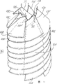
图1是表示多个由小板构成的锥形螺旋板的示意图,并且这些锥形螺旋板设置成多层缠绕的螺旋形状以形成板组件;Figure 1 is a schematic view showing a plurality of conical spiral plates made of small plates, and these conical spiral plates are arranged in a spiral shape wound in multiple layers to form a plate assembly;
图2示出了一个单独的小板;Figure 2 shows a single small board;
图3示出了图2中所示的两个小板是如何安装在一起的;Figure 3 shows how the two small boards shown in Figure 2 fit together;
图4示出了在另外的实施例中的多个小板;Figure 4 shows a plurality of small plates in a further embodiment;
图5是表示由如图4中所示的多个小板构成的一个锥形螺旋板的示意图;Figure 5 is a schematic diagram representing a conical spiral plate made of a plurality of small plates as shown in Figure 4;
图6示出了容纳装置在第一方法中构成板组件的最初阶段的侧视截面图;Figure 6 shows a side cross-sectional view of the initial stage of the container forming the plate assembly in the first method;
图7示出了容纳装置在已经完成板组件的构造时的侧视截面图;Figure 7 shows a side sectional view of the receiving device when the construction of the plate assembly has been completed;
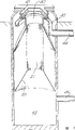
图8示出了完成的液体处理设备的侧视截面图;Figure 8 shows a side cross-sectional view of the completed liquid handling device;
图9示出了容纳装置在第二方法中构成板组件的最初阶段的侧视截面图;Figure 9 shows a side cross-sectional view of the initial stage of the container forming the plate assembly in the second method;
图10示出了容纳装置在部分完成板组件的构造(第二方法)时的侧视截面图;Figure 10 shows a side sectional view of the containment device when the construction of the panel assembly is partially completed (second method);
图11示出了容纳装置在已经完成板组件的构造(第二方法)时并且在环形驱动圈被固定就位以前的侧视截面图;Figure 11 shows a side sectional view of the receiving device when construction of the plate assembly has been completed (second method) and before the annular drive ring is fixed in place;
图12示出了用在装配板组件的第三方法中的容纳装置的透视图。Figure 12 shows a perspective view of the receiving device used in the third method of assembling the panel assembly.
在如图1中所示的完成的板组件20中,小板10A至10F构成第一小板圈。在板组件20的中心处具有开口21,所述开口21轴向地贯穿板组件20的整个长度。当已经将板组件20安装在处理设备中时,然后将中央釜馏管46(未示出)放置在中心开口21中。小板10G、10H的间隔装置11G、11H与小板10A、10B的间隔装置11A、11B在轴向上对齐。将间隔装置11G、11H固定在与小板10A、10B上侧的间隔装置11A、11B的位置相对应的小板10A、10B的下侧位置上。In the completed
图2中所示的小板10是形成锥形螺旋板所需的多个小板中的一个。小板10的形状像环形扇面。两个边缘(根部14、端部15)被同心弯曲以使根部14是凹面的而端部15是凸面的,弯曲线围绕垂直于板平面的轴线,板也围绕板平面中垂直于弯曲的边缘的一个轴线弯曲,而发散边缘相对于弯曲线径向延伸。在前沿12处有薄部16。由薄部16和小板10的主体所构成的阶160相对于弯曲线径向地延伸,并且该阶160平行于前沿12。在小板10的后沿13处有另一个薄部17。由薄部17和小板10的主体所构成的阶170径向地延伸,并且该阶170平行于后沿13。是这样安排薄部16和17的,即,在板组件20中可利用相邻小板10的相应薄部16、17形成搭接的连接部分。在前沿12处的薄部16上设有多个口18A,所述口18A位于小板的前沿和阶160之间的中间位置,所述阶160位于变薄部分16与小板10的主体之间,而且所述多个口18A在径向上以等距离布置。在后沿13处的薄部17上同样具有多个口19A,并且这些口19A以和前述的口18A同样的方法布置。该小板上还具有放置于靠近根部14的一个拐角中的间隔装置11。该间隔装置11的用途是将该小板10与轴向相邻的小板分隔开。The
图3示出了两个相邻的小板10A、10H,其中相同的附图标记表示相同部件,带有后缀A的是一个小板的部件,而带有后缀H的是另一个小板的相同部件。可以看出,小板10H的前沿12H处的多个口18H与小板10A的后沿13A处的多个口19A相对应。可以使用固定装置诸如铆钉、螺丝、榫钉、螺栓等来连接相邻的小板。Figure 3 shows two adjacent small plates 10A, 10H, wherein the same reference numerals indicate the same parts, with the suffix A being part of one small plate and the suffix H being the other small plate. same parts. It can be seen that the plurality of ports 18H at the leading edge 12H of the platelet 10H corresponds to the plurality of ports 19A at the trailing edge 13A of the platelet 10A. Adjacent small panels may be connected using fastening means such as rivets, screws, dowels, bolts, and the like.
从图中可以看出,小板10A的阶与相邻的小板10H的前沿12H邻接,而且小板10A的后沿13H也与相邻小板10H的阶邻接以使薄部16H、17A相互配合以形成搭接的连接部分。As can be seen from the figure, the step of the small plate 10A is adjacent to the leading edge 12H of the adjacent small plate 10H, and the rear edge 13H of the small plate 10A is also adjacent to the step of the adjacent small plate 10H so that the thin portions 16H, 17A are mutually adjacent. Mates to form overlapping joints.
图4中示出了第二种类型的小板22。在这里,将使用后缀A、B、C、D来标识各个小板22A、22B、22C、22D的部件。然而,为了保持清晰,在图中只给各个小板加了后缀A、B、C、D。A second type of small plate 22 is shown in FIG. 4 . Here, the suffixes A, B, C, D will be used to identify the components of the respective small plates 22A, 22B, 22C, 22D. However, to maintain clarity, only the suffixes A, B, C, D have been added to the individual panels in the figures.
各个小板22A、22B、22C、22D的形状都像环形扇面,并且是相同的。两个边缘23、34被同心弯曲以使两者中一个稍短的边缘23是凹面的而稍长的弯曲边缘24是凸面的,并且所述边缘被一对相对于同心边缘23、24径向延伸的发散边缘25、26连接。发散边缘25、26构成所述小板22的前沿25和后沿26。该小板的前沿25具有在小板的厚度方向上以基本等于小板厚度的距离偏移的偏移部分270,以便当邻接的小板22A、22B或22C、22D搭按时可以获得连续平滑的上表面。后沿26和前沿25中的偏移部分270形成有多个口272、271。在径向上以等距离布置这些口272、271并使邻接的小板22A、22B或22C、22D固定在一起。可以看到,当将邻接的小板(例如22A、22B)固定在一起时,前沿25A中的偏移部分270A上的口271A与后沿26B上的口272B相对应。在上面所述的一个可替换的形式中,该小板22的后沿26也可以在小板的厚度方向上被偏移以便当邻接的小板(例如22A、22B)搭接时可以获得连续平滑的上表面。The individual plates 22A, 22B, 22C, 22D are shaped like circular sectors and are identical. The two edges 23, 34 are concentrically curved so that one of the slightly shorter edges 23 is concave and the slightly longer curved edge 24 is convex, and said edges are curved radially relative to the concentric edges 23, 24. Extended divergent edges 25, 26 connect. Divergent edges 25 , 26 form the leading 25 and trailing 26 edges of said small plate 22 . The leading edge 25 of the platelet has an offset portion 270 offset in the thickness direction of the platelet by a distance substantially equal to the thickness of the platelet, so that a continuous smooth finish can be obtained when the adjacent platelets 22A, 22B or 22C, 22D are lapped. upper surface. The offset portion 270 in the trailing edge 26 and leading edge 25 is formed with a plurality of ports 272,271. These ports 272, 271 are arranged at equal distances in the radial direction and hold adjacent small plates 22A, 22B or 22C, 22D together. It can be seen that the opening 271A on the offset portion 270A in the leading edge 25A corresponds to the opening 272B on the trailing edge 26B when adjoining small plates (eg 22A, 22B) are secured together. In an alternative form to that described above, the trailing edge 26 of the panel 22 may also be offset in the thickness direction of the panel so as to obtain continuity when adjacent panels (eg 22A, 22B) overlap. Smooth upper surface.
小板22还具有凸缘部分28,所述凸缘部分28位于小板22的稍短的、凹面的边缘23处,并且形成了同心地装有凹面的弯曲边缘23的圆柱形弯曲壁。凸缘部分28也可以在与图示方向相反的方向上延伸,或可以这样设置,即,使其从凹面的弯曲边缘23处在轴向上向两边延伸。远离小板的凸缘部分28的边缘29可以被径向地嵌入,并且边缘29上有一个或多个被进一步径向嵌入的凹进部分30。在凸缘28和凸缘的径向嵌入部分29之间形成了阶31。凸缘28和凸缘的径向嵌入部分29具有在前沿25处径向地向内偏移的部分37、38,而且所述部分37、38是小板22的前沿25中的偏移部分270的延续部分。凸缘的径向嵌入部分29上形成有多个口。在凸缘的径向嵌入部分29的后沿处形成有一个口32,在凸缘的径向嵌入部分29的部分38内形成有一个口33。在两个邻接的小板(例如22A、22B)中,口32B与口33A对应。在凸缘的径向嵌入部分29上还有更多的口34,稍后将描述这些口34的用途。凸缘28上形成有多个口36,其中有个特殊口35执行一种也将稍后进行描述的功能。The small plate 22 also has a flange portion 28 which is located at the slightly shorter, concave edge 23 of the small plate 22 and forms a cylindrical curved wall which concentrically fits the concave curved edge 23 . The flange portion 28 may also extend in the opposite direction to that shown, or may be arranged so that it extends axially on both sides from the concave curved edge 23 . The edge 29 of the flange portion 28 remote from the plate may be radially inset, and have one or more recessed portions 30 further radially inset on the edge 29 . A step 31 is formed between the flange 28 and the radially embedded portion 29 of the flange. The flange 28 and the radially embedded portion 29 of the flange have portions 37 , 38 offset radially inwardly at the leading edge 25 and said portions 37 , 38 are offset portions 270 in the leading edge 25 of the platelet 22 continuation of the . A plurality of openings are formed in the radially embedded portion 29 of the flange. A port 32 is formed at the rear edge of the radially inset portion 29 of the flange and a port 33 is formed in a portion 38 of the radially inset portion 29 of the flange. In two adjacent small plates (eg 22A, 22B), port 32B corresponds to port 33A. There are further ports 34 on the radially embedded portion 29 of the flange, the purpose of which will be described later. Flange 28 is formed with a plurality of ports 36, of which a special port 35 performs a function which will also be described later.
在如图4所示的一种排列中,两个邻接小板22A、22B与另外两个邻接小板22C、22D相互配合,所述另外两个邻接小板22C、22D与小板22A、22B轴向邻接。然而可以看出,这些小板22不是笔直地轴向对准,并且邻接小板22A、22B相对于另外两个邻接小板22C、22D周向偏移。凸缘28A、28B与小板22A、22B相交的凹面边缘23A、23B处于轴向邻接的小板22C、22D的阶31C、31D上。可以看出,凸缘28B中的多个口36B与凸缘的径向嵌入部分29D上的口34C、D相对应,而且特别是凸缘28B的特殊口35B与轴向邻接的小板22C、22D的口32D和33C相对应。这样当完成板组件20时,小板22的凸缘28形成贯穿板组件20的中心的中央轴向管,而且所述凹进部分30提供了用于固体微粒和液体流动的装置。In one arrangement as shown in FIG. 4 , two adjacent plates 22A, 22B cooperate with two other adjacent plates 22C, 22D which cooperate with the plates 22A, 22B. Axially adjacent. However, it can be seen that these small plates 22 are not straight axially aligned and that the adjacent small plates 22A, 22B are circumferentially offset relative to the other two adjacent small plates 22C, 22D. The concave edges 23A, 23B where the flanges 28A, 28B meet the platelets 22A, 22B are on steps 31C, 31D of the axially adjacent platelets 22C, 22D. It can be seen that the plurality of openings 36B in the flange 28B correspond to the openings 34C, D on the radially embedded portion 29D of the flange, and in particular the special opening 35B of the flange 28B corresponds to the axially adjacent small plate 22C, D. Ports 32D and 33C of 22D correspond. Thus when the
如图5中所示,一系列连接在一起的邻接小板22将构成锥形螺旋板39。锥形螺旋板39还具有前导小板220和拖尾小板221,最好前导小板220和拖尾小板221都具有凸缘28、凸缘的径向嵌入部分29、和凹进部分30。As shown in FIG. 5 , a series of adjacent small plates 22 connected together will form a tapered spiral plate 39 . The tapered spiral plate 39 also has a leading small plate 220 and a trailing small plate 221, preferably the leading small plate 220 and the trailing small plate 221 all have a flange 28, a radially embedded portion 29 of the flange, and a recessed portion 30 .
现在将描述三个可替换的构造方法,而且对于小板10和可替换的小板22来说该描述都适用,然而,为了保持清晰,在以下的描述中将只使用附图标记10。Three alternative methods of construction will now be described, and this description applies to both the
在图6中示出了就地装配的最初阶段。即将形成第一小板圈的这组小板10A到10F被用螺栓固定到环形驱动圈40的周围,所述环形驱动圈40又从容纳装置42的顶部处的桥41上被悬吊下来。在构建的最初阶段中,小板10从环形驱动圈40的中央穿过。有多种执行该部分构建阶段的方法。将小板10穿过环形驱动圈40的中央,然后将其安装到环形驱动圈40的周围。直到完成了板组件20的构建才开始执行该过程。或者,多个小板10穿过环形驱动圈40的中央并被存储在容纳装置42的底部处。然后一次一个地将这些小板10从容纳装置42的底部处提升,接着将其安装到环形驱动圈40的周围。重复执行该过程直到完成板组件20。另一个选择是,使完成板组件20所需的整个小板组10从环形驱动圈40的中央穿过并被存储在容纳装置42的底部处。如上所述,然后一次一个地将这些小板10从容纳装置42的底部处提升,接着将其安装到环形驱动圈40的周围。The initial stages of in-situ assembly are shown in FIG. 6 . The set of small plates 10A to 10F that will form the first small plate ring is bolted around an
位于容纳装置42的顶部附近的是流槽43,所述流槽43被安装在容纳装置42的壁上并且环绕容纳装置42的周边形成一个完整回路。流槽43与出口44连接,所述出口44在完成的设备内将从容纳装置中排出已处理过的液体。流槽43位于这样一个水平面上,即,略低于完全完成的设备中的液面水平,这样已处理过的液体可以溢流到流槽43中并通过出口44排出。在图中还示出了一个入口45,未经处理的液体将通过该入口45进入到容纳装置42中。图中未示出的驱动装置被连接到环形驱动圈上。在图中所示的这个构建阶段中,因为小板没有可以自承重的内在刚性,所以小板需要被支撑直到已将几个小板连接在一起。这意味着在2或3个完成的小板圈被安装定位以前一直需要这种支撑。被加入到较高的小板的下侧的小板10具有穿过每个完成的小板圈的中心处的开口21的入口。Located near the top of the
图7示出了完成的板组件20。如果,在任何时候,该板组件20需要更换一个小板,那么通过从底部拆开该板组件20就能够更换。这使得在必须更换小板时无需将该板组件从容纳装置42中拆卸下来。FIG. 7 shows the completed
在图8中所示的完成的液体处理设备中,加入一个中央蒸馏管46,该中央蒸馏管46位于完成的小板圈20的中央开口21中。该中央蒸馏管46具有入口管45和污水泵49。如图所示,中央蒸馏管46由支柱47支撑。图8中的布置示出了用于淤渣的中心井50,该中心井50具有可浸入水中的排泥泵51。污水泵49也可是个可浸入水中的泵。这样可以将污水泵49的入口设置在最高处以便从液体表面52去除浮渣。箭头5C、5L分别表示在该具体实施例中浮渣和淤渣的流动方向。箭头U表示未经处理的液体的流动方向。In the completed liquid handling apparatus shown in FIG. 8 , a central distillation tube 46 is added which is located in the
现在将描述第二个构建方法,对于与前述的附图中一致的部件使用相同的附图标记。A second method of construction will now be described, using the same reference numerals for parts consistent with those in the preceding figures.
图9中示出了安装在环形驱动圈40上的形成板组件20的第一小板圈的一组小板10。环形驱动圈40也与提升装置53连接以便当需要时可以将整个组件提升或降低。可以看出,在这种构建方法中,在容纳装置42的底部进行操作。A set of
如在前面的构建方法中一样,也有可供选择的执行板组件25构建阶段的方法。As in the previous construction methods, there are alternative methods of performing the board assembly 25 construction phase.
将小板10穿过环形驱动圈40的中央然后将其安装到环形驱动圈40的周围。重复该过程直到正在构建的小板圈完成。将环形驱动圈40提升足够高,使得在下一个小板圈的构建中可以重复同样的过程。或者,将足够形成一个完成的小板圈的多个小板穿过环形驱动圈40的中央并将它们存储在容纳装置42的底部处。然后一次一个地将这些小板10从容纳装置42的底部处提升,接着将其安装到环形驱动圈40的周围。然后将环形驱动圈40提升足够高,使得可以构建下一个小板圈。然后重复该过程直到完成板组件20。还有一种涉及上述提升环形驱动圈40的选择,即,可以一次实现两个或更多个小板圈的方式进行构建。The
图10示出了图9中的布置,其中已经将许多连续的小板圈添加到板组件20上。已经用提升装置53将整个组件提起来,以使得可以在同样的水平面上进行构建。FIG. 10 shows the arrangement of FIG. 9 where a number of successive small plate circles have been added to the
图11示出了接近完成阶段的构建阶段。已经完成了板组件20,环形驱动圈将被安装到桥(未示出)上。液体处理设备的最终状态是图8中所示的状态。Figure 11 shows the build phase nearing completion. Having completed the
图12示出了本发明的一个实施例,其中容纳装置42基本上位于地平面上。容纳装置42具有位于容纳装置42下端附近的入口55。入口55的尺寸可使小板在构建阶段过程中能够穿过该入口55。该实施例中的构建方法与上面提及的关于图9、10和11的第二个构建方法相似。然而在该第三个方法中,小板不再从环形驱动圈(未示出)的中央穿过,而是从入口55穿过。Figure 12 shows an embodiment of the invention in which the receiving means 42 are located substantially at ground level. The
一旦完成了板组件的构建,就将入口盖板54安在入口55上,因此就形成了流体严密密封。Once the plate assembly is constructed, the inlet cover plate 54 is fitted over the inlet 55, thus forming a fluid tight seal.
在如图12中所示的优选实施例中,入口盖板54还具有一个员工入口装置56,该员工入口装置56允许维修人员无需移开入口盖板54就能够进入容纳装置中,因为对于一个人来说不借助于提升装置而移开入口盖板54是很困难的。用铰接装置将员工入口装置56连接到入口盖板54上,而且当员工入口装置56被关闭时,员工入口装置56与所述入口盖板54形成了流体严密密封。In the preferred embodiment shown in Figure 12, the access panel 54 also has an employee access device 56 that allows maintenance personnel to enter the receptacle without removing the access panel 54, because for a It is difficult for a person to remove the access panel 54 without the aid of a lifting device. The staff access device 56 is hingedly attached to the access panel 54 and forms a fluid tight seal with said access panel 54 when the staff access device 56 is closed.
Claims (19)
Applications Claiming Priority (2)
| Application Number | Priority Date | Filing Date | Title |
|---|---|---|---|
| GB9922472A GB2354466B (en) | 1999-09-22 | 1999-09-22 | Liquid treatment installation and methods of construction thereof |
| GB9922472.7 | 1999-09-22 |
Publications (2)
| Publication Number | Publication Date |
|---|---|
| CN1390151A CN1390151A (en) | 2003-01-08 |
| CN1188198C true CN1188198C (en) | 2005-02-09 |
Family
ID=10861424
Family Applications (1)
| Application Number | Title | Priority Date | Filing Date |
|---|---|---|---|
| CNB008157421A Expired - Lifetime CN1188198C (en) | 1999-09-22 | 2000-09-19 | Separators for liquid suspensions |
Country Status (21)
| Country | Link |
|---|---|
| US (1) | US6660162B1 (en) |
| EP (1) | EP1250182B1 (en) |
| JP (1) | JP4691634B2 (en) |
| KR (1) | KR100671987B1 (en) |
| CN (1) | CN1188198C (en) |
| AR (1) | AR027862A1 (en) |
| AT (1) | ATE295214T1 (en) |
| AU (1) | AU766549B2 (en) |
| CA (1) | CA2385382A1 (en) |
| DE (1) | DE60020168T2 (en) |
| DK (1) | DK1250182T3 (en) |
| EG (1) | EG22417A (en) |
| ES (1) | ES2240154T3 (en) |
| GB (1) | GB2354466B (en) |
| MX (1) | MXPA02003070A (en) |
| MY (1) | MY127431A (en) |
| PE (1) | PE20010465A1 (en) |
| PT (1) | PT1250182E (en) |
| TW (1) | TW466138B (en) |
| WO (1) | WO2001021273A1 (en) |
| ZA (1) | ZA200202084B (en) |
Families Citing this family (15)
| Publication number | Priority date | Publication date | Assignee | Title |
|---|---|---|---|---|
| CN100363080C (en) * | 2005-05-20 | 2008-01-23 | 清华大学 | A device for separating suspended solids in water |
| JP2010017620A (en) * | 2008-07-09 | 2010-01-28 | Tech Corporation:Kk | High-speed coagulation sedimentation apparatus and polluted water purifying method |
| NL1037680C2 (en) * | 2010-02-03 | 2011-08-04 | Wavin Bv | Inspection chamber with filter. |
| IT1404151B1 (en) * | 2010-12-29 | 2013-11-15 | Eni Spa | SEPARATION APPARATUS BY COALESCENCE OF A MIXTURE INCLUDING TWO FLUID PHASES BETWEEN THEM IMMERSIBLE AND DIFFERENT SPECIFIC DENSITY |
| CN102284201A (en) * | 2011-06-09 | 2011-12-21 | 重庆科技学院 | Spiral adjustable slant board |
| CN102228759B (en) * | 2011-06-26 | 2013-03-13 | 韦志锋 | Sewage filter |
| CN102423549B (en) * | 2011-08-02 | 2013-12-18 | 中国科学院力学研究所 | Dewatering apparatus and oil-water cyclone separator of pipe type distributor oil-water separator |
| FR2995932B1 (en) * | 2012-09-21 | 2014-10-31 | Nymphea Environnement | METHOD AND APPARATUS FOR COLLECTING A LIGHT SUBMARINE FLUID SUCH AS FRESHWATER OR HYDROCARBONS |
| CN103894000A (en) * | 2012-12-28 | 2014-07-02 | 赫菲斯热处理系统江苏有限公司 | Oil-water separation device |
| GB2531804B (en) * | 2014-10-31 | 2019-08-21 | Plantwork Systems Ltd | Separator and separation apparatus |
| CN104879851A (en) * | 2015-06-06 | 2015-09-02 | 广东伟照业光电节能有限公司 | Air purifier with sterilization function |
| CN104986864B (en) * | 2015-07-09 | 2017-01-25 | 清华大学深圳研究生院 | Bacterial-algal symbiotic reactor |
| GB2565859B (en) | 2017-08-22 | 2022-05-18 | Hydro Int Ltd | A tray unit for a wastewater treatment device and a method of assembling a tray assembly for a wastewater treatment device |
| NO344801B1 (en) * | 2019-09-06 | 2020-05-04 | Stauper Offshore As | A separation apparatus with insert |
| JP7810624B2 (en) * | 2022-09-21 | 2026-02-03 | 三菱化工機株式会社 | High-speed settling device and method for manufacturing the same |
Family Cites Families (14)
| Publication number | Priority date | Publication date | Assignee | Title |
|---|---|---|---|---|
| US2300129A (en) * | 1940-11-04 | 1942-10-27 | Mccurdy Howard | Helical flow separator |
| US3893914A (en) * | 1973-04-05 | 1975-07-08 | Roy A Bobo | Cyclone centrifuge apparatus |
| JPS5255057A (en) * | 1975-10-31 | 1977-05-06 | Naoshi Honda | Vertical type thickner |
| JPS52157580U (en) * | 1976-05-26 | 1977-11-30 | ||
| DE3122263A1 (en) * | 1981-06-04 | 1982-12-23 | Bayer Ag, 5090 Leverkusen | FUNGICIDES FOR MATERIAL PROTECTION |
| JPS631605U (en) * | 1986-06-24 | 1988-01-07 | ||
| FR2663238B1 (en) * | 1990-06-18 | 1992-09-18 | Inst Francais Du Petrole | METHOD AND DEVICE FOR SEPARATING BETWEEN A CONTINUOUS FLUID PHASE AND A DISPERSED PHASE, AND APPLICATION. |
| GB9106574D0 (en) * | 1991-03-27 | 1991-05-15 | Bagghley Jack | Improvements in or relating to material treatment apparatus |
| JPH07121391B2 (en) * | 1991-08-23 | 1995-12-25 | 忠助 浦田 | Fluid separation device |
| RU2091177C1 (en) * | 1992-03-09 | 1997-09-27 | Ленинградский филиал Совместного советско-американо-польского предприятия "Анкор" | Device for cleaning waste water and other liquids |
| GB9313589D0 (en) * | 1993-07-01 | 1993-08-18 | Southern Water Services Ltd | Separating liquid suspensions |
| AUPM714794A0 (en) * | 1994-07-29 | 1994-08-18 | International Fluid Separation Pty Limited | Separation apparatus and method |
| RU2066243C1 (en) * | 1994-11-17 | 1996-09-10 | Институт проблем прикладной экологии и природопользования | Termohydrocyclone |
| AUPP924799A0 (en) * | 1999-03-17 | 1999-04-15 | Geo2 Limited | Improved separator and process |
-
1999
- 1999-09-22 MX MXPA02003070A patent/MXPA02003070A/en active IP Right Grant
- 1999-09-22 GB GB9922472A patent/GB2354466B/en not_active Expired - Fee Related
-
2000
- 2000-09-14 MY MYPI20004264 patent/MY127431A/en unknown
- 2000-09-19 KR KR1020027003799A patent/KR100671987B1/en not_active Expired - Lifetime
- 2000-09-19 JP JP2001524694A patent/JP4691634B2/en not_active Expired - Lifetime
- 2000-09-19 DK DK00960845T patent/DK1250182T3/en active
- 2000-09-19 CN CNB008157421A patent/CN1188198C/en not_active Expired - Lifetime
- 2000-09-19 CA CA002385382A patent/CA2385382A1/en not_active Abandoned
- 2000-09-19 AT AT00960845T patent/ATE295214T1/en active
- 2000-09-19 WO PCT/GB2000/003587 patent/WO2001021273A1/en not_active Ceased
- 2000-09-19 PT PT00960845T patent/PT1250182E/en unknown
- 2000-09-19 US US10/088,923 patent/US6660162B1/en not_active Expired - Fee Related
- 2000-09-19 AU AU73014/00A patent/AU766549B2/en not_active Expired
- 2000-09-19 EP EP00960845A patent/EP1250182B1/en not_active Expired - Lifetime
- 2000-09-19 ES ES00960845T patent/ES2240154T3/en not_active Expired - Lifetime
- 2000-09-19 DE DE60020168T patent/DE60020168T2/en not_active Expired - Lifetime
- 2000-09-19 PE PE2000000970A patent/PE20010465A1/en not_active Application Discontinuation
- 2000-09-20 EG EG20001209A patent/EG22417A/en active
- 2000-09-22 AR ARP000104996A patent/AR027862A1/en active IP Right Grant
-
2001
- 2001-03-16 TW TW089119132A patent/TW466138B/en not_active IP Right Cessation
-
2002
- 2002-03-13 ZA ZA200202084A patent/ZA200202084B/en unknown
Also Published As
| Publication number | Publication date |
|---|---|
| AU766549B2 (en) | 2003-10-16 |
| KR20020042841A (en) | 2002-06-07 |
| ES2240154T3 (en) | 2005-10-16 |
| MY127431A (en) | 2006-11-30 |
| GB9922472D0 (en) | 1999-11-24 |
| PT1250182E (en) | 2005-09-30 |
| JP4691634B2 (en) | 2011-06-01 |
| DE60020168D1 (en) | 2005-06-16 |
| EG22417A (en) | 2003-01-29 |
| AR027862A1 (en) | 2003-04-16 |
| PE20010465A1 (en) | 2001-05-08 |
| US6660162B1 (en) | 2003-12-09 |
| GB2354466B (en) | 2003-10-08 |
| MXPA02003070A (en) | 2003-08-20 |
| EP1250182B1 (en) | 2005-05-11 |
| CA2385382A1 (en) | 2001-03-29 |
| WO2001021273A1 (en) | 2001-03-29 |
| DE60020168T2 (en) | 2005-11-17 |
| CN1390151A (en) | 2003-01-08 |
| DK1250182T3 (en) | 2005-08-29 |
| ZA200202084B (en) | 2003-08-27 |
| TW466138B (en) | 2001-12-01 |
| HK1033793A1 (en) | 2001-09-21 |
| ATE295214T1 (en) | 2005-05-15 |
| JP2003509198A (en) | 2003-03-11 |
| EP1250182A1 (en) | 2002-10-23 |
| KR100671987B1 (en) | 2007-01-23 |
| AU7301400A (en) | 2001-04-24 |
| GB2354466A (en) | 2001-03-28 |
Similar Documents
| Publication | Publication Date | Title |
|---|---|---|
| CN1188198C (en) | Separators for liquid suspensions | |
| CN1044202C (en) | Separating liquid suspensions | |
| CN102847348B (en) | Dedusting desulfuration circular circulation sedimentation basin | |
| JP2012239944A (en) | Centrifugal sedimentation and separation device | |
| CN106968629A (en) | A kind of full well section drilling cuttings and rejected well drilling liquid do not land processing equipment | |
| CN112158970A (en) | Pressure filtering system and filtering method thereof | |
| CN207401194U (en) | A kind of center driving sludge clears up system | |
| KR100951103B1 (en) | Sedimentation tank for waste water treatment installation | |
| CN207596530U (en) | A kind of embedded High-rate sedimentation pool device | |
| CN214763923U (en) | Mobile Bored Pile Mud Filtration Circulation System | |
| CN222943015U (en) | A slag pool capable of separating slag from water | |
| CN215102533U (en) | A synchronous star lift mechanism and water treatment device | |
| JP2022107650A (en) | Sand sedimentation pond | |
| CN105649557A (en) | Automatic control type slurry and sand separating device | |
| JPH08973Y2 (en) | Membrane-embedded microbial treatment or solid-liquid separation device | |
| CN106554102B (en) | Oil-water separation device and oil-water separation system | |
| CN221798684U (en) | Water supply and drainage filter device | |
| CN221999063U (en) | Filtering and impurity removing device for sludge purification treatment | |
| CN115304189B (en) | An integrated modular water purification plant | |
| US11071952B2 (en) | Spinning crossflow filter | |
| CN213867824U (en) | Mud pit for foundation construction site | |
| CN215691845U (en) | Efficient oil-water separation promotes with side type all-in-one that advances | |
| CN213912712U (en) | Road construction waste water drainage device | |
| JP7188733B2 (en) | sand pond | |
| CN114988586A (en) | Assembled vertical underflow structure, construction method and sewage treatment method |
Legal Events
| Date | Code | Title | Description |
|---|---|---|---|
| C06 | Publication | ||
| PB01 | Publication | ||
| C10 | Entry into substantive examination | ||
| SE01 | Entry into force of request for substantive examination | ||
| C14 | Grant of patent or utility model | ||
| GR01 | Patent grant | ||
| ASS | Succession or assignment of patent right |
Owner name: MITSUBISHI KAKOKI KAISHA LTD. Free format text: FORMER OWNER: SOUTHERN WATER SERVICES LTD. Effective date: 20141124 |
|
| C41 | Transfer of patent application or patent right or utility model | ||
| TR01 | Transfer of patent right |
Effective date of registration: 20141124 Address after: Kanagawa, Japan Patentee after: Mitsubishi Kakoki Kaisha, Ltd. Address before: West Sax County, England Patentee before: Southern Water Services Ltd. |
|
| CX01 | Expiry of patent term |
Granted publication date: 20050209 |
|
| CX01 | Expiry of patent term |