CN1177210C - Device for measuring retention forces exerted by an orthesis such as support stockings or tights - Google Patents
Device for measuring retention forces exerted by an orthesis such as support stockings or tightsInfo
- Publication number
- CN1177210C CN1177210C CNB00801650XA CN00801650A CN1177210C CN 1177210 C CN1177210 C CN 1177210C CN B00801650X A CNB00801650X A CN B00801650XA CN 00801650 A CN00801650 A CN 00801650A CN 1177210 C CN1177210 C CN 1177210C
- Authority
- CN
- China
- Prior art keywords
- branch
- branches
- sensor
- expansion instrument
- Prior art date
- Legal status (The legal status is an assumption and is not a legal conclusion. Google has not performed a legal analysis and makes no representation as to the accuracy of the status listed.)
- Expired - Fee Related
Links
Images


Classifications
-
- G—PHYSICS
- G01—MEASURING; TESTING
- G01N—INVESTIGATING OR ANALYSING MATERIALS BY DETERMINING THEIR CHEMICAL OR PHYSICAL PROPERTIES
- G01N3/00—Investigating strength properties of solid materials by application of mechanical stress
- G01N3/08—Investigating strength properties of solid materials by application of mechanical stress by applying steady tensile or compressive forces
-
- A—HUMAN NECESSITIES
- A61—MEDICAL OR VETERINARY SCIENCE; HYGIENE
- A61F—FILTERS IMPLANTABLE INTO BLOOD VESSELS; PROSTHESES; DEVICES PROVIDING PATENCY TO, OR PREVENTING COLLAPSING OF, TUBULAR STRUCTURES OF THE BODY, e.g. STENTS; ORTHOPAEDIC, NURSING OR CONTRACEPTIVE DEVICES; FOMENTATION; TREATMENT OR PROTECTION OF EYES OR EARS; BANDAGES, DRESSINGS OR ABSORBENT PADS; FIRST-AID KITS
- A61F13/00—Bandages or dressings; Absorbent pads
- A61F13/06—Bandages or dressings; Absorbent pads specially adapted for feet or legs; Corn-pads; Corn-rings
- A61F13/08—Elastic stockings; for contracting aneurisms
-
- G—PHYSICS
- G01—MEASURING; TESTING
- G01N—INVESTIGATING OR ANALYSING MATERIALS BY DETERMINING THEIR CHEMICAL OR PHYSICAL PROPERTIES
- G01N33/00—Investigating or analysing materials by specific methods not covered by groups G01N1/00 - G01N31/00
- G01N2033/0078—Investigating or analysing materials by specific methods not covered by groups G01N1/00 - G01N31/00 testing material properties on manufactured objects
- G01N2033/0086—Investigating or analysing materials by specific methods not covered by groups G01N1/00 - G01N31/00 testing material properties on manufactured objects clothes; hosiery
Abstract
The invention concerns a device (10) comprising a shape (14) adapted to receive an orthesis slipped onto it, said shape comprising two elongated branches (16, 18), spacing members (30, 32) co-operating with the opposite ends (26, 28) of the branches to space apart the latter transversely at their largest dimension, means controlling the spacing members, for spacing apart the branches in a gradual and controlled mutually spacing motion, and sensors (40) distributed over the length of at least one of the branches, for measuring the force locally applied on the branch by the orthesis at the site of the respective sensor based on a component perpendicular to the profile of the branch.
Description
Technical field
The present invention relates to a kind of non-destroyed measurement instrument that is used to measure elasticity hosiery elongation supporting power, this power puts on the elasticity hosiery, (wherein described or rather power be anchorage force be again force of compression), various socks made a general reference in term " elasticity hosiery ", comprises as socks, knee length stocking, stockings, self-supporting socks, close-fitting panty hose, puerpera's panty hose, the close-fitting socks of man or half body panty hose etc.
Background technology
Term " extension measurement " expression measuring method, this method comprises: make socks one accurate position distortion, and measure because socks are out of shape the by-local forces what that is produced, this power is the function of the elastic characteristic of material therefor and article structure.
Must do accurately and the measurement of reproducing the power that a given compression print (orthesis) can apply, whether consistent especially for the nominal value that this acting force of check and other function of the selected level of supporting are given.
Whether such measurement is particularly important during manufacture, be used to check the article that come out from knitting machine qualified, and carries out quality control simultaneously and knitting machine is carried out the optimization adjustment.
Yet this application should not be restricted, and the present invention also can be used for multiple other purpose, for example is used for testing new material, develops new product, studies product fatigue strength etc.
For realizing these purposes, multiple extension measurement device and rule have been planned to use.Yet such method and apparatus all has one or more shortcomings as described below.
They are to have destructively, are particularly using the traction pawl and deformation force are being passed in the system of hosiery.
Detection time is very long; Some detect rules will reach 48 hours, and this industry with the workmanship control type restricts incompatible.
Though the homogeneity of hosiery makes to produce on the whole length at article and obtains measuring point as much as possible and become important that the number of measuring point still seldom;
Apparatus expensive; And
Need provide multiple anchor clamps to adapt to the size of different hosieries and different socks, need a large amount of operations thus.
Summary of the invention
The object of the invention provide one be suitable for production quality control (with other the device) non-destructive extension measurement device, because adjusting fast and simply of speed and the flexibility thereof that is obtained when its fastness, use, the identical items that is included in different article and different size, all above-mentioned defectives all can be reduced.
Apparatus of the present invention also have following advantage:
Measure accurately;
Reliable measurements make it can by the operator again terrain, provide data independently;
Can measure simultaneously at a large amount of measurement points;
It is simple and quick that execution becomes;
The data that obtain can be digitized, store, handle and show, are used in particular for the Computer Processing interface; And
Can be used to detect all standard sizes, manufacturing effect, current production length and be used for detecting all goods to be measured.
In this respect, extension measurement device of the present invention is characterized in that, comprising: one is suitable for holding the anchor clamps of a print thereon, and described anchor clamps have two elongated branches; Make it along the expansion instrument that is separated from each other perpendicular to length direction with the acting in conjunction of branch end plane; Be used for controlling expansion instrument and removable two branches and make the control device that separates gradually each other in a controlled manner; Some sensors are along the length distribution of at least one branch and be suitable for measuring the power that is acted locally on this branch by the print that is positioned at the sensor place, promptly perpendicular to the component of branch's profile.
According to a plurality of advantages of the present invention, it is characterized in that:
Two branches are by being pivotally connected to far-end, and its near-end then cooperates with expansion instrument, and separated mobile becoming around the revolution of corresponding pivoting point moved between two branches.
Sensor comprises and measures the sensing element that button contacts that it is concordant with the outer contour of its place branch that this measures button.
Expansion instrument comprises the rectilinear branches of a belt sensor and the branch of a curve that a profile conforms to leg, and it is suitable for holding print;
This device comprises some facilities in order to determining the transverse extension amount of print in the position of each sensor, and this elongation is the function that is made the amount that two branches separate by expansion instrument;
This device comprises that some facilities are used for writing down the many to measured value of each sensor, and each comprises the power of recording and elongation to measured value, particularly, is used for the characteristic of dynamic deterministic force/elongation; And
This device comprises and is used for the facility of dynamic deterministic force/elongation characteristic.
Description of drawings
Below in conjunction with accompanying drawing one embodiment of the present of invention are described.
Fig. 1 is the synoptic diagram of each parts of apparatus of the present invention;
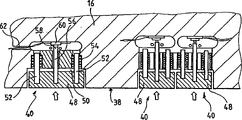
Fig. 2 is the detailed sectional view of expression force transducer structure of the present invention;
Fig. 3 is a curve relation figure of representing stressed/elongation relation;
Fig. 4 is that expression is by the determined pressue-graph of apparatus of the present invention.
Embodiment
In Fig. 1, the overall expression of label 10 extension measurement device of the present invention, this device mainly comprises a framework 12, a deformable structure body 14 is housed, in order to be contained in hosiery goods (not comprising foot) of having worked out on the whole length on it.
In their opposite end 26,28, branch 16,18 is connected in the expansion instrument that is used for that it is separated from each other and does relative gyration with respect to pivot 24, can by the class methods that keep static such as the end 26 that makes bottom branch 16 and the end 28 of top branch 18 is moved realize this each other separately, this is by driver 32, for example but the electric drive of its speed and amplitude program adjusting is finished by its bar portion 30.For example, electric drive can be by a stepper motor, and its rotating speed generally can be regulated in 0 to 500 mm/min (mm/min) scope, and the opening amplitude between 14 liang of arms of deformable structure body 16,18 can be regulated in 0 to 400mm scope.
Move along the guide slit 34 of vertical slideway 36 mobile terminal 28.
The outer table skeleton of bottom branch 16 can be rectilinear, and described branch is provided with a plurality of force transducers 40 that can distribute along branch 16 at Chosen Point.
The outer table skeleton of top branch 18 can be curved, and is corresponding with the overall shape of leg.
For making can both being measured with different types of goods of different size, top branch 18 can be exchanged with other similar branches with different profiles 42, and similar branch can have difformity.In addition, can adjust pivoting point 24, for example raise pivoting point 24 to hold the hosiery size of larger diameter.
By example, can settle 12 sensors 40 along bottom branch 16, make it distribute consistent thus with the measuring point of measuring point b, b1, c, d, e, f and the g standard of known " Huo Hansitan standard " (Hohenstein standard).Be preferably in c, d, e, f and place, g point position and put two sensors, produce 12 sensors altogether of seven measuring points thus.
Consider the factor of goods, only need use the part of sensor, for example the sensor at a b and b1 place is used for measuring socks, sensor at a b, b1 and c place is used for measuring knee length stocking, sensor at a b, b1, c, d, e and f place is used for measuring stockings, and the sensor of being had a few is used for measuring close-fitting panty hose.
Consistent for guaranteeing to measure the hosiery measuring point that is limited with the Huo Hansitan standard, it is very important that hosiery is longitudinally accurately placed on the anchor clamps 14, usually degree of accuracy is between positive and negative 3mm, measurement begins (concluding volume of weft yarn before arriving the heel line) from the heel line, and etching one suitable mark is represented the position of heel line on branch 16 and 18.
A plurality of sensors 40 are determined the acting force of hosiery to surface 38, record parameter and transfer to the microcomputer 46 that is used for handling, storing and show collected data by an interface 44.
Fig. 2 has represented a wherein sensor in detail.
One measures button 48,30mm long (on the left side of Fig. 2) is generally arranged in single-sensor, retransmit at a pair of that (on the right of Fig. 2) has 2*20mm long in the sensor, they are housed inside in the hole 50 of bottom branch 16, and button Face is concordant with the outer surface 38 of described bottom branch.For making minimise friction, button 48 is installed on the guide 52 that links to each other with ball bush 58, so that move perpendicular to the direction of branch's 16 contoured surfaces 38 on its edge.The power that acts on button 48 is sent to and force transducer 60 contacted fingers 58 by bar portion 56.For example model is ELFS60B-25N-/M1.0,5M/MLL, trade mark are the sensor of En Tela (ENTRAN), this sensor is one can measure the adaptability to changes survey sensor of the pressure in 0 to 25 newton (N) scope, and has characteristics such as quite low non-linear, drift, hysteresis.Sensor links to each other with lead 62 (power supply and measurement), and this lead extends to the interface 44 of microcomputer along bottom branch 16.
It is as described below to measure rule.
At first, make each branch 16 and 18 of extension measurement instrument be in the position of minimum spacing, hosiery is placed on the extension measurement instrument with hand, hosiery should be in non-tensioned state, does not promptly have any elastic deformation.As mentioned above, begin the shank of hosiery is placed on the extension measurement instrument from the heel line, the remaining part of hosiery is also launched by nonelastic shifting ground, surpasses the length (surpassing entire length still is that partial-length depends on that product is socks, knee length stocking or a pair of panty hose etc.) of extension measurement instrument thus.Can observe,, become simple and easy and rapid in place on the hosiery anti-theft device because the extension measurement instrument does not have the sufficient shape (unlike other known extension measurement instrument) of square.
Two branches are separated gradually by driver 30,32, all delivered in real time in each CALCULATION OF PARAMETERS machine of record by the signal that sensor 40 is gathered.The software utilization is calculated the displacement of each check point by the amplitude of driver transmission.
Can observe, must be handled by the parameter that each sensor provides in this stage, therefore the power 64 (Fig. 1) that is recorded by sensor is perpendicular to the outline of straight line 38 of bottom branch 16, need converting to force 66, this is the power of hosiery hosiery along weft direction 68 practical functions, and this is the parameter of required acquisition.Here, data are obtained software and need be determined a suitable coefficient of strain for each measurement point (each sensor) with between each step of mobile branch 18 openings.
To a given sensor, when opening, two branches make the directed force F of hosiery extending transversely Δ X have the feature of curve 70 as shown in Figure 3, the family curve (delayed action) when it is different from two branches closure.For assembly is tended towards stability, control this device and carry out continuous circulation, wherein two branches 16,18 remove/closure relative to each other, the final data that is obtained can by for the third time or the 6th circulation provide.In each cycle stage, promptly remove and in closed two stages the measuring point number in each stage generally be 500 points.
Can observe, data are not to obtain simultaneously at each measuring point.The elastic deformation of hosiery only starts from the environment for use that elongation that the extension measurement instrument transmitted accords with hosiery, thus elastic deformation could obtain when only between each measuring point, different spacing being arranged, so with spacing consistent between each measuring point with plane width as zero.
Because hysteresis quality, a simple elongation amount can cause two gangs of different power F1 and F2; Its average magnitude can be used as the amount of recording.
On the basis of the data that collected, software can be assessed out various parameter, for example:
Anchorage force P on each point;
Toughness at each point;
Each point is with respect to the decrement at socks ankle place; And
The difference of successively decreasing between the different measuring points.
Data can be displayed on the display, also can attach other parameters, for example lot number, Test No. and statistics (standard deviation in a collection of) etc.
Stressed/elongated features the curve (Fig. 3) that can observe each measuring point to be perceiving abnormality by vision-based detection, thereby gets rid of suspicious measurement data.
This device also can be shown in the pressure curve of tested hosiery on the screen, and this curve provides hosiery and is distributed in different measuring points position b, the applied pressure P of b1, c... institute value on the length.
Claims (9)
1. a nondestructive deformeter (10) that is used to measure the supporting power that is applied by elasticity hosiery print is characterized in that, comprising:
One anchor clamps (14) are equipped with a print thereon, and described anchor clamps have two elongated branches (16,18);
The expansion instrument (30,32) that described branch is separated from each other with described branch opposite end (26,28) acting in conjunction perpendicular to length direction;
Be used for controlling described expansion instrument and and the removable branch control device that moves it and separate gradually each other with control mode thus; And
Some sensors (40) are along the length distribution of at least one branch and can measure the power that is acted locally on this branch by the print that is positioned at the sensor place, and measured value is expressed with the component perpendicular to the power of described branch profile.
2. install according to claim 1, it is characterized in that, described branch is by being pivotally connected to the far-end of that end that cooperates with described expansion instrument, the separated mobile gyration that becomes around corresponding pivoting point of two branches.
3. install according to claim 1, it is characterized in that, sensor (40) comprises and measures the sensing element that button (48) contacts that described measurement button (48) is concordant with the outer contour of its place branch.
4. device according to claim 1 is characterized in that, described expansion instrument comprises that the rectilinear branches (16) of a belt sensor and a profile are consistent with the leg shape and is suitable for holding the branch of a curve (18) of print.
5. install according to claim 1, it is characterized in that described expansion instrument (30,32) is a tracker action.
6. install according to claim 1, it is characterized in that, described device comprises some facilities in order to determine the transverse extension amount (Δ X) of print in the position of each sensor, and this amount is the function of expansion instrument with the interval of two branches generation.
7. as device as described in the claim 5, it is characterized in that described device comprises that some facilities are used for writing down the many to measured value of each sensor, each comprises power of recording (F) and elongation (Δ X) to measured value.
8. as device as described in claim 6 and 7, it is characterized in that, comprise being used for the device of dynamic deterministic force/elongation characteristic.
9. install according to claim 1, it is characterized in that, comprise the device that is used for determining to put on the anchorage force curve (P) on its whole length (l) by print.
Applications Claiming Priority (2)
| Application Number | Priority Date | Filing Date | Title |
|---|---|---|---|
| FR9910366A FR2797393B1 (en) | 1999-08-10 | 1999-08-10 | DEVICE FOR THE NON-DESTRUCTIVE EXTENSOMETRIC MEASUREMENT OF CONTAINMENT FORCES LIKELY TO BE EXERCISED BY A LOW OR ADHESIVE-TYPE CONTAINMENT |
| FR99/10366 | 1999-08-10 |
Publications (2)
| Publication Number | Publication Date |
|---|---|
| CN1320209A CN1320209A (en) | 2001-10-31 |
| CN1177210C true CN1177210C (en) | 2004-11-24 |
Family
ID=9549051
Family Applications (1)
| Application Number | Title | Priority Date | Filing Date |
|---|---|---|---|
| CNB00801650XA Expired - Fee Related CN1177210C (en) | 1999-08-10 | 2000-08-08 | Device for measuring retention forces exerted by an orthesis such as support stockings or tights |
Country Status (13)
| Country | Link |
|---|---|
| US (1) | US6499356B1 (en) |
| EP (1) | EP1123496B1 (en) |
| JP (1) | JP2003506709A (en) |
| CN (1) | CN1177210C (en) |
| AT (1) | ATE284028T1 (en) |
| AU (1) | AU768855B2 (en) |
| CA (1) | CA2346385C (en) |
| DE (1) | DE60016370T2 (en) |
| ES (1) | ES2233430T3 (en) |
| FR (1) | FR2797393B1 (en) |
| HK (1) | HK1041313B (en) |
| PT (1) | PT1123496E (en) |
| WO (1) | WO2001011337A1 (en) |
Families Citing this family (9)
| Publication number | Priority date | Publication date | Assignee | Title |
|---|---|---|---|---|
| FR2852421B1 (en) | 2003-04-22 | 2005-06-17 | DEVICE FOR AIDING THE SELECTION OF A CONTAINMENT ORTHESIS AND ITS ADAPTATION TO THE MORPHOLOGY OF A MEMBER | |
| EP1703269A1 (en) * | 2005-03-14 | 2006-09-20 | Salzmann AG | Apparatus for testing elastic material for leg garments |
| FR2942130B1 (en) | 2009-02-13 | 2019-09-06 | Laboratoires Innothera | METHOD FOR EVALUATING THE LOWER LIMESTONE OF A TRICOTED ELASTIC VENOUS CONTENT ORTHESIS |
| FR2949319B1 (en) * | 2009-09-01 | 2011-08-26 | Innothera Lab Sa | METHOD OF CHARACTERIZING A TRICOTED ELASTIC VEINOUS CONTENT ORTHESIS. |
| DE102012208639A1 (en) * | 2012-05-23 | 2013-11-28 | Karl Otto Braun Gmbh & Co. Kg | Measuring device for determining the compression pressure of therapeutic compression measures, in particular compression stockings or compression bandages |
| US10307795B2 (en) * | 2016-05-04 | 2019-06-04 | Fabscrap, Inc. | Scalable systems and methods for classifying textile samples |
| CN106018084A (en) * | 2016-05-20 | 2016-10-12 | 山东省纺织科学研究院 | Compression performance tester for compression socks |
| CN109269712A (en) * | 2018-07-25 | 2019-01-25 | 国营芜湖机械厂 | A kind of aircraft engine oil pressure difference ground checkout equipment |
| CN114577603B (en) * | 2022-02-16 | 2024-03-08 | 安徽省嘉佰利针织品有限公司 | Adjustable sock body opening detection equipment |
Family Cites Families (10)
| Publication number | Priority date | Publication date | Assignee | Title |
|---|---|---|---|---|
| US2175661A (en) * | 1938-05-18 | 1939-10-10 | Harry J Gordon | Hose and stocking drier |
| US3503257A (en) * | 1968-05-09 | 1970-03-31 | Pilot Res Corp | Garment testing apparatus |
| US3750291A (en) * | 1971-04-05 | 1973-08-07 | Us Industries Inc | Panty hose measuring means |
| US4137763A (en) * | 1978-06-21 | 1979-02-06 | Rampon Products, Incorporated | Hosiery testing apparatus |
| US4491255A (en) * | 1983-05-20 | 1985-01-01 | Intech Corporation | Collapsible hosiery form |
| GB2168156B (en) * | 1984-12-04 | 1988-08-17 | Nat Res Dev | Measuring apparatus |
| US5776123A (en) * | 1993-07-28 | 1998-07-07 | Kimberly-Clark Worldwide, Inc. | Garment with tactile position indicators |
| US5458265A (en) * | 1993-11-18 | 1995-10-17 | Levi Strauss & Co. | Automated garment finishing system |
| US5497235A (en) * | 1995-01-12 | 1996-03-05 | Monarch Knitting Machinery Corporation | Inspecting and grading apparatus for hosiery and method of inspecting same |
| FR2764796B1 (en) * | 1997-06-23 | 1999-10-15 | Innothera Topic Int | DEVICE FOR ESTABLISHING A SIMULTANEOUS MAP OF PRESSURES LIKELY TO BE APPLIED BY A COMPRESSIVE ORTHESIS ON A PART OF THE BODY, PARTICULARLY ON THE LEG |
-
1999
- 1999-08-10 FR FR9910366A patent/FR2797393B1/en not_active Expired - Fee Related
-
2000
- 2000-08-08 DE DE60016370T patent/DE60016370T2/en not_active Expired - Fee Related
- 2000-08-08 CA CA002346385A patent/CA2346385C/en not_active Expired - Fee Related
- 2000-08-08 AU AU68517/00A patent/AU768855B2/en not_active Ceased
- 2000-08-08 PT PT00956640T patent/PT1123496E/en unknown
- 2000-08-08 EP EP00956640A patent/EP1123496B1/en not_active Expired - Lifetime
- 2000-08-08 ES ES00956640T patent/ES2233430T3/en not_active Expired - Lifetime
- 2000-08-08 WO PCT/FR2000/002274 patent/WO2001011337A1/en active IP Right Grant
- 2000-08-08 US US09/787,441 patent/US6499356B1/en not_active Expired - Fee Related
- 2000-08-08 JP JP2001515944A patent/JP2003506709A/en active Pending
- 2000-08-08 AT AT00956640T patent/ATE284028T1/en not_active IP Right Cessation
- 2000-08-08 CN CNB00801650XA patent/CN1177210C/en not_active Expired - Fee Related
-
2002
- 2002-04-23 HK HK02103036.8A patent/HK1041313B/en not_active IP Right Cessation
Also Published As
| Publication number | Publication date |
|---|---|
| CA2346385C (en) | 2006-10-10 |
| JP2003506709A (en) | 2003-02-18 |
| CN1320209A (en) | 2001-10-31 |
| AU6851700A (en) | 2001-03-05 |
| EP1123496B1 (en) | 2004-12-01 |
| WO2001011337A1 (en) | 2001-02-15 |
| CA2346385A1 (en) | 2001-02-15 |
| ES2233430T3 (en) | 2005-06-16 |
| ATE284028T1 (en) | 2004-12-15 |
| PT1123496E (en) | 2005-04-29 |
| US6499356B1 (en) | 2002-12-31 |
| HK1041313A1 (en) | 2002-07-05 |
| FR2797393B1 (en) | 2001-10-26 |
| HK1041313B (en) | 2005-05-27 |
| EP1123496A1 (en) | 2001-08-16 |
| FR2797393A1 (en) | 2001-02-16 |
| DE60016370D1 (en) | 2005-01-05 |
| AU768855B2 (en) | 2004-01-08 |
| DE60016370T2 (en) | 2005-12-22 |
Similar Documents
| Publication | Publication Date | Title |
|---|---|---|
| CN1177210C (en) | Device for measuring retention forces exerted by an orthesis such as support stockings or tights | |
| Rebman et al. | A tactile sensor with electrooptical transduction | |
| CN2831044Y (en) | Integrated error electronic test board for ceramic tile | |
| US20210404925A1 (en) | Material performance testing including improved load detection | |
| EP1126237A3 (en) | Rotating and pivoting device for the touch probe of a coordinate measuring machine | |
| CN108106931A (en) | A kind of test fixture for ω structure railway elastic bars | |
| US20080229843A1 (en) | Tensile Tester | |
| CN108582154A (en) | A kind of Bearing testing robot arm | |
| Lloyd et al. | An examination of a ‘wide-jaw’test for the determination of fabric Poisson ratios | |
| CN207487640U (en) | A kind of measuring for verticality instrument based on contact digital sensor | |
| CN209802877U (en) | Double-end clamping and three-bending method fiber material bending resistance testing device | |
| CN107621234B (en) | High-precision ultra-micro force measurement part surface shape tracking device | |
| EP1731096A1 (en) | Devices and methods for characterizing medical compression garments | |
| CN220542243U (en) | Weighing apparatus detects clamping device | |
| Salisbury et al. | Image-based non-contact method to measure cross-sectional areas and shapes of tendons and ligaments | |
| CN212275139U (en) | Target-shaped pressure measuring assembly with adjustable angle | |
| CN100420932C (en) | Woolen-sweater-like elastic fabric collarband stretch measuring instrument | |
| RU75050U1 (en) | DEVICE FOR DETERMINING DEFORMATION PROPERTIES OF KNITTED FABRIC | |
| CN218566397U (en) | Warp knitting machine connecting long shaft coaxiality measuring device | |
| CN109580397A (en) | A kind of method and device measuring fatigue crack growth rate | |
| CN220040142U (en) | Fabric linear density testing device | |
| CN205352676U (en) | Control shaft detection equipment | |
| CN218445502U (en) | Rapid untwisting mechanism of twist instrument | |
| CN220690647U (en) | Elasticity testing arrangement is used in clothing processing | |
| TWI344380B (en) |
Legal Events
| Date | Code | Title | Description |
|---|---|---|---|
| C06 | Publication | ||
| PB01 | Publication | ||
| C10 | Entry into substantive examination | ||
| SE01 | Entry into force of request for substantive examination | ||
| C14 | Grant of patent or utility model | ||
| GR01 | Patent grant | ||
| C19 | Lapse of patent right due to non-payment of the annual fee | ||
| CF01 | Termination of patent right due to non-payment of annual fee |