CN1174503C - Manufacturing method of separator for alkaline battery - Google Patents
Manufacturing method of separator for alkaline battery Download PDFInfo
- Publication number
- CN1174503C CN1174503C CNB991069153A CN99106915A CN1174503C CN 1174503 C CN1174503 C CN 1174503C CN B991069153 A CNB991069153 A CN B991069153A CN 99106915 A CN99106915 A CN 99106915A CN 1174503 C CN1174503 C CN 1174503C
- Authority
- CN
- China
- Prior art keywords
- cylinder
- separator
- cylindrical
- base paper
- length
- Prior art date
- Legal status (The legal status is an assumption and is not a legal conclusion. Google has not performed a legal analysis and makes no representation as to the accuracy of the status listed.)
- Expired - Lifetime
Links
Images


Classifications
-
- H—ELECTRICITY
- H01—ELECTRIC ELEMENTS
- H01M—PROCESSES OR MEANS, e.g. BATTERIES, FOR THE DIRECT CONVERSION OF CHEMICAL ENERGY INTO ELECTRICAL ENERGY
- H01M50/00—Constructional details or processes of manufacture of the non-active parts of electrochemical cells other than fuel cells, e.g. hybrid cells
- H01M50/40—Separators; Membranes; Diaphragms; Spacing elements inside cells
- H01M50/463—Separators, membranes or diaphragms characterised by their shape
- H01M50/469—Separators, membranes or diaphragms characterised by their shape tubular or cylindrical
-
- H—ELECTRICITY
- H01—ELECTRIC ELEMENTS
- H01M—PROCESSES OR MEANS, e.g. BATTERIES, FOR THE DIRECT CONVERSION OF CHEMICAL ENERGY INTO ELECTRICAL ENERGY
- H01M50/00—Constructional details or processes of manufacture of the non-active parts of electrochemical cells other than fuel cells, e.g. hybrid cells
- H01M50/40—Separators; Membranes; Diaphragms; Spacing elements inside cells
- H01M50/409—Separators, membranes or diaphragms characterised by the material
- H01M50/411—Organic material
- H01M50/429—Natural polymers
- H01M50/4295—Natural cotton, cellulose or wood
-
- H—ELECTRICITY
- H01—ELECTRIC ELEMENTS
- H01M—PROCESSES OR MEANS, e.g. BATTERIES, FOR THE DIRECT CONVERSION OF CHEMICAL ENERGY INTO ELECTRICAL ENERGY
- H01M50/00—Constructional details or processes of manufacture of the non-active parts of electrochemical cells other than fuel cells, e.g. hybrid cells
- H01M50/40—Separators; Membranes; Diaphragms; Spacing elements inside cells
- H01M50/409—Separators, membranes or diaphragms characterised by the material
- H01M50/44—Fibrous material
-
- Y—GENERAL TAGGING OF NEW TECHNOLOGICAL DEVELOPMENTS; GENERAL TAGGING OF CROSS-SECTIONAL TECHNOLOGIES SPANNING OVER SEVERAL SECTIONS OF THE IPC; TECHNICAL SUBJECTS COVERED BY FORMER USPC CROSS-REFERENCE ART COLLECTIONS [XRACs] AND DIGESTS
- Y02—TECHNOLOGIES OR APPLICATIONS FOR MITIGATION OR ADAPTATION AGAINST CLIMATE CHANGE
- Y02E—REDUCTION OF GREENHOUSE GAS [GHG] EMISSIONS, RELATED TO ENERGY GENERATION, TRANSMISSION OR DISTRIBUTION
- Y02E60/00—Enabling technologies; Technologies with a potential or indirect contribution to GHG emissions mitigation
- Y02E60/10—Energy storage using batteries
-
- Y—GENERAL TAGGING OF NEW TECHNOLOGICAL DEVELOPMENTS; GENERAL TAGGING OF CROSS-SECTIONAL TECHNOLOGIES SPANNING OVER SEVERAL SECTIONS OF THE IPC; TECHNICAL SUBJECTS COVERED BY FORMER USPC CROSS-REFERENCE ART COLLECTIONS [XRACs] AND DIGESTS
- Y10—TECHNICAL SUBJECTS COVERED BY FORMER USPC
- Y10T—TECHNICAL SUBJECTS COVERED BY FORMER US CLASSIFICATION
- Y10T29/00—Metal working
- Y10T29/49—Method of mechanical manufacture
- Y10T29/49002—Electrical device making
- Y10T29/49108—Electric battery cell making
- Y10T29/49114—Electric battery cell making including adhesively bonding
-
- Y—GENERAL TAGGING OF NEW TECHNOLOGICAL DEVELOPMENTS; GENERAL TAGGING OF CROSS-SECTIONAL TECHNOLOGIES SPANNING OVER SEVERAL SECTIONS OF THE IPC; TECHNICAL SUBJECTS COVERED BY FORMER USPC CROSS-REFERENCE ART COLLECTIONS [XRACs] AND DIGESTS
- Y10—TECHNICAL SUBJECTS COVERED BY FORMER USPC
- Y10T—TECHNICAL SUBJECTS COVERED BY FORMER US CLASSIFICATION
- Y10T29/00—Metal working
- Y10T29/49—Method of mechanical manufacture
- Y10T29/49002—Electrical device making
- Y10T29/49108—Electric battery cell making
- Y10T29/49115—Electric battery cell making including coating or impregnating
Landscapes
- Chemical & Material Sciences (AREA)
- Chemical Kinetics & Catalysis (AREA)
- Electrochemistry (AREA)
- General Chemical & Material Sciences (AREA)
- Primary Cells (AREA)
- Cell Separators (AREA)
Abstract
用于碱性电池的一种新型分隔件,可以防止分隔件端部的变形,还可以防止当有外力作用在电池上时在电池内部发生短路。其特征在于分隔件原纸沿纵向的抗拉强度与分隔件原纸沿宽度方向的抗拉强度之间的比值在2/1至1/1的范围内。本发明提供了制造这种分隔件的一种新方法,包括以下步骤:卷绕所说原纸以构成一个圆柱体;在保持所说圆柱体形状的同时实施密封底部成型步骤;热粘合以封闭该端部;将所说圆柱体从所说圆柱体形夹具上卸下。
A new type of separator for alkaline batteries that prevents deformation of the ends of the separator and also prevents short circuits from occurring inside the battery when external force is applied to the battery. It is characterized in that the ratio between the tensile strength of the base paper of the separator along the longitudinal direction and the tensile strength of the base paper of the separator along the width direction is in the range of 2/1 to 1/1. The present invention provides a new method of manufacturing such a separator, comprising the steps of: winding said base paper to form a cylinder; performing a sealing bottom forming step while maintaining the shape of said cylinder; heat bonding to close The end; said cylinder is removed from said cylinder-shaped jig.
Description
技术领域technical field
本发明总的涉及一种碱性电池的分隔件的制造方法。The present invention generally relates to a method of making a separator for an alkaline battery.
背景技术Background technique
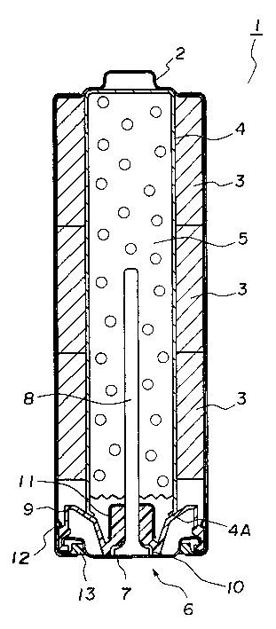
如图1所示,通常所知的碱性电池如LR-6型碱性电池包括底端用作阴极的一个圆柱体形外壳2、一层导电隔膜(未示出)、堆垒在阴极圆柱体形外壳2中的三个圆柱体形阴极混合物3、一个具有底端的圆柱体形分隔件4、浸渍在所述分隔件4和阴极混合物中的一种电解液、和以凝胶形式存在的锌阳极活性物质5。As shown in Fig. 1, generally known alkaline battery such as LR-6 type alkaline battery comprises a
阴极金属外壳2具有一个开口,一个密封件6隐蔽地安装在该开口上。该密封件6包括一个阳极端7、通过点焊和类似方式固定在该阳极端片7的内侧中央区域上的一个集流电极8、利用设置在其间的密封材料固定在集流电极8上的一个垫圈9、和牢固地固定在阴极外壳2的开口上的一个环形密封帽11。当集流电极8插入凝胶状锌阳极活性物质5中时,分隔件4的一端4A被垫圈9向内压迫从而向内弯曲,在分隔件端部4A向内弯曲的同时,阴极外壳2的开口端缝隙被堵严,垫圈9的外圆周部分夹紧在阳极端片7的外圆周部分与阴极外壳2的一个端部之间,从而使得阴极外壳2的开口被密封件6密封住。The
在阴极金属外壳2的外表面上,覆盖有包装标签12,近来这种包装标签已经替代了传统的金属套,以增加电池的内部体积,这种标签被称作“收缩粘性标签”或简称为“标签”,在阳极端片7的外圆周部分与标签12之间设置有一个环形阳极垫圈13。On the outer surface of the
参见图2,分隔件4通过以下步骤制成,转动一卷20分隔件原纸21,沿纵向拉伸卷纸的一端,并根据所制分隔件的长度(高度)将原纸切割成预定长度,然后将预定长度的原纸21借助于一根心轴(未示出)沿图中纵向旋转以形成如图所示的圆柱形结构。然后将圆柱形原纸在其侧部和底部热粘合以形成具有封闭底端的圆柱形结构。因为在从切割步骤进入到将切割的原纸卷绕并粘结以构成圆柱形结构的卷绕步骤时必须将分隔件原纸21转动一个直角以改变其移动方向,所以如上所述的这种制造分隔件的传统方法需要大量的时间和人力来完成分隔件的制造,这种方法的生产率限制为最高每分钟100件。Referring to Fig. 2,
所以,如果需要每分钟生产大约600个分隔件4,就需要如图3所示,将一卷20分隔件原纸21沿纵向旋转,沿纵向(水平方向)拉伸原纸,然后按照预定长度切割,并利用一个心轴沿所述纵向转动卷绕成圆柱形,然后在其侧部和下端部热粘合圆柱形原纸,从而形成具有封闭底端的圆柱形结构的一个圆柱形分隔件。这种方法在从切割步骤进入卷绕步骤时不需要改变原纸21的移动方向,因此能够提高生产率。Therefore, if it is necessary to produce about 600
但是,按照图3所示的生产方法,将原纸21沿水平方向旋转并沿纵向拉伸以进行切割,然后沿水平方向转动,使分隔件4的轴向与原纸21卷20的宽度方向重合,所以,当分隔件4的端部4A(图1所示)被密封件6的垫圈9沿径向向内推压时,这种圆柱形分隔件4很可能发生变形。如果产生这种变形,当碱性电池1受到震动或振动时,凝胶状锌阳极活性物质5就会从分隔件4与垫圈9之间的缝隙进入阴极活性物质3中,结果造成短路。However, according to the production method shown in FIG. 3 , the
下面将参照图4A、4B、4C和4D更加具体地介绍如图3所示和参照图3所述的分隔件制造方法的一个实例。在图4A中,将卷状20的原纸21切割成预定长度,并将切割成的原纸21卷绕形成一个圆柱体22,然后利用一个适合的馈送设备(未示出)将其送入底部成形步骤,将圆柱体的一端热粘合以形成封闭的底端。One example of the separator manufacturing method shown in and described with reference to FIG. 3 will be described in more detail below with reference to FIGS. 4A , 4B, 4C, and 4D. In Fig. 4A, the
为了使封闭底端具有可靠的密封效果,在热粘合之前先使圆柱体的端部弯曲。也就是说,如图4B所示,将一根轴25插入圆柱体22中,用一个刀片状模具24向下按压圆柱体22的上端部以形成如图4C所示的凹陷,然后如图4D所示用一个热卷曲模具29按压圆柱体22的凹陷上端部,从而如图4E所示形成一个半球形顶端22a。由此制成传统的分隔件4。In order to obtain a reliable sealing effect at the closed bottom end, the ends of the cylinder are bent before thermal bonding. That is, as shown in FIG. 4B, a
然而,在这种传统的分隔件制造方法中存在一些不便利和困难之处。However, there are some inconveniences and difficulties in this conventional manufacturing method of the separator.
第一,必须利用馈送设备将圆柱体22传送到预定位置,所以,在传送过程中由于施加在圆柱体22上的某些机械原因和/或震动的影响圆柱体22的开口端部有可能意外地变形或塌陷,导致生产率的严重下降。First, the
第二、当在圆柱体22的上部形成一个凹陷22b时,在很大程度上与圆柱体22的物理性质,如硬度有关,在有些情况下难以形成所需的凹陷,所以密封底端22b的密封(阻塞)特性不理想或者不令人满意。如果通过调节刀片状模具24作用在圆柱体22顶部的时间和压力强制形成凹陷22b,有时会造成圆柱体22的损坏和降低生产率。因此,必须认真明确地选择制作分隔件的原纸材料,而这种选择是很麻烦的,需要付出更多的时间和劳动。Second, when a
发明内容Contents of the invention
本发明的一个目的是提供制造用于蓄电池或电池如碱性电池的分隔件的新方法,这种方法能够确保分隔件底部的密封特性和分隔件的高生产率。An object of the present invention is to provide a new method of manufacturing separators for accumulators or batteries such as alkaline batteries, which ensures the sealing properties of the bottom of the separators and high productivity of the separators.
为此,本发明提供一种用于制造碱性电池的分隔件的方法,该方法包括以下步骤:To this end, the present invention provides a method for manufacturing a separator for alkaline batteries, the method comprising the steps of:
(1)卷绕一个用于分隔件的原纸以形成一个圆柱体,(1) winding a base paper for a separator to form a cylinder,
(2)利用一个圆柱体形夹具保持所述圆柱体的形状并对该圆柱体的一端进行热处理以便封闭该端,由此形成一个封闭端,其中该圆柱体形夹具具有一个夹持孔,该夹持孔的直径等于或大于该圆柱体的外径并且该夹持孔的长度大于该圆柱体的长度的一半,当通过该热处理封闭所述圆柱体的所述端部时,一个棒状模具被压到所述圆柱体的所述端部上以使所述的圆柱体端部的一侧部凹陷,从而使所述侧部弯折成直角地形成一个折叠部分,接着,一个热卷曲模具被压在所述的圆柱体端部上,(2) Hold the shape of the cylinder with a cylindrical jig having a clamping hole and heat-treat one end of the cylinder so as to close the end, thereby forming a closed end. The diameter of the hole is equal to or greater than the outer diameter of the cylinder and the length of the holding hole is greater than half the length of the cylinder, and when the end of the cylinder is closed by the heat treatment, a rod-shaped mold is pressed to on the end of the cylinder so that one side of the end of the cylinder is recessed so that the side is bent at right angles to form a folded portion, and then a heat crimping die is pressed on On the end of the cylinder,
(3)使所述圆柱体从所述圆柱体形夹具上卸下来。(3) The cylinder is detached from the cylinder-shaped jig.
这里所称的分隔件意指各种分隔件,其中包括上述的具有一个一体的密封底端的圆柱形分隔件,和其它类型的分隔件如不具有一体的密封底端的圆柱形分隔件。在后一种情况下,可以在所述开口底端使用一个杯形片或其它分隔部件封闭所述底端。The spacer referred to herein means various spacers, including the above-mentioned cylindrical spacer having an integral sealed bottom end, and other types of spacers such as cylindrical spacers not having an integral sealed bottom end. In the latter case, a cup or other dividing member may be used at the open bottom end to close the bottom end.
根据本发明的分隔件,分隔件原纸的纤维取向是松驰或松散的,从而使得所述分隔件原纸沿纵向的抗拉强度与分隔件原纸沿宽度方向的抗拉强度的比值在2/1至1/1的范围内。采用这种结构,即使在分隔件用于其中分隔件开口端部在密封件垫圈作用下径向向内弯曲的类型的电池时,分隔件的上端部也不会变形或损坏。因此,即使当电池受到诸如震动或振动等外力作用时,也不用担心或不存在在电池中发生短路的危险。所以,能够提高分隔件以及电池的生产率。According to the separator of the present invention, the fiber orientation of the base paper for the separator is loose or loose, so that the ratio of the tensile strength of the base paper for the separator in the longitudinal direction to the tensile strength of the base paper for the separator in the width direction is 2/1 to within the range of 1/1. With this structure, even when the separator is used for a battery of the type in which the open end of the separator is bent radially inward by the seal gasket, the upper end of the separator is not deformed or damaged. Therefore, even when the battery is subjected to an external force such as shock or vibration, there is no concern or danger of a short circuit occurring in the battery. Therefore, the productivity of separators and batteries can be improved.
在一个优选实施例中,在原纸的含有水溶性粘胶的预定部分上喷洒水,然后将所述原纸卷绕成圆柱形状从而形成所述圆柱体。在圆柱形原纸的预定喷水部分上施用一个加热片以蒸发水分,同时将原纸热压粘合。所述的水溶性粘胶可以选自聚乙烯醇(PVA)、聚丙烯酸钠(NaPA)等材料。In a preferred embodiment, water is sprayed on a predetermined portion of the base paper containing the water-soluble glue, and then the base paper is wound into a cylindrical shape to form the cylinder. A heating sheet is applied on the predetermined water-spraying part of the cylindrical base paper to evaporate water, and the base paper is thermally pressed and bonded at the same time. The water-soluble adhesive can be selected from polyvinyl alcohol (PVA), sodium polyacrylate (NaPA) and other materials.
在一个优选实施例中,如此给所述圆柱体卷绕端的上部和下部喷洒水,即喷洒部分的长度大于圆柱体的实际圆周长度。In a preferred embodiment, the upper and lower portions of the coiled end of the cylinder are sprayed with water such that the length of the sprayed portion is greater than the actual circumference of the cylinder.
在本发明中,当施用热粘合方法封闭所述圆柱体的一端时,可以使用一个棒状夹具倾斜地压抵所述圆柱体的所述端部以压下所述圆柱体部的一侧并由此使所述侧部以直角弯曲折叠,接着,用一个热卷曲模具压抵所述圆柱体的端部以实施热粘合。In the present invention, when applying thermal bonding to close one end of the cylinder, a rod-shaped jig may be used to obliquely press against the end of the cylinder to depress one side of the cylinder portion and The sides are thus bent and folded at right angles, and a thermal crimp die is pressed against the end of the cylinder to perform thermal bonding.
此外,按照本发明,可取的是,圆柱体的折叠部分的长度大于圆柱体的内径。Furthermore, according to the present invention, it is preferable that the length of the folded portion of the cylinder is greater than the inner diameter of the cylinder.
附图说明Description of drawings
图1为安装有本发明的一个分隔件的一个碱性电池的剖面正视图。BRIEF DESCRIPTION OF THE DRAWINGS Figure 1 is a sectional front view of an alkaline battery fitted with a separator of the present invention.
图2为表示现有技术中制成一个电池分隔件的一种方法示例的示意图。Fig. 2 is a schematic view showing an example of a method of forming a battery separator in the prior art.
图3为表示现有技术中制成一个电池分隔件的另一种方法示例的示意图。Fig. 3 is a schematic view showing an example of another method of forming a battery separator in the prior art.
图4A、4B、4C、4D和4E为表示现有技术中构成一个分隔件的各个步骤的示意图。4A, 4B, 4C, 4D and 4E are diagrams showing various steps of forming a separator in the prior art.
图5A、5B、5C和5D为表示本发明构成一个分隔件的各个步骤的示意图。5A, 5B, 5C and 5D are schematic diagrams showing steps of the present invention to construct a separator.
图6A、6B和6C为表示构成圆柱形分隔件的密封端部的步骤的示意图。6A, 6B and 6C are schematic diagrams showing steps of forming a sealed end portion of a cylindrical partition.
图7为沿图6B中剖线A-A所作的分隔件的放大剖面视图。Fig. 7 is an enlarged sectional view of the separator taken along line A-A in Fig. 6B.
具体实施方式Detailed ways
1.分隔件结构1. Partition structure
例1example 1
首先介绍LR-6型碱性干电池,这种干电池是按照下述方式制成的。First, the LR-6 type alkaline dry battery is introduced, which is manufactured in the following manner.
参见图1,制备阴极活性物质粉末以制成环状阴极活性体3,所述活性物质粉末由92%重量的二氧化锰MnO2、5%重量的石墨、2.5%重量的40%浓度的氢氧化钾水溶液和0.5%重量的粘合剂混合构成,将三个如此制成的环状阴极活性体3设置在一个阴极金属外壳2中。Referring to Fig. 1, the cathode active material powder is prepared to make the annular cathode
然后将本发明的一个分隔件4插在由三个阴极活性体3构成的阴极混合物之中。A
所述分隔件4是通过转动一卷分隔件原纸21,并沿水平方向拉出原纸,切割成长度为81毫米、宽度为56毫米的长方形而制成的。这种原纸21是由维尼纶纤维/人造丝纤维/维尼纶粘合剂制成的,厚度为120微米,宽度为56毫米,并卷绕成一卷。然后利用一根心轴(未示出)沿水平方向转动所述分隔件原纸21以形成卷绕三(3)圈的圆柱形结构,接着在圆筒部分或侧部和底部实施热粘合以形成具有一个密封底端的圆柱形结构,其外径为8.8毫米,高度为48毫米。The
在对大小为200毫米(长度)×15毫米(宽度)的长方形分隔件原纸进行抗拉强度测试之后,选择所需的原纸,其沿纵向的抗拉强度为4.5千克力(45N/15mm),沿宽度方向的抗拉强度为3.0千克力(30N/15mm),抗拉强度比值为1.5/1。After carrying out the tensile strength test on the base paper of the rectangular separator with the size of 200 mm (length) × 15 mm (width), select the required base paper, which has a tensile strength of 4.5 kgf (45N/15mm) in the longitudinal direction, The tensile strength along the width direction is 3.0 kgf (30N/15mm), and the tensile strength ratio is 1.5/1.
然后,将1.1毫升40%的氢氧化钾水溶液施加在所述分隔件4上,并进行老化处理以使分隔件仍然保持原状,从而可以用氢氧化钾将分隔件4和阴极混合物3润湿。Then, 1.1 ml of a 40% potassium hydroxide aqueous solution was applied on the
然后将一种凝胶状阳极活性物质5填充到分隔件4所限定的空间中。这种凝胶状阳极活性物质5是利用69%重量的锌粉、0.4%重量的聚丙烯酸、1.1%重量的氧化锌、和30.5%重量的40%的氢氧化钾水溶液的混合物制备的。A gel-like anode
接着,将一个集流电极8插入凝胶状锌阳极活性物质5中,将一个密封垫9压抵在所述分隔件4的延伸端4A以使延伸端4A向内弯曲,同时,将阴极金属外壳2的开口端向内堵严,使得密封垫9的外侧被夹紧在阳极端片7的外圆周部分和阴极金属外壳2的端部之间,并利用一个密封件6封闭阴极金属外壳2的开口部分。Next, a
然后,在阴极金属外壳2的外表面上粘贴一层包装标签12,近来已经用包装标签取代了传统的金属外套以增加电池的内部体积,这种标签被称为“收缩粘性标签”或简称为“标签”,在所述阳极端7的外圆周部分与阴极金属外壳2的标签12之间设置一个阳极侧绝缘垫圈13。Then, paste a layer of
之后,使如此制造的50个碱性电池1在500G(4900m/s2)重力作用下以阳极端片7朝下的方式下落,检查其内部短路情况,结果没有发现任何一个电池发生内部短路。After that, 50 alkaline batteries 1 produced in this way were dropped under the action of gravity of 500G (4900m/s 2 ) with the
例2Example 2
使用除下列参数以外与前面例1基本相同的分隔件原纸21,并制造50个干电池。就是说,对尺寸为200毫米(长度)×15毫米(宽度)的长方形的分隔件原纸21进行抗拉强度测试,使用纵向抗拉强度为4.5千克力(45N/15mm)、宽度方向抗拉强度为2.2千克力(22N/15mm)、两者比值为2.0/1的原纸,并进行下落测试,结果发现50个电池都没有发生短路。The
例3Example 3
使用除下列参数以外与前面例1基本相同的分隔件原纸21,并制造50个干电池。就是说,对尺寸为200毫米(长度)×15毫米(宽度)的长方形的分隔件原纸21进行抗拉强度测试,使用纵向抗拉强度为4.5千克力(45N/15mm)、宽度方向抗拉强度为3.6千克力(36N/15mm)、两者比值为1.1/1的原纸,并进行下落测试,结果发现50个电池都没有发生短路。The
比较例1Comparative example 1
以按照如图2所示方式制造的传统分隔件作为比较例。沿垂直方向转动如图2所示卷曲的分隔件原纸21,并沿纵向拉出原纸21的一端,然后切割成预定长度。接着,利用一根心轴使原纸21沿水平方向转动以形成圆柱体形状,再对其端部和底部进行热处理以使之相互粘结在一起,构成具有一个封闭底端的圆柱形分隔件4。A conventional separator manufactured as shown in FIG. 2 was taken as a comparative example. The
使用除下列参数以外与前面例1基本相同的分隔件原纸21,并制造50个干电池。就是说,对尺寸为200毫米(长度)×15毫米(宽度)的长方形的分隔件原纸21进行抗拉强度测试,使用纵向抗拉强度为4.5千克力(45N/15mm)、宽度方向抗拉强度为1.7千克力(17N/15mm)、两者比值为2.7/1的原纸,并进行下落测试,结果发现50个电池都没有发生短路。The
比较例2Comparative example 2
使用除下列参数以外与前面例1基本相同的分隔件原纸21,并制造50个干电池。在这个比较例2中,对尺寸为200毫米(长度)×15毫米(宽度)的长方形的分隔件原纸21进行抗拉强度测试,使用纵向抗拉强度为4.5千克力(45N/15mm)、宽度方向抗拉强度为1.7千克力(17N/15mm)、两者比值为2.7/1的原纸,并进行下落测试。在这个比较例(比较例2)中,分隔件是按照图3所示方式制造的。结果在50个电池中发现有7个电池发生了内部短路。The
从上述的测试结果,发现利用如图2所示传统方法制造的分隔件即使在分隔件原纸21的纵向抗拉强度与宽度方向抗拉强度之间的比值大于2的情况下也不会发生内部短路。但是,另一方面,如果纵向抗拉强度与宽度方向抗拉强度之间的比值大于2,则按照如图3所示方法制造的分隔件4会发生内部短路,而如果这个比值小于2(包括2在内),则没有发现发生短路。From the above-mentioned test results, it was found that the separator manufactured by the conventional method as shown in FIG. short circuit. But, on the other hand, if the ratio between the longitudinal tensile strength and the width direction tensile strength is greater than 2, the
根据本发明,将纵向抗拉强度与宽度方向抗拉强度之间的比值确定为在2/1至1/1的范围。所以,通过沿水平方向转动成卷的分隔件原纸以拉出原纸并切割成预定长度,然后沿水平方向转动拉出的分隔件原纸以形成圆柱体分隔件结构,并使所述圆柱体分隔件结构的端部径向向内弯曲,即在按照图3所示方法制造分隔件的情况下,也能够防止分隔件端部的变形。因此,即使在有外力例如振动或震动施加到电池上时,也能够防止产生内部短路。所以,在不出现分隔件废品的前提下可以提高分隔件以及电池本身的生产率。According to the present invention, the ratio between the tensile strength in the longitudinal direction and the tensile strength in the width direction is determined to be in the range of 2/1 to 1/1. Therefore, by turning the roll of separator base paper in the horizontal direction to pull out the base paper and cut it into a predetermined length, then turning the drawn separator base paper in the horizontal direction to form a cylindrical separator structure, and making the cylindrical separator The ends of the structure are bent radially inwards, ie in the case of manufacturing the separator according to the method shown in FIG. 3 , it is also possible to prevent deformation of the ends of the separator. Therefore, even when an external force such as vibration or shock is applied to the battery, it is possible to prevent an internal short circuit from being generated. Therefore, the productivity of the separator as well as the battery itself can be increased without occurrence of separator waste.
2、分隔件的生产方法2. The production method of the separator
下面,介绍本发明的分隔件制造方法。Next, the manufacturing method of the separator of the present invention will be described.
参照图5A,制备包含水溶性粘合剂的箍状原纸21,并利用一个喷嘴30在对应于卷绕的管状分隔件结构的卷绕端的上部、卷绕端的中部和卷绕端的下部的三个预定部分上喷水,下面将对所述分隔件结构进行介绍。在这种情况下,选择喷水区域的长度大于圆柱体22的整个周边长度。如果需要的话,可以在水中添加少量的水溶性粘合剂。Referring to FIG. 5A , a hoop-shaped
在这之后,将原纸21切割成预定长度,并缠绕在一根心轴32上以构成如图5B所示的圆柱体22。这时,通过将一个加热片(未示出)压在上述含水部分,使包含在所述管形分隔件结构的喷水部分中的水分蒸发。然后,通过使包含在原纸21中的水分蒸发而使水溶性粘合剂固化,从而圆柱体22固化并保持其圆柱形状。固化部分(即喷水部分)为三个点,即分别是圆柱体22卷绕端的上部、中部和下部,除了上述之外,每个喷水区域的长度基本等于或大于管状体22的圆周长度。因此,能够按照要求使圆柱体22保持预定的圆柱体形状。After that, the
在图5C中,将如此形成的圆柱体22从心轴32上卸下,并插入圆柱形加夹具33的夹持孔33a中。夹持孔33a的直径基本等于或略大于圆柱体22的外径D1,其长度大于圆柱体22长度L1的一半,所以圆柱形夹具33能够可靠地固定住所述圆柱体22。然后使由圆柱形夹具33固定的圆柱体22转移到底部成型步骤,由于在所述转移过程中圆柱体22始终由圆柱形夹具33夹持着,所以不用担心或者不存在由于机械原因(例如震动和振动)和/或其自身重量造成圆柱体22开口端部的变形和/或损坏的危险。In FIG. 5C , the
然后,制造工序进入底部成型步骤,同时仍然由圆柱形夹具33夹持着圆柱体22,使用一根轴沿高度方向和径向方向保持住圆柱体22,并使圆柱体22的一端热粘合以封闭其底端,如图6A至6C所示。具体地说,参见图6A,用一个棒状模具27偏斜地按压圆柱体22的上端,使得该圆柱体22的环形上端的半个部分22c如图6B所示方式凹陷,从而该凹陷部分22c相对于圆柱体的长度方向弯曲和折叠成直角。这时,如图7所示,需要留心使凹陷部分22c的折叠长度L2大于圆柱体22的内径D2。在这种状态下,用一个热卷曲模具29压抵在圆柱体22的顶部以如图6C所示进行热粘合,从而在圆柱体22的上端形成一个半球形底部22a。由于如上所述凹陷部分22c折叠成直角,所以可以限制凹陷部分22c的反作用,因而,无论圆柱体22的硬度或其它物理特性如何,都能够改善底部22a的密封或封闭效果。此外,如以上参照图7所述,由于将凹陷部分22c的折叠长度L2设定为大于圆柱体22的内径D2,所以,凹陷部分22c的折叠部分延伸到与圆柱体22的相反侧内壁完全接触和啮合的程度。从而,大大减小了圆柱体22的折叠上端部的反作用力,可以确保底部22a的密封或封闭特性。此外,在底部成型步骤中,圆柱体22仍然插入在圆柱体形夹具33之中,所以在底部成型步骤中能够保持住所述圆柱体,而不会发生任何移动或滑动。Then, the manufacturing process enters the bottom forming step, while still holding the
于是,完成了本发明的分隔件。在本发明中,从形成圆柱体22的起始步骤到底部成型步骤,所述圆柱体22是一直插入所述圆柱体夹具33之中的,所以,能够使圆柱体保持所需的初始形状,进而能够提高分隔件4的生产率。Thus, the separator of the present invention was completed. In the present invention, from the initial step of forming the
下面介绍制造分隔件的示例。An example of manufacturing a divider is described below.
示例AExample A
将20%重量的维尼纶纤维和65-75%的纸浆纤维混合在一起,在该混合物中加入15-5.0%重量的聚乙烯醇系列水溶性粘合剂,制备出厚度为120微米的原纸。20% by weight of vinylon fibers and 65-75% of pulp fibers are mixed together, and 15-5.0% by weight of polyvinyl alcohol series water-soluble binders are added to the mixture to prepare base paper with a thickness of 120 microns.
采用本发明的上述方法,使用这种原纸,制造用于UM-3型碱性干电池的分隔件。分隔件的生产速度为每分钟600个分隔件。Using this base paper, a separator for a UM-3 type alkaline dry battery was produced by the above-mentioned method of the present invention. The separators were produced at a rate of 600 separators per minute.
比较例comparative example
使用在上述示例A中生产的原纸,并采用传统的已知方法生产用于UM-3型碱性干电池的分隔件。以每分钟300个分隔件的生产速度,即示例A的生产率的一半,进行生产。Using the base paper produced in Example A above, a separator for a UM-3 type alkaline dry battery was produced by a conventionally known method. Production was performed at a production rate of 300 separators per minute, half the production rate of Example A.
外观检测external assessment
对根据本发明制成的分隔件和按照现有技术制成的分隔件进行外观检测。其结果是,每分钟发现大约5个分隔件(即大约1.7%)不合格,相反,对于本发明的分隔件没有发现不合格产品。这个测试结果表明,尽管本发明已经将生产速度提高到传统方法的两倍,但是本发明能够以较低的不合格品率保证较高的生产速率(生产率)。Appearance inspection was carried out on the separators made according to the present invention and the separators made according to the prior art. As a result, about 5 separators per minute (ie, about 1.7%) were found to be defective, whereas no defective products were found for the separator of the present invention. This test result shows that although the present invention has increased the production speed to twice that of the conventional method, the present invention can ensure a higher production rate (productivity) with a lower defective rate.
底端的密封测试Bottom seal test
为了比较分隔件底部的密封(封闭)特性,准备了10000个应用根据本发明制成的分隔件的UM-3型碱性电池和10000个应用根据传统方法制成的分隔件的同样类型的碱性电池,在60℃下放置20天,并相对于开路电压进行降压测试。结果发现,对于应用传统分隔件的电池每10000个电池中有3个电池(即0.03%)产生电压下降,但是,另一方面,在应用本发明分隔件的电池中没有发现出现电压下降的情况。所以,可以得出结论,本发明的分隔件相对于传统的分隔件具有更加可靠的密封特性。In order to compare the sealing (sealing) properties of the bottom of the separator, 10000 alkaline cells of UM-3 type to which the separator made according to the present invention was applied and 10000 alkaline cells of the same type to which the separator made according to the conventional method were applied were prepared For permanent batteries, place them at 60°C for 20 days, and conduct a voltage drop test relative to the open circuit voltage. As a result, it was found that 3 batteries per 10,000 batteries (i.e. 0.03%) had a voltage drop for the batteries using the conventional separator, but, on the other hand, no voltage drop was found in the batteries using the separator of the present invention. . Therefore, it can be concluded that the separator of the present invention has more reliable sealing properties than the conventional separator.
根据本发明,所述制造方法包括以下步骤:卷绕分隔件原纸21以形成一个圆柱体22;在利用一个圆柱体夹具33将所形成的圆柱体22保持为圆柱体形状的同时,对圆柱体22实施封闭底部成型步骤,对所述圆柱体的一端进行热处理以封闭该端部从而形成一个封闭端,然后将圆柱体22从圆柱体夹具33上卸下。According to the present invention, the manufacturing method includes the steps of: winding the
根据本发明的制造方法,能够从形成所述圆柱体22的起始步骤开始直到形成封闭底端的最后步骤始终利用圆柱体夹具33夹持住所述圆柱体,所以能够保持所述圆柱体的预定形状。因此,本发明的制造方法能够提高分隔件和电池的生产率。According to the manufacturing method of the present invention, the cylinder can be clamped by the
按照上述方法,可取的是所述圆柱体夹具33具有一个夹持孔23a,该夹持孔的直径基本等于或略大于所述圆柱体22的外径D1,其长度大于所述圆柱体22的长度L1的一半。这个实施例仍然能够确保维持圆柱体22的形状,所以能够进一步提高分隔件的生产率。According to the method described above, it is desirable that the
在另一个实施例中,这样形成所述圆柱体22,使得在包含水溶性粘合剂的原纸的预定部分上喷水,然后将原纸卷成圆柱形。在所述圆柱形的原纸的预定喷水部分使用加热片将水分蒸发,同时,对原纸21进行热粘合。水溶性粘合剂可以选自聚乙烯醇(PVA)、聚丙烯酸钠(NaPA)等。在这个实施例中,水溶性粘合剂成分由于原纸1中水分的蒸发而固化,并且圆柱体22保持了其圆柱形状,所以,可以减少分隔件外观变形现象的发生。因而,提高了分隔件的生产率。In another embodiment, the
在优选实施例中,在所述圆柱体22卷绕端的上下两个部分喷水,喷水部分的长度大于所述圆柱体实际的圆周长度。这将确保维持所述圆柱体22的形状,并且可以使外观变形的发生达到最少。In a preferred embodiment, water is sprayed on the upper and lower parts of the coiled end of the
在本发明的另一个优选实施例中,当通过热处理封闭所述圆柱体22时,可以用一个棒状模具27偏斜地按压圆柱体22的端部以使圆柱体22该端部的一个侧部22c凹陷,并且使所述侧部22c弯曲和折叠成直角,这时,将一个热卷曲模具29按压所述圆柱体22的一端以进行热粘合。在这个实施例中,由于限制了所述圆柱体22的端部22c的反作用,从而改善了通过热粘合获得的底端部22a的密封特性,并且能够提高分隔件和电池的生产率。In another preferred embodiment of the present invention, when sealing the
此外,在本发明的优选实施例中,使所述22圆柱体的折叠部分的长度L2大于所述圆柱体22的内径。这将使端部22c与另一侧端部接触,从而可以进一步改善通过热粘合获得的底部22a的密封效果。Furthermore, in a preferred embodiment of the present invention, the length L2 of the folded portion of the
尽管已经参照一些优选实施例描述了本发明,但是在权利要求书所限定的范围内还可以作出许多改进和变换。Although the invention has been described with reference to some preferred embodiments, many modifications and variations are possible within the scope defined by the claims.
Claims (4)
Applications Claiming Priority (6)
| Application Number | Priority Date | Filing Date | Title |
|---|---|---|---|
| JP147418/1998 | 1998-05-28 | ||
| JP14741898A JP3240995B2 (en) | 1998-05-28 | 1998-05-28 | Manufacturing method of battery separator |
| JP147418/98 | 1998-05-28 | ||
| JP254814/98 | 1998-09-09 | ||
| JP254814/1998 | 1998-09-09 | ||
| JP25481498A JP3475803B2 (en) | 1998-09-09 | 1998-09-09 | Alkaline batteries |
Publications (2)
| Publication Number | Publication Date |
|---|---|
| CN1237803A CN1237803A (en) | 1999-12-08 |
| CN1174503C true CN1174503C (en) | 2004-11-03 |
Family
ID=26477968
Family Applications (1)
| Application Number | Title | Priority Date | Filing Date |
|---|---|---|---|
| CNB991069153A Expired - Lifetime CN1174503C (en) | 1998-05-28 | 1999-05-27 | Manufacturing method of separator for alkaline battery |
Country Status (2)
| Country | Link |
|---|---|
| US (1) | US6270833B1 (en) |
| CN (1) | CN1174503C (en) |
Cited By (1)
| Publication number | Priority date | Publication date | Assignee | Title |
|---|---|---|---|---|
| CN101286553B (en) * | 2008-05-27 | 2010-06-02 | 佛山塑料集团股份有限公司 | A method for improving arch amount of lithium ion cell |
Families Citing this family (13)
| Publication number | Priority date | Publication date | Assignee | Title |
|---|---|---|---|---|
| DE10154896C2 (en) * | 2001-11-12 | 2003-10-16 | Freudenberg Carl Kg | Alkaline cell or battery |
| EP1680824B1 (en) * | 2003-11-05 | 2007-12-19 | Hibar Systems Limited | Separator for cylindrical cells |
| US7659330B2 (en) * | 2005-09-16 | 2010-02-09 | University Of Maine System Board Of Trustees | Thermoplastic composites containing lignocellulosic materials and methods of making same |
| US20070066722A1 (en) * | 2005-09-16 | 2007-03-22 | University Of Maine System Board Of Trustees | Thermoplastic composites containing lignocellulosic materials and methods of making the same |
| US7799455B2 (en) * | 2006-11-29 | 2010-09-21 | The Gillette Company | Battery separator and method of making same |
| JP4199811B2 (en) * | 2007-01-15 | 2008-12-24 | パナソニック株式会社 | Alkaline battery |
| US20080206632A1 (en) * | 2007-02-23 | 2008-08-28 | Wang Ruike R | Battery separator |
| GB201009519D0 (en) * | 2010-06-07 | 2010-07-21 | Nexeon Ltd | An additive for lithium ion rechargeable battery cells |
| US20160141577A1 (en) * | 2014-11-19 | 2016-05-19 | Schlumberger Technology Corporation | Energy Storage Device with An Encapsulated Electrode |
| US11264607B2 (en) | 2016-06-20 | 2022-03-01 | Energizer Brands, Llc | Alkaline electrochemical cell with improved anode and separator components |
| US10581052B2 (en) | 2017-11-07 | 2020-03-03 | Energizer Brands, Llc | Heat applied electrochemical cell separator |
| EP3811429A1 (en) | 2018-06-20 | 2021-04-28 | Energizer Brands, LLC | Electrochemical cell separator |
| CN110667188B (en) * | 2019-09-26 | 2024-12-24 | 宁波倍特瑞能源科技有限公司 | A plug board assembly and diaphragm paper forming equipment |
Family Cites Families (4)
| Publication number | Priority date | Publication date | Assignee | Title |
|---|---|---|---|---|
| JPS5240011B2 (en) * | 1973-03-07 | 1977-10-08 | ||
| JPS57124850A (en) * | 1981-01-27 | 1982-08-03 | Supairaru Shigyo Kk | Cylindrical separator for dry cell and its manufacture |
| JPS5882465A (en) * | 1981-11-10 | 1983-05-18 | Matsushita Electric Ind Co Ltd | Alkaline battery manufacturing method |
| US4620665A (en) * | 1983-08-18 | 1986-11-04 | Nathaniel H. Garfield | Container with integral toggle closure |
-
1999
- 1999-03-17 US US09/270,769 patent/US6270833B1/en not_active Expired - Lifetime
- 1999-05-27 CN CNB991069153A patent/CN1174503C/en not_active Expired - Lifetime
Cited By (1)
| Publication number | Priority date | Publication date | Assignee | Title |
|---|---|---|---|---|
| CN101286553B (en) * | 2008-05-27 | 2010-06-02 | 佛山塑料集团股份有限公司 | A method for improving arch amount of lithium ion cell |
Also Published As
| Publication number | Publication date |
|---|---|
| CN1237803A (en) | 1999-12-08 |
| US6270833B1 (en) | 2001-08-07 |
Similar Documents
| Publication | Publication Date | Title |
|---|---|---|
| CN1174503C (en) | Manufacturing method of separator for alkaline battery | |
| JP2023087895A (en) | CYLINDRICAL BATTERY AND METHOD OF MANUFACTURING CYLINDRICAL BATTERY | |
| WO2003061038B1 (en) | Electric storage battery construction and method of manufacture | |
| CN102024978A (en) | Secondary battery and method of manufacturing the secondary battery | |
| CN102163699B (en) | Alkaline battery | |
| CN1147013C (en) | Solid electrolytic battery | |
| JPH10302827A (en) | Manufacture of electrode group of angular battery | |
| CN1151567C (en) | Cylindrical battery and its manufacturing method and equipment | |
| CN1308778A (en) | Electrochemical cell formed with big mouth open end can | |
| CN1182616C (en) | Manufacturing method of sealed cylindrical nickel metal hydride storage battery | |
| CN1212686C (en) | Closed battery | |
| CN101478048A (en) | Alkaline dry battery and manufacturing method thereof | |
| JP2001043889A (en) | Method of forming flat-shaped wound electrode body and flat-shaped wound electrode body | |
| CN1577939A (en) | Prismatic battery and method for manufacturing the same | |
| JP2006278267A (en) | Non-aqueous electrolyte battery | |
| JP2000294233A (en) | Method for producing positive electrode mixture for alkaline dry battery | |
| JP3475803B2 (en) | Alkaline batteries | |
| JP2009289968A (en) | Coin type cell | |
| JP2725523B2 (en) | Method of manufacturing battery with spiral electrode | |
| CN1204645C (en) | Method for producing secondary battery | |
| CN1285958A (en) | Battery partition board | |
| CN219759622U (en) | Battery current collecting structure, battery and rubbing device | |
| JP4978530B2 (en) | Cylindrical battery and manufacturing method thereof | |
| JPH0982372A (en) | Button type air zinc battery | |
| WO2025142919A1 (en) | Power storage device |
Legal Events
| Date | Code | Title | Description |
|---|---|---|---|
| C06 | Publication | ||
| PB01 | Publication | ||
| C10 | Entry into substantive examination | ||
| SE01 | Entry into force of request for substantive examination | ||
| C14 | Grant of patent or utility model | ||
| GR01 | Patent grant | ||
| CX01 | Expiry of patent term |
Granted publication date: 20041103 |
|
| CX01 | Expiry of patent term |