CN116423068A - Pipe fitting cutting device for production of building hanging basket - Google Patents
Pipe fitting cutting device for production of building hanging basket Download PDFInfo
- Publication number
- CN116423068A CN116423068A CN202310685609.6A CN202310685609A CN116423068A CN 116423068 A CN116423068 A CN 116423068A CN 202310685609 A CN202310685609 A CN 202310685609A CN 116423068 A CN116423068 A CN 116423068A
- Authority
- CN
- China
- Prior art keywords
- shaped
- rods
- fixedly connected
- steel pipe
- symmetrically distributed
- Prior art date
- Legal status (The legal status is an assumption and is not a legal conclusion. Google has not performed a legal analysis and makes no representation as to the accuracy of the status listed.)
- Granted
Links
- 238000005520 cutting process Methods 0.000 title claims abstract description 48
- 238000004519 manufacturing process Methods 0.000 title claims abstract description 14
- 229910000831 Steel Inorganic materials 0.000 claims abstract description 121
- 239000010959 steel Substances 0.000 claims abstract description 121
- 230000008878 coupling Effects 0.000 claims abstract description 23
- 238000010168 coupling process Methods 0.000 claims abstract description 23
- 238000005859 coupling reaction Methods 0.000 claims abstract description 23
- 238000009826 distribution Methods 0.000 claims abstract description 19
- 238000010276 construction Methods 0.000 claims abstract description 18
- 238000005498 polishing Methods 0.000 claims description 34
- 230000007246 mechanism Effects 0.000 claims description 23
- 238000001125 extrusion Methods 0.000 claims description 9
- 239000013013 elastic material Substances 0.000 claims description 3
- 230000005484 gravity Effects 0.000 abstract description 4
- 238000000034 method Methods 0.000 description 11
- 230000009286 beneficial effect Effects 0.000 description 1
- 230000002146 bilateral effect Effects 0.000 description 1
- 230000005611 electricity Effects 0.000 description 1
- 238000003825 pressing Methods 0.000 description 1
- 230000001105 regulatory effect Effects 0.000 description 1
- 238000005096 rolling process Methods 0.000 description 1
- 238000003466 welding Methods 0.000 description 1
Images


Classifications
-
- B—PERFORMING OPERATIONS; TRANSPORTING
- B23—MACHINE TOOLS; METAL-WORKING NOT OTHERWISE PROVIDED FOR
- B23K—SOLDERING OR UNSOLDERING; WELDING; CLADDING OR PLATING BY SOLDERING OR WELDING; CUTTING BY APPLYING HEAT LOCALLY, e.g. FLAME CUTTING; WORKING BY LASER BEAM
- B23K26/00—Working by laser beam, e.g. welding, cutting or boring
- B23K26/36—Removing material
- B23K26/38—Removing material by boring or cutting
-
- B—PERFORMING OPERATIONS; TRANSPORTING
- B23—MACHINE TOOLS; METAL-WORKING NOT OTHERWISE PROVIDED FOR
- B23K—SOLDERING OR UNSOLDERING; WELDING; CLADDING OR PLATING BY SOLDERING OR WELDING; CUTTING BY APPLYING HEAT LOCALLY, e.g. FLAME CUTTING; WORKING BY LASER BEAM
- B23K26/00—Working by laser beam, e.g. welding, cutting or boring
- B23K26/70—Auxiliary operations or equipment
- B23K26/702—Auxiliary equipment
-
- B—PERFORMING OPERATIONS; TRANSPORTING
- B23—MACHINE TOOLS; METAL-WORKING NOT OTHERWISE PROVIDED FOR
- B23K—SOLDERING OR UNSOLDERING; WELDING; CLADDING OR PLATING BY SOLDERING OR WELDING; CUTTING BY APPLYING HEAT LOCALLY, e.g. FLAME CUTTING; WORKING BY LASER BEAM
- B23K37/00—Auxiliary devices or processes, not specially adapted to a procedure covered by only one of the preceding main groups
- B23K37/04—Auxiliary devices or processes, not specially adapted to a procedure covered by only one of the preceding main groups for holding or positioning work
- B23K37/053—Auxiliary devices or processes, not specially adapted to a procedure covered by only one of the preceding main groups for holding or positioning work aligning cylindrical work; Clamping devices therefor
-
- Y—GENERAL TAGGING OF NEW TECHNOLOGICAL DEVELOPMENTS; GENERAL TAGGING OF CROSS-SECTIONAL TECHNOLOGIES SPANNING OVER SEVERAL SECTIONS OF THE IPC; TECHNICAL SUBJECTS COVERED BY FORMER USPC CROSS-REFERENCE ART COLLECTIONS [XRACs] AND DIGESTS
- Y02—TECHNOLOGIES OR APPLICATIONS FOR MITIGATION OR ADAPTATION AGAINST CLIMATE CHANGE
- Y02P—CLIMATE CHANGE MITIGATION TECHNOLOGIES IN THE PRODUCTION OR PROCESSING OF GOODS
- Y02P70/00—Climate change mitigation technologies in the production process for final industrial or consumer products
- Y02P70/10—Greenhouse gas [GHG] capture, material saving, heat recovery or other energy efficient measures, e.g. motor control, characterised by manufacturing processes, e.g. for rolling metal or metal working
Landscapes
- Engineering & Computer Science (AREA)
- Physics & Mathematics (AREA)
- Optics & Photonics (AREA)
- Mechanical Engineering (AREA)
- Plasma & Fusion (AREA)
- Placing Or Removing Of Piles Or Sheet Piles, Or Accessories Thereof (AREA)
- Laser Beam Processing (AREA)
Abstract
The invention relates to the technical field of pipe cutting, in particular to a pipe cutting device for producing a construction hanging basket. The utility model provides a pipe fitting cutting device for production of building hanging flower basket, including the landing leg of symmetric distribution, the landing leg is provided with control terminal, and the landing leg rigid coupling of symmetric distribution has the tripod, and the tripod rigid coupling of one side has the connecting plate of symmetric distribution, and the connecting plate rigid coupling of symmetric distribution has first ring gear, and first ring gear is provided with the steel pipe, and first ring gear rotates to be connected with the swivel, and the swivel rigid coupling has servo motor, and servo motor's output shaft rigid coupling has the first gear with first ring gear meshing. According to the invention, the steel pipe is fixed through the clamping blocks, so that the subsequent cutting process is facilitated, when the steel pipe is about to be cut off, the steel pipe is still fixed through the clamping blocks, and the phenomenon that the cut-off part of the steel pipe is pulled downwards by self gravity to cut off the steel pipe to cause uneven sections at the cut-off part of the steel pipe to influence the cutting process of the steel pipe is avoided.
Description
Technical Field
The invention relates to the technical field of pipe cutting, in particular to a pipe cutting device for producing a construction hanging basket.
Background
The construction hanging basket is a common device for construction of outer wall operation by construction workers in high-altitude environment, the construction hanging basket is used for protecting personal safety of the construction workers, the railing of the construction hanging basket is mainly formed by combining various pipe fittings, the connection between the pipe fittings generally needs to be welded, and the pipe fittings need to be cut into different lengths before the pipe fittings are welded, so that the welding process of the pipe fittings is facilitated.
The existing pipe fitting cutting device has the following problems:
1. when the pipe fitting is cut by laser, the distance between the laser emitting end and the outer surface of the pipe fitting is ensured at any time, the intensity of the laser acting on the pipe fitting can be influenced due to the fact that the distance is too large or too small, the intensity of the laser acting on the pipe fitting is too large, the pipe fitting can not be cut, and the use of the pipe fitting is influenced.
2. When fixing pipes with different diameters, the same clamping mode is adopted to ensure that the pipes are not firmly fixed, and the pipes are easy to fall off in the pipe cutting process.
3. If the cut surface of the pipe is elliptical, it is difficult to control the shape of the cut surface of the pipe, resulting in uneven cross section of the pipe.
4. When the pipe fitting is about to be cut, the cut pipe fitting can pull the part of the pipe fitting which is not cut off under the action of self gravity, so that the cutting surface is uneven.
5. When the pipe fitting with the oval cross section is polished, the position of the polishing block needs to be adjusted at any time, and the path of the polishing block is difficult to control manually.
Disclosure of Invention
In order to solve the technical problems, the invention provides a pipe cutting device for automatically polishing a construction basket.
The technical implementation scheme of the invention is as follows: the utility model provides a pipe fitting cutting device for production of building hanging flower basket, including the landing leg of symmetric distribution, the landing leg is provided with control terminal, the landing leg rigid coupling of symmetric distribution has the tripod, tripod rigid coupling of one side has the connecting plate of symmetric distribution, the connecting plate rigid coupling of symmetric distribution has first ring gear, first ring gear is provided with the steel pipe, first ring gear rotation is connected with the swivel, the swivel rigid coupling has servo motor, servo motor's output shaft rigid coupling has the first gear with first ring gear meshing, servo motor has the slide bar of symmetric distribution through supporting ring sliding connection, the slide bar is provided with the U-shaped pole, the U-shaped pole of symmetric distribution is provided with the laser emitter who is connected with control terminal electricity, the tripod is provided with the fixture that is used for fixed steel pipe, servo motor is provided with the protection machanism that is used for keeping the distance between laser emitter and the steel pipe, protection machanism is including the extension spring of symmetric distribution, symmetric distribution's extension spring rigid coupling is between adjacent slide bar and servo motor's supporting ring respectively, the slide bar rigid coupling has the L shaped plate, the L shaped plate rigid coupling of symmetric distribution has the fixed block, one side that the fixed block is close to the steel pipe is provided with the ball, the U-shaped pole of symmetric distribution is provided with the adjusting part of laser emitter position.
Preferably, the distance from the ball of the fixed block to the steel tube is less than the distance from the laser transmitter to the steel tube.
Preferably, the fixture comprises a gear motor, the gear motor is fixedly connected to a tripod near the first gear ring, the output shaft of the gear motor is fixedly connected with a second gear, the tripod near the first gear ring is rotationally connected with the second gear ring through a fixed ring, the tripod is rotationally connected with first threaded rods distributed at equal intervals in the circumferential direction, the first threaded rods are provided with threads which are symmetrically distributed and opposite in spiral direction, the first threaded rods near the first gear ring are fixedly connected with first spline rods, the first spline rods are provided with sleeves, the sleeves are fixedly connected with the adjacent first threaded rods far away from the first gear ring, the first threaded rods near the first gear ring are fixedly connected with third gears meshed with the second gear ring, the tripod is slidably connected with T-shaped blocks which are circumferentially and symmetrically distributed, the T-shaped blocks symmetrically distributed are in threaded fit with the adjacent first threaded rods, the T-shaped blocks symmetrically distributed are respectively hinged with connecting rods, the connecting rods symmetrically distributed are respectively hinged with clamping blocks, the clamping blocks near the first spline rods are fixedly connected with limiting plates, and the clamping blocks far away from the first spline rods are slidably connected with the limiting plates.
Preferably, the clamping block is made of elastic materials, and one side, close to the steel pipe, of the clamping block is provided with an arc-shaped surface for increasing the contact area between the clamping block and the steel pipe.
Preferably, the adjusting part is including the rectangle frame of symmetric distribution, the rectangle frame of symmetric distribution is sliding connection respectively in adjacent U-shaped pole, rectangle frame rigid coupling has the lantern ring, the lantern ring rotation of symmetric distribution is connected with the pivot, pivot screw thread fit has reciprocating screw, reciprocating screw rigid coupling has the second spline pole, the slide bar is connected with the second spline pole rotation through rolling over the shape pole, servo motor's output shaft rigid coupling has first bevel gear, first bevel gear rotates and is connected with L shape fixed plate, L shape fixed plate rotates and is connected with the second bevel gear with first bevel gear meshing, second bevel gear and second spline pole spline cooperation, U-shaped pole and slide bar sliding connection, the fixed block is provided with the swing subassembly that is used for adjusting rectangle frame deflection angle.
Preferably, the swing assembly comprises a second threaded rod, the second threaded rod is in threaded connection with the fixed block, the second threaded rod is rotationally connected with a first rotating column, the first rotating column is rotationally connected with symmetrically distributed rotating sleeves, the rectangular frame is provided with T-shaped grooves, and the rotating sleeves are in sliding connection with the adjacent T-shaped grooves.
Preferably, the steel pipe cutting device further comprises a separating mechanism, the separating mechanism is arranged on a first spline rod close to the servo motor, the separating mechanism is used for separating cut steel pipes, the separating mechanism comprises a fixed sleeve, the fixed sleeve is fixedly connected to the first spline rod close to the servo motor, a first spring is fixedly connected between the fixed sleeve and an adjacent sleeve, the first spline rod is in sliding connection with the sleeve, the fixed sleeve is fixedly connected with an L-shaped rod, the L-shaped rod is rotationally connected with a double-arc-shaped baffle, a torsion spring is fixedly connected between the double-arc-shaped baffle and the L-shaped rod, a limiting block is fixedly connected to the sleeve close to the servo motor, the servo motor is fixedly connected with an extrusion plate matched with the double-arc-shaped baffle, and a polishing part for polishing a steel pipe cutting surface is arranged on the laser transmitter.
Preferably, the polishing component comprises symmetrically distributed rectangular frames, the symmetrically distributed rectangular frames are fixedly connected to the laser transmitters, rectangular blocks are connected with the symmetrically distributed rectangular frames in a sliding mode, second springs are fixedly connected between the rectangular blocks and the rectangular frames, the polishing blocks are fixedly connected with the rectangular blocks through supporting rods, and balls are arranged on the polishing blocks.
Preferably, the side of the sanding block near the servo motor is flush with the laser emitting end of the laser emitter.
Preferably, the device further comprises a torsion component, the torsion component is arranged on the U-shaped rod, the torsion component is used for rotating the toe of the laser transmitter, the laser transmitter is rotationally connected with the symmetrically distributed U-shaped rod, the torsion component comprises a T-shaped plate, the T-shaped plate is fixedly connected with the symmetrically distributed U-shaped rod, the T-shaped plate is in threaded fit with a third threaded rod, the third threaded rod is rotationally connected with a second rotating column, the second rotating column is rotationally connected with a connecting block, the laser transmitter is provided with a T-shaped groove, and the connecting block is in sliding connection with the T-shaped groove of the laser transmitter.
The beneficial effects are as follows: according to the invention, the steel pipe is fixed through the clamping blocks, so that the subsequent cutting process is facilitated, the steel pipe is still fixed through the clamping blocks when the steel pipe is about to be cut, the situation that the cut part of the steel pipe is pulled downwards by self gravity to cut the cut part of the steel pipe when the steel pipe is about to be cut is avoided, the uneven section appears at the cut part of the steel pipe, the cutting process of the steel pipe is influenced, the cut part of the steel pipe is separated after the steel pipe is cut, an operator can conveniently take down the cut steel pipe, the oval cutting is automatically performed in the steel pipe cutting process by determining the deflection angle of the oval section of the steel pipe in advance, the oval cutting section of the cut steel pipe is ensured, the groove of the section of the steel pipe is regulated by rotating the third threaded rod in the steel pipe cutting process, the section of the steel pipe is automatically polished after the steel pipe cutting is finished, the path when the oval section is polished is equal to the path of the laser transmitter, and the smoothness of the section is ensured.
Drawings
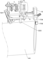
Fig. 1 is a schematic perspective view of the present invention.
Fig. 2 is a schematic perspective view of the engagement of the first gear ring and the first gear according to the present invention.
Fig. 3 is a schematic perspective view of a clamping mechanism according to the present invention.
Fig. 4 is a schematic perspective view of an unfixed steel pipe in the clamping block according to the present invention.
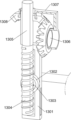
Fig. 5 is a schematic perspective view of the steel pipe of the present invention before cutting.
Fig. 6 is a schematic view of a three-dimensional structure of the steel pipe of the present invention after cutting.
Fig. 7 is a schematic perspective view of a protection mechanism of the present invention.
Fig. 8 is a schematic perspective view of an adjusting member of the present invention.
Fig. 9 is a schematic perspective view of a second spline rod, a second bevel gear, and the like according to the present invention.
Fig. 10 is a schematic perspective view of a swing assembly according to the present invention.
Fig. 11 is a schematic perspective view of the present invention.
Fig. 12 is a schematic perspective view of a separating mechanism according to the present invention.
Fig. 13 is a schematic perspective view of a sanding member in accordance with the present invention.
The reference symbols in the drawings: 1-support leg, 101-steel tube, 2-tripod, 3-connecting plate, 4-first gear ring, 5-swivel, 6-servo motor, 7-first gear, 8-slide bar, 9-U-shaped bar, 10-laser emitter, 1101-gear motor, 1102-second gear, 1103-second gear ring, 1104-first threaded bar, 1105-first spline bar, 1106-sleeve, 1107-third gear, 1108-T-block, 1109-connecting bar, 1110-clamp block, 1111-stopper plate, 1201-tension spring, 1202-L-plate, 1203-fixed block, 1301-rectangular frame, 1302-collar, 1303-spindle, 1304-reciprocating screw, 1305-second spline bar, 1306-first bevel gear, 1307-L-shaped fixed plate, 1308-second bevel gear, 1401-second, 1402-first rotating post, 1403-rotating sleeve, 1501-fixed sleeve, 1502-first spring, 1502-L-shaped bar, 1504-double arc-stopper plate, 1505-stopper plate, 1506-pressing plate, 1506-rectangular frame, 1302-third rotating block, 1703-L-shaped fixed plate, 1308-second rotating block, 1703-square frame, 1703-connecting block, 1705-rotating block, 1703-square frame.
Detailed Description
The following description of the embodiments of the present invention will be made clearly and completely with reference to the accompanying drawings, in which it is apparent that the embodiments described are only some embodiments of the present invention, but not all embodiments. All other embodiments, which can be made by those skilled in the art based on the embodiments of the invention without making any inventive effort, are intended to be within the scope of the invention.
Example 1: the pipe fitting cutting device for producing the building hanging basket comprises four supporting legs 1 which are symmetrically distributed, wherein the supporting legs 1 are provided with control terminals, the supporting legs 1 which are symmetrically distributed in the front and the back are fixedly connected with a tripod 2, the two supporting legs 1 on the left are fixedly arranged on the ground, the two supporting legs 1 on the right are slidably arranged on the ground, the two connecting plates 3 which are symmetrically distributed in the front and the back are fixedly connected on the right of the tripod 2 on the left, the two connecting plates 3 are fixedly connected with a first gear ring 4, the middle part of the first gear ring 4 is provided with a steel pipe 101, the right of the first gear ring 4 is rotationally connected with a rotating ring 5, the upper part of the inner side surface of the rotating ring 5 is fixedly connected with a servo motor 6, an output shaft of the servo motor 6 is fixedly connected with a first gear 7 meshed with the first gear ring 4, the servo motor 6 is fixedly connected with two supporting rings which are symmetrically distributed in the front and the back, the supporting rings are slidably connected with sliding rods 8, the lower part of the slide bar 8 is provided with a U-shaped bar 9, the right end of the symmetrically distributed U-shaped bar 9 is provided with a laser emitter 10 electrically connected with a control terminal, the tripod 2 is provided with a clamping mechanism for fixing the steel tube 101, the servo motor 6 is provided with a protection mechanism for keeping the distance between the laser emitter 10 and the steel tube 101, the protection mechanism comprises two tension springs 1201 which are symmetrically distributed back and forth, the two tension springs 1201 are fixedly connected between the adjacent slide bar 8 and a supporting ring of the servo motor 6 respectively, the slide bar 8 is fixedly connected with an L-shaped plate 1202, the two L-shaped plates 1202 are positioned between the two U-shaped bars 9, the lower surfaces of the two L-shaped plates 1202 are fixedly connected with a fixed block 1203, the lower side of the fixed block 1203 is provided with balls, the distance between the balls of the fixed block 1203 and the steel tube 101 is smaller than the distance between the laser emitter 10 and the steel tube 101, the distance between the laser emitter 10 and the steel tube 101 is adjusted, symmetrically distributed U-shaped rods 9 are provided with adjusting members for adjusting the position of the laser emitters 10.
As shown in fig. 1, 3 and 4, the clamping mechanism comprises a gear motor 1101, the gear motor 1101 is fixedly connected to the lower surface of a left tripod 2, an output shaft of the gear motor 1101 is fixedly connected with a second gear 1102, the left side surface of the left tripod 2 is rotationally connected with a second gear ring 1103 through a fixed ring, the tripod 2 is rotationally connected with three first threaded rods 1104 distributed at equal intervals in the circumferential direction, the first threaded rods 1104 are provided with two threads which are distributed in the bilateral symmetry and have opposite spiral directions, the right end of the left first threaded rod 1104 is fixedly connected with a first spline rod 1105, the first spline rod 1105 is provided with a sleeve 1106, the sleeve 1106 is fixedly connected with the right first threaded rod 1104, the left first threaded rod 1104 is fixedly connected with a third gear 1107 meshed with the second gear ring 1103, the inner side surface of the tripod 2 is slidingly connected with six T-shaped blocks 1108 which are distributed in the circumferential direction and symmetry, the two T-shaped blocks 1108 distributed left and right symmetrically are in threaded fit with the adjacent first threaded rods 1104, the first threaded rods 1104 rotate to drive the two T-shaped blocks 1108 to be close to each other, connecting rods 1109 are hinged to the lower portions of the symmetrically distributed T-shaped blocks 1108 respectively, the symmetrically distributed connecting rods 1109 are distributed in a crossed mode, the middle portions of the symmetrically distributed connecting rods 1109 are connected in a rotating mode, clamping blocks 1110 are hinged to the lower ends of the symmetrically distributed connecting rods 1109 respectively, the clamping blocks 1110 are made of elastic materials, one sides, close to the steel pipes 101, of the clamping blocks 1110 are arranged to be arc-shaped surfaces, contact areas between the clamping blocks 1110 and the steel pipes 101 are increased, friction force between the clamping blocks 1110 and the steel pipes 101 is improved, the follow-up steel pipe 101 cutting process is facilitated, limiting plates 1111 are fixedly connected to the clamping blocks 1110, which are far away from the first spline shafts 1105, and the limiting plates 1111 are connected in a sliding mode.
As shown in fig. 5, fig. 6 and fig. 8-fig. 10, the adjusting component comprises two rectangular frames 1301 which are symmetrically distributed from front to back, the two rectangular frames 1301 are respectively and slidably connected to the left ends of the adjacent U-shaped rods 9, one sides of the rectangular frames 1301 away from the U-shaped rods 9 are fixedly connected with a lantern ring 1302, the two lantern rings 1302 are rotatably connected with a rotating shaft 1303, the rotating shaft 1303 is in threaded fit with a reciprocating screw 1304, the reciprocating screw 1304 is positioned between the two rectangular frames 1301, the upper end of the reciprocating screw 1304 is fixedly connected with a second spline rod 1305, no spline is arranged on the upper portion of the second spline rod 1305, the sliding rod 8 is rotatably connected with the upper end of the second spline rod 1305 through a folded rod, a first bevel gear 1306 is fixedly connected with an output shaft of the servo motor 6, the first bevel gear 1306 is positioned on the left side of the first gear 7, the first bevel gear 1306 is rotatably connected with an L-shaped fixing plate 1307, the L-shaped fixing plate 1307 is rotatably connected with a second bevel gear 1308 meshed with the first bevel gear 1306, the second bevel gear 1308 is in threaded fit with the second spline rod 1305, the U-shaped rod 9 is slidably connected with the sliding rod 8, and the sliding rod 1203 is provided with a spline assembly 1203 for adjusting the angle of the rectangular frames 1301.
As shown in fig. 10, the swing assembly includes a second threaded rod 1401, the second threaded rod 1401 is in threaded connection with a fixed block 1203, a first rotating column 1402 is rotatably connected with the left end of the second threaded rod 1401, two rotating sleeves 1403 symmetrically distributed around the first rotating column 1402 are rotatably connected, the left side of each rotating sleeve 1403 is cylindrical, a rectangular frame 1301 is provided with a T-shaped groove, and each rotating sleeve 1403 is slidably connected with an adjacent T-shaped groove.
Before needing to use this cutting device to cut the steel pipe 101, the operating personnel passes two tripods 2 with the steel pipe 101 at first, and wherein the cutting place of steel pipe 101 should be located between two tripods 2 and be close to tripod 2 on right side, and the steel pipe 101 after placing is supported by eight grip blocks 1110 of downside, and steel pipe 101 is apart from four grip blocks 1110 of upside a certain distance, and then fixes steel pipe 101, and specific operation is as follows: the control terminal starts the gear motor 1101, the output shaft of the gear motor 1101 drives the second gear 1102 to rotate, the second gear 1102 drives the second gear 1103 to rotate, the second gear 1103 drives the three third gears 1107 to rotate, taking the third gear 1107 on the upper side as an example, the third gear 1107 drives the first threaded rod 1104 on the left side to rotate, the first threaded rod 1104 drives the two T-shaped blocks 1108 to be close to each other, the two T-shaped blocks 1108 drive the two clamping blocks 1110 to be close to each other and approach the steel pipe 101 through the connecting rod 1109, the first threaded rod 1104 on the left side drives the first threaded rod 1104 on the right side to rotate through the first spline rod 1105 and the sleeve 1106, the two clamping blocks 1110 on the right side are close to each other and approach the steel pipe 101, eight clamping blocks 1110 on the lower side drive the steel pipe 101 to move upwards, the steel pipe 101 is contacted with balls of the fixed block 1203, the steel pipe 101 drives the fixed block 1203 to move upwards through the balls, the fixed block 1203 drives the two L-shaped blocks 1202 to move upwards, the two L-shaped blocks 1202 drive the adjacent tension springs 1201 to move upwards respectively, the two laser beams 1201 are stretched, the two U-shaped rods 8 drive the two U-shaped rods 9 to move upwards, and the two U-shaped rods 9 always move upwards, and the distance between the two U-shaped rods 10 and the light emitters 10 are kept to move upwards.
In the process that the two slide bars 8 move upwards, the slide bar 8 on the front side drives the second spline bar 1305 to move upwards through the zigzag bar, the second spline bar 1305 drives the rotating shaft 1303 to move upwards, the rotating shaft 1303 drives the two collars 1302 to move upwards, the collars 1302 drive the rectangular frame 1301 to move upwards, the left end of the U-shaped bar 9 is always located in the middle of the rectangular frame 1301 and synchronously moves upwards, in the process that the fixing block 1203 moves upwards, the fixing block 1203 drives the second threaded rod 1401 to move upwards, the second threaded rod 1401 drives the rotating sleeve 1403 through the first rotating column 1402, the rotating sleeve 1403 moves upwards in a state of being perpendicular to the rectangular frame 1301, after a period of time, the steel pipe 101 is in contact with the four clamping blocks 1110 on the upper side, at this moment, the control terminal stops the speed reducing motor 1101, the twelve clamping blocks 1110 fix the steel pipe 101, one side of the clamping blocks 1110 close to the steel pipe 101 is an arc-shaped surface due to the fact that the clamping blocks 1110 deform to be tightly attached to the steel pipe 101, friction force between the clamping blocks 1110 and the steel pipe 101 is improved, and the fixing process of the clamping blocks 1110 is completed.
After the fixing process of the steel pipe 101 is completed, the steel pipe 101 is cut, and the specific operations are as follows: the control terminal starts the servo motor 6, the output shaft of the servo motor 6 drives the first gear 7 to rotate, the first gear 7 is meshed with the first gear ring 4 and rotates clockwise along the first gear ring 4 (right view direction), the first gear ring 4 drives the servo motor 6 and the rotary ring 5 to rotate clockwise, the servo motor 6 drives the laser emitter 10 to rotate clockwise through parts on the servo motor 6, the control terminal starts the laser emitter 10 when the servo motor 6 starts, the laser emitter 10 emits laser to gradually cut a steel tube 101 of the laser emitter, in the process of rotating the output shaft of the servo motor 6, the output shaft of the servo motor 6 drives the first bevel gear 1306 to rotate, the first bevel gear 1306 drives the reciprocating screw 1304 to rotate through the second bevel gear 1308 and the second spline rod 1305, the reciprocating screw 1304 drives the rotary shaft 1303 to move upwards, the rotary shaft 1303 drives the two lantern rings 1302 to move upwards, the two lantern rings 1302 drive the two rectangular frames 1301 to move upwards, therefore, the rectangular frames 1301 do not drive the U-shaped rod 9 to move horizontally, when the rotary ring 5 rotates clockwise by 90 degrees, the left end of the U-shaped rod 9 is located at the lower part of the adjacent rectangular frames 1301, the rectangular frames 1301 rotates clockwise, the left end of the U-shaped rod 9 rotates clockwise, the adjacent rectangular frames 1301 rotates clockwise, the rotary shaft 1301 rotates clockwise, the end of the U-shaped rod 1301 rotates clockwise, the adjacent rectangular frames around the U-shaped rod 1301 and the U-shaped rod 1301 rotates clockwise, the end around the rectangular rod 1301 when the rectangular rod 1301 and the end is located at the position of the end of the adjacent U-shaped rod 1301 and the end is turned by 180, and the end when the end is turned by 180, and the rotation is turned by 180 degrees, and the rotation is turned around, and the end is turned around and the end and is turned around.
Example 2: based on embodiment 1, as shown in fig. 11 and 12, the device further comprises a separating mechanism, the separating mechanism is arranged on a first spline rod 1105 at the upper side, the separating mechanism is used for separating the cut steel pipe 101, the separating mechanism comprises a fixed sleeve 1501, the fixed sleeve 1501 is fixedly connected to the first spline rod 1105 at the upper side, a first spring 1502 is fixedly connected between the fixed sleeve 1501 and an adjacent sleeve 1106, the first spring 1502 is in a compressed state in an initial state, the first spline rod 1105 is in sliding connection with the sleeve 1106, the first spline rod 1105 drives the sleeve 1106 to rotate, an L-shaped rod 1503 is fixedly connected to the lower surface of the fixed sleeve 1501, a double-arc-shaped baffle 1504 is rotatably connected to the right end of the L-shaped rod 1503, a torsion spring is fixedly connected between the double-arc-shaped baffle 1504 and the L-shaped rod 1503, a limiting block 1505 is fixedly connected to the sleeve 1106 at the upper side, a limiting block 1505 is fixedly connected to the left side of the lower surface of the sleeve 1106, the limiting block 1505 is matched with the upper portion of the double-arc-shaped baffle 1504, a plate 1504 is fixedly connected to the servo motor 6, the extruding plate 1504 is extruded with the lower portion of the double-arc-shaped baffle 1504, the extruding plate is extruded by the extruding plate 1504, the lower portion of the double-arc-shaped baffle 1504, the double-shaped baffle is rotatably connected to the limiting block 1505, and the double-arc-shaped baffle is used for polishing the cut light pipe 101, and the polishing part is used for polishing the limiting part 101.
As shown in fig. 13, the polishing component includes two rectangular frames 1701 symmetrically distributed around, the two rectangular frames 1701 are fixedly connected to the right side surface of the laser emitter 10, the two rectangular frames 1701 are slidably connected with a rectangular block 1702, a second spring 1703 is fixedly connected between the rectangular block 1702 and the rectangular frame 1701, the lower surface of the rectangular block 1702 is fixedly connected with a supporting rod 1704, the lower end of the supporting rod 1704 is fixedly connected with a polishing block 1705, the polishing block 1705 is provided with a ball, the left side of the polishing block 1705 is flush with the laser emitting end of the laser emitter 10, and the polishing block 1705 is flush with the right side of the cutting surface of the steel tube 101 and polishes the steel tube 101.
In the process that the swivel 5 just starts to rotate, the servo motor 6 drives the extrusion plate 1506 to rotate clockwise, the extrusion plate 1506 contacts with the lower part of the double-arc baffle 1504 and extrudes the double-arc baffle 1504, the double-arc baffle 1504 starts to rotate anticlockwise under extrusion, the torsion spring stores force, when the extrusion plate 1506 is located right below the limiting block 1505, the upper part of the double-arc baffle 1504 releases the limit of the limiting block 1505 as shown in fig. 12, but because the clamping blocks 1110 on the left side and the right side lock the steel pipe 101, and the steel pipe 101 is not cut off, the first threaded rod 1104 on the right side above cannot move rightwards, the sleeve 1106 and the limiting block 1505 cannot move rightwards, the first spring 1502 is in a compressed state, the extrusion plate 1506 gradually releases the limit of the double-arc baffle 1504 as the extrusion plate 1506 continues to rotate clockwise, when the extrusion plate 1506 does not extrude the lower part of the double-arc baffle 1504 any more, the torsion spring is reset to drive the double-arc-shaped baffle 1504 to rotate clockwise, the upper part of the double-arc-shaped baffle 1504 again limits the limiting block 1505, the limiting block 1505 cannot move rightwards, when the swivel 5 rotates 360 degrees, the extruding plate 1506 is positioned at the front side below the double-arc-shaped baffle 1504, at the moment, the steel pipe 101 is cut off, as the extruding plate 1506 continues to rotate, the extruding plate 1506 extrudes the lower side of the double-arc-shaped baffle 1504 again, the double-arc-shaped baffle 1504 releases the limiting block 1505, the first spring 1502 resets to drive the sleeve 1106 to move rightwards, the sleeve 1106 drives the first threaded rod 1104 on the right side to move rightwards, the tripod 2 on the right side and the six clamping blocks 1110 on the tripod drive the cut part on the right side of the steel pipe 101 to move rightwards, and the cut part of the steel pipe 101 breaks away from the cut part of the steel pipe 101, so that when the steel pipe 101 is about to be cut off, the steel pipe 101 is still fixed through the clamping blocks 1110 on the right side to be cut off, the cut-off part of the steel pipe 101 is pulled downwards by self gravity at the right cut-off part of the steel pipe 101, so that uneven sections appear at the cut-off part of the steel pipe 101, the cutting process of the steel pipe 101 is affected, and the cut-off part of the steel pipe 101 is separated after the steel pipe 101 is cut off, so that an operator can conveniently take down the cut-off steel pipe 101.
In the above cutting process, since the laser emitter 10 does not move laterally, the cross section of the steel pipe 101 is circular, and when it is necessary to cut the cross section of the oval steel pipe 101, the following operations are performed: before the steel pipe 101 is not fixed, an operator adjusts the deflection angle of the rectangular frame 1301, the operator rotates the second threaded rod 1401, the second threaded rod 1401 drives the first rotating column 1402 to move rightwards, the first rotating column 1402 drives the two rotating sleeves 1403 to move rightwards, the rotating sleeves 1403 drive the rectangular frame 1301 to rotate anticlockwise, when the angle rotated by the rectangular frame 1301 is identical with the deflection angle of the section ellipse, the operator stops rotating the second threaded rod 1401, the rectangular frame 1301 does not rotate any more, in the subsequent cutting process (rotating the rotating ring 5 by 90 degrees), the inclined rectangular frame 1301 moves upwards to drive the U-shaped rod 9 to move rightwards, the U-shaped rod 9 drives the laser emitter 10 to move rightwards, the U-shaped rod 9 reciprocates and transversely under the limit of the rectangular frame 1301, the U-shaped rod 9 drives the laser emitter 10 to move transversely to cut the section of the steel pipe 101 into an ellipse, and in total, by determining the deflection angle of the ellipse section of the steel pipe 101 in advance, the ellipse cutting is automatically carried out in the steel pipe 101 cutting process, and the section of the cut steel pipe 101 is ensured to be ellipse.
When the steel tube 101 moves upwards and is not in contact with the balls of the fixed block 1203, the steel tube 101 is firstly in contact with the balls on the lower side of the polishing block 1705, the left side surface of the polishing block 1705 is flush with the laser emitting end of the laser emitter 10, as shown in fig. 5, as the steel tube 101 continues to move upwards, the steel tube 101 drives the polishing block 1705 to move upwards through the balls, the polishing block 1705 drives the rectangular block 1702 to move upwards through the support rod 1704, the rectangular block 1702 moves rightwards under the limit of the rectangular block 1702, the second spring 1703 is compressed, finally, the polishing block 1705 moves rightwards while moving upwards, the laser emitter 10 is prevented from contacting the polishing block 1705 during subsequent operation, and after the polishing block 1705 moves upwards for a certain distance, the steel tube 101 contacts with the balls of the fixed block 1203. As shown in fig. 6, when the cut steel pipe 101 is not cut, the balls of the polishing block 1705 are always in contact with the steel pipe 101 (the cut steel pipe 101), the contact point is positioned on the right side of the laser emitting end of the laser emitter 10, in the process that the cut steel pipe 101 moves rightwards, the limit on the balls of the polishing block 1705 is gradually released by the cut steel pipe 101, when the cut steel pipe 101 is not in contact with the balls of the polishing block 1705 any more, the rectangular block 1702 is driven to move leftwards by the reset of the second spring 1703, the rectangular block 1702 drives the polishing block 1705 to move downwards through the supporting rod 1704, the left side face of the final polishing block 1705 is in contact with the right side face of the section of the steel pipe 101, the state is shown in fig. 6, then the section of the steel pipe 101 is continuously rubbed by the polishing block 1705 in the process that the swivel 5 continues to rotate, and the section of the steel pipe 101 is polished smoothly.
Example 3: on the basis of embodiment 2, as shown in fig. 13, the device further comprises a torsion component, the torsion component is arranged on the U-shaped rods 9, the torsion component is used for rotating the slope feet of the laser emitter 10, the laser emitter 10 is slidably connected with the right parts of the two U-shaped rods 9, the torsion component comprises a T-shaped plate 1601, the T-shaped plate 1601 is fixedly connected with the two U-shaped rods 9, the T-shaped plate 1601 is in threaded fit with a third threaded rod 1602, the right end of the third threaded rod 1602 is rotationally connected with a second rotating column 1603, the right part of the second rotating column 1603 is rotationally connected with a connecting block 1604, the laser emitter 10 is provided with a T-shaped groove, the upper part of the laser emitter 10 does not contain electrical elements, and the connecting block 1604 is slidably connected with the T-shaped groove of the laser emitter 10.
In the process of cutting the steel pipe 101, if the groove (the angle of the groove is generally 30 ° or 45 °) of the section of the steel pipe 101 needs to be adjusted, the following operations are performed: the operator rotates third threaded rod 1602, and third threaded rod 1602 drives second rotation post 1603 to move left, and second rotation post 1603 drives connecting block 1604 to move left, connecting block 1604 drives laser transmitter 10 to rotate counterclockwise, and when the angle of deflection of laser transmitter 10 is the desired groove angle, the operator stops rotating third threaded rod 1602, and laser transmitter 10 no longer rotates.
The foregoing description is only illustrative of the present invention and is not intended to limit the scope of the invention, and all equivalent structures or equivalent processes or direct or indirect application in other related arts are included in the scope of the present invention.
Claims (10)
1. A pipe fitting cutting device for production of building hanging flower basket, characterized by: comprises supporting legs (1) which are symmetrically distributed, wherein the supporting legs (1) are provided with control terminals, the supporting legs (1) which are symmetrically distributed are fixedly connected with triangular frames (2), the triangular frames (2) on one side are fixedly connected with connecting plates (3) which are symmetrically distributed, the connecting plates (3) which are symmetrically distributed are fixedly connected with first gear rings (4), the first gear rings (4) are provided with steel pipes (101), the first gear rings (4) are rotationally connected with rotating rings (5), the rotating rings (5) are fixedly connected with servo motors (6), output shafts of the servo motors (6) are fixedly connected with first gears (7) which are meshed with the first gear rings (4), the servo motors (6) are connected with symmetrically distributed sliding rods (8) through supporting rings in a sliding manner, the sliding rods (8) are provided with U-shaped rods (9), the symmetrically distributed U-shaped rods (9) are provided with laser transmitters (10) which are electrically connected with the control terminals, the triangular frames (2) are provided with clamping mechanisms which are used for fixing the steel pipes (101), the servo motors (6) are provided with protection mechanisms which are used for keeping the distance between the laser transmitters (10) and the steel pipes (101), the protection mechanisms comprise symmetrically distributed tension springs (1201), the symmetrically distributed tension springs (1201) are fixedly connected between adjacent to the sliding rods (1202) which are fixedly connected with the sliding rods (8) respectively, the L-shaped plates (1202) which are symmetrically distributed are fixedly connected with fixing blocks (1203), balls are arranged on one sides, close to the steel pipes (101), of the fixing blocks (1203), and adjusting parts for adjusting the positions of the laser transmitters (10) are arranged on the U-shaped rods (9) which are symmetrically distributed.
2. A pipe cutting apparatus for use in the production of a construction basket as claimed in claim 1, wherein: the distance from the ball of the fixed block (1203) to the steel pipe (101) is smaller than the distance from the laser transmitter (10) to the steel pipe (101).
3. A pipe cutting apparatus for use in the production of a construction basket as claimed in claim 1, wherein: the clamping mechanism comprises a gear motor (1101), the gear motor (1101) is fixedly connected to a tripod (2) close to a first gear ring (4), a second gear (1102) is fixedly connected to an output shaft of the gear motor (1101), the tripod (2) close to the first gear ring (4) is rotationally connected with a second gear ring (1103) through a fixed ring, the tripod (2) is rotationally connected with first threaded rods (1104) distributed at equal intervals in the circumferential direction, the first threaded rods (1104) are provided with threads which are symmetrically distributed and have opposite spiral directions, first threaded rods (1104) close to the first gear ring (4) are fixedly connected with first spline rods (1105), the first spline rods (1105) are provided with sleeves (1106), the sleeves (1106) are fixedly connected with the first threaded rods (1104) adjacent and far away from the first gear ring (4), the first threaded rods (1104) close to the first gear ring (4) are fixedly connected with third gears (1107) meshed with the second gear ring (1103), the tripod (2) is slidingly connected with T-shaped blocks (1108) distributed in the circumferential direction at equal intervals, the T-shaped blocks (1108) distributed in the circumferential direction are symmetrically, the T-shaped blocks (1108) are matched with the adjacent first threaded rods (1110) in the circumferential direction, the T-shaped blocks (1108) distributed symmetrically are symmetrically, the T-shaped blocks (1108) distributed symmetrically are in the sliding mode, the T-shaped blocks (1108) are symmetrically distributed symmetrically (1109) and are in a matched mode, the symmetrically-shaped connecting rods (1109) are symmetrically distributed, and are in a mode, and the symmetrically-shaped connecting rods (1109 are respectively, the clamping block (1110) close to the first spline rod (1105) is fixedly connected with a limiting plate (1111), and the clamping block (1110) far away from the first spline rod (1105) is in sliding connection with the limiting plate (1111).
4. A pipe cutting apparatus for use in the production of a construction basket according to claim 3, wherein: the clamping block (1110) is made of elastic materials, and one side, close to the steel pipe (101), of the clamping block (1110) is provided with an arc-shaped surface for increasing the contact area between the clamping block (1110) and the steel pipe (101).
5. A pipe cutting apparatus for use in the production of a construction basket as claimed in claim 1, wherein: the adjusting part comprises rectangular frames (1301) which are symmetrically distributed, the rectangular frames (1301) which are symmetrically distributed are respectively and slidably connected with adjacent U-shaped rods (9), lantern rings (1302) are fixedly connected with the rectangular frames (1301), the lantern rings (1302) which are symmetrically distributed are rotationally connected with rotating shafts (1303), the rotating shafts (1303) are in threaded fit with reciprocating screw rods (1304), the reciprocating screw rods (1304) are fixedly connected with second spline rods (1305), sliding rods (8) are rotationally connected with the second spline rods (1305) through the folded rods, output shafts of servo motors (6) are fixedly connected with first bevel gears (1306), the first bevel gears (1306) are rotationally connected with L-shaped fixing plates (1307), the L-shaped fixing plates (1307) are rotationally connected with second bevel gears (1308) which are meshed with the first bevel gears (1306), the second bevel gears (1308) are in spline fit with the second spline rods (1305), the U-shaped rods (9) are slidably connected with the sliding rods (1305), and the fixing blocks (1203) are provided with swinging components which are used for adjusting the deflection angles of the rectangular frames (1301).
6. A pipe cutting apparatus for use in the production of a construction basket as claimed in claim 5, wherein: the swing assembly comprises a second threaded rod (1401), the second threaded rod (1401) is in threaded connection with a fixed block (1203), the second threaded rod (1401) is rotationally connected with a first rotating column (1402), the first rotating column (1402) is rotationally connected with symmetrically distributed rotating sleeves (1403), a rectangular frame (1301) is provided with T-shaped grooves, and the rotating sleeves (1403) are in sliding connection with adjacent T-shaped grooves.
7. A pipe cutting apparatus for use in the production of a construction basket according to claim 3, wherein: still including separating mechanism, separating mechanism sets up in being close to first spline pole (1105) of servo motor (6), separating mechanism is used for separating steel pipe (101) after the cutting, separating mechanism is including fixed cover (1501), fixed cover (1501) rigid coupling is in being close to first spline pole (1105) of servo motor (6), the rigid coupling has first spring (1502) between fixed cover (1501) and the adjacent sleeve (1106), first spline pole (1105) and sleeve (1106) sliding connection, fixed cover (1501) rigid coupling has L shape pole (1503), L shape pole (1503) rotate and are connected with double-arc baffle (1504), rigid coupling has the torsional spring between double-arc baffle (1504) and the L shape pole (1503), sleeve (1106) rigid coupling that is close to servo motor (6) has stopper (1505), servo motor (6) rigid coupling has extrusion board (1506) with double-arc baffle (1504) complex, laser emitter (10) are provided with the part of polishing that is used for polishing steel pipe (101) cutting face.
8. A pipe cutting apparatus for use in the production of a construction basket as claimed in claim 7, wherein: the polishing component comprises symmetrically distributed rectangular frames (1701), wherein the symmetrically distributed rectangular frames (1701) are fixedly connected to the laser transmitters (10), rectangular blocks (1702) are slidably connected to the symmetrically distributed rectangular frames (1701), second springs (1703) are fixedly connected between the rectangular blocks (1702) and the rectangular frames (1701), polishing blocks (1705) are fixedly connected to the rectangular blocks (1702) through supporting rods (1704), and balls are arranged on the polishing blocks (1705).
9. A pipe cutting apparatus for use in the production of a construction basket as claimed in claim 8, wherein: one side of the grinding block (1705) close to the servo motor (6) is flush with the laser emitting end of the laser emitter (10).
10. A pipe cutting apparatus for use in the production of a construction basket as claimed in claim 1, wherein: still including torsion subassembly, torsion subassembly sets up in U-shaped pole (9), torsion subassembly is used for rotating the toe of laser emitter (10), laser emitter (10) are connected with symmetrical distribution's U-shaped pole (9) rotation, torsion subassembly is including T shaped plate (1601), T shaped plate (1601) rigid coupling is in symmetrical distribution's U-shaped pole (9), T shaped plate (1601) screw-thread fit has third threaded rod (1602), third threaded rod (1602) rotate and are connected with second rotation post (1603), second rotation post (1603) rotate and are connected with connecting block (1604), laser emitter (10) are provided with the T-shaped groove, T-shaped groove sliding connection of connecting block (1604) and laser emitter (10).
Priority Applications (1)
| Application Number | Priority Date | Filing Date | Title |
|---|---|---|---|
| CN202310685609.6A CN116423068B (en) | 2023-06-12 | 2023-06-12 | Pipe fitting cutting device for production of building hanging basket |
Applications Claiming Priority (1)
| Application Number | Priority Date | Filing Date | Title |
|---|---|---|---|
| CN202310685609.6A CN116423068B (en) | 2023-06-12 | 2023-06-12 | Pipe fitting cutting device for production of building hanging basket |
Publications (2)
| Publication Number | Publication Date |
|---|---|
| CN116423068A true CN116423068A (en) | 2023-07-14 |
| CN116423068B CN116423068B (en) | 2023-08-18 |
Family
ID=87087546
Family Applications (1)
| Application Number | Title | Priority Date | Filing Date |
|---|---|---|---|
| CN202310685609.6A Active CN116423068B (en) | 2023-06-12 | 2023-06-12 | Pipe fitting cutting device for production of building hanging basket |
Country Status (1)
| Country | Link |
|---|---|
| CN (1) | CN116423068B (en) |
Cited By (4)
| Publication number | Priority date | Publication date | Assignee | Title |
|---|---|---|---|---|
| CN116914618A (en) * | 2023-07-27 | 2023-10-20 | 哈沈线缆制造有限公司 | End face-flattened cutting device for cable processing |
| CN117444528A (en) * | 2023-12-21 | 2024-01-26 | 合一(广州)文化发展有限公司 | Street lamp pole welding fixture |
| CN118162775A (en) * | 2024-05-13 | 2024-06-11 | 大连理工高邮研究院有限公司 | Laser cutting device for manufacturing high-end equipment |
| CN118492494A (en) * | 2024-07-19 | 2024-08-16 | 江苏天辉环保科技有限公司 | Multi-size thermal power is with wear-resisting pipeline production equipment of cuting |
Citations (11)
| Publication number | Priority date | Publication date | Assignee | Title |
|---|---|---|---|---|
| EP0983819A1 (en) * | 1998-08-31 | 2000-03-08 | Walter Gensabella | Device for laser cutting of profiled pipes |
| CN201792126U (en) * | 2010-09-27 | 2011-04-13 | 无锡华联科技集团有限公司 | Five-axis steel pipe intersecting line cutting machine |
| CN102806404A (en) * | 2012-09-04 | 2012-12-05 | 山东豪迈机械制造有限公司 | Pipe intersection line cutting device |
| CN205764672U (en) * | 2016-05-16 | 2016-12-07 | 天津市华彪金属制品有限公司 | Interior pipe clamp |
| US9682448B1 (en) * | 2015-03-12 | 2017-06-20 | Vincent P. Cassarino | Apparatus for torch cutting large pipe |
| CN210209166U (en) * | 2019-05-16 | 2020-03-31 | 凯沃智能装备(青岛)有限公司 | Multi-station interconnected welding robot operating platform |
| CN216055668U (en) * | 2021-11-01 | 2022-03-15 | 富通尼科技(苏州)有限公司 | Detachable high-power infrared picosecond laser |
| CN114406544A (en) * | 2022-02-10 | 2022-04-29 | 深圳盟豪机械制造有限公司 | Pipeline all-position automatic welding machine |
| CN216462655U (en) * | 2021-11-04 | 2022-05-10 | 云南丰普科技有限公司 | Horizontal automatic profiling welding equipment |
| CN217343879U (en) * | 2022-03-24 | 2022-09-02 | 莱阳中平汽车配件有限公司 | Novel inner gear ring automatic positioning and clamping mechanism |
| CN115446904A (en) * | 2022-10-27 | 2022-12-09 | 济南鼎点数控设备有限公司 | Numerical control carbon fiber pipeline cutting machine and circular cutting method thereof |
-
2023
- 2023-06-12 CN CN202310685609.6A patent/CN116423068B/en active Active
Patent Citations (11)
| Publication number | Priority date | Publication date | Assignee | Title |
|---|---|---|---|---|
| EP0983819A1 (en) * | 1998-08-31 | 2000-03-08 | Walter Gensabella | Device for laser cutting of profiled pipes |
| CN201792126U (en) * | 2010-09-27 | 2011-04-13 | 无锡华联科技集团有限公司 | Five-axis steel pipe intersecting line cutting machine |
| CN102806404A (en) * | 2012-09-04 | 2012-12-05 | 山东豪迈机械制造有限公司 | Pipe intersection line cutting device |
| US9682448B1 (en) * | 2015-03-12 | 2017-06-20 | Vincent P. Cassarino | Apparatus for torch cutting large pipe |
| CN205764672U (en) * | 2016-05-16 | 2016-12-07 | 天津市华彪金属制品有限公司 | Interior pipe clamp |
| CN210209166U (en) * | 2019-05-16 | 2020-03-31 | 凯沃智能装备(青岛)有限公司 | Multi-station interconnected welding robot operating platform |
| CN216055668U (en) * | 2021-11-01 | 2022-03-15 | 富通尼科技(苏州)有限公司 | Detachable high-power infrared picosecond laser |
| CN216462655U (en) * | 2021-11-04 | 2022-05-10 | 云南丰普科技有限公司 | Horizontal automatic profiling welding equipment |
| CN114406544A (en) * | 2022-02-10 | 2022-04-29 | 深圳盟豪机械制造有限公司 | Pipeline all-position automatic welding machine |
| CN217343879U (en) * | 2022-03-24 | 2022-09-02 | 莱阳中平汽车配件有限公司 | Novel inner gear ring automatic positioning and clamping mechanism |
| CN115446904A (en) * | 2022-10-27 | 2022-12-09 | 济南鼎点数控设备有限公司 | Numerical control carbon fiber pipeline cutting machine and circular cutting method thereof |
Cited By (6)
| Publication number | Priority date | Publication date | Assignee | Title |
|---|---|---|---|---|
| CN116914618A (en) * | 2023-07-27 | 2023-10-20 | 哈沈线缆制造有限公司 | End face-flattened cutting device for cable processing |
| CN116914618B (en) * | 2023-07-27 | 2024-02-02 | 哈沈线缆制造有限公司 | End face-flattened cutting device for cable processing |
| CN117444528A (en) * | 2023-12-21 | 2024-01-26 | 合一(广州)文化发展有限公司 | Street lamp pole welding fixture |
| CN118162775A (en) * | 2024-05-13 | 2024-06-11 | 大连理工高邮研究院有限公司 | Laser cutting device for manufacturing high-end equipment |
| CN118162775B (en) * | 2024-05-13 | 2024-08-23 | 大连理工高邮研究院有限公司 | Laser cutting device for manufacturing high-end equipment |
| CN118492494A (en) * | 2024-07-19 | 2024-08-16 | 江苏天辉环保科技有限公司 | Multi-size thermal power is with wear-resisting pipeline production equipment of cuting |
Also Published As
| Publication number | Publication date |
|---|---|
| CN116423068B (en) | 2023-08-18 |
Similar Documents
| Publication | Publication Date | Title |
|---|---|---|
| CN116423068B (en) | Pipe fitting cutting device for production of building hanging basket | |
| WO2024021288A1 (en) | Pipeline construction apparatus | |
| CN109648409B (en) | Clamping and feeding mechanism for adjusting cylindricity of semiconductor silicon rod | |
| CN108222478B (en) | Building support auxiliary assembly capable of realizing directional conversion | |
| CN109531027B (en) | Welding machine for gas filling bottle | |
| CN111468773B (en) | Pipe building material processing apparatus for building engineering | |
| CN113399908B (en) | A pipeline subassembly fixed equipment for steel construction truss | |
| CN113053591A (en) | Cable roundness shaping and positioning device | |
| CN110051981A (en) | Ligament tensioner | |
| CN109483140A (en) | A kind of electric power tower welding rotary table | |
| CN114700732A (en) | Pipeline welding all-in-one of polishing | |
| CN110605757B (en) | Cutting machine for building with angle modulation function | |
| CN211203332U (en) | Novel support frame for hydraulic engineering measurement | |
| CN112179786A (en) | Irrigation and drainage pipe detection device | |
| CN216276757U (en) | Angle-adjustable protection device for building construction | |
| CN212948093U (en) | A stabilize cutting device for hydraulic engineering pipe | |
| CN113551125A (en) | But high definition laser projector of angular rotation adjustment | |
| CN110394506A (en) | A kind of square tube processing unit (plant) | |
| CN210397476U (en) | Transmission shaft for industrial robot | |
| CN219380159U (en) | Incision grinding device is used in PE tubular product processing | |
| CN219287112U (en) | Electric device with adjustable direction and angle of electric wire | |
| CN206306283U (en) | A kind of mill colloid cutting mechanism | |
| CN218791536U (en) | Platform is placed with equipment to mechanical equipment sale | |
| CN112025453B (en) | Internal chamfering polishing equipment for non-standard plum blossom snap ring | |
| CN219569701U (en) | Steel structure support column with adjustable constructional engineering angle |
Legal Events
| Date | Code | Title | Description |
|---|---|---|---|
| PB01 | Publication | ||
| PB01 | Publication | ||
| SE01 | Entry into force of request for substantive examination | ||
| SE01 | Entry into force of request for substantive examination | ||
| GR01 | Patent grant | ||
| GR01 | Patent grant |