CN211203332U - Novel support frame for hydraulic engineering measurement - Google Patents
Novel support frame for hydraulic engineering measurement Download PDFInfo
- Publication number
- CN211203332U CN211203332U CN201921143210.0U CN201921143210U CN211203332U CN 211203332 U CN211203332 U CN 211203332U CN 201921143210 U CN201921143210 U CN 201921143210U CN 211203332 U CN211203332 U CN 211203332U
- Authority
- CN
- China
- Prior art keywords
- support frame
- hydraulic engineering
- spring
- bearing
- novel support
- Prior art date
- Legal status (The legal status is an assumption and is not a legal conclusion. Google has not performed a legal analysis and makes no representation as to the accuracy of the status listed.)
- Active
Links
Images


Landscapes
- A Measuring Device Byusing Mechanical Method (AREA)
Abstract
The utility model discloses a novel support frame for hydraulic engineering measurement relates to support frame technical field, and it includes a shell section of thick bamboo, the quantity of a shell section of thick bamboo is three, be provided with the stabilizer blade in the shell section of thick bamboo, a plurality of draw-in groove has been seted up to the left surface of stabilizer blade, and is provided with the cardboard in one of them draw-in groove. This novel support frame for hydraulic engineering is measured, through lug, the slide bar, first spring, the slide bar, first bearing, the cardboard, the draw-in groove, the stabilizer blade, the apparatus further comprises a rotating shaft, mutually support between the second bearing, not only can carry out height control's work according to the condition of relief, can also carry out diversified angular adjustment's work according to the actual demand, and do not need staff's equipment and dismantlement, can contract promptly and the work of accomodating, and then be favorable to carrying of staff, made things convenient for staff's work, also ensured the utility model discloses a good result of use to staff's facilitate the use has further been guaranteed.
Description
Technical Field
The utility model relates to a support frame technical field specifically is a novel support frame for hydraulic engineering is measured.
Background
Hydraulic engineering is at the in-process of construction, measuring instrument can be used usually, and measuring instrument also can use through the cooperation of support frame, but traditional support frame is mostly assembled, need the staff to assemble and erect measuring instrument, and then when not using, still need dismantle, can not stretch out and draw back and the work of accomodating on original basis, be unfavorable for staff's the work of carrying, thereby bring certain trouble for staff's work, and still can not carry out better adjustment according to the condition of topography and use, can not adjust the angle of support frame from a plurality of positions according to actual demand simultaneously, not only can not ensure the good result of use of support frame, staff's facilitate the use has still been influenced, therefore, an urgent need has a support frame for the engineering measurement of having multi-functional advantage.
SUMMERY OF THE UTILITY MODEL
Technical problem to be solved
The utility model is not enough to prior art, the utility model provides a novel support frame for hydraulic engineering is measured, it is mostly assembled to have solved traditional support frame, need the staff to assemble and erect measuring instrument, and then when not using, still need dismantle, can not stretch out and draw back and the work of accomodating on original basis, be unfavorable for staff's the work of carrying, thereby bring certain trouble for staff's work, and still can not carry out better adjustment according to the condition of relief and use, can not adjust the angle of support frame from a plurality of positions according to actual demand simultaneously, not only can not ensure the good result of use of support frame, staff's the problem of facilitating the use has still been influenced.
(II) technical scheme
In order to achieve the above purpose, the utility model adopts the technical proposal that: the utility model provides a novel support frame for hydraulic engineering is measured, includes a shell section of thick bamboo, the quantity of a shell section of thick bamboo is three, be provided with the stabilizer blade in the shell section of thick bamboo, a plurality of draw-in groove has been seted up to the left surface of stabilizer blade, and is provided with the cardboard in one of them draw-in groove, the left surface fixedly connected with slide bar of cardboard, the slide bar cup joints in the sliding sleeve, the sliding sleeve joint is in first bearing, first bearing joint is in a shell section of thick bamboo, the right flank fixed connection of first spring and thrust unit is passed through to the left surface of sliding sleeve.
Thrust unit fixed connection is at the left end of slide bar, first spring cup joints outside the slide bar, a shell section of thick bamboo is through round pin axle and fixed block swing joint, and the equal fixed connection of three fixed block at the backup pad lower surface, the upper surface of backup pad passes through the lower fixed surface who rotates device and supporting seat and is connected, two connecting plates of the last fixed surface of supporting seat are connected, the right flank of connecting plate is through the left surface fixed connection of two telescoping devices and a limiting plate.
Preferably, the pushing device comprises a limiting block, the right side face of the limiting block is fixedly connected with the left ends of the first spring and the sliding rod respectively, and a convex block is arranged on the left side face of the limiting block.
Preferably, rotating device includes the second bearing, the upper surface at the backup pad of second bearing joint, the pivot has been cup jointed in the second bearing, pivot fixed connection is at the lower surface of supporting seat.
Preferably, the telescopic device comprises a telescopic rod, a second spring is sleeved on the outer surface of the telescopic rod, and the left end and the right end of the second spring and the telescopic rod are fixedly connected with the right side face of the connecting plate and the left side face of the limiting plate respectively.
Preferably, a plurality of grooves are formed in the lower surface of the supporting seat, a threaded rod is arranged in one groove, the threaded rod is connected in a threaded cap in a threaded mode, and the threaded cap is arranged on the left side face of the fixing plate.
Preferably, the lower surface of the fixing plate is fixedly connected with the upper surface of the supporting plate, the bottom end of the threaded rod is fixedly connected with the upper surface of the knob, and a rubber sleeve is arranged on the outer surface of the knob.
(III) advantageous effects
The beneficial effects of the utility model reside in that:
1. the novel support frame for hydraulic engineering measurement comprises a lug, a slide rod, a first spring, the slide rod, a first bearing, a clamping plate, a clamping groove, a supporting leg, a rotating shaft and a second bearing which are mutually matched, when the height needs to be adjusted, a worker can hold the lug and rotate in the first bearing through the slide sleeve, so as to drive the slide rod and the clamping plate to rotate, when rotating for ninety degrees, the clamping plate corresponds to the outlet position of the clamping groove, at the moment, the first spring drives the clamping plate to move leftwards through the slide rod by utilizing the elasticity of the first spring, so that the clamping plate is separated from the clamping groove, then the supporting leg is pulled downwards, when the supporting leg moves to a proper position, the lug is pressed rightwards, so that the lug extrudes the first spring, the clamping plate is driven to enter the clamping groove through the slide rod, then the lug rotates for ninety degrees through the rotation in the, when the angle needs to be adjusted, the threaded rod is rotated by the knob to rotate out of the groove, then the threaded rod rotates in the second bearing through the rotating shaft, the supporting seat rotates, when the angle is proper, the threaded rod is rotated into the groove by rotating the knob, when the threaded rod needs to be stored, a worker holds the lug and rotates in the first bearing through the sliding sleeve to drive the sliding rod and the clamping plate to rotate, when the threaded rod rotates ninety degrees, the clamping plate corresponds to the outlet position of the clamping groove, at the moment, the first spring drives the clamping plate to move leftwards through the sliding rod by utilizing the elasticity of the first spring, the clamping plate is separated from the clamping groove, then the supporting leg is pulled upwards, when the threaded rod moves to the proper position, the lug is pressed rightwards to extrude the first spring, the clamping plate is driven into the clamping groove through the sliding rod, and then the clamping sleeve rotates the, and then make the lug pass through the slide bar and drive in the cardboard card goes into the draw-in groove to accomplish the completion of height and accomodating and angular adjustment work through above-mentioned operation, not only can carry out height adjustment's work according to the condition of relief, can also carry out diversified angular adjustment's work according to the actual demand, do not need staff's equipment and dismantlement moreover, can contract promptly and the work of accomodating, and then be favorable to carrying of staff, made things convenient for staff's work, also ensured the utility model discloses a good result of use to staff's facilitate the use has further been guaranteed.
2. This novel support frame for hydraulic engineering is measured through mutually supporting between second spring and the limiting plate for staff's accessible second spring is to the extrusion of limiting plate, and then fixes the measuring instrument body, has not only guaranteed firm effect, still makes through extrudeing the second spring, can realize placing not the measuring instrument of equidimension, has improved its practicality.
3. This novel support frame for hydraulic engineering is measured through mutually supporting between knob and the threaded rod, through rotatory knob for in the knob drives the threaded rod and changes over to the recess, and then fixed to the supporting seat, avoided the supporting seat to take place the displacement of angle, thereby can ensure the more accurate measurement work of staff.
Drawings
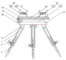
Fig. 1 is a schematic front view of a cross-sectional structure of the present invention;
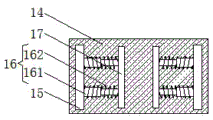
FIG. 2 is a schematic structural view of the connection plate of the present invention viewed from above;
fig. 3 is an enlarged schematic structural view at a position a of the present invention;
fig. 4 is an enlarged schematic structural diagram of the position B of the present invention.
In the figure: the device comprises a shell 1, a supporting leg 2, a clamping groove 3, a clamping plate 4, a sliding rod 5, a sliding sleeve 6, a first bearing 7, a pushing device 8, a limiting block 81, a convex block 82, a first spring 9, a pin shaft 10, a fixed block 11, a supporting plate 12, a rotating device 13, a second bearing 131, a rotating shaft 132, a supporting seat 14, a connecting plate 15, a telescopic device 16, a telescopic rod 161, a second spring 162, a limiting plate 17, a groove 18, a threaded rod 19, a threaded cap 20, a knob 21 and a fixed plate 22.
Detailed Description
The technical solutions in the embodiments of the present invention will be described clearly and completely with reference to the accompanying drawings in the embodiments of the present invention, and it is obvious that the described embodiments are only some embodiments of the present invention, not all embodiments. Based on the embodiments in the present invention, all other embodiments obtained by a person skilled in the art without creative work belong to the protection scope of the present invention.
As shown in fig. 1-4, the utility model provides a technical solution: a novel support frame for hydraulic engineering measurement comprises a shell 1, wherein the number of the shell 1 is three, support legs 2 are arranged in the shell 1, a plurality of clamping grooves 3 are formed in the left side surfaces of the support legs 2, a clamping plate 4 is arranged in one of the clamping grooves 3, a sliding rod 5 is fixedly connected to the left side surface of the clamping plate 4, the sliding rod 5 is sleeved in a sliding sleeve 6, the sliding rod 5 can effectively slide in the sliding sleeve 6 by arranging the sliding sleeve 6, the condition that the sliding rod 5 inclines is avoided, the sliding rod 5 can be ensured to drive the clamping plate 4 to accurately enter the clamping grooves 3, the sliding sleeve 6 is clamped in a first bearing 7, the first bearing 7 is clamped in the shell 1, the left side surface of the sliding sleeve 6 is fixedly connected with the right side surface of a pushing device 8 through a first spring 9, the pushing device 8 comprises a limiting block 81, the right side surface of the limiting block 81 is fixedly connected with the first spring 9 and, the left side of stopper 81 is provided with lug 82, through setting up lug 82, and the surface of lug 82 is provided with anti-skidding line for staff's palm and lug 82's frictional force increase, thereby make things convenient for staff's control to lug 82 more.
The pushing device 8 is fixedly connected at the left end of the sliding rod 5, the first spring 9 is sleeved outside the sliding rod 5, the shell barrel 1 is movably connected with the fixed blocks 11 through the pin shaft 10, the three fixed blocks 11 are all fixedly connected with the lower surface of the supporting plate 12, the upper surface of the supporting plate 12 is fixedly connected with the lower surface of the supporting seat 14 through the rotating device 13, the lower surface of the supporting seat 14 is provided with a plurality of grooves 18, through the arrangement of the plurality of grooves 18, when a worker rotates at different angles, the supporting seat 14 can be fixed through one of the grooves 18, so that the fixing work of multiple angles is convenient to carry out, in addition, the threaded rod 19 is arranged in one of the grooves 18, the threaded rod 19 is in the threaded cap 20 in a threaded manner, through the arrangement of the threaded cap 20, the threaded rod 19 can rotate under the threaded connection effect of the threaded, the screw cap 20 is arranged on the left side surface of the fixing plate 22, the lower surface of the fixing plate 22 is fixedly connected with the upper surface of the supporting plate 12, the bottom end of the threaded rod 19 is fixedly connected with the upper surface of the knob 21, the rubber sleeve is arranged on the outer surface of the knob 21, the rubber sleeve has certain flexibility, the friction force between the palm of a worker and the rubber sleeve is increased, certain comfort can be provided for the worker, the worker can work more conveniently, the knob 21 is matched with the threaded rod 19 through the knob 21, the knob 21 drives the threaded rod 19 to rotate into the groove 18 through rotation of the knob 21, the supporting seat 14 is fixed, the displacement of the supporting seat 14 caused by an angle is avoided, the accurate measurement work of the worker can be guaranteed, the rotating device 13 comprises a second bearing 131, and the second bearing 131 is clamped on the upper surface of the supporting plate 12, the rotating shaft 132 is sleeved in the second bearing 131, the rotating shaft 132 can rotate in the second bearing 131 by arranging the second bearing 131 and the rotating shaft 132, so that the supporting seat 14 can rotate through the rotating shaft 132, and the work of adjusting the angle of the supporting seat 14 can be ensured, the rotating shaft 132 is fixedly connected to the lower surface of the supporting seat 14, the upper surface of the supporting seat 14 is fixedly connected with two connecting plates 15, the right side surface of each connecting plate 15 is fixedly connected with the left side surface of one limiting plate 17 through two telescopic devices 16, each telescopic device 16 comprises a telescopic rod 161, and by arranging the telescopic rods 161, the telescopic rods 161 can be driven to stretch when the second spring 162 stretches, so that the telescopic rods 161 can ensure the horizontality of the force of the second spring 162, the force inclination is avoided, the work of the second spring 162 can be better ensured, the second spring 162 is sleeved on the outer surface of, through mutually supporting between second spring 162 and the limiting plate 17 for staff's accessible second spring 162 extrudees the limiting plate 17, and then fixes the measuring instrument body, has not only guaranteed firm effect, still makes through extrudeing second spring 162, can realize placing the measuring instrument of equidimension not, has improved its practicality, both ends respectively with the right flank of connecting plate 15 and the left surface fixed connection of limiting plate 17 about second spring 162 and telescopic link 161.
The utility model discloses an operating procedure does:
s1, when the height needs to be adjusted, a worker can hold the lug 82 and rotate in the first bearing 7 through the sliding sleeve 6, and further drive the sliding rod 5 and the clamping plate 4 to rotate, when the height needs to be adjusted by ninety degrees, the clamping plate 4 corresponds to the outlet position of the clamping groove 3, at this time, the first spring 9 utilizes the elasticity of the first spring to drive the clamping plate 4 to move leftwards through the sliding rod 5, so that the clamping plate 4 is separated from the clamping groove 3, then the supporting leg 2 is pulled downwards, when the supporting leg 2 moves to a proper position, the lug 82 is pressed rightwards, so that the lug 82 extrudes the first spring 9, the clamping plate 4 is driven to enter the clamping groove 3 through the sliding rod 5, then the lug 82 rotates by ninety degrees in the first bearing 7 through the rotation of the sliding sleeve 6, and further the lug 82 drives;
s2, when the angle needs to be adjusted, the threaded rod 19 is rotated through the knob 21, so that the threaded rod 19 rotates out of the groove 18, then the rotating shaft 132 rotates in the second bearing 131, so that the supporting seat 14 rotates, and when the angle is appropriate, the threaded rod 19 rotates into the groove 18 through the rotation of the knob 21;
s3, when needing to accomodate, the staff holds lug 82 and rotates in first bearing 7 through sliding sleeve 6, and then drive slide bar 5 and cardboard 4 and rotate, when rotatory ninety degrees, make cardboard 4 corresponding with the exit position of draw-in groove 3, at this moment first spring 9 utilizes self elasticity to pass through slide bar 5 and drive cardboard 4 and move left, make cardboard 4 break away from draw-in groove 3, then upwards stimulate stabilizer blade 2, when moving to suitable position, press lug 82 right, make lug 82 extrude first spring 9, and drive cardboard 4 through slide bar 5 and get into draw-in groove 3, then rethread sliding sleeve 6 rotates ninety degrees lug 82 in first bearing 7, and then make lug 82 drive cardboard 4 through slide bar 5 and block in draw-in groove 3, thereby through the completion of above-mentioned operation completion of height and accomodating and angle adjustment work.
The above-mentioned embodiments further describe the objects, technical solutions and advantages of the present invention in detail, it should be understood that the above description is only the embodiments of the present invention, and is not intended to limit the present invention, and any modifications, equivalent substitutions, improvements and the like made within the spirit and principle of the present invention should be included in the scope of the present invention.
Claims (6)
1. The utility model provides a novel support frame for hydraulic engineering is measured, includes shell section of thick bamboo (1), its characterized in that: the number of the shell barrels (1) is three, the support legs (2) are arranged in the shell barrels (1), a plurality of clamping grooves (3) are formed in the left side faces of the support legs (2), a clamping plate (4) is arranged in one clamping groove (3), a sliding rod (5) is fixedly connected to the left side face of the clamping plate (4), the sliding rod (5) is sleeved in a sliding sleeve (6), the sliding sleeve (6) is clamped in a first bearing (7), the first bearing (7) is clamped in the shell barrel (1), and the left side face of the sliding sleeve (6) is fixedly connected with the right side face of a pushing device (8) through a first spring (9);
thrust unit (8) fixed connection is at the left end of slide bar (5), cup joint outside slide bar (5) first spring (9), shell section of thick bamboo (1) is through round pin axle (10) and fixed block (11) swing joint, and the equal fixed connection of three fixed block (11) is at backup pad (12) lower surface, the upper surface of backup pad (12) passes through the fixed surface connection of rotating device (13) and supporting seat (14), the last fixed surface of supporting seat (14) is connected with two connecting plates (15), the right flank of connecting plate (15) is through the left surface fixed connection of two telescoping device (16) and a limiting plate (17).
2. The novel support frame for hydraulic engineering measurement of claim 1, characterized in that: the pushing device (8) comprises a limiting block (81), the right side face of the limiting block (81) is fixedly connected with the left ends of the first spring (9) and the sliding rod (5) respectively, and a convex block (82) is arranged on the left side face of the limiting block (81).
3. The novel support frame for hydraulic engineering measurement of claim 1, characterized in that: rotating device (13) include second bearing (131), second bearing (131) joint is at the upper surface of backup pad (12), pivot (132) have been cup jointed in second bearing (131), pivot (132) fixed connection is at the lower surface of supporting seat (14).
4. The novel support frame for hydraulic engineering measurement of claim 1, characterized in that: telescoping device (16) includes telescopic link (161), second spring (162) have been cup jointed to the surface of telescopic link (161), both ends respectively with the right flank of connecting plate (15) and the left surface fixed connection of limiting plate (17) about second spring (162) and telescopic link (161).
5. The novel support frame for hydraulic engineering measurement of claim 1, characterized in that: the lower surface of the supporting seat (14) is provided with a plurality of grooves (18), a threaded rod (19) is arranged in one groove (18), the threaded rod (19) is connected in a threaded cap (20) in a threaded mode, and the threaded cap (20) is arranged on the left side face of a fixing plate (22).
6. The novel support frame for hydraulic engineering measurement of claim 5, characterized in that: the lower surface of fixed plate (22) and the last fixed surface of backup pad (12) are connected, the bottom of threaded rod (19) and the last fixed surface of knob (21) are connected, the surface of knob (21) is provided with the rubber sleeve.
Priority Applications (1)
| Application Number | Priority Date | Filing Date | Title |
|---|---|---|---|
| CN201921143210.0U CN211203332U (en) | 2019-07-20 | 2019-07-20 | Novel support frame for hydraulic engineering measurement |
Applications Claiming Priority (1)
| Application Number | Priority Date | Filing Date | Title |
|---|---|---|---|
| CN201921143210.0U CN211203332U (en) | 2019-07-20 | 2019-07-20 | Novel support frame for hydraulic engineering measurement |
Publications (1)
| Publication Number | Publication Date |
|---|---|
| CN211203332U true CN211203332U (en) | 2020-08-07 |
Family
ID=71887248
Family Applications (1)
| Application Number | Title | Priority Date | Filing Date |
|---|---|---|---|
| CN201921143210.0U Active CN211203332U (en) | 2019-07-20 | 2019-07-20 | Novel support frame for hydraulic engineering measurement |
Country Status (1)
| Country | Link |
|---|---|
| CN (1) | CN211203332U (en) |
Cited By (2)
| Publication number | Priority date | Publication date | Assignee | Title |
|---|---|---|---|---|
| CN114857416A (en) * | 2021-02-03 | 2022-08-05 | 艾极倍特(上海)半导体设备有限公司 | Camera offset support convenient to adjust and use method thereof |
| CN116140825A (en) * | 2022-12-19 | 2023-05-23 | 江苏郎克斯智能工业科技有限公司 | Fine trimming device for manufacturing precision forging parts and use process thereof |
-
2019
- 2019-07-20 CN CN201921143210.0U patent/CN211203332U/en active Active
Cited By (2)
| Publication number | Priority date | Publication date | Assignee | Title |
|---|---|---|---|---|
| CN114857416A (en) * | 2021-02-03 | 2022-08-05 | 艾极倍特(上海)半导体设备有限公司 | Camera offset support convenient to adjust and use method thereof |
| CN116140825A (en) * | 2022-12-19 | 2023-05-23 | 江苏郎克斯智能工业科技有限公司 | Fine trimming device for manufacturing precision forging parts and use process thereof |
Similar Documents
| Publication | Publication Date | Title |
|---|---|---|
| CN211203332U (en) | Novel support frame for hydraulic engineering measurement | |
| CN210398170U (en) | Slide rail adjusting device for computer display | |
| CN209281754U (en) | A kind of Mechanical Design Teaching model support | |
| CN213593992U (en) | Multipurpose die for mathematical drawing | |
| CN214064410U (en) | Based on surveying and mapping appearance positioner for engineering survey and mapping | |
| CN207337276U (en) | A kind of computer display that can adjust height | |
| CN212273524U (en) | Measuring device for garden engineering planning and design | |
| CN211280414U (en) | Multi-angle mathematics checking plate | |
| CN211067741U (en) | Fixing device for plastic surgery | |
| CN210073024U (en) | Electromechanical product design platform for electromechanical students in universities and colleges of professorship | |
| CN215382223U (en) | Junior middle school student uses novel fine arts drawing board support frame | |
| CN216166334U (en) | Clamping device for engineering design drawing | |
| CN211044968U (en) | Progress management display device that construction engineering construction was used | |
| CN210650192U (en) | Welding fork grinding clamp | |
| CN213322473U (en) | Easel for art teaching | |
| CN210574514U (en) | Auxiliary device is used in teaching of debuggable english | |
| CN211292971U (en) | Positioning device for lithium battery detection | |
| CN209550748U (en) | Pipe Cutting positioning mechanism | |
| CN216813511U (en) | Adjustable support of surveying instrument | |
| CN111775596A (en) | Arc drawing device for mathematical education | |
| CN212320971U (en) | Building engineering scaffold frame bottom bears pressure measurement experimental apparatus | |
| CN209925977U (en) | Charging support for portable children game machine | |
| CN220851384U (en) | CPIII leveling auxiliary device | |
| CN212494692U (en) | Adjustable steel sheet bending device for machinery | |
| CN211742572U (en) | Display device that land resource management used |
Legal Events
| Date | Code | Title | Description |
|---|---|---|---|
| GR01 | Patent grant | ||
| GR01 | Patent grant | ||
| TR01 | Transfer of patent right | ||
| TR01 | Transfer of patent right |
Effective date of registration: 20200903 Address after: Floor 21, building 12, high energy Jinyu Mingdu, no.299, Hongdu North Avenue, Qingshanhu District, Nanchang City, Jiangxi Province Patentee after: Ganyang Construction Engineering Group Co., Ltd Address before: No.60, pengjiadunhou village, Lingquan Town, Junan County, Linyi City, Shandong Province Patentee before: Peng Hongqing |