CN1163687C - Flameless combuster process heater - Google Patents
Flameless combuster process heater Download PDFInfo
- Publication number
- CN1163687C CN1163687C CNB988099829A CN98809982A CN1163687C CN 1163687 C CN1163687 C CN 1163687C CN B988099829 A CNB988099829 A CN B988099829A CN 98809982 A CN98809982 A CN 98809982A CN 1163687 C CN1163687 C CN 1163687C
- Authority
- CN
- China
- Prior art keywords
- chamber
- fuel
- temperature
- nozzle
- heater
- Prior art date
- Legal status (The legal status is an assumption and is not a legal conclusion. Google has not performed a legal analysis and makes no representation as to the accuracy of the status listed.)
- Expired - Lifetime
Links
- 238000000034 method Methods 0.000 title claims abstract description 87
- 230000008569 process Effects 0.000 title claims abstract description 73
- 239000000446 fuel Substances 0.000 claims abstract description 77
- 230000001590 oxidative effect Effects 0.000 claims abstract description 70
- 238000007254 oxidation reaction Methods 0.000 claims abstract description 45
- 239000007800 oxidant agent Substances 0.000 claims abstract description 33
- 238000002485 combustion reaction Methods 0.000 claims abstract description 32
- 239000000203 mixture Substances 0.000 claims abstract description 25
- 238000004891 communication Methods 0.000 claims abstract description 4
- 238000006243 chemical reaction Methods 0.000 claims description 32
- 239000004215 Carbon black (E152) Substances 0.000 claims description 25
- 229930195733 hydrocarbon Natural products 0.000 claims description 25
- 150000002430 hydrocarbons Chemical class 0.000 claims description 25
- 239000000571 coke Substances 0.000 claims description 22
- CURLTUGMZLYLDI-UHFFFAOYSA-N Carbon dioxide Chemical compound O=C=O CURLTUGMZLYLDI-UHFFFAOYSA-N 0.000 claims description 16
- 239000003112 inhibitor Substances 0.000 claims description 16
- 230000015572 biosynthetic process Effects 0.000 claims description 15
- UHOVQNZJYSORNB-UHFFFAOYSA-N Benzene Chemical compound C1=CC=CC=C1 UHOVQNZJYSORNB-UHFFFAOYSA-N 0.000 claims description 9
- 229910002092 carbon dioxide Inorganic materials 0.000 claims description 8
- 239000001569 carbon dioxide Substances 0.000 claims description 8
- 238000002156 mixing Methods 0.000 claims description 8
- 238000012546 transfer Methods 0.000 claims description 8
- 238000006356 dehydrogenation reaction Methods 0.000 claims description 5
- 125000001495 ethyl group Chemical group [H]C([H])([H])C([H])([H])* 0.000 claims description 4
- 238000001991 steam methane reforming Methods 0.000 claims description 4
- 238000000354 decomposition reaction Methods 0.000 claims description 3
- 238000005507 spraying Methods 0.000 claims description 3
- 230000003647 oxidation Effects 0.000 abstract description 19
- VNWKTOKETHGBQD-UHFFFAOYSA-N methane Chemical compound C VNWKTOKETHGBQD-UHFFFAOYSA-N 0.000 description 24
- OKTJSMMVPCPJKN-UHFFFAOYSA-N Carbon Chemical compound [C] OKTJSMMVPCPJKN-UHFFFAOYSA-N 0.000 description 13
- 229910052799 carbon Inorganic materials 0.000 description 13
- 239000003054 catalyst Substances 0.000 description 13
- 238000010438 heat treatment Methods 0.000 description 13
- 238000009826 distribution Methods 0.000 description 11
- 239000001257 hydrogen Substances 0.000 description 11
- 229910052739 hydrogen Inorganic materials 0.000 description 11
- 238000004519 manufacturing process Methods 0.000 description 11
- 230000002829 reductive effect Effects 0.000 description 11
- UFHFLCQGNIYNRP-UHFFFAOYSA-N Hydrogen Chemical compound [H][H] UFHFLCQGNIYNRP-UHFFFAOYSA-N 0.000 description 9
- 239000007789 gas Substances 0.000 description 9
- 239000000047 product Substances 0.000 description 7
- PPBRXRYQALVLMV-UHFFFAOYSA-N Styrene Chemical compound C=CC1=CC=CC=C1 PPBRXRYQALVLMV-UHFFFAOYSA-N 0.000 description 6
- 230000008901 benefit Effects 0.000 description 6
- 239000000463 material Substances 0.000 description 6
- 239000012530 fluid Substances 0.000 description 5
- 238000009413 insulation Methods 0.000 description 5
- QGZKDVFQNNGYKY-UHFFFAOYSA-N Ammonia Chemical compound N QGZKDVFQNNGYKY-UHFFFAOYSA-N 0.000 description 4
- 239000006227 byproduct Substances 0.000 description 4
- 239000002737 fuel gas Substances 0.000 description 4
- 239000002994 raw material Substances 0.000 description 4
- UGFAIRIUMAVXCW-UHFFFAOYSA-N Carbon monoxide Chemical compound [O+]#[C-] UGFAIRIUMAVXCW-UHFFFAOYSA-N 0.000 description 3
- OKKJLVBELUTLKV-UHFFFAOYSA-N Methanol Chemical compound OC OKKJLVBELUTLKV-UHFFFAOYSA-N 0.000 description 3
- 239000008186 active pharmaceutical agent Substances 0.000 description 3
- 229910045601 alloy Inorganic materials 0.000 description 3
- 239000000956 alloy Substances 0.000 description 3
- 229910002091 carbon monoxide Inorganic materials 0.000 description 3
- 230000003197 catalytic effect Effects 0.000 description 3
- 238000005260 corrosion Methods 0.000 description 3
- 230000007797 corrosion Effects 0.000 description 3
- 229910001293 incoloy Inorganic materials 0.000 description 3
- 230000000670 limiting effect Effects 0.000 description 3
- 239000007788 liquid Substances 0.000 description 3
- 229910052751 metal Inorganic materials 0.000 description 3
- 239000002184 metal Substances 0.000 description 3
- 230000036961 partial effect Effects 0.000 description 3
- 230000005855 radiation Effects 0.000 description 3
- 238000000629 steam reforming Methods 0.000 description 3
- XLYOFNOQVPJJNP-UHFFFAOYSA-N water Substances O XLYOFNOQVPJJNP-UHFFFAOYSA-N 0.000 description 3
- IJGRMHOSHXDMSA-UHFFFAOYSA-N Atomic nitrogen Chemical compound N#N IJGRMHOSHXDMSA-UHFFFAOYSA-N 0.000 description 2
- GQPLMRYTRLFLPF-UHFFFAOYSA-N Nitrous Oxide Chemical compound [O-][N+]#N GQPLMRYTRLFLPF-UHFFFAOYSA-N 0.000 description 2
- MCMNRKCIXSYSNV-UHFFFAOYSA-N Zirconium dioxide Chemical compound O=[Zr]=O MCMNRKCIXSYSNV-UHFFFAOYSA-N 0.000 description 2
- 239000000654 additive Substances 0.000 description 2
- 230000000996 additive effect Effects 0.000 description 2
- 239000004411 aluminium Substances 0.000 description 2
- 229910052782 aluminium Inorganic materials 0.000 description 2
- XAGFODPZIPBFFR-UHFFFAOYSA-N aluminium Chemical compound [Al] XAGFODPZIPBFFR-UHFFFAOYSA-N 0.000 description 2
- 229910021529 ammonia Inorganic materials 0.000 description 2
- 238000009835 boiling Methods 0.000 description 2
- 230000008859 change Effects 0.000 description 2
- 230000006835 compression Effects 0.000 description 2
- 238000007906 compression Methods 0.000 description 2
- 238000001816 cooling Methods 0.000 description 2
- 238000007599 discharging Methods 0.000 description 2
- 238000004821 distillation Methods 0.000 description 2
- 230000000694 effects Effects 0.000 description 2
- 229910000856 hastalloy Inorganic materials 0.000 description 2
- 150000002431 hydrogen Chemical class 0.000 description 2
- MWUXSHHQAYIFBG-UHFFFAOYSA-N nitrogen oxide Inorganic materials O=[N] MWUXSHHQAYIFBG-UHFFFAOYSA-N 0.000 description 2
- 239000012071 phase Substances 0.000 description 2
- 238000007747 plating Methods 0.000 description 2
- 238000000197 pyrolysis Methods 0.000 description 2
- 238000012797 qualification Methods 0.000 description 2
- 239000000376 reactant Substances 0.000 description 2
- 230000000630 rising effect Effects 0.000 description 2
- 229910001247 waspaloy Inorganic materials 0.000 description 2
- HIBWGGKDGCBPTA-UHFFFAOYSA-N C=CC1=CC=CC=C1.C=CC1=CC=CC=C1 Chemical compound C=CC1=CC=CC=C1.C=CC1=CC=CC=C1 HIBWGGKDGCBPTA-UHFFFAOYSA-N 0.000 description 1
- VEXZGXHMUGYJMC-UHFFFAOYSA-M Chloride anion Chemical compound [Cl-] VEXZGXHMUGYJMC-UHFFFAOYSA-M 0.000 description 1
- 206010020843 Hyperthermia Diseases 0.000 description 1
- ZLMJMSJWJFRBEC-UHFFFAOYSA-N Potassium Chemical compound [K] ZLMJMSJWJFRBEC-UHFFFAOYSA-N 0.000 description 1
- WGLPBDUCMAPZCE-UHFFFAOYSA-N Trioxochromium Chemical compound O=[Cr](=O)=O WGLPBDUCMAPZCE-UHFFFAOYSA-N 0.000 description 1
- 235000019013 Viburnum opulus Nutrition 0.000 description 1
- 244000071378 Viburnum opulus Species 0.000 description 1
- XZEMRTWXURURQM-UHFFFAOYSA-M [OH-].[K+].[O-2].[Fe+2] Chemical compound [OH-].[K+].[O-2].[Fe+2] XZEMRTWXURURQM-UHFFFAOYSA-M 0.000 description 1
- 230000009471 action Effects 0.000 description 1
- 230000002411 adverse Effects 0.000 description 1
- 150000001336 alkenes Chemical class 0.000 description 1
- 150000001412 amines Chemical class 0.000 description 1
- 238000013459 approach Methods 0.000 description 1
- QVGXLLKOCUKJST-UHFFFAOYSA-N atomic oxygen Chemical compound [O] QVGXLLKOCUKJST-UHFFFAOYSA-N 0.000 description 1
- AEXXXLUWJXUMEG-UHFFFAOYSA-N benzene;styrene Chemical compound C1=CC=CC=C1.C=CC1=CC=CC=C1.C=CC1=CC=CC=C1 AEXXXLUWJXUMEG-UHFFFAOYSA-N 0.000 description 1
- 230000005540 biological transmission Effects 0.000 description 1
- 238000006555 catalytic reaction Methods 0.000 description 1
- 238000005524 ceramic coating Methods 0.000 description 1
- 229910010293 ceramic material Inorganic materials 0.000 description 1
- 239000003795 chemical substances by application Substances 0.000 description 1
- 229910000423 chromium oxide Inorganic materials 0.000 description 1
- 239000011248 coating agent Substances 0.000 description 1
- 238000000576 coating method Methods 0.000 description 1
- 239000000567 combustion gas Substances 0.000 description 1
- 238000010276 construction Methods 0.000 description 1
- 239000004035 construction material Substances 0.000 description 1
- 230000008021 deposition Effects 0.000 description 1
- 238000013461 design Methods 0.000 description 1
- 239000002283 diesel fuel Substances 0.000 description 1
- 238000010892 electric spark Methods 0.000 description 1
- 238000005516 engineering process Methods 0.000 description 1
- 230000004907 flux Effects 0.000 description 1
- 239000011521 glass Substances 0.000 description 1
- 230000036031 hyperthermia Effects 0.000 description 1
- 230000008676 import Effects 0.000 description 1
- 229910001026 inconel Inorganic materials 0.000 description 1
- 229910001063 inconels 617 Inorganic materials 0.000 description 1
- 230000005764 inhibitory process Effects 0.000 description 1
- 238000002347 injection Methods 0.000 description 1
- 239000007924 injection Substances 0.000 description 1
- 238000003780 insertion Methods 0.000 description 1
- 230000037431 insertion Effects 0.000 description 1
- 238000009434 installation Methods 0.000 description 1
- 230000001788 irregular Effects 0.000 description 1
- 239000007791 liquid phase Substances 0.000 description 1
- 239000000395 magnesium oxide Substances 0.000 description 1
- CPLXHLVBOLITMK-UHFFFAOYSA-N magnesium oxide Inorganic materials [Mg]=O CPLXHLVBOLITMK-UHFFFAOYSA-N 0.000 description 1
- AXZKOIWUVFPNLO-UHFFFAOYSA-N magnesium;oxygen(2-) Chemical compound [O-2].[Mg+2] AXZKOIWUVFPNLO-UHFFFAOYSA-N 0.000 description 1
- 230000014759 maintenance of location Effects 0.000 description 1
- 238000005272 metallurgy Methods 0.000 description 1
- 229910052757 nitrogen Inorganic materials 0.000 description 1
- 239000001301 oxygen Substances 0.000 description 1
- 229910052760 oxygen Inorganic materials 0.000 description 1
- 229910052700 potassium Inorganic materials 0.000 description 1
- 239000011591 potassium Substances 0.000 description 1
- 238000012545 processing Methods 0.000 description 1
- 150000003254 radicals Chemical class 0.000 description 1
- 238000002407 reforming Methods 0.000 description 1
- 239000011819 refractory material Substances 0.000 description 1
- 230000002441 reversible effect Effects 0.000 description 1
- 238000000926 separation method Methods 0.000 description 1
- 239000007790 solid phase Substances 0.000 description 1
- -1 steam Chemical compound 0.000 description 1
- 239000000758 substrate Substances 0.000 description 1
- 230000009466 transformation Effects 0.000 description 1
Images


Classifications
-
- F—MECHANICAL ENGINEERING; LIGHTING; HEATING; WEAPONS; BLASTING
- F23—COMBUSTION APPARATUS; COMBUSTION PROCESSES
- F23C—METHODS OR APPARATUS FOR COMBUSTION USING FLUID FUEL OR SOLID FUEL SUSPENDED IN A CARRIER GAS OR AIR
- F23C13/00—Apparatus in which combustion takes place in the presence of catalytic material
-
- F—MECHANICAL ENGINEERING; LIGHTING; HEATING; WEAPONS; BLASTING
- F23—COMBUSTION APPARATUS; COMBUSTION PROCESSES
- F23C—METHODS OR APPARATUS FOR COMBUSTION USING FLUID FUEL OR SOLID FUEL SUSPENDED IN A CARRIER GAS OR AIR
- F23C99/00—Subject-matter not provided for in other groups of this subclass
-
- F—MECHANICAL ENGINEERING; LIGHTING; HEATING; WEAPONS; BLASTING
- F23—COMBUSTION APPARATUS; COMBUSTION PROCESSES
- F23C—METHODS OR APPARATUS FOR COMBUSTION USING FLUID FUEL OR SOLID FUEL SUSPENDED IN A CARRIER GAS OR AIR
- F23C2900/00—Special features of, or arrangements for combustion apparatus using fluid fuels or solid fuels suspended in air; Combustion processes therefor
- F23C2900/99001—Cold flame combustion or flameless oxidation processes
-
- F—MECHANICAL ENGINEERING; LIGHTING; HEATING; WEAPONS; BLASTING
- F23—COMBUSTION APPARATUS; COMBUSTION PROCESSES
- F23C—METHODS OR APPARATUS FOR COMBUSTION USING FLUID FUEL OR SOLID FUEL SUSPENDED IN A CARRIER GAS OR AIR
- F23C2900/00—Special features of, or arrangements for combustion apparatus using fluid fuels or solid fuels suspended in air; Combustion processes therefor
- F23C2900/99006—Arrangements for starting combustion
-
- F—MECHANICAL ENGINEERING; LIGHTING; HEATING; WEAPONS; BLASTING
- F23—COMBUSTION APPARATUS; COMBUSTION PROCESSES
- F23L—SUPPLYING AIR OR NON-COMBUSTIBLE LIQUIDS OR GASES TO COMBUSTION APPARATUS IN GENERAL ; VALVES OR DAMPERS SPECIALLY ADAPTED FOR CONTROLLING AIR SUPPLY OR DRAUGHT IN COMBUSTION APPARATUS; INDUCING DRAUGHT IN COMBUSTION APPARATUS; TOPS FOR CHIMNEYS OR VENTILATING SHAFTS; TERMINALS FOR FLUES
- F23L2900/00—Special arrangements for supplying or treating air or oxidant for combustion; Injecting inert gas, water or steam into the combustion chamber
- F23L2900/15042—Preheating combustion air by auxiliary combustion, e.g. in a turbine
-
- Y—GENERAL TAGGING OF NEW TECHNOLOGICAL DEVELOPMENTS; GENERAL TAGGING OF CROSS-SECTIONAL TECHNOLOGIES SPANNING OVER SEVERAL SECTIONS OF THE IPC; TECHNICAL SUBJECTS COVERED BY FORMER USPC CROSS-REFERENCE ART COLLECTIONS [XRACs] AND DIGESTS
- Y02—TECHNOLOGIES OR APPLICATIONS FOR MITIGATION OR ADAPTATION AGAINST CLIMATE CHANGE
- Y02E—REDUCTION OF GREENHOUSE GAS [GHG] EMISSIONS, RELATED TO ENERGY GENERATION, TRANSMISSION OR DISTRIBUTION
- Y02E20/00—Combustion technologies with mitigation potential
- Y02E20/34—Indirect CO2mitigation, i.e. by acting on non CO2directly related matters of the process, e.g. pre-heating or heat recovery
Abstract
A process heater is provided utilizing flameless combustion, the process heater having: an oxidation reaction chamber (8), the oxidation reaction chamber (4) having an inlet for oxidant, an outlet for combustion products (15), and a flow path between the inlet and the outlet; a fuel conduit (5) capable of transporting a fuel mixture to a plurality of fuel nozzles (6) within the oxidation reaction chamber (4), each nozzle providing communication from within the fuel conduit to the oxidation chamber, with each nozzle along the flowpath between the inlet and the outlet; a preheater (7) in communication with the oxidation chamber inlet, the preheater capable of increasing the temperature of the oxidant to a temperature resulting in the combined oxidant and fuel from the fuel nozzle closest to the oxidation chamber inlet being greater than the autoignition temperature of the combined oxidant and fuel from the fuel nozzle closest to the oxidation chamber inlet; and a process chamber in a heat exchange relationship to the oxidationreaction chamber wherein the heat transferred from the oxidation section does not cause the temperature of the mixture within the oxidation reaction chamber in the vicinity of each fuel nozzle to decrease below the autoignition temperature of the combined mixture in the oxidation chamber in the vicinity of that fuel nozzle.
Description
The present invention relates to a kind of process heater of pyroreaction of the heat transfer control that has been used for improving.
Pyroreaction, the particularly endothermic reaction is for example carried out high-temperature decomposition reaction that steam methane reforming forms the reaction of hydrogen and produce the hydrocarbon of rare hydrocarbon with steam and hydrocarbon and is generally occurred in directly by flame to boiler tube outside radiant heat and heat is passed in the stove of tube interior reactant.Because heating needed high temperature, high flux of heat and relatively low stove cost, general direct flame heat is effective.But in flame furnace, keep difficulty of uniform heat transfer.Thus, boiler tube must use under an average tube wall temperature, because tube wall temperature changes, this mean temperature should be a little less than the maximum temperature that tube wall allowed.Because of measuring difficulty of these temperature, variations in temperature is more complicated.Because the coke of managing on the sidewall in hot part very promptly generates usually, the control maximum temperature is very important.Thicker coke layer increases heat transmission resistance, and makes hot part become hotter.If do not detect and compensate, then can produce increasing rapidly and causing damaged tubular of snowball formula.General compensation is to light one or several burner less near hot part.The burner that has reduced igniting has just reduced heat part heat transfer on every side, but this performance to heater is harmful to.
Because the length of pipe generally is restricted in the constraint of physical characteristic, flame furnace.For equably to pipe distribution of radiation heat, the burner that in some methane steam reforming stoves, has multiple level, even but burner with multiple level, because the fuel and the air stream that provide throughput to change in stove are difficult, therefore the vertical range between each burner that is provided is restricted.Like this, when the long runner of design in stove, several passages generally have several ancons in stove.Because flow with the inhomogeneous of temperature and along the possible corrosion of inner radial, these ancons can go wrong usually.
The fuel combustion that produces heat exposes nitrogen, oxygen and free radical in burning because when the temperature that raises, then produce nitrogen oxide (NO naturally
X).In some cases, restriction NO
XDischarging, need to use as selectivity catalysis and lower NO
X(DeNox) the such combustion gas of system is handled such expensive means.Reduce NO by the control temperature
XBuner system be utilizable, but control ignition temperature the difficulty, even under desirable condition, also can produce a certain amount of NO
X
Another problem of general flame process heater is that the radiant section of heater is restricted.Particularly when preheated burning air not, quite a large amount of combustion fuels is used to combustion air is heated to flame temperature.Even when the preheated burning air, the preheating of general combustion air can not make the temperature of the temperature of this air near flame.Like this, the effect of the big radiant section of sauntering is used in more effectively preheated burning air, in addition, because more preheating can make fuel form coke, therefore general pre-heating fuel not.
People have advised many methods that are applied in the direct burned flame stove.For example proposed in pyrolysis furnace, to send into additive, comprised United States Patent (USP) No. 5567305 and No. 5330970.This composition is considered to dwindle and to postpone the time that coke forms, but does not limit the formation of coke.
The ceramic coating of boiler tube and preliminary treatment also have been proposed the formation that reduces coke effectively, for example, and United States Patent (USP) No. 5600051 No. 5463159 No. 5446229 and No. 5424095.But this being similar to only worked to a certain extent to the processing of feed.
Indirect and electrical heating also have been suggested, and for example more uniform heat flow are offered the method for this reaction in United States Patent (USP) No. 5559510, No. 5554347, No. 5536488, No. 5321191 and No. 5306481.These methods have been avoided the shortcoming of flame furnace, but compare with the flame furnace heater fringe cost and/or running cost are increased.
In general, the production capacity of the reaction of this reformation nytron deposits yields hydrogen and oxycarbide, the rare hydrocarbon product by the pyrolytic hydrocarbon and styrene product improves by increasing temperature.Therefore, the general operation under the temperature of this raising is desirable.These temperature generally are subjected to the metal limit of economic materials and the restriction of the density of conducting heat to pipe.
United States Patent (USP) discloses a kind of burner of heating load stream for No. 4104018, for example, the application in homogeneous solution-type reactor, wherein flammable mixture forms the lower low-temperature burning of discharged nitrous oxides by not forming aphlogistic minor diameter pipe.
In addition, according to aforementioned claim 1 and 8, be disclosed in No. the 5255742nd, the United States Patent (USP) as the flameless combustion of thermal source.This known flameless burner is used for heat is sprayed into underground structure and a kind of well of recovered oil thus.
In order in the endothermic chemical reaction process, to use, preferably provide a kind of more near its metal limit and can optimize the process heater of chemical reaction process by keeping uniform heat transfer.Provide this do not need expensive price and operating cost and have a heater of higher thermal efficient then more satisfactory.The NO that is produced is provided
XThe process heater of Jiang Diing also can be satisfactory greatly.And provide a kind of also is very gratifying with the process heater of heat supply process controllably.Thus, purpose of the present invention comprises these effects of realization, and other purpose of the present invention in the following description will be clearer.
Realize these and other objects by described process heater of claim 1 and the described heating means of claim 8.This process heater comprises: the flow channel between an oxidation reaction chamber, this oxidation reaction chamber have an oxidant inlet, the outlet of combustion product and inlet and export; One can be in oxidation reaction chamber a plurality of nozzles transmit the cartridge of fuel mixtures, wherein each nozzle is to arrange that along the flow channel between the entrance and exit each nozzle is with cartridge and oxidizing chamber internal communication; A preheater that is communicated with the oxidizing chamber inlet, this preheater can improve the temperature of oxidant, makes its temperature reach oxidant and temperature near the fuel mix that fuel nozzle sprayed of oxidizing chamber inlet and is higher than oxidant and auto-ignition temperature near the fuel mix that fuel nozzle sprayed of oxidizing chamber inlet; Wherein the heat transfer of oxidized portion can not make the temperature of the mixture near each nozzle the oxidizing chamber be lower than the auto-ignition temperature of the mixture that is mixed near each nozzle the oxidizing chamber, it is characterized in that heater also comprises an endothermic reaction process chamber of carrying out heat exchange with oxidation reaction chamber.
The distributed combustion process heater of the present invention can be used in from one to have uniform temperature and seldom measures NO
XThermal source infeed a controllable heat flow to a process chamber.Even temperature can improve mean temperature being no more than under the situation of maximum temperature, also can reduce material cost.
Fig. 1 shows the partial sectional view of heater of the present invention.
Fig. 2-the 9th, other changes the sketch of heater the present invention.
The present invention has removed the flame chamber of conventional procedure heater, and provides uniform heat flow at the temperature levels of control.For example, this flame chamber is replaced by concentric pipe, and these pipes can be spiral or straight.Fuel and oxidant have been removed like this as the flame in hyperthermia radiation source and with the high temperature gas flow that flows and have been replaced flame in several steps and in oxidized but do not produce under the temperature of flame and mix.In an endothermic process, this method can obtain higher temperature under the metallurgy characteristic constraint, obtained many generations that improved the process of transform mode, selectivity and/or output and reduced byproduct like this.Eliminate the risk that irregular temperature has also reduced the damaged tubular that produces owing to hot localised points.According to the present invention, aphlogistic radiation efficiency also can be higher, so that consume lower energy.
The atomic group that exists in the high temperature of flame inside and the flame has also been avoided in flameless combustion of the present invention.Reduced NO so in itself
XThe formation of component.The NO that the present invention produced
XNot enough approximately traditional fired heater NO
XOne of percentage, be not sufficient to the NO that heater produced of the silk screen retention flame
X10.
In some endothermic processes, in order to heat the reactant of finishing reaction again, make it reach desirable level, need the heater of a plurality of heating stepses.In the process that the present invention can be applied to react by continuous heating, a single course of reaction is arranged in this process, and this process is to carry out under the state of control Temperature Distribution.Its advantage is to reduce the required holdup time significantly, reduces the pressure drop and/or the maximum temperature of system.
The heater of the present invention's flameless combustion fuel gas under about 900-1100 ℃ temperature levels can be used high temperature alloy manufacturing, for example, Waspalloy (WASPALLOY), heat-resistant corrosion-resistant alloy of chrome-iron-nickel 601 (INCONEL601), heat-resistant corrosion-resistant alloy of chrome-iron-nickel 617 (INCONEL617), Xite 800HT (INCOLOY800HT), hastelloy 235 (HASTELLOY235), Long Nimeite 500 (UNIMET500) and Xite DS (INCOLOY DS) (WASPLLOY, INCONEL, INCOLOY, HASTELLOY, UNIMET and INCOLOY DS are trade names).Under higher temperature, can and preferably use ceramic material.If use the temperature of the outer conduit of internal bias current device limit exposure, also can use more cheap metal.Under about 900-1400 ℃ temperature, having the pottery that the pottery that can accept intensity is generally high aluminium component. other can applicable pottery be chromium oxide, zirconia and magnesium oxide-based pottery.National Refractories and MineralsInc., Mexico Missouri, and Alcoa, AlcoaCenter, Penn. provide such pottery.
Generally be when combustion air and fuel gas being preheated to these two strands of air-flows and mixing the temperature of its mixture surpass this mixture auto-ignition temperature finish aphlogistic, but less than the temperature that causes limiting the oxidation in the mixing by mixing rate.In addition, fuel nozzle and the oxidizing chamber speed that is designed to fuel and air is enough high so that can blow out any stable flame.Avoid contacting fuel nozzle with the flame of low regime in circulation.Two strands of air-flows are preheating to 850-1400 ℃ and with relatively little increment fuel gas is sneaked into combustion air and can carry out flameless combustion.Fuel gas and combustion-supporting gas mixes 20-100 ℃ of the temperature rising that increment preferably makes combustion-supporting gas stream in fuel combustion.
In most of the cases, preferably eliminate the mixing increment of heating, but this is not necessary for purposes of the invention with fuel by the realization of process stream is distributed than even temperature.For example, it is comparatively ideal having a Temperature Distribution increase or that reduce.The invention has the advantages that and Temperature Distribution or heat flow can be controlled in the desirable scope.In an exothermic process, it is a kind of than adiabatic curve increase temperature distribution history faster that the present invention can be used to provide.
Although the present invention is applicable to that more keeping a stationary temperature in the endothermic reaction distributes, and needn't react.For example, heat can be used for producing as water being evaporated to the phase transformation of the steam of rising, or makes glass.Gas phase process stream, liquid phase stream and/or solid phase stream can be contained in the process chamber.
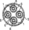
With reference to Fig. 1, this figure is the partial sectional view of heater of the present invention.It shows the oxidation reaction chamber 1 with 2 and outlets 3 of an inlet.Between entrance and exit, runner 4 is provided with in the mode of carrying out heat exchange with process chamber 8.The nozzle 6 that cartridge 5 is spaced apart for the length in longshore current road 4 provides the pipeline that transmits fuel.The nozzle setting that is spaced, so fuel sends into oxidation reaction chamber with certain speed, the fuel stream through each nozzle can not produce flame because of fuel flows to mix with the oxidation of flowing through the oxidizing chamber passage like this.Will be with more uniform mode and the oxidant reaction that passes through the oxidizing chamber space with bright flame burnt fuel.There is shown four groups of nozzles, but the nozzle of any amount can be set according to the required heat flow in process chamber.The volume of oxidizing chamber preferably makes it that enough Mixed Delay time is arranged between each nozzle, so that made the oxidized of the overwhelming majority through nozzle before more fuel enters.
Heat exchange is carried out with oxidation reaction chamber 1 in process chamber 8.Process stream enters the process chamber by import 11 and flows out from exporting 12.There is shown an oil-to-water heat exchanger 10, it is used to cool off the process stream that flows out from the process chamber.Fluid by the oil-to-water heat exchanger heating enters from water-cooled inlet 14, discharges by water-cooled outlet 13.The fluid that is heated by the water-cooled heater can be process fluid, the boiler feedwater as the insertion that is heated and/or evaporates.In some processes, for example form the pyrolysis process of the hydrocarbon of rare hydrocarbon, wish that cooling rapidly is to reduce the formation of byproduct.
The coke inhibitor can join in the fuel by as directed inhibition pipeline 9 such inhibitor spraying systems.This inhibitor injection line comprises a control valve and a control system of controlling inhibitor and fuel stream ratio.
Cartridge comprises a plurality of nozzles 6 of arranging along the length of oxidation reaction chamber (shown in the figure four).Nozzle is communicated with oxidation reaction chamber and cartridge.A plurality of nozzles are used for evenly discharging heat at oxidation reaction chamber.The size of nozzle makes the Temperature Distribution in the process chamber suitable.General hope obtains almost even temperature distribution, because it can reduce the maximum temperature of given heat flow.Because the material of constructing device has determined maximum temperature, for identical construction material, even temperature distributes will increase the possibility that discharges heat.The quantity of nozzle only is subjected to the size restrictions of employed nozzle.If use more nozzle, in general the necessary size of nozzle is less.Less nozzle is compared with the easier installation of bigger nozzle.The quantity of nozzle can and be installed between the possibility and select at Temperature Distribution mean value.
There are following current in shown process chamber and oxidizing chamber, but can be adverse current, and perhaps the mode with a kind of both combinations flows, and for example oxidizing chamber is a kind of U-shaped tubular construction.This structure may be more satisfactory to handling the different phenomenon of thermal expansion of pipeline.
According to specific process, can supply with catalyst to the process chamber.
Shown preheater 7 heated oxidants stream is heated to certain temperature with the temperature of this oxidant, is enough to oxidant stream and mixture heating from the fuel of first nozzle are produced the nonflame oxidation under this temperature.For example, this preheater can be a burner, in this burner, fuel mixes with some oxidants and burns and improves the temperature of oxidant, and perhaps oxidant can be by both carry out heat exchange and are preheated with one of effluent of process chamber or oxidizing chamber or they.The mode that can also utilize heat exchange to combine with burner.
As a kind of selection,, and oxidant pushed the fuel stream that is rich in fuel surpassing under the temperature of said mixture by in an oxidant pipe rather than in cartridge, provide nozzle that oxidant can be entered in the fuel in classification.
With reference to Fig. 2, this figure is the cutaway view of another embodiment.In this embodiment, process chamber 8 is some pipes, and these pipes are held together the shell 104 that is positioned at insulation.This insulation shell needs not be pressure vessel, but will reduce the heat loss of the pipe that comprises reative cell.Cartridge 5 is positioned at the inside of oxidation reaction chamber 1, and nozzle 6 is communicated with these two chambers.
With reference to Fig. 3, the figure shows another alternate embodiment.In this embodiment, process chamber 8 is pipes that are arranged in insulation shell 401 that some are held together.This insulation shell also limits a combustion chamber.Cartridge 5 is in the insulation shell between the pipe that is limiting the process chamber.Shown in limit the process chamber pipe and cartridge more closely be bundled together, but since be necessary required pressure fall and shell dimension between select, also can be spaced between these pipes.This selectable method can and have the heat exchanger tube of the dividing plate that separates pipe near the appearance of shell, and guiding burning gases stream passes the pipe of qualification process chamber back and forth.
Also can provide oxidation catalyst to oxidizing chamber.This oxidation catalyst can be placed in the substrate as aluminium, perhaps does coating on tube wall.Oxidation catalyst is useful to enlarging the effective temperature scope of stably carrying out the nonflame oxidation.Oxidation catalyst to oxidizing chamber reach with take place before the temperature of non-catalytic oxidation reaction the startup stage also be useful.In addition, catalyst can reduce the required volume of oxidizing chamber effectively.
Unless in fuel stream, comprise the inhibitor that forms carbon, in order to obtain flameless combustion, can in cartridge, produce a lot of carbon to the preheating of hydrocarbon.The inhibitor that suppresses carbon formation can be carbon dioxide, steam, hydrogen or their mixture.Because it is higher to produce the cost of hydrogen, carbon dioxide and steam are best.
According to following reaction equation, under the temperature that has raise, from methane, form carbon:
This reaction is a kind of reversible reaction, and works to suppress carbon formation by back reaction hydrogen.
Suppress the formation of carbon by following reaction carbon dioxide:
Suppress the formation of carbon by following reaction vapor:
React according to converted gas:
Carbon monoxide and carbon dioxide are kept balance at elevated temperatures.
When fuel is methane basically, about 1: 1 mol ratio of steam and methane will be enough to be suppressed under about 1370 ℃ temperature and form carbon.When using steam to do to form the inhibitor of carbon, the mol ratio of methane and steam is preferably in about 1: 1 to 2: 1 scope.When using carbon dioxide to do to form the inhibitor of carbon, the mol ratio of carbon dioxide and methane is preferably in about 1: 1 to 3: 1 scope.Because methane has higher heat endurance compared with lighter hydrocarbon, fuel preferably is made up of methane basically.Because inhibitor reduces burn rate and reduces peak temperature, inhibitor is very useful.
If pre-heating fuel indistinctively before fuel being added oxidation stream, or the time of staying of the fuel of any preheating is shorter, then can not need the carbon inhibitor.
The cold start-up of heater of the present invention can be used flaming combustion.Initial igniting can realize by the material that produces spark, as an Electric spark ignitor, a spark lighter or insert an igniter temporarily.Heater preferably is raised to certain temperature rapidly, keeps flameless combustion so that the time cycle minimum of flaming combustion under this temperature.The heating rate of the thermal gradient restriction heater that common heater can allow.
Generally when the temperature of mixing the reaction that do not limit between oxidant stream and the fuel and mixed flow is higher than the auto-ignition temperature of this mixed flow, form flameless combustion.High temperature by avoiding mixing point and less fuel increment sneaked into realize this burning in the oxidant.Because have a bright interface between unburned fuel and combustion product, the existence of flame is obvious.For fear of the formation of flame, fuel and oxidant are heated to about 815-1370 ℃ before being preferably in mixing.Fuel preferably mixes with oxidant stream with small incremental, so that can more promptly mix.For example, can add enough fuel with certain increment and burn, the temperature that gas is flowed improves 20-100 ℃.
Can use the technology of heater of the present invention to generally comprise (but being not limited only to this): steam methane reforming, alkene production, production of styrene, ammonia production, to encircle the reformation of amine production, hydrocarbon oxidation catalyst agent, the control of boiling or Temperature Distribution again in the boiling again of liquid, the active distillation in the rare basic chloride manufacturing of pi-allyl or second, the still-process.
With reference to accompanying drawing 4, the process chamber is arranged in the combustion chamber pipe that limits combustion chamber 1, and the pipe that limits combustion chamber 1 is in a bigger pipe, and fuel is in big pipe and limit outside some pipes of oxidizing chamber and flow.Fuel nozzle 6 is positioned at the pipe that fuel and oxidizing chamber are separated, and fuel flows into the oxidation nozzle by nozzle.The advantage of this structure is to have only a bigger pipe to admit fuel stream.
With reference to accompanying drawing 5, the figure shows another kind of structure, rather than the pipe of the cartridge 5 of concentric pipe and the process of qualification chamber 8 is positioned at the pipe that limits oxidizing chamber 1.This structure provides a bigger cross-sectional area for burning gases expediently.It would be desirable the cost squeeze that reduces burning gases, and by this larger-diameter pipe with and interior minimum pressure reduce the cost of pipe.
With reference to accompanying drawing 6, the figure shows the another kind of structure that is similar to Fig. 5, the cartridge shown in its difference is is positioned at the outside of the pipe that limits combustion chamber 1.Nozzle 6 are cartridges 5 with the pipe that limits combustion chamber 1 between tubulose be connected.The advantage of this structure is more easily to control the temperature of fuel, and has eliminated the demand to the additive that suppresses coke formation.
With reference to accompanying drawing 7, the figure shows the structure of a kind of Fig. 5 of being similar to, this structure has additional feature, and promptly combustion chamber stream is separated, and the inlet of oxidizing chamber 2 approaches the centre of oxidizing chamber 8 length.Stream from inlet is separated to flow to separately direction.Because the length of combustion chamber runner, the oxidizing chamber of this separation allow long process chamber passage, and the air-flow in the oxidizing chamber has been reduced half.Like this, reduce pressure by about eight factors that are similar to the burning gallery size and fall.Because the importance of the compression of the financial cost of process, this structure is very useful.This variation may be desirable to having long straight runner.Change as another kind, as shown in Figure 6, cartridge can be positioned at the outside of oxidizing chamber.
With reference to accompanying drawing 8, the figure shows the embodiment of the oxidation stream that another kind separated.This kind changes in-line portion oxidant, and inlet is divided into the runner of direction separately with T shape.
With reference to accompanying drawing 9, the figure shows a kind of embodiments of the invention that utilize with oxidizing chamber of rectangular cross section.This process chamber is the pipe fitting that is arranged in casing.The oxidizing chamber of this rectangle can be made greatlyyer easily, is enough to contain many processes chamber 8.The pipe of this process chamber can be the pipe of whole parallel connections or series flow, or the pipe of parallel connection and serial connection combination.Only show one deck pipe among the figure, also can be arranged to the multilayer pipe.When air-flow flowed with the form of partly connecting at least, at one end inlet porting and outlet were desirable, have reduced the problem that the pipe thermal expansion brings thus.
Also can use the heat exchanger of another kind of structure, at this as a kind of reference, as disclosed corrugated plating heat exchanger in No. the 4029146th, the United States Patent (USP).To the corrugated plating heat exchanger, perhaps cartridge can be inserted in the oxidation fluid space of suitable fuel distribution, perhaps provide the 3rd group of fluid stream for the nozzle in the space between fuel stream and oxidant stream.
Oxidizing chamber can be vertical, level or tilt, and contains one when fixed catalytic bed at process heater, and this chamber is preferably vertical.
Process heater of the present invention can be used in the production of styrene, and this production process chamber is undertaken by the dehydrogenation of ethyl group benzene-vinyl benzene (styrene) under catalyst action, and for example a kind of iron oxide-potassium oxide promotes catalyst.For example, dehydrogenation can 550-680 ℃, approximately carry out under the pressure of 20Kpa (3Psia)-140Kpa (20Psia).Steam is added the local pressure (improving the equilibrium ratio of product thus) that the ethyl group benzene raw materials reduces hydrocarbon, and increase with the temperature that reduces to cause owing to the endothermic reaction as a thermal acceptor.Most of catalyst need the steam and the mol ratio of hydrocarbon to be approximately 7 to 10.Concerning liquid fuel, liquid space velocity hourly is generally at approximately 0.4-0.5 hour
-1(hour
-1).Because the stability of output and catalyst wishes that pressure is lower, but higher pressure has reduced the cost (cost that comprises compression device) of compressed products.This is a kind of endothermic reaction, and preferably finishes a kind of reaction of approximate isothermal.Temperature forms undesirable byproduct (comprising coke) when increasing ratio increases, and output also reduced when temperature reduced.Like this, wish under the condition of approximate isothermal, to carry out certain embodiments.The benefit of being recognized that provides more uniform temperature to bring is to reduce use, increase output and the selectivity of steam, the formation and/or the increase operating pressure of minimizing coke under than the operation of high production.Although most preferred embodiment is as a kind of heater with the present invention, there is dehydrogenation in this heater at least a portion of the process chamber of heating by flameless combustion, but the present invention can be in the application of vinyl benzene-styrene dehydrogenation or as a kind of heater, or as the heater before a kind of heater.
As a kind of steam reforming furnace, the present invention utilizes the catalytic process chamber that hydrocarbon and steam-reforming are hydrogen, carbon monoxide and carbon dioxide.This is a kind of high endothermic reaction, and this reaction has the higher temperature that helps to make from hydrogen in the hydrocarbon material and carbon monoxide balance.Concerning the reaction that produces hydrogen by steam reformation, methane is best raw material, but also can use the hydrocarbon that is not methane.Molecular wt is big more, and the trend of the coke of formation is high more.Like this, when the raw material that uses as naphtha, generally need the ratio of steam and carbon higher.Steam generally is approximately 3 to 5 with the mol ratio of carbon, and space velocity was generally very high, at 5000-8000 hour
-1(hour
-1), temperature generally is approximately 800-870 ℃, and pressure generally is approximately 2-2.5Mpa (300-350Psia).Higher temperature helps the balance of hydrogen and methane, and generally is that not exceeding under 25 the temperature in its outlet in the purity of heater outlet place hydrogen at least is to be in poised state.Catalyst is a nickel-base catalyst, and can contain potassium so that stop the formation of coke.
Can further handle by reforming for the second time by the hydrogen production that steam reformation forms, for example methyl alcohol or ammonia.
Because disperse burning to make heat distribution even, the application of the present invention in steam reformation can make the reaction chamber temperature of definite maximum have higher mean temperature.Like this, maybe can reduce the ratio of steam, maybe can strengthen the conversion of similar tube wall temperature.
When the heater that applies the present invention to make hydrocarbon heat be cracked into rare hydrocarbon product process, can use 775-950 ℃ reaction temperature and the holdup time of 0.1-0.8 second.Reaction temperature is very relevant with specific hydrocarbon material and holdup time.Light raw material, for example methane can be processed under higher temperature and higher conversion condition.Heavier feedstocks, for example gas-oil increases owing to form the trend of coke and other undesirable byproducts, needs lower temperature.Approximately the holdup time of 0.1-0.15 second is best.The inlet that the steam that dilutes is added the heater hydrocarbon stops the deposition of coke, and reduces the partial pressure of hydrocarbon.Cooling can make reative cell directly with the mode that contacts as diesel oil, perhaps carry out in the mode of carrying out heat exchange indirectly.Since can be under more useful level switching energy, preferably cool off indirectly.
The present invention can be used for as destilling tower reboiler or vacuum flashing distillation feed heater.These operations often comprise heats hydrocarbon to the limiting temperature that is tending towards forming coke, and the present invention has reduced the maximum temperature of hydrocarbon in the heater so more equably to the hydrocarbon heat transfer.Has minimizing NO in addition
XThe advantage that produces.
Claims (12)
1. process heater comprises:
An oxidation reaction chamber (1), this oxidizing chamber (1) has an oxidant inlet (2), a combustion product outlet (3), and a runner (4) that is positioned between inlet (2) and the outlet (3);
The cartridge (5) that fuel mixture can be flowed to a plurality of fuel nozzles (6) in the oxidizing chamber (1), each nozzle (6) gets up cartridge (5) and oxidizing chamber (1) internal communication, and each nozzle (6) is to be provided with along the runner (4) between inlet (2) and the outlet (3);
A preheater (7) that communicates with oxidizing chamber inlet (2), this preheater (7) can improve the temperature of oxidant, make from the fuel of locating near the fuel nozzle (6) of oxidizing chamber inlet (2) and the temperature of oxidant mixture and be higher than the auto-ignition temperature that the fuel from the fuel nozzle (6) of enter the mouth near oxidizing chamber (2) mixes with oxidant, wherein the heat transfer of oxidized portion can not make the temperature of the mixture near the oxidizing chamber (1) each nozzle (6) be lower than the auto-ignition temperature of the mixture that is mixed near the oxidizing chamber (1) of each nozzle (6), it is characterized in that heater also comprises an endothermic reaction process chamber (8) of carrying out heat exchange with oxidation reaction chamber (1).
2. process heater as claimed in claim 1, also comprise a coke inhibitor spraying system (9), this coke inhibitor spraying system communicates with fuel feed pipe (5), it is characterized in that, coke inhibitor quantity delivered can suppress the formation of coke effectively under cartridge (5) operating temperature.
3. process heater as claimed in claim 1 is characterized in that, cartridge (5) is the pipe that is located substantially on oxidation reaction chamber (1) central interior.
4. process heater as claimed in claim 3 is characterized in that, oxidation reaction chamber (1) is located substantially on process chamber (8) central interior.
5. process heater as claimed in claim 1 is characterized in that, process chamber (8) are high-temperature decomposition reaction chambers that is used for rare hydrocarbon product.
6. process heater as claimed in claim 1 is characterized in that, the process chamber is effective as a steam methane reforming reative cell.
7. process heater as claimed in claim 1 is characterized in that process heater is an ethyl group benzene dehydrogenation heater.
One kind by an oxidation reaction chamber (1) to process reaction provide heat method, oxidation reaction chamber wherein (1) has an oxidant inlet (2), a combustion product outlet (3) and a runner (4) that is positioned between inlet (2) and the outlet (3), described method comprises the steps:
A kind of fuel is provided;
Add the coke inhibitor with certain amount in fuel, under the heater operating temperature, this addition can suppress the formation of coke effectively;
Fuel mixture is flowed to a plurality of fuel nozzles (6) in the oxidizing chamber (1), and each nozzle (6) is along runner (4) setting between inlet (2) and the outlet (3);
With oxidizer preheat, make oxidant be higher than from mixing temperature near the fuel of the fuel nozzle (6) of oxidizing chamber inlet (2) oxidant with from auto-ignition temperature near the fuel mix of the fuel nozzle (6) of oxidizing chamber inlet (2), it is characterized in that this method also comprise with the form of carrying out heat exchange with oxidation reaction chamber (1) in the future the heat of automatic oxidation reaction chamber (1) send endothermic reaction process chamber (8) to, the heat transfer of oxidized portion can not make the temperature of the mixture near each fuel nozzle (6) the oxidizing chamber (1) be lower than the auto-ignition temperature of the mixture that is mixed near this each fuel nozzle (6) the oxidizing chamber (1) in oxidation reaction chamber (1).
9. method as claimed in claim 8 is characterized in that, process is a kind of steam methane reforming process.
10. method as claimed in claim 8 is characterized in that, process is a kind of high-temperature decomposition reaction process that is used for rare hydrocarbon product.
11. method as claimed in claim 8 is characterized in that, process is a kind of ethyl group benzene certain embodiments.
12. method as claimed in claim 8 is characterized in that, the component of coke inhibitor is to select from the group that comprises carbon dioxide and steam.
Applications Claiming Priority (2)
| Application Number | Priority Date | Filing Date | Title |
|---|---|---|---|
| US6243997P | 1997-10-08 | 1997-10-08 | |
| US60/062,439 | 1997-10-08 |
Publications (2)
| Publication Number | Publication Date |
|---|---|
| CN1274414A CN1274414A (en) | 2000-11-22 |
| CN1163687C true CN1163687C (en) | 2004-08-25 |
Family
ID=22042493
Family Applications (1)
| Application Number | Title | Priority Date | Filing Date |
|---|---|---|---|
| CNB988099829A Expired - Lifetime CN1163687C (en) | 1997-10-08 | 1998-10-08 | Flameless combuster process heater |
Country Status (23)
| Country | Link |
|---|---|
| US (2) | US7025940B2 (en) |
| EP (1) | EP1021682B1 (en) |
| JP (1) | JP4602546B2 (en) |
| KR (1) | KR100535730B1 (en) |
| CN (1) | CN1163687C (en) |
| AT (1) | ATE214139T1 (en) |
| AU (1) | AU734708B2 (en) |
| BR (1) | BR9812738A (en) |
| CA (1) | CA2304681C (en) |
| CZ (1) | CZ298233B6 (en) |
| DE (1) | DE69804124T2 (en) |
| DK (1) | DK1021682T3 (en) |
| EA (1) | EA003626B1 (en) |
| ES (1) | ES2174498T3 (en) |
| HU (1) | HUP0003928A3 (en) |
| ID (1) | ID24367A (en) |
| NO (1) | NO318613B1 (en) |
| NZ (1) | NZ503462A (en) |
| PL (1) | PL191124B1 (en) |
| PT (1) | PT1021682E (en) |
| TR (1) | TR200000915T2 (en) |
| UA (1) | UA50853C2 (en) |
| WO (1) | WO1999018392A1 (en) |
Cited By (1)
| Publication number | Priority date | Publication date | Assignee | Title |
|---|---|---|---|---|
| CN101918761B (en) * | 2007-07-20 | 2012-06-27 | 国际壳牌研究有限公司 | A flameless combustion heater |
Families Citing this family (92)
| Publication number | Priority date | Publication date | Assignee | Title |
|---|---|---|---|---|
| JP2004531440A (en) * | 2001-03-05 | 2004-10-14 | シエル・インターナシヨネイル・リサーチ・マーチヤツピイ・ベー・ウイ | Apparatus and method for producing hydrogen |
| US6821501B2 (en) | 2001-03-05 | 2004-11-23 | Shell Oil Company | Integrated flameless distributed combustion/steam reforming membrane reactor for hydrogen production and use thereof in zero emissions hybrid power system |
| WO2003022417A2 (en) * | 2001-06-27 | 2003-03-20 | Nu Element, Inc. | Modular micro-reactor architecture and method for fluid processing devices |
| US7244868B2 (en) | 2002-06-25 | 2007-07-17 | Shell Oil Company | Process for the dehydrogenation of an unsaturated hydrocarbon |
| FR2842892B1 (en) * | 2002-07-24 | 2005-03-18 | Centre Nat Rech Scient | INSTALLATION AND METHOD FOR THE PRODUCTION OF COLD BY A REVERSAL SORPTION SYSTEM |
| EP1534627A2 (en) * | 2002-09-05 | 2005-06-01 | Shell Internationale Researchmaatschappij B.V. | Apparatus and process for production of high purity hydrogen |
| US6783206B2 (en) | 2002-11-15 | 2004-08-31 | Hewlett-Packard Development Company, L.P. | Vacuum platen assembly for fluid-ejection device with anti-clog vacuum hole sidewall profiles |
| US20040185398A1 (en) * | 2002-12-20 | 2004-09-23 | Fina Technology, Inc. | Method for reducing the formation of nitrogen oxides in steam generation |
| NL1023570C2 (en) * | 2003-05-30 | 2004-12-01 | Nederlandse Gasunie Nv | Homogeneous oxidation. |
| ITBO20040296A1 (en) * | 2004-05-11 | 2004-08-11 | Itea Spa | High efficiency and reduced environmental impact combustors, and processes for the production of electricity deriving from it |
| US7168949B2 (en) | 2004-06-10 | 2007-01-30 | Georgia Tech Research Center | Stagnation point reverse flow combustor for a combustion system |
| US7425127B2 (en) | 2004-06-10 | 2008-09-16 | Georgia Tech Research Corporation | Stagnation point reverse flow combustor |
| US7293983B2 (en) * | 2005-03-01 | 2007-11-13 | Fina Technology, Inc. | Heating hydrocarbon process flow using flameless oxidation burners |
| PL1856443T3 (en) * | 2005-03-10 | 2016-01-29 | Shell Int Research | A multi-tube heat transfer system for the combustion of a fuel and heating of a process fluid and the use thereof |
| CN101163919B (en) * | 2005-03-10 | 2010-10-13 | 国际壳牌研究有限公司 | Method of starting up a direct heating system for the flameless combustion of fuel and direct heating of a process fluid |
| JP2008532747A (en) * | 2005-03-10 | 2008-08-21 | シエル・インターナシヨネイル・リサーチ・マーチヤツピイ・ベー・ウイ | Heat transfer system for fuel combustion and process fluid heating and method of use thereof |
| US20060246388A1 (en) * | 2005-04-29 | 2006-11-02 | Hauck Manufacturing Company | Reduced NOx method of combustion |
| JP2007091584A (en) * | 2005-09-27 | 2007-04-12 | Samsung Sdi Co Ltd | Fuel reforming apparatus |
| US8603222B2 (en) * | 2005-10-21 | 2013-12-10 | Calix Ltd. | System and method for calcination/carbonation cycle processing |
| US20080093125A1 (en) * | 2006-03-27 | 2008-04-24 | Potter Drilling, Llc | Method and System for Forming a Non-Circular Borehole |
| CN101466461B (en) | 2006-03-31 | 2012-06-20 | Calix有限公司 | System and method for the calcination of minerals |
| US8490581B2 (en) | 2006-06-15 | 2013-07-23 | Exxonmobil Research And Engineering Company | Advanced fired heater unit for use in refinery and petro-chemical applications |
| TW200846282A (en) * | 2006-11-30 | 2008-12-01 | Shell Int Research | Systems and processes for producing hydrogen and carbon dioxide |
| FR2913097B1 (en) * | 2007-02-26 | 2009-04-24 | Inst Francais Du Petrole | POROUS BURNER WITH HYDROGEN WITHOUT PREMIX |
| WO2008124062A1 (en) | 2007-04-05 | 2008-10-16 | Worcester Polytechnic Institute | Composite structures with porous anodic oxide layers and methods of fabrication |
| JP2010534313A (en) * | 2007-07-20 | 2010-11-04 | シエル・インターナシヨナル・リサーチ・マートスハツペイ・ベー・ヴエー | Flameless combustion heater |
| BRPI0814798A2 (en) * | 2007-07-20 | 2019-09-24 | Shell Int Research | flameless combustion heater |
| US8671658B2 (en) | 2007-10-23 | 2014-03-18 | Ener-Core Power, Inc. | Oxidizing fuel |
| US20090136406A1 (en) * | 2007-11-27 | 2009-05-28 | John Zink Company, L.L.C | Flameless thermal oxidation method |
| US20090133854A1 (en) * | 2007-11-27 | 2009-05-28 | Bruce Carlyle Johnson | Flameless thermal oxidation apparatus and methods |
| ITMI20072290A1 (en) * | 2007-12-06 | 2009-06-07 | Itea Spa | COMBUSTION PROCESS |
| JP2009186023A (en) * | 2008-02-01 | 2009-08-20 | Ihi Corp | Combustion heater |
| WO2009096562A1 (en) * | 2008-02-01 | 2009-08-06 | Ihi Corporation | Combustion heater |
| EP2288583A1 (en) * | 2008-04-09 | 2011-03-02 | Shell Internationale Research Maatschappij B.V. | A method of improving a dehydrogenation process |
| US8084660B2 (en) * | 2008-04-18 | 2011-12-27 | Fina Technology, Inc | Use of direct heating device with a reheater in a dehydrogenation unit |
| CA2740055A1 (en) * | 2008-10-08 | 2010-04-15 | Potter Drilling, Inc. | Methods and apparatus for thermal drilling |
| US8701413B2 (en) | 2008-12-08 | 2014-04-22 | Ener-Core Power, Inc. | Oxidizing fuel in multiple operating modes |
| US20100275611A1 (en) * | 2009-05-01 | 2010-11-04 | Edan Prabhu | Distributing Fuel Flow in a Reaction Chamber |
| US8652239B2 (en) | 2010-05-03 | 2014-02-18 | Worcester Polytechnic Institute | High permeance sulfur tolerant Pd/Cu alloy membranes |
| US8992765B2 (en) | 2011-09-23 | 2015-03-31 | Uop Llc | Process for converting a hydrocarbon feed and apparatus relating thereto |
| US9273606B2 (en) | 2011-11-04 | 2016-03-01 | Ener-Core Power, Inc. | Controls for multi-combustor turbine |
| US9279364B2 (en) | 2011-11-04 | 2016-03-08 | Ener-Core Power, Inc. | Multi-combustor turbine |
| CA3092028C (en) | 2012-01-13 | 2022-08-30 | Lummus Technology Llc | Process for separating hydrocarbon compounds |
| US9359948B2 (en) | 2012-03-09 | 2016-06-07 | Ener-Core Power, Inc. | Gradual oxidation with heat control |
| US20130236839A1 (en) * | 2012-03-09 | 2013-09-12 | Flexenergy, Inc. | Gradual oxidation with heat control |
| US9273608B2 (en) | 2012-03-09 | 2016-03-01 | Ener-Core Power, Inc. | Gradual oxidation and autoignition temperature controls |
| US9347664B2 (en) | 2012-03-09 | 2016-05-24 | Ener-Core Power, Inc. | Gradual oxidation with heat control |
| US9017618B2 (en) | 2012-03-09 | 2015-04-28 | Ener-Core Power, Inc. | Gradual oxidation with heat exchange media |
| US9381484B2 (en) | 2012-03-09 | 2016-07-05 | Ener-Core Power, Inc. | Gradual oxidation with adiabatic temperature above flameout temperature |
| US8926917B2 (en) | 2012-03-09 | 2015-01-06 | Ener-Core Power, Inc. | Gradual oxidation with adiabatic temperature above flameout temperature |
| US9267432B2 (en) | 2012-03-09 | 2016-02-23 | Ener-Core Power, Inc. | Staged gradual oxidation |
| US9206980B2 (en) | 2012-03-09 | 2015-12-08 | Ener-Core Power, Inc. | Gradual oxidation and autoignition temperature controls |
| US9534780B2 (en) | 2012-03-09 | 2017-01-03 | Ener-Core Power, Inc. | Hybrid gradual oxidation |
| US9234660B2 (en) | 2012-03-09 | 2016-01-12 | Ener-Core Power, Inc. | Gradual oxidation with heat transfer |
| US9353946B2 (en) | 2012-03-09 | 2016-05-31 | Ener-Core Power, Inc. | Gradual oxidation with heat transfer |
| US9371993B2 (en) | 2012-03-09 | 2016-06-21 | Ener-Core Power, Inc. | Gradual oxidation below flameout temperature |
| US9567903B2 (en) | 2012-03-09 | 2017-02-14 | Ener-Core Power, Inc. | Gradual oxidation with heat transfer |
| KR20140138899A (en) * | 2012-03-09 | 2014-12-04 | 에너-코어 파워, 인코포레이티드 | Gradual oxidation with heat transfer |
| US9726374B2 (en) | 2012-03-09 | 2017-08-08 | Ener-Core Power, Inc. | Gradual oxidation with flue gas |
| US9359947B2 (en) | 2012-03-09 | 2016-06-07 | Ener-Core Power, Inc. | Gradual oxidation with heat control |
| US9194584B2 (en) | 2012-03-09 | 2015-11-24 | Ener-Core Power, Inc. | Gradual oxidation with gradual oxidizer warmer |
| US8980192B2 (en) | 2012-03-09 | 2015-03-17 | Ener-Core Power, Inc. | Gradual oxidation below flameout temperature |
| US9328916B2 (en) | 2012-03-09 | 2016-05-03 | Ener-Core Power, Inc. | Gradual oxidation with heat control |
| US9328660B2 (en) | 2012-03-09 | 2016-05-03 | Ener-Core Power, Inc. | Gradual oxidation and multiple flow paths |
| US8980193B2 (en) | 2012-03-09 | 2015-03-17 | Ener-Core Power, Inc. | Gradual oxidation and multiple flow paths |
| EP2855005A2 (en) | 2012-05-24 | 2015-04-08 | Siluria Technologies, Inc. | Oxidative coupling of methane systems and methods |
| JP2013249605A (en) * | 2012-05-31 | 2013-12-12 | Ihi Corp | Gas-hydrate collecting system |
| US8801904B2 (en) | 2012-07-03 | 2014-08-12 | Aemerge, LLC | Chain drag system for treatment of carbaneous waste feedstock and method for the use thereof |
| US9670113B2 (en) | 2012-07-09 | 2017-06-06 | Siluria Technologies, Inc. | Natural gas processing and systems |
| US9598328B2 (en) | 2012-12-07 | 2017-03-21 | Siluria Technologies, Inc. | Integrated processes and systems for conversion of methane to multiple higher hydrocarbon products |
| US9476589B2 (en) * | 2013-03-13 | 2016-10-25 | Fives North American Combustion, Inc. | Diffuse combustion method and apparatus |
| RU2538754C1 (en) * | 2013-11-18 | 2015-01-10 | Государственное унитарное предприятие "Институт нефтехимпереработки Республики Башкортостан" (ГУП "ИНХП РБ") | Tube furnace with flameless combustion |
| US10047020B2 (en) | 2013-11-27 | 2018-08-14 | Siluria Technologies, Inc. | Reactors and systems for oxidative coupling of methane |
| CN110655437B (en) | 2014-01-08 | 2022-09-09 | 鲁玛斯技术有限责任公司 | System and method for ethylene to liquids |
| US10377682B2 (en) | 2014-01-09 | 2019-08-13 | Siluria Technologies, Inc. | Reactors and systems for oxidative coupling of methane |
| CA3225180A1 (en) | 2014-01-09 | 2015-07-16 | Lummus Technology Llc | Oxidative coupling of methane implementations for olefin production |
| EP2952809A1 (en) * | 2014-06-06 | 2015-12-09 | Alstom Technology Ltd | Steam generator |
| CN104132344B (en) * | 2014-08-06 | 2016-06-29 | 北京大学 | The combustion gas flameless combustion apparatus of a kind of extremely low discharged nitrous oxides and combustion method |
| EP2998018A1 (en) * | 2014-09-17 | 2016-03-23 | Linde Aktiengesellschaft | Method and system for alkane dehydrogenation |
| US9334204B1 (en) | 2015-03-17 | 2016-05-10 | Siluria Technologies, Inc. | Efficient oxidative coupling of methane processes and systems |
| US10793490B2 (en) | 2015-03-17 | 2020-10-06 | Lummus Technology Llc | Oxidative coupling of methane methods and systems |
| US20160289143A1 (en) | 2015-04-01 | 2016-10-06 | Siluria Technologies, Inc. | Advanced oxidative coupling of methane |
| US9328297B1 (en) | 2015-06-16 | 2016-05-03 | Siluria Technologies, Inc. | Ethylene-to-liquids systems and methods |
| EP3362425B1 (en) | 2015-10-16 | 2020-10-28 | Lummus Technology LLC | Separation methods and systems for oxidative coupling of methane |
| EP3442934A4 (en) | 2016-04-13 | 2019-12-11 | Siluria Technologies, Inc. | Oxidative coupling of methane for olefin production |
| FR3053767B1 (en) * | 2016-07-08 | 2019-07-05 | L'air Liquide, Societe Anonyme Pour L'etude Et L'exploitation Des Procedes Georges Claude | PROCESS FOR PREHEATING A FLUID BEFORE AN OVEN |
| EP3554672A4 (en) | 2016-12-19 | 2020-08-12 | Siluria Technologies, Inc. | Methods and systems for performing chemical separations |
| HUE064375T2 (en) | 2017-05-23 | 2024-03-28 | Lummus Technology Inc | Integration of oxidative coupling of methane processes |
| RU2020102298A (en) | 2017-07-07 | 2021-08-10 | Люммус Текнолоджи Ллс | SYSTEMS AND METHODS FOR OXIDATIVE COMBINATIONS OF METHANE |
| GB2572623B (en) | 2018-04-05 | 2020-07-29 | Intelligent Power Generation Ltd | A multi fuel flame-less combustor |
| WO2021198242A1 (en) | 2020-03-31 | 2021-10-07 | Technip France | Flameless combustion burner for an endothermic reaction process |
| WO2021244840A1 (en) * | 2020-06-02 | 2021-12-09 | Haldor Topsøe A/S | Reactor with multiple burner management system |
Family Cites Families (23)
| Publication number | Priority date | Publication date | Assignee | Title |
|---|---|---|---|---|
| USRE26990E (en) * | 1964-08-11 | 1970-11-24 | Process and apparatus for reforming hydrocarbons | |
| US4029146A (en) | 1974-04-01 | 1977-06-14 | John Zink Company | Corrugated sheet heat exchanger |
| US4104018A (en) * | 1976-11-26 | 1978-08-01 | The United States Of America As Represented By The Administrator Of The National Aeronautics And Space Administration | Combuster |
| US5181990A (en) | 1986-01-16 | 1993-01-26 | Babcock-Hitachi Kabushiki Kaisha | Pyrolysis furnace for olefin production |
| US4692306A (en) * | 1986-03-24 | 1987-09-08 | Kinetics Technology International Corporation | Catalytic reaction apparatus |
| US5059404A (en) | 1989-02-14 | 1991-10-22 | Manufacturing And Technology Conversion International, Inc. | Indirectly heated thermochemical reactor apparatus and processes |
| ZA911838B (en) * | 1990-04-03 | 1991-12-24 | Standard Oil Co Ohio | Endothermic reaction apparatus |
| US6153152A (en) * | 1990-04-03 | 2000-11-28 | The Standard Oil Company | Endothermic reaction apparatus and method |
| EP0463218B1 (en) | 1990-06-29 | 1994-11-23 | Joachim Dr.-Ing. Wünning | Method and device for combustion of fuel in a combustion chamber |
| US5427655A (en) | 1990-11-29 | 1995-06-27 | Stone & Webster Engineering Corp. | High capacity rapid quench boiler |
| US5128023A (en) | 1991-03-27 | 1992-07-07 | Betz Laboratories, Inc. | Method for inhibiting coke formation and deposiiton during pyrolytic hydrocarbon processing |
| US5536488A (en) | 1991-07-01 | 1996-07-16 | Manufacturing And Technology Conversion | Indirectly heated thermochemical reactor processes |
| US5426655A (en) | 1991-07-16 | 1995-06-20 | International Business Machines Corporation | Method and apparatus for magnetic recording of data |
| FR2683543B1 (en) | 1991-11-08 | 1994-02-11 | Inst Francais Du Petrole | PROCESS FOR THERMAL PYROLYSIS OF HYDROCARBONS USING AN ELECTRIC OVEN. |
| US5255742A (en) | 1992-06-12 | 1993-10-26 | Shell Oil Company | Heat injection process |
| JPH07503993A (en) | 1992-12-18 | 1995-04-27 | アモコ・コーポレーション | Pyrolysis method with less coking |
| US5567305A (en) | 1993-08-06 | 1996-10-22 | Jo; Hong K. | Method for retarding corrosion and coke formation and deposition during pyrolytic hydrocarbon processing |
| US5523502A (en) | 1993-11-10 | 1996-06-04 | Stone & Webster Engineering Corp. | Flexible light olefins production |
| FR2715583B1 (en) | 1994-02-02 | 1996-04-05 | Inst Francais Du Petrole | Device for carrying out chemical reactions requiring at least starting calories. |
| US5424095A (en) | 1994-03-07 | 1995-06-13 | Eniricerche S.P.A. | Ceramic vapor deposited coating using a steam-containing carrier gas and non-alkoxy silane precursors |
| US5463159A (en) | 1994-03-22 | 1995-10-31 | Phillips Petroleum Company | Thermal cracking process |
| US5559510A (en) | 1995-04-12 | 1996-09-24 | Northrop Grumman Corporation | Aircraft landing site indication and light |
| US5600051A (en) | 1995-05-19 | 1997-02-04 | Corning Incorporated | Enhancing olefin yield from cracking |
-
1998
- 1998-10-08 PL PL339763A patent/PL191124B1/en unknown
- 1998-10-08 WO PCT/EP1998/006522 patent/WO1999018392A1/en active IP Right Grant
- 1998-10-08 CA CA002304681A patent/CA2304681C/en not_active Expired - Lifetime
- 1998-10-08 JP JP2000515144A patent/JP4602546B2/en not_active Expired - Lifetime
- 1998-10-08 HU HU0003928A patent/HUP0003928A3/en unknown
- 1998-10-08 CZ CZ20001255A patent/CZ298233B6/en not_active IP Right Cessation
- 1998-10-08 UA UA2000052618A patent/UA50853C2/en unknown
- 1998-10-08 ES ES98951522T patent/ES2174498T3/en not_active Expired - Lifetime
- 1998-10-08 KR KR10-2000-7003806A patent/KR100535730B1/en not_active IP Right Cessation
- 1998-10-08 PT PT98951522T patent/PT1021682E/en unknown
- 1998-10-08 US US09/168,770 patent/US7025940B2/en not_active Expired - Lifetime
- 1998-10-08 TR TR2000/00915T patent/TR200000915T2/en unknown
- 1998-10-08 CN CNB988099829A patent/CN1163687C/en not_active Expired - Lifetime
- 1998-10-08 EP EP98951522A patent/EP1021682B1/en not_active Expired - Lifetime
- 1998-10-08 ID IDW20000645A patent/ID24367A/en unknown
- 1998-10-08 AT AT98951522T patent/ATE214139T1/en not_active IP Right Cessation
- 1998-10-08 DE DE69804124T patent/DE69804124T2/en not_active Expired - Lifetime
- 1998-10-08 NZ NZ503462A patent/NZ503462A/en unknown
- 1998-10-08 DK DK98951522T patent/DK1021682T3/en active
- 1998-10-08 AU AU97502/98A patent/AU734708B2/en not_active Ceased
- 1998-10-08 BR BR9812738-1A patent/BR9812738A/en active IP Right Grant
- 1998-10-08 EA EA200000397A patent/EA003626B1/en not_active IP Right Cessation
-
2000
- 2000-04-07 NO NO20001821A patent/NO318613B1/en unknown
-
2003
- 2003-04-01 US US10/404,845 patent/US7108730B2/en not_active Expired - Lifetime
Cited By (1)
| Publication number | Priority date | Publication date | Assignee | Title |
|---|---|---|---|---|
| CN101918761B (en) * | 2007-07-20 | 2012-06-27 | 国际壳牌研究有限公司 | A flameless combustion heater |
Also Published As
Similar Documents
| Publication | Publication Date | Title |
|---|---|---|
| CN1163687C (en) | Flameless combuster process heater | |
| CN101142016B (en) | Device and method for preparing a homogeneous mixture consisting of fuel and oxidants | |
| US7976594B2 (en) | Method and system for vaporization of liquid fuels | |
| JP3075757B2 (en) | Endothermic reactor | |
| US5476375A (en) | Staged combustion in a porous-matrix surface combustor to promote ultra-low NOx Emissions | |
| CA2601359A1 (en) | A heat transfer system for the combustion of a fuel and heating of a process fluid and a process that uses same | |
| CN1318798C (en) | Burning method of fuel reforming appts. | |
| US6685893B2 (en) | Pyrolysis heater | |
| JPS5929632B2 (en) | Hydrocarbon heating method and combustion tubular heater | |
| US3914090A (en) | Method and furnace apparatus | |
| JPH06219705A (en) | Fuel reformer | |
| CN101346176B (en) | Conversion of methane to higher hydrocarbon | |
| US3469946A (en) | Apparatus for high-temperature conversions | |
| RU2134154C1 (en) | Apparatus for performing endothermic reaction | |
| CN1051145C (en) | Endothermic reaction apparatus | |
| WO2021198242A1 (en) | Flameless combustion burner for an endothermic reaction process | |
| MXPA00003152A (en) | Flameless combustor process heater | |
| RU2148217C1 (en) | Gaseous-fuel fired boiler | |
| SA93140127B1 (en) | An endothermic reaction process |
Legal Events
| Date | Code | Title | Description |
|---|---|---|---|
| C06 | Publication | ||
| PB01 | Publication | ||
| C10 | Entry into substantive examination | ||
| SE01 | Entry into force of request for substantive examination | ||
| C14 | Grant of patent or utility model | ||
| GR01 | Patent grant | ||
| CX01 | Expiry of patent term |
Granted publication date: 20040825 |
|
| CX01 | Expiry of patent term |