CN116351534A - Raw material crushing and grinding device for building ceramic processing - Google Patents
Raw material crushing and grinding device for building ceramic processing Download PDFInfo
- Publication number
- CN116351534A CN116351534A CN202310606313.0A CN202310606313A CN116351534A CN 116351534 A CN116351534 A CN 116351534A CN 202310606313 A CN202310606313 A CN 202310606313A CN 116351534 A CN116351534 A CN 116351534A
- Authority
- CN
- China
- Prior art keywords
- plate
- raw materials
- fixedly connected
- grinding
- jar
- Prior art date
- Legal status (The legal status is an assumption and is not a legal conclusion. Google has not performed a legal analysis and makes no representation as to the accuracy of the status listed.)
- Granted
Links
Images


Classifications
-
- B—PERFORMING OPERATIONS; TRANSPORTING
- B02—CRUSHING, PULVERISING, OR DISINTEGRATING; PREPARATORY TREATMENT OF GRAIN FOR MILLING
- B02C—CRUSHING, PULVERISING, OR DISINTEGRATING IN GENERAL; MILLING GRAIN
- B02C19/00—Other disintegrating devices or methods
- B02C19/0056—Other disintegrating devices or methods specially adapted for specific materials not otherwise provided for
-
- B—PERFORMING OPERATIONS; TRANSPORTING
- B02—CRUSHING, PULVERISING, OR DISINTEGRATING; PREPARATORY TREATMENT OF GRAIN FOR MILLING
- B02C—CRUSHING, PULVERISING, OR DISINTEGRATING IN GENERAL; MILLING GRAIN
- B02C23/00—Auxiliary methods or auxiliary devices or accessories specially adapted for crushing or disintegrating not provided for in preceding groups or not specially adapted to apparatus covered by a single preceding group
- B02C23/02—Feeding devices
-
- F—MECHANICAL ENGINEERING; LIGHTING; HEATING; WEAPONS; BLASTING
- F26—DRYING
- F26B—DRYING SOLID MATERIALS OR OBJECTS BY REMOVING LIQUID THEREFROM
- F26B23/00—Heating arrangements
-
- Y—GENERAL TAGGING OF NEW TECHNOLOGICAL DEVELOPMENTS; GENERAL TAGGING OF CROSS-SECTIONAL TECHNOLOGIES SPANNING OVER SEVERAL SECTIONS OF THE IPC; TECHNICAL SUBJECTS COVERED BY FORMER USPC CROSS-REFERENCE ART COLLECTIONS [XRACs] AND DIGESTS
- Y02—TECHNOLOGIES OR APPLICATIONS FOR MITIGATION OR ADAPTATION AGAINST CLIMATE CHANGE
- Y02P—CLIMATE CHANGE MITIGATION TECHNOLOGIES IN THE PRODUCTION OR PROCESSING OF GOODS
- Y02P40/00—Technologies relating to the processing of minerals
- Y02P40/60—Production of ceramic materials or ceramic elements, e.g. substitution of clay or shale by alternative raw materials, e.g. ashes
Landscapes
- Engineering & Computer Science (AREA)
- Food Science & Technology (AREA)
- Life Sciences & Earth Sciences (AREA)
- Sustainable Development (AREA)
- Mechanical Engineering (AREA)
- General Engineering & Computer Science (AREA)
- Crushing And Grinding (AREA)
Abstract
The invention discloses a raw material crushing and grinding device for building ceramic processing, and relates to the technical field of ceramic production and processing. This kind of grinding device is smashed to raw materials for building ceramic processing, including setting up the treatment tank that is used for handling ceramic raw materials on the bottom plate, be equipped with the stoving mechanism that is used for drying ceramic raw materials on the treatment tank, stoving mechanism is including the stoving pipe that fixed connection is close to conveyer pipe one end at the treatment tank, the one end that stoving pipe is located the treatment tank inside is connected with the hot plate through a plurality of connecting plates. This kind of grinding device is smashed to raw materials for building ceramic processing, through drying mechanism's setting, carry out drying treatment to the raw materials, and through the setting of water conservancy diversion ring, prolonged the time that the raw materials stayed in the stoving intraductal, through the reheat treatment of hot plate, improved the stoving effect to ceramic raw materials, guaranteed the grinding cutter to ceramic raw materials's abrasive force, further ensured the quality and the efficiency of grinding ceramic raw materials.
Description
Technical Field
The invention relates to the technical field of ceramic production and processing, in particular to a raw material crushing and grinding device for building ceramic processing.
Background
The porcelain is made of porcelain stone, kaolin, quartz stone, mullite and the like through firing, vitreous glaze or colored drawing is applied to the surface of the porcelain, the porcelain is shaped through firing at high temperature in a kiln, the glaze color of the porcelain surface can generate various chemical changes due to different temperatures, and the raw materials of the porcelain need to be crushed and ground during the production of the porcelain, so that the porcelain can be prepared for the subsequent firing and forming work.
The raw materials used for manufacturing ceramics such as porcelain stone, kaolin, quartz stone and mullite are prevented from being improper in the transportation and storage processes, so that the surfaces of the raw materials such as porcelain stone, kaolin, quartz stone and mullite contain higher moisture, and in the process of grinding the raw materials such as porcelain stone, kaolin, quartz stone and mullite, excessive moisture easily causes the grinding cutter to adhere to the ceramic raw materials, thereby reducing the grinding force of the grinding cutter on the ceramic raw materials and further influencing the grinding quality and efficiency of the ceramic raw materials.
Disclosure of Invention
The invention aims to provide a raw material crushing and grinding device for building ceramic processing, which aims to solve the problems in the background technology.
In order to achieve the above purpose, the present invention provides the following technical solutions: the utility model provides a raw materials crushing and grinding device for building ceramic processing, includes the treatment tank that sets up on the bottom plate and is used for handling ceramic raw materials, the bottom plate is connected with the conveyer pipe that is used for carrying out ceramic raw materials to the treatment tank through first L template, the one end that the conveyer pipe kept away from the treatment tank is equipped with the collecting hopper, be equipped with the collecting box that is used for collecting the ceramic raw materials that the processing accomplished on the bottom plate, be equipped with the air exhauster on the bottom plate, be equipped with the connecting pipe on the air exhauster, the one end of connecting pipe is connected with the treatment tank, the other end and the collecting box of connecting pipe are connected, be equipped with the stoving mechanism that is used for carrying out stoving to ceramic raw materials on the treatment tank;
the drying mechanism comprises a drying pipe fixedly connected to one end of the treatment tank close to the conveying pipe, a guide ring is fixedly connected to the inside of the drying pipe, a conical guide groove is formed in one end, away from the treatment tank, of the guide ring, one end, located inside the treatment tank, of the drying pipe is connected with a heating plate through a plurality of connecting plates, and a scraping mechanism used for scraping ceramic raw materials on the inner wall of the guide ring is arranged on the first L-shaped plate.
Preferably, the treatment tank is internally provided with a crushing mechanism for crushing ceramic raw materials, the crushing mechanism comprises a crushing plate fixedly connected in the treatment tank, one side of the crushing plate, which is close to the drying pipe, is provided with a plurality of crushing rods, the crushing plate is provided with a plurality of first flow holes, and the treatment tank is provided with a pushing mechanism for pushing each crushing plate.
Preferably, the grinding mechanism used for grinding the ceramic raw material is arranged in the processing tank, the grinding mechanism comprises a grinding plate fixedly connected in the processing tank, the grinding plate is positioned below the crushing plate, one side, close to the crushing plate, of the grinding plate is provided with a plurality of grinding rods, the grinding plate is provided with a plurality of second flow holes, the diameter of each second flow hole is smaller than that of the first flow hole, and the processing tank is provided with a driving mechanism used for driving the grinding plate and the crushing plate.
Preferably, the driving mechanism comprises driving rods rotatably connected in the treatment tank, each of the driving rods is fixedly connected to the side wall of the driving rod, a U-shaped plate is fixedly connected to one side, close to the bottom plate, of the treatment tank, a motor is arranged on the U-shaped plate, and one end of each driving rod penetrates through the treatment tank and is connected with the output end of the motor.
Preferably, the pushing mechanism comprises a plurality of first fixing plates fixedly connected to the inner wall of the treatment tank, one side, close to the crushing plate, of each first fixing plate is fixedly connected with a first semicircular bulge, each crushing rod slides on each first semicircular bulge, a second fixing plate is fixedly connected to the inner wall of the driving rod, two first T-shaped rods which are symmetrically arranged are connected to each other in a sliding manner on the second fixing plate, one ends of the two first T-shaped rods are connected with the crushing rods, a first spring is sleeved on the side wall of each first T-shaped rod, and two ends of each first spring are connected with the side wall of each first T-shaped rod and the second fixing plate respectively.
Preferably, the bottom plate is provided with a shaking mechanism for shaking the treatment tank, the shaking mechanism comprises two first fixing blocks which are fixedly connected to the bottom plate and are symmetrically arranged, the two first fixing blocks are connected with second fixing blocks through telescopic components, one ends of the second fixing blocks are connected with the treatment tank, one side, close to the treatment tank, of the first fixing blocks is fixedly connected with a second L-shaped plate, the driving rod is located on the side wall of the outer portion of the treatment tank and is fixedly connected with a third fixing plate, a plurality of second semicircular protrusions are arranged on the third fixing plate, and one side of each second L-shaped plate slides on each second semicircular protrusion.
Preferably, the telescopic assembly comprises a telescopic rod fixedly connected to one side of the first fixed block, a telescopic pipe is sleeved on the side wall of the telescopic rod, one end of the telescopic pipe is connected with the second fixed block, one end of the telescopic rod, which is located inside the telescopic pipe, is fixedly connected with a telescopic plate, one side of the telescopic plate is fixedly connected with a second spring, and the other end of the second spring is connected with the bottom wall of the telescopic pipe.
Preferably, the scraping mechanism comprises a fourth fixed plate fixedly connected to the side wall of the first L-shaped plate, a second T-shaped rod is connected to the fourth fixed plate in a sliding mode, two ends of the second T-shaped rod are fixedly connected with a third L-shaped plate, one end, far away from the first L-shaped plate, of the third L-shaped plate is fixedly connected with a scraper plate matched with the inner wall of the guide ring, two ends of the third L-shaped plate are respectively connected with the fourth fixed plate and the third L-shaped plate, and a third spring is sleeved on the second T-shaped rod.
Preferably, the feeding mechanism for feeding the treatment tank in a gap is arranged on the conveying pipe, the feeding mechanism comprises a feeding box fixedly connected to the conveying pipe and close to one end of the treatment tank, a feeding plate is connected to the feeding box in a sliding mode, a discharging pipe is fixedly connected to one side, away from the conveying pipe, of the feeding box, a driving frame is fixedly connected to one end, away from the feeding box, of the feeding box, an inclined surface is formed in one side, close to the treatment tank, of the driving frame, and the third L-shaped plate slides on the inclined surface.
Preferably, the feeding box is provided with a reset component for resetting the feeding plate, the reset component comprises a fifth fixing plate fixedly connected to two opposite sides of the feeding box, two third T-shaped rods are fixedly connected to the fifth fixing plate, two sixth fixing plates are fixedly connected to two sides of the feeding plate, the third T-shaped rods are slidably connected to the sixth fixing plates, two fourth springs are sleeved on the third T-shaped rods, and two ends of each fourth spring are connected with the fifth fixing plate and the sixth fixing plate respectively.
Compared with the prior art, the invention has the beneficial effects that:
this kind of grinding device is smashed to raw materials for building ceramic processing, through drying mechanism's setting, under the stoving effect of drying tube, carry out drying treatment to the raw materials, and through the setting of water conservancy diversion ring, make the raw materials can slowly pass from the drying tube in, prolonged the time that the raw materials stayed in the drying tube, when the raw materials passes from the drying tube in, will fall to hot plate department, through the reheat treatment of hot plate, the stoving effect to ceramic raw materials has been improved, thereby avoided because of the excessive adhesion of moisture on the ceramic raw materials on the milling cutter, the milling cutter has guaranteed the milling force to ceramic raw materials, further ensured the quality and the efficiency to ceramic raw materials grinding.
This kind of grinding device is smashed with raw materials to building ceramic processing is through the setting of broken mechanism, under pushing mechanism's promotion effect, is broken before grinding the ceramic raw materials to the grinding quality to the ceramic raw materials has been improved.
Drawings
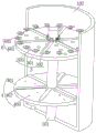
FIG. 1 is a schematic diagram of the overall structure of the present invention;
FIG. 2 is a schematic view showing the internal structure of a treatment tank according to the present invention;
FIG. 3 is a schematic view of the structure of the drying mechanism and the wiping mechanism according to the present invention;
FIG. 4 is a schematic view of the crushing mechanism and the grinding mechanism according to the present invention;
FIG. 5 is a schematic diagram of the structure of the shake mechanism and the telescopic assembly according to the present invention;
FIG. 6 is a schematic diagram of a pushing mechanism according to the present invention;
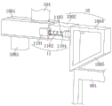
fig. 7 is a schematic view of the structure of the feeding mechanism and the reset assembly in the present invention.
In the figure: 101. a bottom plate; 102. a treatment tank; 103. a first L-shaped plate; 104. a delivery tube; 105. a collection box; 106. an exhaust fan; 107. a connecting pipe; 2. a drying mechanism; 201. a drying tube; 202. a guide ring; 203. a diversion trench; 204. a connecting plate; 205. a heating plate; 3. a crushing mechanism; 301. a breaker plate; 302. a breaker bar; 303. a first flow hole; 4. a grinding mechanism; 401. a grinding plate; 402. a grinding rod; 403. a second flow hole; 5. a driving mechanism; 501. a driving rod; 502. a motor; 503. a U-shaped plate; 6. a pushing mechanism; 601. a first fixing plate; 602. a first semicircular protrusion; 603. a second fixing plate; 604. a first T-bar; 605. a first spring; 7. a dithering mechanism; 701. a first fixed block; 702. a second fixed block; 703. a second L-shaped plate; 704. a third fixing plate; 705. a second semicircular projection; 8. a telescoping assembly; 801. a telescopic rod; 802. a telescopic tube; 803. a telescoping plate; 804. a second spring; 9. a wiping mechanism; 901. a third L-shaped plate; 902. a scraper; 903. a fourth fixing plate; 904. a second T-bar; 905. a third spring; 10. a feed mechanism; 1001. a feed box; 1002. a feed plate; 1003. a discharge pipe; 1004. a drive frame; 1005. an inclined plane; 11. a reset assembly; 1101. a fifth fixing plate; 1102. a third T-bar; 1103. a fourth spring; 1104. and a sixth fixing plate.
Detailed Description
The following description of the embodiments of the present invention will be made clearly and completely with reference to the accompanying drawings, in which it is apparent that the embodiments described are only some embodiments of the present invention, but not all embodiments. All other embodiments, which can be made by those skilled in the art based on the embodiments of the invention without making any inventive effort, are intended to be within the scope of the invention.
The invention provides a technical scheme that: the utility model provides a raw materials crushing and grinding device for building ceramic processing, including setting up the processing jar 102 that is used for handling ceramic raw materials on bottom plate 101, bottom plate 101 is connected with the conveyer pipe 104 that is used for carrying ceramic raw materials to processing jar 102 through first L template 103, the one end that conveyer pipe 104 kept away from processing jar 102 is equipped with the collecting hopper, be equipped with the collecting box 105 that is used for carrying out the collection to the ceramic raw materials that finishes handling on bottom plate 101, be equipped with air exhauster 106 on bottom plate 101, be equipped with connecting pipe 107 on the air exhauster 106, the one end of connecting pipe 107 is connected with processing jar 102, the other end of connecting pipe 107 is connected with collecting box 105, be equipped with the stoving mechanism 2 that is used for carrying out the stoving to ceramic raw materials on processing jar 102;
referring to fig. 2 and 3, the drying mechanism 2 includes a drying tube 201 fixedly connected to one end of the treatment tank 102 near the conveying tube 104, a guide ring 202 is fixedly connected in the drying tube 201, a conical guide groove 203 is provided at one end of the guide ring 202 far away from the treatment tank 102, one end of the drying tube 201 located inside the treatment tank 102 is connected with a heating plate 205 through a plurality of connecting plates 204, and a scraping mechanism 9 for scraping ceramic raw materials on the inner wall of the guide ring 202 is provided on the first L-shaped plate 103;
what needs to be explained here is: through the setting of stoving mechanism 2, under the stoving effect of stoving pipe 201, carry out drying treatment to the raw materials, and through the setting of water conservancy diversion ring 202, make the raw materials can slowly pass from stoving pipe 201 in, prolonged the time that the raw materials stayed in stoving pipe 201, when the raw materials passes from stoving pipe 201, will fall to hot plate 205 department, through the reheat treatment of hot plate 205, the stoving effect to ceramic raw materials has been improved, thereby avoided the adhesion on the grinding cutter because of the excessive moisture on the ceramic raw materials, the grinding force of grinding cutter to ceramic raw materials has been guaranteed, further ensured the quality and the efficiency to ceramic raw materials grinding.
Referring to fig. 4, a crushing mechanism 3 for crushing ceramic raw materials is disposed in a processing tank 102, the crushing mechanism 3 includes a crushing plate 301 fixedly connected in the processing tank 102, a plurality of crushing rods 302 are disposed on a side of the crushing plate 301 near a drying pipe 201, a plurality of first flow holes 303 are disposed on the crushing plate 301, and a pushing mechanism 6 for pushing each crushing plate 301 is disposed on the processing tank 102;
what needs to be explained here is: by setting the crushing mechanism 3, the ceramic raw material is crushed before being ground, so that the grinding quality of the ceramic raw material is improved.
Referring to fig. 4, a grinding mechanism 4 for grinding ceramic raw materials is disposed in a processing tank 102, the grinding mechanism 4 includes a grinding plate 401 fixedly connected in the processing tank 102, the grinding plate 401 is located below a crushing plate 301, a plurality of grinding rods 402 are disposed on one side of the grinding plate 401 near the crushing plate 301, a plurality of second flow holes 403 are disposed on the grinding plate 401, the diameter of each second flow hole 403 is smaller than that of the first flow hole 303, and a driving mechanism 5 for driving the grinding plate 401 and the crushing plate 301 is disposed on the processing tank 102;
what needs to be explained here is: by setting the grinding mechanism 4, the ceramic raw materials after drying and crushing are convenient to grind.
Referring to fig. 5, the driving mechanism 5 includes a driving rod 501 rotatably connected in the processing tank 102, each grinding rod 402 is fixedly connected to a side wall of the driving rod 501, a U-shaped plate 503 is fixedly connected to one side of the processing tank 102 near the bottom plate 101, a motor 502 is disposed on the U-shaped plate 503, and one end of the driving rod 501 penetrates through the processing tank 102 and is connected to an output end of the motor 502;
what needs to be explained here is: by the arrangement of the driving mechanism 5, the crushing rod 302 and the grinding rod 402 are facilitated to rotate.
Referring to fig. 4 and 6, the pushing mechanism 6 includes a plurality of first fixing plates 601 fixedly connected to the inner wall of the processing tank 102, a first semicircular protrusion 602 is fixedly connected to one side of each first fixing plate 601 close to the crushing plate 301, the crushing rod 302 slides on each first semicircular protrusion 602, a second fixing plate 603 is fixedly connected to the inner wall of the driving rod 501, two first T-shaped rods 604 symmetrically arranged are slidingly connected to the second fixing plate 603, one ends of the two first T-shaped rods 604 are connected to the crushing rod 302, a first spring 605 is sleeved on the side wall of the two first T-shaped rods 604, and two ends of the two first springs 605 are respectively connected to the side wall of the first T-shaped rods 604 and the second fixing plate 603;
what needs to be explained here is: through the setting of pushing mechanism 6, promote crushing rod 302 and be close to crushing board 301 motion, strike the ceramic raw materials of tiling on crushing board 301 to improve the crushing effect to ceramic raw materials.
Referring to fig. 5, a shaking mechanism 7 for shaking the processing tank 102 is disposed on the bottom plate 101, the shaking mechanism 7 includes two first fixing blocks 701 which are fixedly connected to the bottom plate 101 and are symmetrically disposed, the two first fixing blocks 701 are connected to a second fixing block 702 through a telescopic assembly 8, one ends of the two second fixing blocks 702 are connected to the processing tank 102, one side of the two first fixing blocks 701, which is close to the processing tank 102, is fixedly connected to a second L-shaped plate 703, a driving rod 501 is fixedly connected to a third fixing plate 704 on a side wall of the outer portion of the processing tank 102, a plurality of second semicircular protrusions 705 are disposed on the third fixing plate 704, and one side of the two second L-shaped plates 703 slides on each second semicircular protrusion 705;
what needs to be explained here is: by the provision of the shaking mechanism 7, the shaking of the treatment tank 102 is facilitated on the one hand, and the reciprocating pushing of the third L-shaped plate 901 is facilitated on the other hand.
Referring to fig. 5, the telescopic assembly 8 includes a telescopic rod 801 fixedly connected to one side of the first fixing block 701, a telescopic tube 802 is sleeved on a side wall of the telescopic rod 801, one end of the telescopic tube 802 is connected with the second fixing block 702, one end of the telescopic rod 801 located inside the telescopic tube 802 is fixedly connected with a telescopic plate 803, one side of the telescopic plate 803 is fixedly connected with a second spring 804, and the other end of the second spring 804 is connected with a bottom wall of the telescopic tube 802;
what needs to be explained here is: by the arrangement of the telescopic assembly 8, guiding and resetting actions are provided for the movement of the treatment tank 102.
Referring to fig. 3, the wiping mechanism 9 includes a fourth fixing plate 903 fixedly connected to a side wall of the first L-shaped plate 103, a second T-shaped rod 904 is slidably connected to the fourth fixing plate 903, one end of the two second T-shaped rods 904 is fixedly connected to a third L-shaped plate 901, one end of the third L-shaped plate 901, which is far away from the first L-shaped plate 103, is fixedly connected to a scraper 902 which is arranged in a matching manner with an inner wall of the guide ring 202, a third spring 905 is sleeved on the two second T-shaped rods 904, and two ends of the two third springs 905 are respectively connected to the fourth fixing plate 903 and the third L-shaped plate 901;
what needs to be explained here is: the ceramic raw material on the inner wall of the guide ring 202 is convenient to scrape by the arrangement of the scraping mechanism 9.
Referring to fig. 7, a feeding mechanism 10 for feeding the treatment tank 102 in a gap is arranged on a conveying pipe 104, the feeding mechanism 10 comprises a feeding box 1001 fixedly connected to one end of the conveying pipe 104 close to the treatment tank 102, a feeding plate 1002 is slidably connected to the feeding box 1001, a discharging pipe 1003 is fixedly connected to one side of the feeding box 1001 far away from the conveying pipe 104, a driving frame 1004 is fixedly connected to one end of the feeding plate 1002 far away from the feeding box 1001, an inclined plane 1005 is arranged on one side of the driving frame 1004 close to the treatment tank 102, and a third L-shaped plate 901 slides on the inclined plane 1005;
what needs to be explained here is: by setting the feeding mechanism 10, the reciprocating pushing feeding plate 1002 is contracted towards the feeding box 1001, so that reciprocating feeding of the processing tank 102 is realized, and better drying, crushing and grinding treatment of ceramic raw materials are facilitated.
Referring to fig. 7, a reset assembly 11 for resetting a feeding plate 1002 is disposed on a feeding box 1001, the reset assembly 11 includes a fifth fixing plate 1101 fixedly connected to opposite sides of the feeding box 1001, a third T-shaped rod 1102 is fixedly connected to the two fifth fixing plates 1101, a sixth fixing plate 1104 is fixedly connected to two sides of the feeding plate 1002, the two third T-shaped rods 1102 are slidably connected to the sixth fixing plate 1104, a fourth spring 1103 is sleeved on the two third T-shaped rods 1102, and two ends of the two fourth springs 1103 are respectively connected to the fifth fixing plate 1101 and the sixth fixing plate 1104;
what needs to be explained here is: the feed plate 1002 is provided with guiding and resetting actions by the arrangement of the resetting assembly 11.
Working principle: when the ceramic raw materials need to be crushed and ground, the ceramic raw materials are put into a collecting hopper, the motor 502 is started to drive the third fixed plate 704 on the driving rod 501 to rotate, the second semicircular bulge 705 is driven to synchronously rotate in the process of rotating the third fixed plate 704, when the second semicircular bulge 705 is propped against the second L-shaped plate 703 on the first fixed block 701, the processing tank 102 is pushed to move upwards under the guiding action of the interaction force and the telescopic rod 801 and the telescopic pipe 802, the drying pipe 201 is pushed to move upwards in the process of moving upwards the processing tank 102, the third L-shaped plate 901 is synchronously pushed to move upwards in the process of moving upwards the drying pipe 201, the feeding plate 1002 is pushed to shrink inwards of the feeding box 1001 under the interaction force when the third L-shaped plate 901 is propped against the inclined plane 1005 on the driving frame 1004, so that the ceramic raw materials falling into the feeding box 1001 from the conveying pipe 104 are pushed to the processing tank 102 from the discharging pipe 1003 along with the continuous rotation of the driving rod 501, the reciprocating feeding box 1001 is pushed to the feeding box 102 through the transmission of the driving plate, and the reciprocating grinding and grinding of the ceramic raw materials is more convenient to realize the processing tank 102 in the reciprocating and drying and grinding process;
when the ceramic raw material falls from the discharging pipe 1003, the ceramic raw material falls into the drying pipe 201 firstly, the raw material is dried under the drying action of the drying pipe 201, and the raw material can slowly pass through the drying pipe 201 through the arrangement of the guide ring 202, so that the stay time of the raw material in the drying pipe 201 is prolonged, when the raw material passes through the drying pipe 201, the raw material falls to the heating plate 205, and the drying effect of the ceramic raw material is improved through the reheating treatment of the heating plate 205, so that the raw material is prevented from being adhered to a grinding cutter due to excessive water on the ceramic raw material, the grinding force of the grinding cutter on the ceramic raw material is ensured, and the grinding quality and efficiency of the ceramic raw material are further ensured;
the dried raw materials flow onto the crushing plate 301 from a gap between the drying pipe 201 and the heating plate 205 under the action of centrifugal force when the drying pipe 201 rotates, after the ceramic raw materials fall onto the crushing plate 301, the raw materials are crushed under the crushing action of the crushing rod 302, and in the rotating process of the crushing rod 302, when the crushing rod 302 is propped against the first semicircular bulge 602, the crushing rod 302 is pushed to move close to the crushing plate 301 under the interaction force, and the ceramic raw materials paved on the crushing plate 301 are impacted, so that the crushing effect on the ceramic raw materials is improved;
in the process of crushing the raw materials by the crushing rod 302, the raw materials smaller than the diameter of the first flow hole 303 fall to the grinding plate 401 from the first flow hole 303 under the shaking action of the processing tank 102 and the impact action of the crushing rod 302, then the ceramic raw materials are ground under the grinding action of the grinding rod 402, the ceramic raw materials meeting the standard flow into the connecting pipe 107 from the second flow hole 403, and finally the ceramic raw materials are sent into the collecting tank 105 under the action of the exhaust fan 106, so that the crushing and grinding of the ceramic raw materials are realized.
Claims (10)
1. The utility model provides a grinding device is smashed to raw materials for building ceramic processing, is including setting up on bottom plate (101) be used for carrying out treatment jar (102) of handling ceramic raw materials, bottom plate (101) are connected with conveyer pipe (104) that are used for carrying out ceramic raw materials to treatment jar (102) through first L template (103), the one end that treatment jar (102) was kept away from to conveyer pipe (104) is equipped with the collecting hopper, be equipped with on bottom plate (101) and be used for carrying out collecting box (105) of collecting to the ceramic raw materials that the processing accomplished, be equipped with air exhauster (106) on bottom plate (101), be equipped with connecting pipe (107) on air exhauster (106), the one end of connecting pipe (107) is connected with treatment jar (102), the other end of connecting pipe (107) is connected with collecting box (105), its characterized in that: be equipped with on handling jar (102) and be used for carrying out stoving mechanism (2) to ceramic raw materials, stoving mechanism (2) are including fixed connection in handling jar (102) stoving pipe (201) that are close to conveyer pipe (104) one end, fixedly connected with water conservancy diversion ring (202) in stoving pipe (201), water conservancy diversion groove (203) that the toper set up have been seted up to the one end that handling jar (102) was kept away from to water conservancy diversion ring (202), stoving pipe (201) are located the inside one end of handling jar (102) and are connected with hot plate (205) through a plurality of connecting plates (204), be equipped with on first L template (103) and be used for scraping mechanism (9) that scrape the ceramic raw materials on the inner wall of water conservancy diversion ring (202).
2. The raw material pulverizing and grinding device for processing building ceramics according to claim 1, wherein: be equipped with in the processing jar (102) and be used for carrying out broken mechanism (3) to ceramic raw materials, broken mechanism (3) are including fixed connection broken board (301) in processing jar (102), one side that broken board (301) is close to drying tube (201) is equipped with a plurality of broken poles (302), a plurality of first circulation holes (303) have been seted up on broken board (301), be equipped with on processing jar (102) and be used for carrying out pushing mechanism (6) that promote each broken board (301).
3. The raw material pulverizing and grinding device for processing building ceramics according to claim 2, wherein: be equipped with in the processing jar (102) and be used for carrying out grinding mechanism (4) to ceramic raw materials, grinding mechanism (4) are including fixed connection grinding board (401) in processing jar (102), grinding board (401) are located the below of breaker plate (301), one side that is close to breaker plate (301) of grinding board (401) is equipped with a plurality of grinding poles (402), a plurality of second circulation holes (403) have been seted up on grinding board (401), each the diameter of second circulation hole (403) is less than the diameter of first circulation hole (303), be equipped with on processing jar (102) and be used for carrying out actuating mechanism (5) of drive to grinding board (401) and breaker plate (301).
4. A raw material crushing and grinding device for processing building ceramics according to claim 3, wherein: the driving mechanism (5) comprises driving rods (501) which are rotatably connected in the treatment tank (102), the grinding rods (402) are fixedly connected to the side walls of the driving rods (501), one side, close to the bottom plate (101), of the treatment tank (102) is fixedly connected with a U-shaped plate (503), a motor (502) is arranged on the U-shaped plate (503), and one end of each driving rod (501) penetrates through the treatment tank (102) and is connected with the output end of the motor (502).
5. The raw material pulverizing and grinding device for processing building ceramics according to claim 4, wherein: the pushing mechanism (6) comprises a plurality of first fixing plates (601) fixedly connected to the inner wall of the treatment tank (102), one side, close to the crushing plate (301), of each first fixing plate (601) is fixedly connected with a first semicircular bulge (602), each crushing rod (302) slides on each first semicircular bulge (602), a second fixing plate (603) is fixedly connected to the inner wall of the driving rod (501), two first T-shaped rods (604) which are symmetrically arranged are connected to each other in a sliding manner on the second fixing plate (603), one ends of the two first T-shaped rods (604) are connected with the crushing rods (302), first springs (605) are sleeved on the side walls of the two first T-shaped rods (604), and two ends of each first spring (605) are connected with the side walls of the corresponding first T-shaped rods (604) and the corresponding second fixing plates (603) respectively.
6. The raw material pulverizing and grinding device for processing building ceramics according to claim 5, wherein: be equipped with on bottom plate (101) and be used for carrying out shake mechanism (7) to handling jar (102), shake mechanism (7) including two first fixed blocks (701) that mutual symmetry set up of fixed connection on bottom plate (101), two first fixed block (701) are connected with second fixed block (702) through telescopic subassembly (8), two the one end of second fixed block (702) is connected with handling jar (102), two one side fixedly connected with second L template (703) that first fixed block (701) is close to handling jar (102), actuating lever (501) are located on the outside lateral wall of handling jar (102) fixedly connected with third fixed plate (704), be equipped with a plurality of second semicircle archs (705) on third fixed plate (704), two one side of second L template (703) slides on each second semicircle arch (705).
7. The raw material pulverizing and grinding device for processing building ceramics according to claim 6, wherein: the telescopic assembly (8) comprises a telescopic rod (801) fixedly connected to one side of a first fixed block (701), a telescopic pipe (802) is sleeved on the side wall of the telescopic rod (801), one end of the telescopic pipe (802) is connected with a second fixed block (702), one end of the telescopic rod (801) located inside the telescopic pipe (802) is fixedly connected with a telescopic plate (803), one side of the telescopic plate (803) is fixedly connected with a second spring (804), and the other end of the second spring (804) is connected with the bottom wall of the telescopic pipe (802).
8. The raw material pulverizing and grinding device for processing building ceramics according to claim 1, wherein: the scraping mechanism (9) comprises a fourth fixing plate (903) fixedly connected to the side wall of the first L-shaped plate (103), a second T-shaped rod (904) is connected to the fourth fixing plate (903) in a sliding mode, two ends of the second T-shaped rod (904) are fixedly connected with a third L-shaped plate (901), one end, far away from the first L-shaped plate (103), of the third L-shaped plate (901) is fixedly connected with a scraping plate (902) which is arranged in a matched mode with the inner wall of the guide ring (202), two ends of the second T-shaped rod (904) are sleeved with third springs (905), and two ends of the third springs (905) are connected with the fourth fixing plate (903) and the third L-shaped plate (901) respectively.
9. The raw material pulverizing and grinding device for processing building ceramics according to claim 8, wherein: be equipped with on conveyer pipe (104) and be used for carrying out feed mechanism (10) of clearance feeding to handling jar (102), feed mechanism (10) are including fixed connection at conveyer pipe (104) are close to feed box (1001) of handling jar (102) one end, sliding connection has feed plate (1002) on feed box (1001), one side fixedly connected with discharging pipe (1003) of conveyer pipe (104) are kept away from to feed box (1001), one end fixedly connected with drive frame (1004) of feed plate (1002) is kept away from to feed plate (1002), inclined plane (1005) have been seted up to one side that drive frame (1004) are close to handling jar (102), third L template (901) slide on inclined plane (1005).
10. The raw material pulverizing and grinding device for processing building ceramics according to claim 9, wherein: be equipped with on feeding box (1001) and be used for carrying out reset subassembly (11) to feeding plate (1002), reset subassembly (11) are including fifth fixed plate (1101) of fixed connection on the both sides that feeding box (1001) are relative, two fixedly connected with third T type pole (1102) on fifth fixed plate (1101), the both sides fixedly connected with sixth fixed plate (1104) of feeding plate (1002), two third T type pole (1102) sliding connection is on sixth fixed plate (1104), two cover is equipped with fourth spring (1103) on third T type pole (1102), two the both ends of fourth spring (1103) are connected with fifth fixed plate (1101) and sixth fixed plate (1104) respectively.
Priority Applications (1)
| Application Number | Priority Date | Filing Date | Title |
|---|---|---|---|
| CN202310606313.0A CN116351534B (en) | 2023-05-26 | 2023-05-26 | Raw material crushing and grinding device for building ceramic processing |
Applications Claiming Priority (1)
| Application Number | Priority Date | Filing Date | Title |
|---|---|---|---|
| CN202310606313.0A CN116351534B (en) | 2023-05-26 | 2023-05-26 | Raw material crushing and grinding device for building ceramic processing |
Publications (2)
| Publication Number | Publication Date |
|---|---|
| CN116351534A true CN116351534A (en) | 2023-06-30 |
| CN116351534B CN116351534B (en) | 2023-08-01 |
Family
ID=86910660
Family Applications (1)
| Application Number | Title | Priority Date | Filing Date |
|---|---|---|---|
| CN202310606313.0A Active CN116351534B (en) | 2023-05-26 | 2023-05-26 | Raw material crushing and grinding device for building ceramic processing |
Country Status (1)
| Country | Link |
|---|---|
| CN (1) | CN116351534B (en) |
Cited By (2)
| Publication number | Priority date | Publication date | Assignee | Title |
|---|---|---|---|---|
| CN117225552A (en) * | 2023-11-09 | 2023-12-15 | 佳木斯冬梅大豆食品有限公司 | Multistage crushing apparatus is used in bean flour production |
| CN117282346A (en) * | 2023-08-14 | 2023-12-26 | 江苏天味食品科技有限公司 | Efficient granular seasoning manufacturing equipment |
Citations (9)
| Publication number | Priority date | Publication date | Assignee | Title |
|---|---|---|---|---|
| CN207439065U (en) * | 2018-01-29 | 2018-06-01 | 河南鑫合实业发展有限公司 | Can dust-proof dust-removing foodstuff drying device |
| CN208911881U (en) * | 2018-03-23 | 2019-05-31 | 天津市康瑞药业有限公司 | A kind of medicament-making device preparation agitating device |
| CN110756271A (en) * | 2019-10-30 | 2020-02-07 | 福州康来生物科技有限公司 | Peach gum production is with dry integration equipment of smashing with even drying function |
| CN212538641U (en) * | 2020-05-08 | 2021-02-12 | 湖北汇金环保装备有限公司 | Coal slime drying-machine for coal mine |
| CN112403639A (en) * | 2020-10-30 | 2021-02-26 | 方森杰 | High-tech materials processing is with ceramic raw and other materials reducing mechanism |
| CN213854914U (en) * | 2020-09-28 | 2021-08-03 | 重庆升升药业有限公司 | Integrative equipment of grinding is smashed to traditional chinese medicine |
| CN216224699U (en) * | 2021-09-24 | 2022-04-08 | 河南三明食品有限公司 | Grinder is used in mushroom sauce production and processing |
| CN115194086A (en) * | 2022-06-29 | 2022-10-18 | 彭铱锋 | Casting sand processing system |
| CN115518598A (en) * | 2022-09-21 | 2022-12-27 | 高化学(江苏)化工新材料有限责任公司 | Preparation device for synthesizing dimethyl carbonate catalyst |
-
2023
- 2023-05-26 CN CN202310606313.0A patent/CN116351534B/en active Active
Patent Citations (9)
| Publication number | Priority date | Publication date | Assignee | Title |
|---|---|---|---|---|
| CN207439065U (en) * | 2018-01-29 | 2018-06-01 | 河南鑫合实业发展有限公司 | Can dust-proof dust-removing foodstuff drying device |
| CN208911881U (en) * | 2018-03-23 | 2019-05-31 | 天津市康瑞药业有限公司 | A kind of medicament-making device preparation agitating device |
| CN110756271A (en) * | 2019-10-30 | 2020-02-07 | 福州康来生物科技有限公司 | Peach gum production is with dry integration equipment of smashing with even drying function |
| CN212538641U (en) * | 2020-05-08 | 2021-02-12 | 湖北汇金环保装备有限公司 | Coal slime drying-machine for coal mine |
| CN213854914U (en) * | 2020-09-28 | 2021-08-03 | 重庆升升药业有限公司 | Integrative equipment of grinding is smashed to traditional chinese medicine |
| CN112403639A (en) * | 2020-10-30 | 2021-02-26 | 方森杰 | High-tech materials processing is with ceramic raw and other materials reducing mechanism |
| CN216224699U (en) * | 2021-09-24 | 2022-04-08 | 河南三明食品有限公司 | Grinder is used in mushroom sauce production and processing |
| CN115194086A (en) * | 2022-06-29 | 2022-10-18 | 彭铱锋 | Casting sand processing system |
| CN115518598A (en) * | 2022-09-21 | 2022-12-27 | 高化学(江苏)化工新材料有限责任公司 | Preparation device for synthesizing dimethyl carbonate catalyst |
Cited By (4)
| Publication number | Priority date | Publication date | Assignee | Title |
|---|---|---|---|---|
| CN117282346A (en) * | 2023-08-14 | 2023-12-26 | 江苏天味食品科技有限公司 | Efficient granular seasoning manufacturing equipment |
| CN117282346B (en) * | 2023-08-14 | 2024-03-29 | 江苏天味食品科技有限公司 | Efficient granular seasoning manufacturing equipment |
| CN117225552A (en) * | 2023-11-09 | 2023-12-15 | 佳木斯冬梅大豆食品有限公司 | Multistage crushing apparatus is used in bean flour production |
| CN117225552B (en) * | 2023-11-09 | 2024-01-26 | 佳木斯冬梅大豆食品有限公司 | Multistage crushing apparatus is used in bean flour production |
Also Published As
| Publication number | Publication date |
|---|---|
| CN116351534B (en) | 2023-08-01 |
Similar Documents
| Publication | Publication Date | Title |
|---|---|---|
| CN116351534B (en) | Raw material crushing and grinding device for building ceramic processing | |
| CN107824258A (en) | A kind of blue and white porcelain is fired and uses kaolin fine gtinding screening plant | |
| CN112917664B (en) | Ceramic tile processing equipment | |
| CN111364320A (en) | High-quality asphalt mixture coarse aggregate regeneration device and method based on microwave technology | |
| CN105291259A (en) | Equipment for preparing light corrosion-resistance ceramic tiles | |
| CN207478676U (en) | A kind of sandstone crush conveying device | |
| CN208606546U (en) | A kind of ceramic tile raw material spray-drying installation | |
| CN105906206A (en) | A glass bottle with good crack resistance and a preparing process thereof | |
| CN212052193U (en) | High-quality asphalt mixture coarse aggregate regenerating unit based on microwave technology | |
| CN209438682U (en) | A kind of useless brick recycling and processing device of ceramic tile production | |
| CN112138789A (en) | Ball-milling device is used in ceramic tile production | |
| CN117380335A (en) | Energy-saving and environment-friendly construction device and construction method for green building | |
| CN207874557U (en) | A kind of mortar mixing apparatus for building being convenient to clean | |
| CN104924453A (en) | Movable agitator | |
| CN115007279A (en) | Ball mill for ceramic bathroom manufacturing | |
| CN212673834U (en) | Paint slag calcining device convenient to clean | |
| CN214210757U (en) | Ball mill is used in preparation of mop pond | |
| CN210773423U (en) | Novel rapid cooling device after ceramic firing | |
| CN210409989U (en) | Special dust collecting equipment of ceramic manufacture | |
| CN208626850U (en) | A kind of filter device of electrolytic manganese residues calcining dust | |
| CN208087499U (en) | Production of Ceramics system and Production of Ceramics assembly line | |
| CN212288053U (en) | Tape casting equipment | |
| CN210718664U (en) | Kiln ash discharging device for low-alkali cement production | |
| CN105254329B (en) | A kind of preparation method of Light anticorrosive ceramic tile | |
| CN220177012U (en) | Uniform feeding structure and solid waste crushing device |
Legal Events
| Date | Code | Title | Description |
|---|---|---|---|
| PB01 | Publication | ||
| PB01 | Publication | ||
| SE01 | Entry into force of request for substantive examination | ||
| SE01 | Entry into force of request for substantive examination | ||
| GR01 | Patent grant | ||
| GR01 | Patent grant |