CN116332306A - Intelligent control device for adding coal slime water flocculant - Google Patents
Intelligent control device for adding coal slime water flocculant Download PDFInfo
- Publication number
- CN116332306A CN116332306A CN202310360865.8A CN202310360865A CN116332306A CN 116332306 A CN116332306 A CN 116332306A CN 202310360865 A CN202310360865 A CN 202310360865A CN 116332306 A CN116332306 A CN 116332306A
- Authority
- CN
- China
- Prior art keywords
- shaped
- intelligent control
- flocculant
- control device
- medicine
- Prior art date
- Legal status (The legal status is an assumption and is not a legal conclusion. Google has not performed a legal analysis and makes no representation as to the accuracy of the status listed.)
- Pending
Links
- XLYOFNOQVPJJNP-UHFFFAOYSA-N water Substances O XLYOFNOQVPJJNP-UHFFFAOYSA-N 0.000 title claims abstract description 110
- 239000003245 coal Substances 0.000 title abstract description 31
- 239000003814 drug Substances 0.000 claims abstract description 95
- 238000009826 distribution Methods 0.000 claims description 43
- 238000007667 floating Methods 0.000 claims description 17
- 230000000149 penetrating effect Effects 0.000 claims description 12
- 239000007921 spray Substances 0.000 claims description 10
- 238000007599 discharging Methods 0.000 claims description 8
- 229940079593 drug Drugs 0.000 claims description 7
- 238000009513 drug distribution Methods 0.000 claims 1
- 238000005406 washing Methods 0.000 abstract 1
- 239000008394 flocculating agent Substances 0.000 description 14
- 230000000903 blocking effect Effects 0.000 description 10
- 238000001914 filtration Methods 0.000 description 6
- 238000004062 sedimentation Methods 0.000 description 6
- 230000008859 change Effects 0.000 description 5
- 238000004140 cleaning Methods 0.000 description 4
- 238000010586 diagram Methods 0.000 description 4
- 239000002699 waste material Substances 0.000 description 4
- 230000000694 effects Effects 0.000 description 3
- 239000004744 fabric Substances 0.000 description 3
- 238000005086 pumping Methods 0.000 description 3
- 230000003247 decreasing effect Effects 0.000 description 2
- 238000012377 drug delivery Methods 0.000 description 2
- 230000005484 gravity Effects 0.000 description 2
- 230000007774 longterm Effects 0.000 description 2
- 230000007246 mechanism Effects 0.000 description 2
- 238000002360 preparation method Methods 0.000 description 2
- 239000002344 surface layer Substances 0.000 description 2
- 238000003466 welding Methods 0.000 description 2
- 206010044565 Tremor Diseases 0.000 description 1
- 230000006978 adaptation Effects 0.000 description 1
- 230000001680 brushing effect Effects 0.000 description 1
- 238000010276 construction Methods 0.000 description 1
- 230000007613 environmental effect Effects 0.000 description 1
- 238000009434 installation Methods 0.000 description 1
- 239000010410 layer Substances 0.000 description 1
- 238000004519 manufacturing process Methods 0.000 description 1
- 238000000034 method Methods 0.000 description 1
- 230000008569 process Effects 0.000 description 1
- 230000009467 reduction Effects 0.000 description 1
- 238000005507 spraying Methods 0.000 description 1
Images


Classifications
-
- C—CHEMISTRY; METALLURGY
- C02—TREATMENT OF WATER, WASTE WATER, SEWAGE, OR SLUDGE
- C02F—TREATMENT OF WATER, WASTE WATER, SEWAGE, OR SLUDGE
- C02F1/00—Treatment of water, waste water, or sewage
- C02F1/52—Treatment of water, waste water, or sewage by flocculation or precipitation of suspended impurities
- C02F1/5281—Installations for water purification using chemical agents
-
- B—PERFORMING OPERATIONS; TRANSPORTING
- B01—PHYSICAL OR CHEMICAL PROCESSES OR APPARATUS IN GENERAL
- B01F—MIXING, e.g. DISSOLVING, EMULSIFYING OR DISPERSING
- B01F25/00—Flow mixers; Mixers for falling materials, e.g. solid particles
- B01F25/70—Spray-mixers, e.g. for mixing intersecting sheets of material
- B01F25/72—Spray-mixers, e.g. for mixing intersecting sheets of material with nozzles
-
- B—PERFORMING OPERATIONS; TRANSPORTING
- B01—PHYSICAL OR CHEMICAL PROCESSES OR APPARATUS IN GENERAL
- B01F—MIXING, e.g. DISSOLVING, EMULSIFYING OR DISPERSING
- B01F35/00—Accessories for mixers; Auxiliary operations or auxiliary devices; Parts or details of general application
- B01F35/71—Feed mechanisms
- B01F35/712—Feed mechanisms for feeding fluids
-
- C—CHEMISTRY; METALLURGY
- C02—TREATMENT OF WATER, WASTE WATER, SEWAGE, OR SLUDGE
- C02F—TREATMENT OF WATER, WASTE WATER, SEWAGE, OR SLUDGE
- C02F11/00—Treatment of sludge; Devices therefor
- C02F11/12—Treatment of sludge; Devices therefor by de-watering, drying or thickening
- C02F11/14—Treatment of sludge; Devices therefor by de-watering, drying or thickening with addition of chemical agents
-
- B—PERFORMING OPERATIONS; TRANSPORTING
- B01—PHYSICAL OR CHEMICAL PROCESSES OR APPARATUS IN GENERAL
- B01F—MIXING, e.g. DISSOLVING, EMULSIFYING OR DISPERSING
- B01F2101/00—Mixing characterised by the nature of the mixed materials or by the application field
- B01F2101/305—Treatment of water, waste water or sewage
-
- C—CHEMISTRY; METALLURGY
- C02—TREATMENT OF WATER, WASTE WATER, SEWAGE, OR SLUDGE
- C02F—TREATMENT OF WATER, WASTE WATER, SEWAGE, OR SLUDGE
- C02F2201/00—Apparatus for treatment of water, waste water or sewage
- C02F2201/002—Construction details of the apparatus
-
- Y—GENERAL TAGGING OF NEW TECHNOLOGICAL DEVELOPMENTS; GENERAL TAGGING OF CROSS-SECTIONAL TECHNOLOGIES SPANNING OVER SEVERAL SECTIONS OF THE IPC; TECHNICAL SUBJECTS COVERED BY FORMER USPC CROSS-REFERENCE ART COLLECTIONS [XRACs] AND DIGESTS
- Y02—TECHNOLOGIES OR APPLICATIONS FOR MITIGATION OR ADAPTATION AGAINST CLIMATE CHANGE
- Y02W—CLIMATE CHANGE MITIGATION TECHNOLOGIES RELATED TO WASTEWATER TREATMENT OR WASTE MANAGEMENT
- Y02W10/00—Technologies for wastewater treatment
- Y02W10/10—Biological treatment of water, waste water, or sewage
Landscapes
- Chemical & Material Sciences (AREA)
- Chemical Kinetics & Catalysis (AREA)
- General Chemical & Material Sciences (AREA)
- Life Sciences & Earth Sciences (AREA)
- Hydrology & Water Resources (AREA)
- Engineering & Computer Science (AREA)
- Environmental & Geological Engineering (AREA)
- Water Supply & Treatment (AREA)
- Organic Chemistry (AREA)
- Separation Of Suspended Particles By Flocculating Agents (AREA)
Abstract
The invention provides an intelligent control device for adding a slime water flocculant, which relates to the field of intelligent control devices for feeding, and comprises the following components: two U-shaped mounting frames are symmetrically welded at the front end and the rear end of the U-shaped drainage channel, six connecting mounting holes are formed in the two U-shaped mounting frames, and the U-shaped drainage channel is connected with a drainage channel pipe of coal washing mud water through the two U-shaped mounting frames; the invention relates to a device for adding flocculant by quantitative suction, which is characterized in that two mounting brackets are symmetrically supported at the top ends of the left and right side walls of the rear half section of a U-shaped drainage channel through screw locking, each mounting bracket consists of an upper longitudinal supporting mounting plate, a lower longitudinal supporting mounting plate and two longitudinal supporting plates which are symmetrically welded between the two longitudinal supporting mounting plates, and a flocculant medicine box is fixedly arranged at the top ends of the two mounting brackets through screw locking.
Description
Technical Field
The invention relates to the technical field of intelligent control devices for feeding, in particular to an intelligent control device for adding a slime water flocculant.
Background
In the process of treating slime water in coal preparation plants, the application of flocculant is wider along with the increasing of environmental protection requirements. The preparation effect of the flocculant solution is an important link related to the concentration production process, once the flocculant is unreasonable to be prepared, the purpose of protecting the environment cannot be achieved, the waste of the flocculant can be caused, the economic burden is increased, and further, special flocculant solution adding equipment is needed.
The existing intelligent control device does not conduct intelligent accurate adjustment and control on the addition amount of the flocculant, the flocculant is added by long-term quantitative suction, the flocculant cannot be intelligently increased or decreased according to the size of the coal slime water discharge flow, excessive flocculant waste is easily caused, in addition, the addition mode is mostly spraying, the sprayed flocculant is directly sprayed on the upper surface layer of the flowing coal slime water, and therefore the flocculant cannot be fully and evenly mixed with the coal slime water with different depths, and the subsequent sedimentation and filtration speed is affected.
Disclosure of Invention
In view of the above, the invention provides an intelligent control device for adding a slime water flocculant, which solves the problems that most of adding modes are spray type, and most of sprayed flocculant is directly sprayed on the upper surface layer of flowing slime water, so that the flocculant cannot be fully and uniformly mixed with slime water with different depths, and the subsequent sedimentation and filtration speed is affected.
The invention provides an intelligent control device for adding a slime water flocculant, which specifically comprises the following components: the U-shaped drainage canal is characterized in that two mounting brackets are symmetrically supported at the top end of the U-shaped drainage canal through screw locking, and a flocculant medicine box is fixedly arranged at the top ends of the two mounting brackets through screw locking; two T-shaped mounting blocks are symmetrically fixed at the top ends of the left side wall and the right side wall of the U-shaped drainage channel through screw locking, and a cross brace mounting plate is rotatably mounted between the top end sections of the two T-shaped mounting blocks; two L-shaped supporting rods are symmetrically welded at the top end of the transverse supporting mounting plate, and a water receiving seat is welded between the head end sections of the two L-shaped supporting rods; a dosing pump is fixedly locked at the middle position of the bottom of the front side wall of the flocculant medicine box through a screw, and a water outlet nozzle of the dosing pump is rotationally connected with a water receiving seat through a hose; a medicine distribution rotary pipe is rotatably installed on the middle section of the cross support mounting plate in a penetrating manner, and the top end section of the medicine distribution rotary pipe is rotatably connected with the water receiving seat; a floating body is sleeved on the medicine distribution rotating pipe in a sliding manner; an intelligent electric control box is fixedly arranged at the bottom of the left side of the rear side wall of the flocculant medicine box, and an intelligent control module is arranged in the intelligent electric control box; the left side is provided with a contact wheel type tachometer on the upper transverse support of the vertical support section of the L-shaped support rod.
Further, a positioning lug is welded at the top end of the T-shaped mounting block at the left side, and a plug-in positioning piece is installed on the positioning lug in a penetrating and sliding manner through spring pushing.
Further, the plug-in positioning piece is composed of a U-shaped sliding frame and a U-shaped clamping plate welded at the bottom of the U-shaped sliding frame, wherein the U-shaped sliding frame and the positioning lug block penetrate through and are in sliding fit.
Further, two short shafts are symmetrically welded at the left end and the right end of the cross brace mounting plate, a positioning gear is sleeved on the protruding section of the left short shaft, and the U-shaped clamping plate is matched with the positioning gear in a clamping and inserting mode.
Further, six medicine discharging holes are formed in the outer wall of the circumference of the medicine distribution rotary pipe in a penetrating mode on the pipe section inside the U-shaped drainage channel.
Further, a water spray disc is welded at the bottom of the medicine distribution rotary pipe, six guide plates are welded on the water spray disc in a surrounding mode, and six medicine outlet holes are formed in the circumferential outer wall of the water spray disc in a surrounding mode, wherein the positions are located between the six guide plates.
Furthermore, the whole hollow structure in frustum that is of body, body's top fixed mounting have a counter weight ring, and body's top central point put and be connected with a screw thread flexible pipe.
Furthermore, a big limit ring and a small limit ring are welded on the top end section of the medicine distribution rotary pipe at intervals up and down, and the two limit rings are rotationally attached to the middle part of the transverse support mounting plate.
Further, the threaded telescopic tube is matched with the medicine distribution rotary tube in a sliding sleeve manner, and the top end of the threaded telescopic tube is fixedly connected with the limiting ring at the lower side.
Further, the head end speed measuring wheel of the contact wheel type tachometer is in abutting contact with the upper limit ring, and the contact wheel type tachometer is electrically connected with the dosing pump through the intelligent control module.
Advantageous effects
1. The invention is characterized in that the medicine distribution rotary pipe is inserted into the U-shaped drainage canal in a rotary mode, the six medicine discharge holes are arranged on the medicine distribution rotary pipe, flocculating agents can be discharged and added into the coal slime water flowing in the U-shaped drainage canal at different depths, uniform mixing of the flocculating agents and the coal slime water flowing in the drainage canal is facilitated, subsequent rapid sedimentation and filtration of the coal slime water are facilitated, and the medicine distribution rotary pipe can be driven to rotate by the coal slime water flowing in the drainage way through the six guide plates, so that the flocculating agents discharged by the six medicine discharge holes are fully and uniformly mixed with the coal slime water, and the subsequent sedimentation and filtration speed of the coal slime water is further improved.
2. According to the invention, the floating body can slide up and down along with the lifting change of the water level in the U-shaped drainage channel and drives the threaded telescopic pipe to stretch and adjust, the medicine outlet hole of the exposed water surface is shielded, so that the flocculating agent discharged from the medicine outlet hole of the exposed water surface is downwards guided by the threaded telescopic pipe and discharged into the interior of the slime water through the sliding gap between the floating body and the medicine distribution rotary pipe to be fully mixed, the situation that the flocculating agent is directly discharged to the top water surface of the slime water by the exposed medicine outlet hole after the water level in the U-shaped drainage channel is reduced is avoided, the full and uniform mixing of the flocculating agent and the slime water is influenced, and the exposure shielding guiding control of the six medicine outlet holes with different heights by the floating body can be fully driven by the lifting buoyancy of the water level in a self-adaptive manner, so that the trouble of manually observing the water level in real time and manually extending the threaded telescopic pipe to shield and downwards guide the exposed medicine outlet hole is omitted, and the use is convenient, time-saving and labor.
3. According to the invention, the cross brace mounting plate is rotatably mounted, the medicine distribution rotating pipe can be swung upwards to be taken out of the U-shaped drainage canal, the medicine outlet hole is conveniently cleared, and the inserting positioning piece can be inserted into the fixed positioning gear, so that the medicine distribution rotating pipe is kept in a state of being cleaned at the upper swing and being vertically used at the lower swing.
4. According to the invention, the addition amount of the flocculant can be intelligently increased or decreased according to the discharge flow of the slime water, and compared with the long-term quantitative pumping and flocculant adding equipment, the excessive waste of the flocculant can be reduced.
Drawings
In order to more clearly illustrate the technical solution of the embodiments of the present invention, the drawings of the embodiments will be briefly described below.
The drawings described below are only for illustration of some embodiments of the invention and are not intended to limit the invention.
In the drawings:
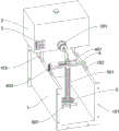
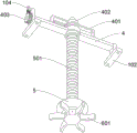
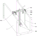
FIG. 1 is a schematic view of the front side structure of the U-shaped drainage channel of the present invention.
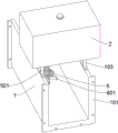
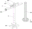
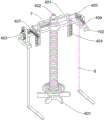
FIG. 2 is a schematic view of the rear side structure of the U-shaped drainage channel of the present invention.
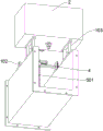
FIG. 3 is a schematic diagram of the bottom structure of the flocculant medicine tank of the present invention.
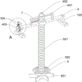
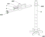
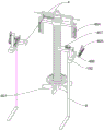
Fig. 4 is a schematic diagram of the rotary installation of the medicine distribution rotary pipe of the invention.
FIG. 5 is a schematic view of the bottom structure of the drug delivery transfer tube of the present invention.
Fig. 6 is a schematic diagram of the structure of the floating body of the present invention.
Figure 7 is a schematic view of the bottom structure of the floating body of the present invention.
Fig. 8 is a schematic view of the structure of the cross-brace mounting plate of the present invention.
FIG. 9 is a schematic diagram of the semi-sectional internal structure of the drug delivery rotary tube of the present invention.
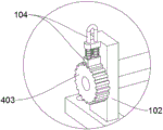
Fig. 10 is an enlarged schematic view of the portion a of fig. 4 according to the present invention.
FIG. 11 is a schematic view of the construction of the cross-brace mounting plate of the present invention.
FIG. 12 is a schematic view of the structure of the blocking remover of the present invention.
Fig. 13 is a schematic view of the structure of the driving rack of the present invention.
List of reference numerals
1. A U-shaped drainage channel; 101. a U-shaped mounting frame; 102. a T-shaped mounting block; 103. a mounting bracket; 104. a plug-in positioning piece; 2. a flocculant medicine box; 201. a dosing pump; 3. an intelligent electric cabinet; 4. a cross support mounting plate; 401. an L-shaped stay bar; 402. a water receiving seat; 403. positioning gears; 404. an L-shaped suspender; 405. a connecting rod; 406. a driving rack; 407. an I-shaped positioning block; 5. a floating body; 501. a threaded telescopic tube; 502. a counterweight ring; 6. a medicine distribution rotary tube; 601. a deflector; 602. a limiting ring; 7. contact wheel type tachometer; 8. and (5) clearing the blocking piece.
Description of the embodiments
In order to make the objects, aspects and advantages of the technical solution of the present invention more clear, the technical solution of the embodiment of the present invention will be clearly and completely described below with reference to the accompanying drawings of the specific embodiment of the present invention.
Embodiment one: please refer to fig. 1 to 10:
the invention provides an intelligent control device for adding a slime water flocculant, which comprises a U-shaped drainage canal 1, wherein two U-shaped mounting frames 101 are symmetrically welded at the front end and the rear end of the U-shaped drainage canal 1, six connecting mounting holes are formed in the two U-shaped mounting frames 101, and the U-shaped drainage canal 1 is connected with a drainage canal pipe of slime water through the two U-shaped mounting frames 101; two mounting brackets 103 are symmetrically supported at the top ends of the left side wall and the right side wall of the rear half section of the U-shaped drainage channel 1 through screw locking, the two mounting brackets 103 are composed of an upper longitudinal supporting mounting plate, a lower longitudinal supporting mounting plate and two longitudinal supporting plates which are welded between the two longitudinal supporting mounting plates in a front-back symmetrical mode, and a flocculant medicine box 2 is fixedly installed at the top ends of the two mounting brackets 103 through screw locking; two T-shaped mounting blocks 102 are symmetrically fixed at the top ends of the middle sections of the left and right side walls of the U-shaped drainage channel 1 through screw locking, and a cross brace mounting plate 4 is rotatably mounted between the top end sections of the two T-shaped mounting blocks 102; two L-shaped supporting rods 401 are symmetrically welded at the top end of the transverse supporting mounting plate 4, and a water receiving seat 402 is welded between the head end sections of the two L-shaped supporting rods 401; a dosing pump 201 is fixed at the middle position of the bottom of the front side wall of the flocculant medicine box 2 through screw locking, and a water outlet nozzle of the dosing pump 201 is rotatably connected with a water receiving seat 402 through a hose; the middle section of the transverse support mounting plate 4 is provided with a medicine distribution rotary pipe 6 in a penetrating and rotating way, the top end section of the medicine distribution rotary pipe 6 is connected with a water receiving seat 402 in a rotating way, and a medicine feeding pump 201 can supply medicine to the rotary medicine distribution rotary pipe 6 through the water receiving seat 402, and the suction supply pressure of the medicine feeding pump 201 is low; a floating body 5 is sleeved on the medicine distribution rotary pipe 6 in a sliding way; an intelligent electric control box 3 is fixedly arranged at the bottom of the left side of the rear side wall of the flocculant medicine box 2, and an intelligent control module is arranged in the intelligent electric control box 3; a contact wheel type tachometer 7 is arranged on the transverse strut on the vertical strut section of the left L-shaped strut 401; a positioning lug block is welded at the top end of the left T-shaped mounting block 102, and a plug-in positioning piece 104 is installed on the positioning lug block in a penetrating and sliding manner through spring pushing; the plugging positioning piece 104 is composed of a U-shaped sliding frame and a U-shaped clamping plate welded at the bottom of the U-shaped sliding frame, wherein the U-shaped sliding frame and the positioning lug block penetrate through and are in sliding fit.
The specific brands of the contact wheel tachometer 7 are: victor/victory; the specific model is as follows: VC6236P
Wherein, two short shafts are symmetrically welded at the left and right ends of the cross brace mounting plate 4, wherein a positioning gear 403 is sleeved on the protruding section of the left short shaft, the U-shaped clamping plate is matched with the positioning gear 403 in a clamping and inserting way, the cross brace mounting plate 4 is rotatably mounted, the medicine distribution rotary pipe 6 can be upwards swung to be taken out from the U-shaped drainage channel 1, the medicine outlet holes are conveniently cleared, the positioning gear 403 can be inserted and fixed by the inserting positioning piece 104, and the medicine distribution rotary pipe 6 is kept in a state of being vertically used in upper swing cleaning and lower swing.
Six drug discharging holes are formed in the outer circumferential wall of the drug distributing rotary pipe 6 in a penetrating mode on a pipe section inside the U-shaped drainage channel 1, the drug distributing rotary pipe 6 is inserted into the U-shaped drainage channel 1 in a rotary mode, flocculating agents can be discharged and added into the coal slime water flowing in the U-shaped drainage channel 1 and with different depths through the six drug discharging holes, uniform mixing of the flocculating agents and the coal slime water flowing in the U-shaped drainage channel 1 is facilitated, subsequent rapid sedimentation and filtration of the coal slime water are facilitated, and through the six guide plates 601, the drug distributing rotary pipe 6 can be driven to rotate by the coal slime water flowing in a pushing mode, the flocculating agents discharged through the six drug discharging holes and the coal slime water are fully and uniformly mixed, and the subsequent sedimentation and filtration speed of the coal slime water is further improved.
Wherein, body 5 wholly is the inside hollow structure of frustum, body 5's top fixed mounting has a counter weight ring 502, counter weight ring 502 multiplicable body 5's gravity, make behind U form water drainage canal 1 inside water level reduces, body 5 can be driven tensile screw thread flexible pipe 501 by the weight, and body 5's top central point puts and is connected with a screw thread flexible pipe 501, body 5 can follow the lift variation adaptation of U form water drainage canal 1 inside water level and slide from top to bottom and drive screw thread flexible pipe 501 to stretch and adjust, shelter from the play medicine hole of exposing the water surface, make the play medicine hole exhaust flocculant of exposing the water surface through screw thread flexible pipe 501 water conservancy diversion downwards and through the slip clearance discharge into the inside implementation intensive mixing of slime water between body 5 and the cloth medicine change pipe 6, avoid the top layer of flocculant discharge in slime water directly after U form water level reduction in water drainage canal 1, influence flocculant and slime water intensive even mixing, and through body 5, screw thread flexible pipe 501 is to the exposure water conservancy diversion control of six discharge medicine holes of different height can completely rely on the water level lift buoyancy to shelter from the manual observation, this is carried out and is convenient to realize the manual flexible pipe of exposing the water diversion to the screw thread is saved.
Wherein, the bottom welding of cloth medicine changes pipe 6 has a water spray dish, encircle the welding on the water spray dish and has six guide vanes 601 that the arc set up, and the position that is located between six guide vanes 601 on the circumference outer wall of water spray dish is encircleed and is run through and have been seted up six medicine holes, when U form water drainage canal 1 inside water level is lower, body 5 and flexible pipe of screw thread 501 slip are arranged in the bottom of cloth medicine changes pipe 6 and with six discharge medicine hole totally seal and keep off (refer to fig. 4), six medicine holes between six guide vanes 601 can implement the emission to the flocculating agent this moment and guarantee that the coal slime water of low water level state also can be mixed with the flocculating agent.
Wherein, the top end section of the medicine distribution rotary tube 6 is welded with a big limit ring 602 and a small limit ring 602 at intervals up and down, and the two limit rings 602 are rotationally attached to the middle part of the transverse support mounting plate 4; the threaded telescopic pipe 501 is matched with the medicine distribution rotary pipe 6 in a sliding sleeve manner, and the top end of the threaded telescopic pipe 501 is fixedly connected with the limiting ring 602 at the lower side.
The front end speed measuring wheel of the contact wheel type tachometer 7 is in abutting contact with the upper limit ring 602, the contact wheel type tachometer 7 is electrically connected with the dosing pump 201 through the intelligent control module, the intelligent control module can control the rotating speed of the dosing pump 201 according to the change of the rotating speed of the dosing rotating pipe 6 detected by the contact wheel type tachometer 7, when the rotating speed of the dosing rotating pipe 6 is increased, the flow rate of the slime water in the U-shaped drainage canal 1 is larger and the flow rate is higher, at the moment, the intelligent control module can increase the rotating speed of the dosing pump 201 to increase the pumping adding amount of the flocculant, and when the rotating speed of the dosing rotating pipe 6 is reduced, the intelligent control module is opposite, and further the invention can intelligently increase and decrease the adding amount of the flocculant according to the size of the discharging flow rate of the slime water, and compared with the adding equipment for quantitatively pumping and adding the flocculant for a long time, the excessive waste of the flocculant can be reduced.
Embodiment two: please refer to fig. 11 to 13:
the invention provides an intelligent control device for adding a slime water flocculant, which comprises a cross brace mounting plate 4, an L-shaped suspender 404, a connecting rod 405, a driving rack 406, an I-shaped positioning block 407 and a blockage clearing piece 8; the whole transverse support mounting plate 4 is arranged in three sections, wherein the left section and the right section are shorter, the middle section is longer, and the left section and the right section are respectively in running fit with the two T-shaped mounting blocks 102; two L-shaped suspenders 404 are symmetrically welded at the bottoms of the left end and the right end of the middle section of the cross brace mounting plate 4, two sliding shafts are symmetrically and upwards welded on the horizontal parts of the two L-shaped suspenders 404, and the two sliding shafts are in penetrating sliding fit with the left end section and the right end section of the cross brace mounting plate 4 through spring pushing;
the left section and the right section of the transverse support mounting plate 4 are symmetrically and rotatably provided with two blocking clearing pieces 8 with L-shaped structures, the bottom sides of the horizontal parts of the two blocking clearing pieces 8 are fixedly provided with brushes through magic tapes, and the protruding sections at the top ends of the vertical support parts of the two blocking clearing pieces 8 are sleeved with two driven gears; two I-shaped positioning blocks 407 are symmetrically welded at the top ends of the left section and the right section of the transverse support mounting plate 4, two driving racks 406 are symmetrically and slidably arranged on the two I-shaped positioning blocks 407, a strip-shaped groove is formed in the driving racks 406, and the strip-shaped groove is in sliding fit with the I-shaped positioning blocks 407;
two positioning shafts are welded in the two strip-shaped grooves and are in penetrating sliding fit with two I-shaped positioning blocks 407 through spring pushing, two connecting rods 405 are symmetrically and rotationally connected to the left side and the right side of the two L-shaped supporting rods 401, and the tail ends of the two connecting rods 405 are rotationally connected with the head ends of two driving racks 406; the two driving racks 406 are correspondingly meshed with the two driven gears.
The middle section of the cross brace mounting plate 4 is penetrated and rotatably provided with a medicine distribution rotary pipe 6, the middle section of the cross brace mounting plate 4 is in sliding fit with the left section and the right section of the cross brace mounting plate 4 through two sliding shafts, when the coal slime water in the U-shaped drainage canal 1 is less, the water level is lower and the flow velocity is slower, settled coal slime can be trapped in the bottom space of the U-shaped drainage canal 1, especially in the position of the guide vane 601, the rotation of the guide vane 601 is blocked, the medicine distribution rotary pipe 6 is disabled due to the rotation of the medicine distribution rotary pipe 6, the middle section of the cross brace mounting plate 4, the medicine distribution rotary pipe 6 and the six guide vanes 601 can be driven by the two hand-held L-shaped support rods 401 to vertically slide and impact to tremble and loosen the settled coal slime at the bottom of the guide vane 601, so that the loosened coal slime can be dispersed and carried away by water flow, the blockage is removed for the guide vane 601, the rotation medicine distribution rotary function of the medicine distribution rotary pipe 6 is restored, in addition, the two blocking clearing pieces 8 can swing reciprocally to implement auxiliary brushing and cleaning on the coal slime gathered at the positions of the six guide plates 601, the cleaning piece can be used together with the vibration impact fit of the six guide plates 601 to implement more thorough cleaning on the settled coal slime, the blocking clearing effect on the guide plates 601 is better, in addition, the two L-shaped supporting rods 401, the two connecting rods 405 and the two driving racks 406 are jointly connected to form two crank-slider mechanisms, and through the two mechanisms, the middle section of the transverse support mounting plate 4 and the medicine distribution rotary tube 6 can be driven to slide forwards and backwards in a linkage manner, and the two driven gears and the two blocking clearing pieces 8 are driven to implement positive and negative rotation, so that the trouble that the two blocking clearing pieces 8 are driven by additional manual force during the blocking clearing operation is omitted.
The first embodiment is used in the following manner and functions: in the invention, the medicine feeding pump 201 can feed medicine to the rotary medicine distribution rotary pipe 6 through the water receiving seat 402, the suction supply pressure of the medicine feeding pump 201 is small, the medicine distribution rotary pipe 6 is rotationally inserted into the U-shaped drainage canal 1, and the flocculant can be discharged and added into the coal slime water flowing in the U-shaped drainage canal 1 at different depths through six medicine discharge holes on the medicine distribution rotary pipe 6, so that the flocculant and the coal slime water flowing in a discharging way can be uniformly mixed, and the medicine distribution rotary pipe 6 can be driven to rotate by the coal slime water flowing in a discharging way through six guide plates 601, so that the flocculant discharged from six medicine discharge holes on the medicine distribution rotary pipe can be fully and uniformly mixed with the coal slime water;
the floating body 5 can slide up and down along with the lifting change of the water level in the U-shaped drainage canal 1 and drives the threaded telescopic pipe 501 to stretch and adjust, the medicine outlet hole exposing the water surface is shielded, the flocculating agent discharged by the medicine outlet hole exposing the water surface is downwards guided by the threaded telescopic pipe 501 and is discharged into the interior of the slime water through the sliding gap between the floating body 5 and the medicine distribution rotary pipe 6 to be fully mixed, and the weight ring 502 can increase the gravity of the floating body 5, so that after the water level in the U-shaped drainage canal 1 is lowered, the floating body 5 can be driven by heavy pressure to stretch the threaded telescopic pipe 501 to slide downwards;
when the water level in the U-shaped drainage canal 1 is low, the floating body 5 and the threaded telescopic pipe 501 are arranged at the bottommost part of the medicine distribution rotary pipe 6 in a sliding manner and seal all six medicine discharge holes, at the moment, six medicine discharge holes between six guide plates 601 can discharge flocculating agents to ensure that coal slime water in a low water level state can be mixed with the flocculating agents;
the intelligent control module can control the rotation speed of the dosing pump 201 according to the change of the rotation speed of the dosing rotary pipe 6 detected by the contact wheel type rotation speed meter 7, when the rotation speed of the dosing rotary pipe 6 is increased, the flow of the slime water in the U-shaped drainage channel 1 is larger and the flow speed is higher, at this time, the intelligent control module can increase the rotation speed of the dosing pump 201 to increase the suction adding amount of the flocculant, and when the rotation speed of the dosing rotary pipe 6 is reduced, the flow speed is opposite.
Claims (10)
1. An intelligent control device for adding a slime water flocculant, which is characterized by comprising: the U-shaped drainage canal (1), wherein two mounting brackets (103) are symmetrically supported at the top end of the U-shaped drainage canal (1) through screw locking, and a flocculant medicine box (2) is fixedly arranged at the top ends of the two mounting brackets (103) through screw locking; two T-shaped mounting blocks (102) are symmetrically fixed at the top ends of the left side wall and the right side wall of the U-shaped drainage channel (1) through screw locking, and a cross brace mounting plate (4) is rotatably mounted between the top end sections of the two T-shaped mounting blocks (102); two L-shaped supporting rods (401) are symmetrically welded at the top end of the transverse supporting mounting plate (4), and a water receiving seat (402) is welded between the head end sections of the two L-shaped supporting rods (401); a dosing pump (201) is fixedly locked at the middle position of the bottom of the front side wall of the flocculant medicine box (2) through a screw, and a water outlet nozzle of the dosing pump (201) is rotationally connected with a water receiving seat (402) through a hose; a medicine distribution rotary pipe (6) is rotatably installed on the middle section of the cross support mounting plate (4) in a penetrating way, and the top end section of the medicine distribution rotary pipe (6) is rotatably connected with the water receiving seat (402); a floating body (5) is sleeved on the medicine distribution rotating pipe (6) in a sliding way; an intelligent electric control box (3) is fixedly arranged at the bottom of the left side of the rear side wall of the flocculant medicine box (2), and an intelligent control module is arranged in the intelligent electric control box (3); the left side of the vertical support section of the L-shaped support rod (401) is provided with a contact wheel type tachometer (7) by a transverse support.
2. The intelligent control device for adding the slime water flocculant according to claim 1, wherein: the top end of the T-shaped mounting block (102) on the left side is welded with a positioning lug block, and the positioning lug block is provided with a plug-in positioning piece (104) penetrating and sliding through the spring pushing.
3. The intelligent control device for adding the slime water flocculant according to claim 2, wherein: the plug-in positioning piece (104) is composed of a U-shaped sliding frame and a U-shaped clamping plate welded at the bottom of the U-shaped sliding frame, wherein the U-shaped sliding frame and the positioning lug block penetrate through and are in sliding fit.
4. An intelligent control device for adding a slime water flocculant as claimed in claim 3, wherein: two short shafts are symmetrically welded at the left end and the right end of the transverse support mounting plate (4), a positioning gear (403) is sleeved on the protruding section of the left short shaft, and the U-shaped clamping plate is in clamping fit with the positioning gear (403).
5. The intelligent control device for adding the slime water flocculant according to claim 1, wherein: six drug discharging holes are formed in the outer wall of the circumference of the drug distribution rotary pipe (6) in a penetrating mode on the pipe section inside the U-shaped drainage channel (1).
6. The intelligent control device for adding the slime water flocculant according to claim 1, wherein: the bottom of the medicine distribution rotary pipe (6) is welded with a water spray disc, six guide plates (601) arranged in an arc shape are welded on the water spray disc in a surrounding mode, and six medicine outlet holes are formed in the circumferential outer wall of the water spray disc in a surrounding and penetrating mode at positions between the six guide plates (601).
7. The intelligent control device for adding the slime water flocculant according to claim 1, wherein: the floating body (5) is integrally of a hollow structure in the frustum, a counterweight ring (502) is fixedly arranged at the top end of the floating body (5), and a threaded telescopic pipe (501) is connected to the center of the top end of the floating body (5).
8. The intelligent control device for adding the slime water flocculant according to claim 7, wherein: the top end section of the medicine distribution rotary pipe (6) is welded with a big limit ring (602) and a small limit ring (602) at intervals up and down, and the two limit rings (602) are rotationally attached to the middle part of the transverse support mounting plate (4).
9. The intelligent control device for adding the slime water flocculant according to claim 8, wherein: the threaded telescopic tube (501) is matched with the medicine distribution rotary tube (6) in a sliding sleeve mode, and the top end of the threaded telescopic tube (501) is fixedly connected with the limiting ring (602) at the lower side.
10. The intelligent control device for adding the slime water flocculant according to claim 8, wherein: the head end speed measuring wheel of the contact wheel type tachometer (7) is in abutting contact with the upper limit ring (602), and the contact wheel type tachometer (7) is electrically connected with the dosing pump (201) through the intelligent control module.
Priority Applications (1)
| Application Number | Priority Date | Filing Date | Title |
|---|---|---|---|
| CN202310360865.8A CN116332306A (en) | 2023-04-06 | 2023-04-06 | Intelligent control device for adding coal slime water flocculant |
Applications Claiming Priority (1)
| Application Number | Priority Date | Filing Date | Title |
|---|---|---|---|
| CN202310360865.8A CN116332306A (en) | 2023-04-06 | 2023-04-06 | Intelligent control device for adding coal slime water flocculant |
Publications (1)
| Publication Number | Publication Date |
|---|---|
| CN116332306A true CN116332306A (en) | 2023-06-27 |
Family
ID=86876036
Family Applications (1)
| Application Number | Title | Priority Date | Filing Date |
|---|---|---|---|
| CN202310360865.8A Pending CN116332306A (en) | 2023-04-06 | 2023-04-06 | Intelligent control device for adding coal slime water flocculant |
Country Status (1)
| Country | Link |
|---|---|
| CN (1) | CN116332306A (en) |
Cited By (1)
| Publication number | Priority date | Publication date | Assignee | Title |
|---|---|---|---|---|
| CN117585781A (en) * | 2024-01-18 | 2024-02-23 | 北京建筑大学 | Sewage treatment equipment and method based on automatic flocculant addition |
-
2023
- 2023-04-06 CN CN202310360865.8A patent/CN116332306A/en active Pending
Cited By (2)
| Publication number | Priority date | Publication date | Assignee | Title |
|---|---|---|---|---|
| CN117585781A (en) * | 2024-01-18 | 2024-02-23 | 北京建筑大学 | Sewage treatment equipment and method based on automatic flocculant addition |
| CN117585781B (en) * | 2024-01-18 | 2024-04-05 | 北京建筑大学 | Sewage treatment equipment and method based on automatic flocculant addition |
Similar Documents
| Publication | Publication Date | Title |
|---|---|---|
| CN116332306A (en) | Intelligent control device for adding coal slime water flocculant | |
| CN111764361B (en) | Comprehensive cleaning method for pump station forebay | |
| CN111732274A (en) | Biological purification system for treating black and odorous water body in river channel | |
| CN210797479U (en) | Water diversion irrigation facility for reservoir dam body | |
| CN209643434U (en) | A kind of vertical greening system of wall greening | |
| CN114293606B (en) | Deep cleaning construction method for channel side slope | |
| CN217017829U (en) | Cleaning device for graphite silicon carbide crucible | |
| CN111764362B (en) | Pump station forebay is synthesized and is decontaminated equipment | |
| CN216223560U (en) | Construction site dust device for building engineering | |
| CN215876357U (en) | Pump suction type suction dredge | |
| CN214485907U (en) | Groundwater pollution treatment device | |
| CN215947795U (en) | Pitch laying device that town road was used | |
| CN214282593U (en) | Irrigation equipment is used to forestry trees | |
| CN211960090U (en) | Adjustable shower nozzle economizes on type liquid manure medicine integration machine | |
| CN209134820U (en) | A kind of pump sucking automatic flushing device | |
| CN113700129A (en) | Sewage pipeline inner wall descaling device for municipal sewage treatment | |
| CN221355282U (en) | Pig house manure cleaning device in pig farm | |
| CN112049172A (en) | Water conservancy river course is maintained and is used sediment removal device | |
| CN218354306U (en) | Sprayer capable of preventing liquid medicine from splashing | |
| CN217972272U (en) | Garbage grab bucket bridge crane | |
| CN221710422U (en) | Pit digging device | |
| CN211898262U (en) | Circulating tooth harrow trash cleaning machine | |
| CN221283776U (en) | Anti-blocking drip irrigation device | |
| CN117023738B (en) | Coking wastewater processor | |
| CN206622378U (en) | A kind of Paris polyphylla cleaning device |
Legal Events
| Date | Code | Title | Description |
|---|---|---|---|
| PB01 | Publication | ||
| PB01 | Publication | ||
| SE01 | Entry into force of request for substantive examination | ||
| SE01 | Entry into force of request for substantive examination |