CN116267258A - Speed-adjustable hay cutting and silk kneading machine - Google Patents
Speed-adjustable hay cutting and silk kneading machine Download PDFInfo
- Publication number
- CN116267258A CN116267258A CN202310019504.7A CN202310019504A CN116267258A CN 116267258 A CN116267258 A CN 116267258A CN 202310019504 A CN202310019504 A CN 202310019504A CN 116267258 A CN116267258 A CN 116267258A
- Authority
- CN
- China
- Prior art keywords
- shaft
- fixedly connected
- wheel
- frame
- sleeved
- Prior art date
- Legal status (The legal status is an assumption and is not a legal conclusion. Google has not performed a legal analysis and makes no representation as to the accuracy of the status listed.)
- Pending
Links
- 238000004898 kneading Methods 0.000 title claims abstract description 45
- 230000005540 biological transmission Effects 0.000 claims description 25
- 239000002994 raw material Substances 0.000 abstract description 11
- 239000010902 straw Substances 0.000 abstract description 10
- 239000002184 metal Substances 0.000 abstract description 4
- 241000196324 Embryophyta Species 0.000 description 29
- 230000001105 regulatory effect Effects 0.000 description 15
- 239000000463 material Substances 0.000 description 8
- 244000025254 Cannabis sativa Species 0.000 description 6
- 238000010586 diagram Methods 0.000 description 4
- 230000033001 locomotion Effects 0.000 description 4
- 238000006073 displacement reaction Methods 0.000 description 3
- 230000001681 protective effect Effects 0.000 description 3
- 230000006835 compression Effects 0.000 description 2
- 238000007906 compression Methods 0.000 description 2
- 238000007599 discharging Methods 0.000 description 2
- 238000009434 installation Methods 0.000 description 2
- 238000012423 maintenance Methods 0.000 description 2
- 239000002028 Biomass Substances 0.000 description 1
- 229920000742 Cotton Polymers 0.000 description 1
- 230000004888 barrier function Effects 0.000 description 1
- 238000010009 beating Methods 0.000 description 1
- 230000009286 beneficial effect Effects 0.000 description 1
- 230000008859 change Effects 0.000 description 1
- 238000000034 method Methods 0.000 description 1
- 238000012986 modification Methods 0.000 description 1
- 230000004048 modification Effects 0.000 description 1
- 230000008569 process Effects 0.000 description 1
Images
Classifications
-
- A—HUMAN NECESSITIES
- A01—AGRICULTURE; FORESTRY; ANIMAL HUSBANDRY; HUNTING; TRAPPING; FISHING
- A01F—PROCESSING OF HARVESTED PRODUCE; HAY OR STRAW PRESSES; DEVICES FOR STORING AGRICULTURAL OR HORTICULTURAL PRODUCE
- A01F29/00—Cutting apparatus specially adapted for cutting hay, straw or the like
- A01F29/02—Cutting apparatus specially adapted for cutting hay, straw or the like having rotating knives with their cutting edges in a plane perpendicular to their rotational axis
- A01F29/025—Cutting apparatus specially adapted for cutting hay, straw or the like having rotating knives with their cutting edges in a plane perpendicular to their rotational axis with feeding direction parallel to axis
-
- A—HUMAN NECESSITIES
- A01—AGRICULTURE; FORESTRY; ANIMAL HUSBANDRY; HUNTING; TRAPPING; FISHING
- A01F—PROCESSING OF HARVESTED PRODUCE; HAY OR STRAW PRESSES; DEVICES FOR STORING AGRICULTURAL OR HORTICULTURAL PRODUCE
- A01F29/00—Cutting apparatus specially adapted for cutting hay, straw or the like
- A01F29/08—Cutting apparatus specially adapted for cutting hay, straw or the like having reciprocating knives
-
- A—HUMAN NECESSITIES
- A01—AGRICULTURE; FORESTRY; ANIMAL HUSBANDRY; HUNTING; TRAPPING; FISHING
- A01F—PROCESSING OF HARVESTED PRODUCE; HAY OR STRAW PRESSES; DEVICES FOR STORING AGRICULTURAL OR HORTICULTURAL PRODUCE
- A01F29/00—Cutting apparatus specially adapted for cutting hay, straw or the like
- A01F29/09—Details
- A01F29/095—Mounting or adjusting of knives
-
- A—HUMAN NECESSITIES
- A01—AGRICULTURE; FORESTRY; ANIMAL HUSBANDRY; HUNTING; TRAPPING; FISHING
- A01F—PROCESSING OF HARVESTED PRODUCE; HAY OR STRAW PRESSES; DEVICES FOR STORING AGRICULTURAL OR HORTICULTURAL PRODUCE
- A01F29/00—Cutting apparatus specially adapted for cutting hay, straw or the like
- A01F29/09—Details
- A01F29/10—Feeding devices
-
- Y—GENERAL TAGGING OF NEW TECHNOLOGICAL DEVELOPMENTS; GENERAL TAGGING OF CROSS-SECTIONAL TECHNOLOGIES SPANNING OVER SEVERAL SECTIONS OF THE IPC; TECHNICAL SUBJECTS COVERED BY FORMER USPC CROSS-REFERENCE ART COLLECTIONS [XRACs] AND DIGESTS
- Y02—TECHNOLOGIES OR APPLICATIONS FOR MITIGATION OR ADAPTATION AGAINST CLIMATE CHANGE
- Y02P—CLIMATE CHANGE MITIGATION TECHNOLOGIES IN THE PRODUCTION OR PROCESSING OF GOODS
- Y02P60/00—Technologies relating to agriculture, livestock or agroalimentary industries
- Y02P60/14—Measures for saving energy, e.g. in green houses
Landscapes
- Life Sciences & Earth Sciences (AREA)
- Environmental Sciences (AREA)
- Crushing And Pulverization Processes (AREA)
Abstract
The invention discloses a speed-adjustable hay cutter silk-kneading machine, which comprises a frame, a base and a motor, wherein the frame is provided with a plurality of blades; a base is fixedly connected to the frame; a motor is fixedly connected to the base; the output shaft of the motor is fixedly connected with a first wheel; a first belt is sleeved on the first wheel; the other end of the first belt is inserted with a second wheel; the second wheel is fixedly connected with a first shaft; the wire kneading machine is assembled through the external sheet metal protection cover, then pushes plants into the pressing roller, then is cut and crushed by the cutting knife and the crushing blade, then is manually held to push the wrench when the speed needs to be adjusted, and then is changed into the engagement of the second main gear and the second auxiliary gear by switching the engagement of the first main gear and the first auxiliary gear, so that the rotating speed of the pressing roller is improved, the plant raw materials can be rapidly cut and crushed, the length of the cut plant straws is adjusted, and the problem that the cutting speed and the cutting length are inconvenient in adjustment of the existing cutting machine is solved.
Description
Technical Field
The invention relates to the field of silk kneading machines, in particular to a speed-adjustable hay cutting silk kneading machine.
Background
The straw rubbing machine is mainly used for shredding plant straws with diameters of less than 2CM, such as cotton stalks, branches, barks, straws and the like, and can also be used for shredding various crop straws and pastures, and the purpose is to form biomass in a shredding state, so that the subsequent process is convenient to use.
Chinese application patent CN216362672U discloses a hay cutter and silk kneading machine, which comprises a frame, a feed inlet, a discharge outlet, a hay cutter chamber and a silk kneading chamber, wherein: the feeding port, the discharging port, the grass cutting chamber and the wire kneading chamber are all arranged on the frame, the feeding port is arranged at the front part of the grass cutting chamber, the wire kneading chamber is arranged at the rear part of the grass cutting chamber, the grass cutting chamber is communicated with the wire kneading chamber, and the discharging port is arranged at the rear part of the wire kneading chamber; a movable cutter and a fixed cutter are arranged in the grass cutting chamber, and a hammer sheet is arranged in the yarn kneading chamber; the hay cutter and silk kneading machine further comprises a sieve plate and a locking device, wherein the sieve plate is rotatably arranged at the rear outlet of the silk kneading chamber and is locked through the locking device.
The existing hay cutting and silk kneading machine controls the speed of conveying raw materials and the cutting length through a plurality of power units, so that when the running speed needs to be regulated, the rotating speed of a regulating motor needs to be regulated for more than once, so that the conveying speed and the cutting speed are matched, the cutting efficiency is improved while the cut crop length is ensured to be accurate, and the efficiency of switching the working modes of the silk kneading machine is low.
Disclosure of Invention
The invention aims to solve the technical problems and provides a speed-adjustable hay cutter silk kneading machine.
In order to achieve the above object, the present invention is realized by the following technical scheme;
the technical scheme adopted for solving the technical problems is as follows: the invention relates to a speed-adjustable hay cutter silk-kneading machine, which comprises a frame, a base and a motor; a base is fixedly connected to the frame; a motor is fixedly connected to the base; the output shaft of the motor is fixedly connected with a first wheel; a first belt is sleeved on the first wheel; the other end of the first belt is inserted with a second wheel; the second wheel is fixedly connected with a first shaft; the first shaft is rotationally inserted on the frame; the first shaft is sleeved with a third wheel and a tool rest; a plurality of cutting knives are obliquely and fixedly connected to the knife rest; a second belt is sleeved on the third wheel; the second belt is internally meshed and inserted with a fourth wheel; a second shaft is fixedly connected in the fourth wheel; a plurality of crushing blades are fixedly connected on the second shaft; an anti-slip square tube is sleeved on the first shaft in a sliding manner; a first main gear and a second main gear are fixedly connected on the anti-skid square tube at intervals; an adjusting plate is fixedly connected to the frame; a wrench is movably inserted on the adjusting plate; a third shaft is rotationally inserted into the frame; the third shaft is fixedly connected with a pressing roller; a first slave gear and a second slave gear are fixedly connected to one end of the third shaft; during operation, the wire kneading machine is assembled through external panel beating safety cover, then push the plant into the pressure roller, then cut by cutting knife and crushing blade and smash, then when needs are adjusted the speed, the spanner is held to the manual hand-held and is promoted, then make the meshing of switching first master gear and first slave gear become the meshing of second master gear and second slave gear, thereby the rotational speed that makes the pressure roller is improved, thereby make the plant raw materials can be quick cut and smash, and adjusted the length of cutting plant straw simultaneously, the inconvenient problem of current hay cutting wire kneading machine regulation cutting speed and cutting length has been solved.
Further, the other end of the third shaft is sleeved with a third belt; a fourth shaft is inserted into the other end of the third belt; the fourth shaft is rotatably connected in the frame; the fourth shaft is fixedly connected with a first transmission shaft; a plurality of chains are engaged and sleeved on the first transmission shaft; a plurality of support plates are fixedly connected to the chain at intervals; the other end of the chain is connected with a second transmission shaft in a meshed and spliced manner; side wing plates are symmetrically sleeved on the second transmission shaft; during operation, the plant raw materials can be smoothly advanced without being accurately placed in the middle position of the supporting plate by the symmetrically inclined side wing plates; the rotation of the third shaft can be transmitted to the fourth shaft through the third belt, so that the functions of driving by using one power source and conveniently adjusting speed are realized.
Furthermore, positioning blocks are symmetrically and fixedly connected on the side wing plates; a pull ring is inserted into the positioning block; the pull rings are sleeved at two ends of the second transmission shaft; a nut is sleeved on the pull ring corresponding to the positioning block in a threaded manner; when the device works, the position of the second transmission shaft on the pull ring is changed by rotating the nut, so that the second transmission shaft can be tightened, and the device is convenient to install and debug.
Furthermore, the frame is symmetrically and fixedly connected with a protection plate; the protection plate is provided with an adjusting groove corresponding to the spanner; during operation, through the displacement of adjustment tank restriction spanner for the adjustment position of spanner is restricted, thereby makes the meshing of switching first master gear and first slave gear and the meshing transmission of second master gear and second slave gear more reliable and stable, makes the rotation speed of pressing roller, chain and backup pad can adjust, thereby switches different cutting length and cutting speed, has solved the inconvenient quick problem of current wire kneading machine switching speed.
Further, a safety baffle is connected between the protection plates in a pin manner; the safety baffle is provided with a handle groove; a guide plate is connected between the side wing plates through pins; during operation, the safety baffle connected by the pin is convenient to rotate for one hundred and eighty degrees for opening, so that the overhaul is convenient; the plant raw material tilting moving along the supporting plate is pressed down through the guide plate, so that the plant raw material is conveniently pressed by the pressing roller to be compressed and cut off by the follow-up cutting knife, and the cutting function can be operated normally.
Further, the frame is symmetrically and rotatably connected with two groups of rollers; a protective plate is connected between the side wing plates through pins; when the silk kneading machine works, the two groups of rollers are symmetrically and rotationally connected on the frame, so that the silk kneading machine is convenient for short-distance movement; through the pin connection has the protection shield between the flank board for the one end of the conveyer belt that chain and backup pad formed is blocked, thereby makes when the manual work places the plant, can once put on the surface of conveyer belt, thereby can not insert and cause the jam between chain and the backup pad, makes the plant can be smooth remove along with the conveyer belt, has solved current wire kneading machine material loading and has inserted easily in the conveyer belt when putting into the conveyer belt and cause the jam.
The speed-adjustable hay cutter silk kneading machine provided by the invention has the following beneficial effects:
1. according to the invention, the wire kneading machine is assembled through the external sheet metal protection cover, plants are pushed into the pressing roller, then cut and crushed by the cutting knife and the crushing blade, then the spanner is manually held to push the wire kneading machine when the speed needs to be regulated, and then the engagement of the first main gear and the first auxiliary gear is changed into the engagement of the second main gear and the second auxiliary gear, so that the rotating speed of the pressing roller is increased, the plant raw materials can be rapidly cut and crushed, the length of the cut plant straws is regulated, and the problems that the conventional straw cutting wire kneading machine is inconvenient in regulating the cutting speed and the cutting length are solved;
2. according to the invention, by the symmetrically inclined side wing plates, plant raw materials can be smoothly advanced without being accurately placed in the middle position of the supporting plate when being placed; the rotation of the third shaft can be transmitted to the fourth shaft through the third belt, so that the functions of driving by using one power source and conveniently adjusting speed are realized.
Drawings
The following describes the embodiments of the present invention in further detail with reference to the drawings;
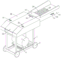
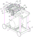
FIG. 1 is a schematic diagram of a first isometric side perspective view of a speed-adjustable hay cutter wire machine;
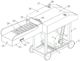
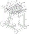
FIG. 2 is a schematic diagram of a second isometric side perspective of a speed-adjustable hay cutter wire-kneading machine;
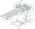
FIG. 3 is a schematic view of a first internal perspective structure of a speed-adjustable hay cutter and kneader;
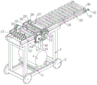
FIG. 4 is a schematic diagram of a second internal perspective view of a speed-adjustable hay cutter wire cutter;
FIG. 5 is a schematic view of a third internal perspective structure of a speed-adjustable hay cutter wire kneading machine;
fig. 6 is a schematic diagram of a fourth internal perspective structure of a speed-adjustable hay cutter and kneader.
The reference numerals in the figures illustrate: 1. a frame; 2. a roller; 3. a base; 4. a motor; 5. a first wheel; 6. a first belt; 7. a second wheel; 8. a first shaft; 9. a third wheel; 10. a second belt; 11. a fourth wheel; 12. a second shaft; 13. a crushing blade; 14. a tool holder; 15. a cutting knife; 16. an anti-slip square tube; 17. a first main gear; 18. a second main gear; 19. an adjusting plate; 20. a wrench; 21. a first slave gear; 22. a second slave gear; 23. a third shaft; 24. pressing rollers; 25. a third belt; 26. a fourth shaft; 27. a first drive shaft; 28. a chain; 29. a support plate; 30. a second drive shaft; 31. a pull ring; 32. a positioning block; 33. a side wing plate; 34. a protective plate; 35. a guide plate; 36. a protection plate; 37. an adjustment tank; 38. a safety barrier; 39. a handle groove.
Detailed Description
It should be understood that the specific embodiments described herein are for purposes of illustration only and are not intended to limit the scope of the invention.
The following description of the technical solutions in the embodiments of the present invention will be made clearly and completely with reference to the accompanying drawings in the embodiments of the present invention, and it is apparent that the described embodiments are only some embodiments of the present invention, not all embodiments. All other embodiments, which can be made by those skilled in the art based on the embodiments of the invention without making any inventive effort, are intended to be within the scope of the invention.
It should be noted that, in the embodiments of the present invention, all directional indicators (such as up-down-left-right-front-rear … …) are merely used to explain the relative positional relationship between the components, motion, etc. in a specific posture (as shown in the drawings), if the specific posture is changed, the directional indicators correspondingly change, and the connection may be a direct connection or an indirect connection.
Referring to fig. 1-6, a speed-adjustable hay cutter and kneader comprises a frame 1, a base 3 and a motor 4; a base 3 is fixedly connected to the frame 1; a motor 4 is fixedly connected to the base 3; the output shaft of the motor 4 is fixedly connected with a first wheel 5; a first belt 6 is sleeved on the first wheel 5; the other end of the first belt 6 is inserted with a second wheel 7; a first shaft 8 is fixedly connected to the second wheel 7; the first shaft 8 is rotatably inserted on the frame 1; the first shaft 8 is sleeved with a third wheel 9 and a tool rest 14; a plurality of cutting knives 15 are obliquely and fixedly connected to the knife rest 14; a second belt 10 is sleeved on the third wheel 9; a fourth wheel 11 is inserted in the second belt 10 in a meshed manner; a second shaft 12 is fixedly connected in the fourth wheel 11; a plurality of crushing blades 13 are fixedly connected to the second shaft 12; an anti-slip square tube 16 is sleeved on the first shaft 8 in a sliding manner; a first main gear 17 and a second main gear 18 are fixedly connected on the anti-skid square tube 16 at intervals; an adjusting plate 19 is fixedly connected to the frame 1; a spanner 20 is movably inserted on the adjusting plate 19; a third shaft 23 is rotatably inserted in the frame 1; a pressing roller 24 is fixedly connected to the third shaft 23; one end of the third shaft 23 is fixedly connected with a first slave gear 21 and a second slave gear 22; during operation, the wire kneading machine is assembled through the external sheet metal protection cover, then the plant is pushed into the pressing roller 24, then the plant is cut and crushed by the cutting knife 15 and the crushing blade 13, then when the speed needs to be adjusted, the wrench 20 is manually held to push the plant, then the engagement of the first main gear 17 and the first auxiliary gear 21 is changed into the engagement of the second main gear 18 and the second auxiliary gear 22, so that the rotating speed of the pressing roller 24 is increased, the plant raw material can be rapidly cut and crushed, the length of the cut plant straw is adjusted, and the problem that the cutting speed and the cutting length are inconvenient in adjustment of the conventional grass cutting wire kneading machine is solved.
The other end of the third shaft 23 is sleeved with a third belt 25; the other end of the third belt 25 is inserted with a fourth shaft 26; the fourth shaft 26 is rotatably connected in the frame 1; the fourth shaft 26 is fixedly connected with a first transmission shaft 27; a plurality of chains 28 are engaged and sleeved on the first transmission shaft 27; a plurality of support plates 29 are fixedly connected on the chain 28 at intervals; the other end of the chain 28 is connected with a second transmission shaft 30 in a meshed and spliced manner; the second transmission shaft 30 is symmetrically sleeved with a side wing plate 33; in operation, plant materials can be smoothly advanced without being precisely placed in the middle position of the supporting plate 29 by the symmetrically inclined side wing plates 33; the rotation of the third shaft 23 can be transmitted to the fourth shaft 26 through the third belt 25, so that the functions of driving by using one power source and conveniently adjusting the speed are realized.
The side wing plates 33 are symmetrically and fixedly connected with positioning blocks 32; a pull ring 31 is inserted into the positioning block 32; the pull rings 31 are sleeved at two ends of the second transmission shaft 30; a nut is sleeved on the pull ring 31 in a threaded manner corresponding to the positioning block 32; in operation, the position of the second transmission shaft 30 on the pull ring 31 is changed by rotating the nut, so that the second transmission shaft 30 can be tightened, and the installation and the debugging are convenient.
The frame 1 is symmetrically and fixedly connected with a protection plate 36; an adjusting groove 37 is formed in the protection plate 36 corresponding to the wrench 20; during operation, the displacement of the wrench 20 is limited by the regulating groove 37, so that the regulating position of the wrench 20 is limited, the meshing transmission of the first main gear 17 and the first auxiliary gear 21 and the meshing transmission of the second main gear 18 and the second auxiliary gear 22 are switched, the rotation speeds of the pressing roller 24, the chain 28 and the supporting plate 29 can be regulated, different cutting lengths and cutting speeds are switched, and the problem that the switching speed of the traditional wire kneading machine is inconvenient and rapid is solved.
A safety shield 38 is pinned between the guard plates 36; the safety baffle 38 is provided with a handle groove 39; a guide plate 35 is connected between the side wing plates 33 in a pin manner; in operation, the safety shield 38 is connected by a pin, so that the safety shield can be conveniently rotated for one hundred eighty degrees to be opened, thereby being convenient for maintenance; the plant material moving along the support plate 29 is tilted and pressed down by the guide plate 35, so that the pressing compression by the pressing roller 24 is conveniently cut off by the subsequent cutter 15, and the cutting function can be normally operated.
Two groups of rollers 2 are symmetrically and rotatably connected to the frame 1; a protective plate 34 is connected between the side wing plates 33 in a pin manner; when the silk kneading machine works, two groups of rollers 2 are symmetrically and rotationally connected on the frame 1, so that the silk kneading machine is convenient for short-distance movement; through the pin connection between the flank plate 33 has the protection shield 34 for the one end of the conveyer belt that chain 28 and backup pad 29 formed is blocked, thereby makes when the manual work places the plant, can once put on the surface of conveyer belt, thereby can not insert between chain 28 and the backup pad 29 and cause the jam, makes the plant can be smooth along with the conveyer belt removes, has solved easy the inserting in the conveyer belt cause the jam when current wire kneading machine material loading is put into on the conveyer belt.
By adopting the scheme, when the machine is used, the wire kneading machine is assembled through the external sheet metal protection cover, plants are pushed into the pressing roller 24 and then cut and crushed by the cutting knife 15 and the crushing blade 13, then when the speed needs to be regulated, the spanner 20 is manually held to push, and then the engagement of the first main gear 17 and the first auxiliary gear 21 is changed into the engagement of the second main gear 18 and the second auxiliary gear 22, so that the rotating speed of the pressing roller 24 is increased, the plant raw materials can be cut and crushed rapidly, the length of cut plant straws is regulated, and the problems that the conventional machine is inconvenient in regulating the cutting speed and cutting length are solved; by means of the symmetrically inclined flanks 33, the plant material can be placed without being precisely placed in the middle position of the support plate 29, and can still be advanced smoothly; the rotation of the third shaft 23 can be transmitted to the fourth shaft 26 through the third belt 25, so that the functions of driving by using one power source and conveniently adjusting the speed are realized; the position on the pull ring 31 is changed by rotating the nut, so that the second transmission shaft 30 can be tightened, and the installation and the debugging are convenient; the displacement of the wrench 20 is limited by the regulating groove 37, so that the regulating position of the wrench 20 is limited, the meshing transmission of the first main gear 17 and the first auxiliary gear 21 and the meshing transmission of the second main gear 18 and the second auxiliary gear 22 are switched to be more stable and reliable, the rotation speeds of the pressing roller 24, the chain 28 and the supporting plate 29 can be regulated, different cutting lengths and cutting speeds are switched, and the problem that the switching speed of the traditional wire kneading machine is inconvenient and rapid is solved; the safety shield 38, which is connected by a pin, is convenient to rotate for one hundred eighty degrees for opening, thereby being convenient for maintenance; the plant raw material moving along the supporting plate 29 is tilted and pressed down by the guide plate 35, so that the pressing and compression of the pressing roller 24 are conveniently cut off by the following cutting knife 15, and the cutting function can be normally operated; two groups of rollers 2 are symmetrically and rotationally connected on the frame 1, so that the silk kneading machine is convenient for short-distance movement; through the pin connection between the flank plate 33 has the protection shield 34 for the one end of the conveyer belt that chain 28 and backup pad 29 formed is blocked, thereby makes when the manual work places the plant, can once put on the surface of conveyer belt, thereby can not insert between chain 28 and the backup pad 29 and cause the jam, makes the plant can be smooth along with the conveyer belt removes, has solved easy the inserting in the conveyer belt cause the jam when current wire kneading machine material loading is put into on the conveyer belt.
In the description of the present specification, the descriptions of the terms "one embodiment," "example," "specific example," and the like, mean that a particular feature, structure, material, or characteristic described in connection with the embodiment or example is included in at least one embodiment or example of the present invention. In this specification, schematic representations of the above terms do not necessarily refer to the same embodiments or examples. Furthermore, the particular features, structures, materials, or characteristics described may be combined in any suitable manner in any one or more embodiments or examples.
The foregoing has shown and described the basic principles, principal features and advantages of the invention. It will be understood by those skilled in the art that the present invention is not limited to the embodiments described above, and that the above embodiments and descriptions are merely illustrative of the principles of the present invention, and various changes and modifications may be made without departing from the spirit and scope of the invention, which is defined in the appended claims.
Claims (6)
1. A speed-adjustable hay cutter and silk kneading machine is characterized in that; comprises a frame (1), a base (3) and a motor (4); a base (3) is fixedly connected to the frame (1); a motor (4) is fixedly connected to the base (3); the output shaft of the motor (4) is fixedly connected with a first wheel (5); a first belt (6) is sleeved on the first wheel (5); the other end of the first belt (6) is inserted with a second wheel (7); a first shaft (8) is fixedly connected to the second wheel (7); the first shaft (8) is rotationally inserted on the frame (1); a third wheel (9) and a tool rest (14) are sleeved on the first shaft (8); a plurality of cutting knives (15) are obliquely and fixedly connected to the knife rest (14); a second belt (10) is sleeved on the third wheel (9); a fourth wheel (11) is inserted in the second belt (10) in a meshed manner; a second shaft (12) is fixedly connected in the fourth wheel (11); a plurality of crushing blades (13) are fixedly connected on the second shaft (12); an anti-slip square tube (16) is sleeved on the first shaft (8) in a sliding manner; a first main gear (17) and a second main gear (18) are fixedly connected to the anti-slip square tube (16) at intervals; an adjusting plate (19) is fixedly connected to the frame (1); a spanner (20) is movably inserted on the adjusting plate (19); a third shaft (23) is rotationally inserted into the frame (1); the third shaft (23) is fixedly connected with a pressing roller (24); one end of the third shaft (23) is fixedly connected with a first slave gear (21) and a second slave gear (22).
2. The adjustable speed hay cutter wire kneading machine of claim 1, wherein: the other end of the third shaft (23) is sleeved with a third belt (25); a fourth shaft (26) is inserted into the other end of the third belt (25); the fourth shaft (26) is rotatably connected in the frame (1); a first transmission shaft (27) is fixedly connected to the fourth shaft (26); a plurality of chains (28) are engaged and sleeved on the first transmission shaft (27); a plurality of support plates (29) are fixedly connected on the chain (28) at intervals; the other end of the chain (28) is connected with a second transmission shaft (30) in a meshed and spliced manner; and side wing plates (33) are symmetrically sleeved on the second transmission shaft (30).
3. The adjustable speed hay cutter wire kneading machine of claim 2, wherein: positioning blocks (32) are symmetrically fixedly connected to the side wing plates (33); a pull ring (31) is inserted into the positioning block (32); the pull rings (31) are sleeved at two ends of the second transmission shaft (30); and nuts are sleeved on the corresponding positioning blocks (32) on the pull rings (31) in a threaded manner.
4. A speed adjustable hay cutter wire cutter according to claim 3, wherein: the frame (1) is symmetrically and fixedly connected with a protection plate (36); an adjusting groove (37) is formed in the protection plate (36) corresponding to the wrench (20).
5. The adjustable speed hay cutter silk kneading machine of claim 4, wherein: a safety baffle (38) is connected between the protection plates (36) in a pin manner; the safety baffle (38) is provided with a handle groove (39); a guide plate (35) is connected between the side wing plates (33) in a pin mode.
6. The adjustable speed hay cutter wire machine of claim 5, wherein: two groups of rollers (2) are symmetrically and rotatably connected to the frame (1); a protection plate (34) is connected between the side wing plates (33) in a pin mode.
Priority Applications (1)
| Application Number | Priority Date | Filing Date | Title |
|---|---|---|---|
| CN202310019504.7A CN116267258A (en) | 2023-01-06 | 2023-01-06 | Speed-adjustable hay cutting and silk kneading machine |
Applications Claiming Priority (1)
| Application Number | Priority Date | Filing Date | Title |
|---|---|---|---|
| CN202310019504.7A CN116267258A (en) | 2023-01-06 | 2023-01-06 | Speed-adjustable hay cutting and silk kneading machine |
Publications (1)
| Publication Number | Publication Date |
|---|---|
| CN116267258A true CN116267258A (en) | 2023-06-23 |
Family
ID=86780442
Family Applications (1)
| Application Number | Title | Priority Date | Filing Date |
|---|---|---|---|
| CN202310019504.7A Pending CN116267258A (en) | 2023-01-06 | 2023-01-06 | Speed-adjustable hay cutting and silk kneading machine |
Country Status (1)
| Country | Link |
|---|---|
| CN (1) | CN116267258A (en) |
Citations (10)
| Publication number | Priority date | Publication date | Assignee | Title |
|---|---|---|---|---|
| KR200287813Y1 (en) * | 2002-05-22 | 2002-09-05 | 반재윤 | Provision roller gearbox of disintearator |
| KR20030013884A (en) * | 2001-08-10 | 2003-02-15 | 주식회사 새진이앤지 | Plant crusher for agricui ture/forestry |
| CN205454405U (en) * | 2016-04-05 | 2016-08-17 | 乐山职业技术学院 | Speed governing formula electric minitiller |
| CN209134879U (en) * | 2018-11-21 | 2019-07-23 | 郴州康利民海狸鼠养殖有限公司 | A kind of dedicated shredding machine of sweet tea napier grass |
| CN211671466U (en) * | 2019-11-27 | 2020-10-16 | 郑州金宏兴机械有限公司 | Convenient-to-overhaul straw cutting and shredding machine |
| CN112166839A (en) * | 2020-10-16 | 2021-01-05 | 宁夏鸿润泽农业科技有限公司 | Straw cutting and rubbing machine |
| CN212786717U (en) * | 2020-07-17 | 2021-03-26 | 洛阳四达农机有限公司 | Drum-type straw cutting and rubbing machine |
| CN214800934U (en) * | 2021-04-19 | 2021-11-23 | 丹东市振安区金福农机制造厂 | Grass cutting and rubbing crusher |
| CN215819427U (en) * | 2021-08-30 | 2022-02-15 | 丹东市振安区五龙背镇红星机械厂 | Grass cutting and rubbing crusher |
| CN216009402U (en) * | 2021-09-16 | 2022-03-11 | 凤城市盛翔机械制造有限公司 | Hay cutter gearbox and hay cutter |
-
2023
- 2023-01-06 CN CN202310019504.7A patent/CN116267258A/en active Pending
Patent Citations (10)
| Publication number | Priority date | Publication date | Assignee | Title |
|---|---|---|---|---|
| KR20030013884A (en) * | 2001-08-10 | 2003-02-15 | 주식회사 새진이앤지 | Plant crusher for agricui ture/forestry |
| KR200287813Y1 (en) * | 2002-05-22 | 2002-09-05 | 반재윤 | Provision roller gearbox of disintearator |
| CN205454405U (en) * | 2016-04-05 | 2016-08-17 | 乐山职业技术学院 | Speed governing formula electric minitiller |
| CN209134879U (en) * | 2018-11-21 | 2019-07-23 | 郴州康利民海狸鼠养殖有限公司 | A kind of dedicated shredding machine of sweet tea napier grass |
| CN211671466U (en) * | 2019-11-27 | 2020-10-16 | 郑州金宏兴机械有限公司 | Convenient-to-overhaul straw cutting and shredding machine |
| CN212786717U (en) * | 2020-07-17 | 2021-03-26 | 洛阳四达农机有限公司 | Drum-type straw cutting and rubbing machine |
| CN112166839A (en) * | 2020-10-16 | 2021-01-05 | 宁夏鸿润泽农业科技有限公司 | Straw cutting and rubbing machine |
| CN214800934U (en) * | 2021-04-19 | 2021-11-23 | 丹东市振安区金福农机制造厂 | Grass cutting and rubbing crusher |
| CN215819427U (en) * | 2021-08-30 | 2022-02-15 | 丹东市振安区五龙背镇红星机械厂 | Grass cutting and rubbing crusher |
| CN216009402U (en) * | 2021-09-16 | 2022-03-11 | 凤城市盛翔机械制造有限公司 | Hay cutter gearbox and hay cutter |
Similar Documents
| Publication | Publication Date | Title |
|---|---|---|
| CN110583257B (en) | Straw filamentation machine | |
| CN212349010U (en) | Smash all-in-one | |
| CN111450954B (en) | Crushing all-in-one machine | |
| CN112478348B (en) | Garbage bag breaking machine with built-in entanglement removing cutter set | |
| CN211466532U (en) | Bar accessory cuts segmentation equipment | |
| CN116267258A (en) | Speed-adjustable hay cutting and silk kneading machine | |
| CN105797822A (en) | Biomass crushing cut-off machine | |
| CN2184486Y (en) | Plastic film cracker | |
| CN109676669A (en) | Three-dimensional dicer | |
| CN112538671B (en) | Carding machine loading attachment | |
| CN205761545U (en) | A kind of biomass crush cutting machine | |
| US4681005A (en) | Twin arbor resaw with a fence having a continuous rotatable belt | |
| CN209699216U (en) | Three-dimensional dicer | |
| CN210389356U (en) | Rotary medicine cutting machine | |
| CN108311239B (en) | Multi-material crusher | |
| CN208175448U (en) | A kind of sawing formula corn stalk shredding device | |
| CN216328465U (en) | Centrifugal medicine cutting machine | |
| CN219540431U (en) | Chicken bone meal raw materials breaker | |
| CN218742324U (en) | Basalt fiber waste silk shredding device | |
| CN220093252U (en) | Cutting device for bolt processing | |
| CN212978543U (en) | Meat cutting machine with feeding device | |
| CN221271290U (en) | Slicing equipment with pushing structure | |
| CN211982732U (en) | Novel hay cutter | |
| CN219698500U (en) | Rubbing machine | |
| CN220945534U (en) | PE cutting machine |
Legal Events
| Date | Code | Title | Description |
|---|---|---|---|
| PB01 | Publication | ||
| PB01 | Publication | ||
| SE01 | Entry into force of request for substantive examination | ||
| SE01 | Entry into force of request for substantive examination |