CN116242575A - Virtual flight test device of low-speed wind tunnel - Google Patents
Virtual flight test device of low-speed wind tunnel Download PDFInfo
- Publication number
- CN116242575A CN116242575A CN202310510549.4A CN202310510549A CN116242575A CN 116242575 A CN116242575 A CN 116242575A CN 202310510549 A CN202310510549 A CN 202310510549A CN 116242575 A CN116242575 A CN 116242575A
- Authority
- CN
- China
- Prior art keywords
- frame
- rotating shaft
- wind tunnel
- lifting assembly
- motor
- Prior art date
- Legal status (The legal status is an assumption and is not a legal conclusion. Google has not performed a legal analysis and makes no representation as to the accuracy of the status listed.)
- Granted
Links
Images
Classifications
-
- G—PHYSICS
- G01—MEASURING; TESTING
- G01M—TESTING STATIC OR DYNAMIC BALANCE OF MACHINES OR STRUCTURES; TESTING OF STRUCTURES OR APPARATUS, NOT OTHERWISE PROVIDED FOR
- G01M9/00—Aerodynamic testing; Arrangements in or on wind tunnels
- G01M9/02—Wind tunnels
- G01M9/04—Details
-
- B—PERFORMING OPERATIONS; TRANSPORTING
- B64—AIRCRAFT; AVIATION; COSMONAUTICS
- B64F—GROUND OR AIRCRAFT-CARRIER-DECK INSTALLATIONS SPECIALLY ADAPTED FOR USE IN CONNECTION WITH AIRCRAFT; DESIGNING, MANUFACTURING, ASSEMBLING, CLEANING, MAINTAINING OR REPAIRING AIRCRAFT, NOT OTHERWISE PROVIDED FOR; HANDLING, TRANSPORTING, TESTING OR INSPECTING AIRCRAFT COMPONENTS, NOT OTHERWISE PROVIDED FOR
- B64F5/00—Designing, manufacturing, assembling, cleaning, maintaining or repairing aircraft, not otherwise provided for; Handling, transporting, testing or inspecting aircraft components, not otherwise provided for
- B64F5/60—Testing or inspecting aircraft components or systems
-
- G—PHYSICS
- G01—MEASURING; TESTING
- G01M—TESTING STATIC OR DYNAMIC BALANCE OF MACHINES OR STRUCTURES; TESTING OF STRUCTURES OR APPARATUS, NOT OTHERWISE PROVIDED FOR
- G01M9/00—Aerodynamic testing; Arrangements in or on wind tunnels
- G01M9/06—Measuring arrangements specially adapted for aerodynamic testing
- G01M9/062—Wind tunnel balances; Holding devices combined with measuring arrangements
Abstract
The invention relates to the technical field of wind tunnel tests, in particular to a low-speed wind tunnel virtual flight test device. The invention comprises a lifting assembly, a weighing assembly, a rectifying frame and an absolute position encoder, wherein the lifting assembly comprises a motor, the lifting assembly is driven to integrally perform lifting motion in the vertical direction, the motion direction of the lifting assembly is judged through the variation of the output quantity of the absolute position encoder, and a weighing sensor in the weighing assembly measures the load and variation of the lifting assembly and other structures arranged on the lifting assembly in the vertical direction. The motor is subjected to moment control in combination with the output quantity variation of the weighing sensor and the movement direction judged by the absolute position encoder, so that the model is in a dynamic stress balance state in the vertical direction. The corner head is improved simultaneously, the model is fixedly connected with the outer frame, the inner frame can swing around the yaw direction, the middle frame can swing around the pitch direction, the outer frame can swing around the roll direction, and the model can swing freely and independently in three gesture directions.
Description
Technical Field
The invention relates to the technical field of wind tunnel tests, in particular to a low-speed wind tunnel virtual flight test device.
Background
The low-speed wind tunnel virtual flight test technology is a dynamic test simulation technology for realizing dynamic similarity scaling model flight verification based on a test device, a ground control station and a flight control system, is used for carrying out early air-driven, flight and control integrated verification and evaluation on the development of an aircraft in a low-speed wind tunnel, and is used for carrying out unsteady air-driven problem research, flight control law verification, flight quality evaluation, stall tail rotation simulation, overspeed maneuver simulation and the like on the aircraft, has the obvious advantages of reducing flight test risks, shortening the development period of the aircraft and reducing the development cost, and can also become a powerful means for carrying out fault diagnosis on an aircraft flight hardware system.
The low-speed wind tunnel virtual flight test device is very important as an infrastructure for developing a virtual flight test and has dynamic test simulation capability for model flight verification. The existing low-speed wind tunnel virtual flight test device can realize two-axis or three-axis gesture movement of the model, namely, a Hooke hinge structure is adopted to realize the combined free rotation of the yaw angle and the pitch angle or the pitch angle and the roll angle direction of the model, or a spherical hinge structure is adopted to realize the combined rotation of the yaw angle, the pitch angle and the roll angle direction of the model. However, when the Hooke's hinge structure is adopted, only two-axis gesture movement of the model can be realized, and even if three-axis gesture movement of the model can be realized, the degree of freedom of the structure cannot be in one-to-one correspondence with three-axis gesture rotation of the model, and one or two model gesture rotations cannot be independently locked or independently released. In the same way, when the spherical hinge structure is adopted, the three-axis gesture rotation of the model cannot be controlled independently at all because the spherical hinge is used for completely coupling the three-axis gesture rotation. In a word, these devices cannot be independently locked or released, and any one, two or even all three model postures can not be independently adjusted in rotation range even if they can be released, which brings great limitation to experimental study, and in particular, the effect verification of a certain manipulator of an aircraft cannot be completed.
In addition, tiltrotor aircraft are hot spots in current aircraft development, and take-off and landing tilt control is a technical difficulty for this type of aircraft. However, in order to develop a study on a lift-off and tilt-up control technology of a tilt-up rotary wing aircraft, a virtual flight test is one of the main means. Aiming at the characteristics of the tiltrotor aircraft, in order to develop virtual flight of the aircraft, the virtual flight test device has not only the requirement of independent free movement of the three-axis posture of the model, but also the free heave movement capability of the vertical direction of the model. The existing free swinging mechanism is installed on the upper part of a vertically movable lifting column, a counterweight with adjustable weight is adopted, and the weight of the model and the lifting column is balanced by the weight of the counterweight through a stay wire and a fixed pulley. However, since the model is influenced by the weight change of the model and the configuration change thereof, the resistance of each contact part, the rigidity of the stay wire and the dynamic characteristics of the whole heave assembly, a large error exists in this way, and the free heave of the model in the vertical direction is generally difficult to realize. In particular, the frictional resistance of each contact portion during the test is opposite to the movement direction, and is not always maintained in one direction, and the influence of resistance cannot be minimized.
To sum up, the prior art exists:
1. the weight is lifted by adopting the balancing weight, the stay wire and the fixed pulley to balance the model, so that the technical problem that the model is difficult to freely lift in the vertical direction is solved due to large error;
2. when the corner head adopts a Hooke hinge, only two-axis gesture movement of the model can be realized, and even if three-axis gesture movement of the model can be realized, the degree of freedom of the structure cannot be in one-to-one correspondence with three-axis gesture rotation of the model, and one or two model gesture rotations can not be independently locked or independently released;
3. when the corner head adopts a spherical hinge structure, the three-axis posture rotation of the model cannot be controlled independently.
Disclosure of Invention
The invention provides a low-speed wind tunnel virtual flight test device, which aims to solve the technical problem that in the prior art, a counterweight, a stay wire and a fixed pulley balance model are adopted to lift the weight, so that the free heave of the model in the vertical direction is difficult to realize. The application is specifically as follows:
the application provides a low-speed wind tunnel virtual flight test device, which comprises a lifting component, a weighing component and a rectifying frame; the lifting assembly comprises a guide rail, a screw rod and a motor, the weighing assembly comprises a weighing sensor and a nut, the weighing sensor is fixedly connected to the rectifying frame, the nut is fixedly connected to the weighing sensor, the guide rail is in sliding fit with the rectifying frame, the screw rod and the nut form a screw-nut pair, an output shaft of the motor is in transmission connection with the screw rod, and the screw rod rotates under the action of the motor to drive the lifting assembly to move up or down along the plumb direction; the motor also comprises an absolute position encoder which is matched with the motor and is arranged on the motor.
Further, a base is arranged in the rectifying frame, the guide rail is in sliding fit with the base, and the weighing sensor is fixedly connected to the base.
Further, the motor is an alternating current servo motor, and an output shaft of the motor is coaxially arranged with the screw rod and fixedly connected with the screw rod.
Further, the guide rail is a ball linear guide rail, and the screw rod is a ball screw rod.
Further, the device further comprises a mandrel which is arranged above the lifting assembly and fixedly connected with the lifting assembly, the axis of the mandrel is parallel to the vertical direction, an inner frame which is rotationally connected through a first bearing is arranged on the mandrel, and the inner frame can rotate in the yaw direction around the axis of the mandrel.
Further, a second rotating shaft is arranged on the inner frame, the axis of the second rotating shaft is horizontal, a middle frame is arranged on the outer side of the inner frame, the middle frame is rotatably connected with the second rotating shaft through a second bearing, and the middle frame can rotate around the axis of the second rotating shaft in the pitching direction.
Further, a third rotating shaft is arranged on the middle frame, the axial lead of the third rotating shaft is perpendicular to the axial lead of the second rotating shaft, the axial leads of the mandrel, the second rotating shaft and the third rotating shaft are intersected in a point in space, an outer frame is arranged on the outer side of the middle frame and is rotatably connected with the third rotating shaft through a third bearing, and the outer frame can rotate around the axial lead of the third rotating shaft in a rolling direction, can rotate around the axial lead of the second rotating shaft in a pitching direction and can rotate around the axial lead of the mandrel in a yaw direction.
Further, the first limiting structures are fixedly arranged on the mandrel, the second rotating shaft and the third rotating shaft, the second limiting structures are fixedly arranged on the inner frame, the middle frame and the outer frame, and the first limiting structures are located on the rotating paths of the second limiting structures to limit the rotating ranges of the inner frame, the middle frame and the outer frame.
Further, the first limiting structure is a positioning rod arranged on each shaft, the second limiting structure is two stop blocks arranged on each frame, and the positioning rod is positioned between the two stop blocks.
Further, the lifting device also comprises a supporting rod, wherein the lower part of the supporting rod is fixedly connected with the lifting assembly, and the upper part of the supporting rod is fixedly connected with the mandrel.
The beneficial effects of the invention are as follows:
1. the utility model discloses a lifting assembly, weighing assembly, rectifier frame and absolute position encoder four parts, lifting assembly include the motor, and the motor is used for driving lifting assembly wholly to carry out the elevating movement of plumb direction, judges lifting assembly direction of movement through the variation of absolute position encoder output and is the elevating movement direction of model, and weighing sensor in the weighing assembly measures other structures such as lifting assembly and model of installing above that and changes at the load and the change of plumb direction. The motor is controlled by the moment in combination with the output quantity variable quantity of the weighing sensor and the movement direction judged by the absolute position encoder, so that a model mounted on the low-speed wind tunnel virtual flight test device is in a dynamic stress balance state in the vertical direction. Specifically, the output moment of the motor is regulated to make the acting force opposite to the direction of the combined force of the gravity and the friction resistance of the model, the lifting assembly and the corner head, so that the variation of the output quantity of the absolute position encoder tends to zero, and the model can be regulated to a state of dynamic stress balance in the vertical direction.
2. The corner head is further improved, and the corner head is provided with an inner frame, a middle frame, an outer frame, a mandrel, a second rotating shaft, a third rotating shaft and the like. The axis of the mandrel is parallel to the plumb direction, and the mandrel is rotationally connected with the inner frame through a first bearing; the second rotating shaft is arranged on the inner frame, the axial lead of the second rotating shaft is horizontally arranged, and the middle frame is rotationally connected with the second rotating shaft through a second bearing; the third rotating shaft is arranged on the middle frame, the axial lead of the third rotating shaft is perpendicular to the axial lead of the second rotating shaft, and the axial leads of the mandrel, the second rotating shaft and the third rotating shaft are intersected at a point in space; the outer frame is rotationally connected with a third rotating shaft through a third bearing. Through the structural design, the outer frame can drive the model fixedly connected with the outer frame to rotate around the axis of the third rotating shaft in the rolling direction, around the axis of the second rotating shaft in the pitching direction and around the axis of the mandrel in the yawing direction. The mode that this application adopted the bearing to connect is novel, compares with the structure that prior art adopted hook hinge, spherical hinge, and this application model is at three gesture direction free swinging, and the swing of three gesture direction is mutually independent, each other does not influence.
3. The limiting structures are further arranged on the rotating shafts and the frames, so that the limiting of the rotating angles in all directions can be realized, and certain rotating directions can be locked.
4. By combining the machine changing of the lifting part of the control model and the improvement of the corner head part, the three-axis model lifting device can be used for freely swinging in the three-axis gesture and freely ascending and descending in the vertical direction of the model, and the four degrees of freedom can be respectively and independently locked or released, so that powerful technical support is provided for carrying out flight verification of an aircraft, in particular for effect verification of a certain manipulator and taking-off, landing and tilting control of a tilting rotor aircraft.
Drawings
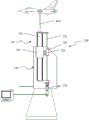
FIG. 1 is a schematic diagram of the overall structure of a low-speed wind tunnel virtual flight test device;
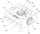
FIG. 2 is a schematic view of a corner head according to a first view of the present application;
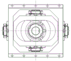
FIG. 3 is a schematic view of a second view of the corner head of the present application;
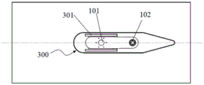
fig. 4 is a schematic cross-sectional view of a rectifier of the present application.
Marked in the figure as: 100-lifting components, 101-guide rails, 102-screw rods, 103-motors, 200-weighing components, 201-weighing sensors, 202-nuts, 300-rectifying frames, 301-bases, 401-mandrels, 402-second rotating shafts, 403-third rotating shafts, 501-first bearings, 502-second bearings, 503-third bearings, 601-inner frames, 602-middle frames, 603-outer frames, 701-first limiting structures, 702-second limiting structures and 800-supporting rods.
Detailed Description
The following description of the specific embodiments of the present invention will be given with reference to the accompanying drawings, so as to further understand the concept of the present invention, the technical problems to be solved, the technical features constituting the technical solutions, and the technical effects to be brought about. However, the description of these embodiments is illustrative, and does not constitute a specific limitation on the present invention.
Firstly, this application adopts balancing weight, act as go-between and fixed pulley balance model lift weight in solving traditional scheme, exists great error, hardly realizes the technical problem of model free heave in the plumb direction, and this application is realized like this:
the application provides a low-speed wind tunnel virtual flight test device, which comprises a lifting assembly 100, a weighing assembly 200, a rectifying frame 300 and an absolute position encoder. The lifting assembly 100 comprises a motor 103, and the motor 103 drives the lifting assembly 100 to lift up and down integrally. The load cell 201 in the weighing module 200 measures the load and change in the vertical direction of the lifting module 100 and other structures such as a model mounted on the lifting module 100. The amount of change in the output of the absolute position encoder can determine the direction of movement of the lift assembly 100. And a moment control mode is adopted for the motor 103 by combining the output quantity variation of the weighing sensor 201 and the movement direction judged by the absolute position encoder, so that a model arranged on the low-speed wind tunnel virtual flight test device is in a dynamic stress balance state in the vertical direction.
Specifically, as shown in fig. 1 and 4:
the present application includes a lift assembly 100, a weighing assembly 200, and a rectifier frame 300. The lifting assembly 100 includes a guide rail 101, a screw 102, and a motor 103. The load cell 200 includes a load cell 201 and a nut 202. The weighing sensor 201 is fixedly connected to the rectifying frame 300, the nut 202 is fixedly connected to the weighing sensor 201, the guide rail 101 is in sliding fit with the rectifying frame 300, and the screw rod 102 and the nut 202 form a screw rod 102 nut 202 pair. The output shaft of the motor 103 is in transmission connection with the screw rod 102, and the screw rod 102 rotates under the action of the motor 103 to drive the lifting assembly 100 to integrally lift or descend along the plumb direction. The present application also includes an absolute position encoder associated with the motor 103.
It should be understood by those skilled in the art that the nut 202 is provided with an internal thread that cooperates with the screw 102, and has various shapes, and the shape is not limited in the present application, and a user may adapt to design according to factors such as installation environment, connection cooperation, and the like. The lifting assembly 100 in this application includes a guide rail 101, where the guide rail 101 is slidably engaged with the rectifying frame 300 to limit the movement direction of the lifting assembly 100. Screw rod 102 and nut 202 are connected to form screw-nut pair, nut 202 and weighing sensor 201 fixed connection, weighing sensor 201 and rectification frame 300 fixed connection, motor 103 drive screw rod 102 rotate, because nut 202 is fixed can realize screw rod 102 up-and-down motion, and then realize lifting assembly 100 wholly and do ascending or descending motion in the plumb direction.
Further, a base 301 is disposed in the rectifying frame 300, the base 301 is fixedly connected with the rectifying frame 300, and the guide rail 101 is slidably matched with the base 301, that is, the purpose of slidably matching the guide rail 101 with the rectifying frame 300 is achieved. It should be understood that the specific structure, dimensions, etc. of the base 301 are numerous and various, and the specific structure of the base 301 is not limited in this application. In this embodiment, a through hole penetrating in the vertical direction is formed in the base 301, the axis of the guide rail 101 is parallel to the vertical direction and is in sliding fit with the through hole, and the outer side of the base 301 is fixedly connected with the rectifying frame 300, which may be a bolt connection, a clamping connection, or the like.
When the rectifying frame 300 of the present application is provided with the base 301, after the base 301 slides along the guide rail 101, the weighing sensor 201 may be further fixedly connected to the base 301, so as to achieve the fixed connection between the weighing sensor 201 and the rectifying frame 300.
Referring to fig. 4, in the embodiment of the present application, the cross-sectional shape of the rectifying frame is a symmetrical airfoil.
Referring to fig. 1, a load cell 201 of the present application measures loads and changes in the vertical direction of a lifting assembly 100 and other structures mounted on the lifting assembly 100, such as a strut 800, a model, a corner head, etc. For which component of the load cell 201 the nut 202 is specifically mounted on, which component of the load cell 201 is fixedly connected to the rectifying frame 300, etc., those skilled in the art will easily recognize the range of measurement to be performed by the load cell 201, and therefore, the description thereof will not be repeated here.
The output shaft of the motor 103 is in transmission connection with the screw rod 102, and the motor 103 drives the screw rod 102 to rotate so as to drive the lifting assembly 100 to move up and down. It is easy to understand that the motor 103 can be horizontally mounted or vertically mounted, and the motor 103 can drive the screw rod 102 to rotate when being matched with a transmission structure such as a spur gear, a bevel gear, a coupler and the like. Therefore, the specific transmission connection structure between the output shaft of the motor 103 and the screw 102 is not limited in this application. However, as shown in fig. 1, in the present application, preferably, the motor 103 is installed vertically, the output shaft of the motor 103 is coaxially disposed with the screw 102, the output shaft of the motor 103 is fixedly connected with the screw 102 by a coupling, and the housing of the motor 103 is fixedly connected with a connecting piece on the lifting assembly 100 for connecting the screw 102 with the guide rail 101. By the design, the transmission structure can be reduced, the structure is simplified, the force output by the motor 103 directly acts on the screw rod 102, the energy loss caused by multistage transmission is avoided, and the transmission effect is better.
In the application, the motor 103 plays a vital role in adjusting dynamic stress balance in the vertical direction, and the acting force of the motor is opposite to the resultant force direction of the gravity and friction resistance of the model, the lifting assembly and the corner head by adjusting the output moment of the motor, so that the variation of the output quantity of the absolute position encoder is zero, and the model is dynamically stressed and balanced in the vertical direction. One preferred motor 103 that can achieve the above functions is an ac servo motor.
In the prior art, most motors 103 are provided with an absolute position encoder, and when the motors 103 are provided with the absolute position encoder, the absolute position encoder does not need to be separately arranged. If the motor 103 is used without an absolute position encoder, it is necessary to set the absolute position encoder by the user himself. The mounting manner, mounting position, etc. of the absolute position encoder are well known to those skilled in the art, and will not be described in detail herein.
The guide rail 101 is slidably connected with the rectifying frame 300, the screw rod 102 and the nut 202 form a screw-nut pair, preferably, the guide rail 101 is a ball linear guide rail, and the screw rod 102 is a ball screw rod, so that friction resistance in the transmission process is reduced.
Further, in the traditional scheme, after the technical problem that the weight is lifted by adopting the balancing weight, the stay wire and the fixed pulley to balance the model, and the free lifting of the model in the vertical direction is difficult to realize is solved, when the corner head adopts the Hooke hinge on the basis, the two-axis gesture motion of the model can be generally realized, and even if the three-axis gesture motion of the model can be realized, the degree of freedom of the structure cannot be in one-to-one correspondence with the three-axis gesture rotation of the model, and the three-axis gesture rotation of one or two models can not be independently locked or independently released; when the corner head adopts a spherical hinge structure, the three-axis gesture rotation of the model cannot be controlled independently. The application is realized in such a way that:
the utility model provides a virtual flying test device of low-speed wind tunnel still includes setting up in lifting unit 100 top, with lifting unit 100 fixed connection's dabber 401, and dabber 401's axial lead is parallel with the plumb direction, dabber 401 upper end is provided with the inner frame 601 of rotating the connection through first bearing 501, inner frame 601 can do yaw direction rotation around dabber 401's axial lead.
Specifically, the connection between the mandrel 401 and the lifting assembly 100 is various, and the mandrel is fastened by bolts, welded, or the like. Typically, a supporting rod 800 is disposed between the lifting assembly 100 and the mandrel 401, as shown in fig. 1, the lower end of the supporting rod 800 is fixedly connected with the lifting assembly 100, the upper end of the supporting rod 800 is fixedly connected with the mandrel 401, and the supporting rod 800 is generally conical. In the present application, the support bar 800 may or may not be provided, and the user may decide to use the support bar 800.
The spindle 401 is a rotation shaft for rotating the inner frame 601, and as shown in fig. 2 and 3, the inner frame 601 and the spindle 401 rotate through the first bearing 501, and the inner frame 601 rotates around the axis of the spindle 401 to realize yaw rotation. The axis of the spindle 401 is parallel to the vertical direction to ensure that the rotation of the inner frame 601 around the spindle 401, that is, the rotation in the yaw angle direction.
Further, in the present application, the inner frame 601 is provided with a second rotation shaft 402, an axis of the second rotation shaft 402 is horizontally disposed, a middle frame 602 is disposed outside the inner frame 601, the middle frame 602 is rotatably connected with the second rotation shaft 402 through a second bearing 502, and the middle frame 602 can rotate around an axis of the second rotation shaft 402 in a pitching direction.
Still further, a third rotating shaft 403 is disposed on the middle frame 602, an axis of the third rotating shaft 403 is perpendicular to an axis of the second rotating shaft 402, axes of the mandrel 401, the second rotating shaft 402 and the third rotating shaft 403 intersect in a space, an outer frame 603 is disposed outside the middle frame 602, the outer frame 603 is rotatably connected with the third rotating shaft 403 through a third bearing 503, the outer frame 603 can rotate around an axis of the third rotating shaft 403 in a rolling direction, can rotate around an axis of the second rotating shaft 402 in a pitching direction, and can rotate around an axis of the mandrel 401 in a yaw direction.
The low-speed wind tunnel virtual flight test device provided by the application is characterized in that a model is installed on the outer frame 603. The model is fixedly installed on the outer frame 603, and when the longitudinal axis of the machine body of the model is parallel to the axis of the third rotating shaft 403 and the transverse axis of the machine body is parallel to the axis of the second rotating shaft 402, the model can swing freely in the yaw direction, the pitch direction and the roll direction. The three swinging directions are mutually independent and do not interfere with each other, so that the multi-direction simultaneous swinging can be realized, and the unidirectional swinging can also be realized. The technical problem that the traditional Hooke hinge model can only realize two-axis gesture movement, and even the three-axis gesture movement of the model can not realize one-to-one correspondence of the degree of freedom of the structure of the model to the gesture rotation of the model is solved. The technical problem that the three-axis attitude angle rotation of the model cannot be controlled independently by adopting a spherical hinge in the prior art is solved.
As shown in fig. 2, in the embodiment of the present application, the inner frame 601 has a cylindrical shape, in which a first shaft hole is provided, and the shaft hole is rotatably connected with the spindle 401 through a first bearing 501. Two coaxial second rotating shafts 402 are arranged on the outer side face of the inner frame 601, the axes of the second rotating shafts 402 are horizontally arranged, the middle frame 602 is in a shape like a Chinese character 'kou', the outer side of the inner frame 601 is sleeved with the middle frame 602, two coaxial second shaft holes are formed in the outer side face of the middle frame 602, and the second shaft holes are rotatably connected with the second rotating shafts 402 through second bearings 502. The outer frame 603 is also shaped like a Chinese character 'kou', and is sleeved on the outer side of the middle frame 602, two coaxial third rotating shafts 403 are arranged on the outer side surface of the middle frame 602, the axial lead of each third rotating shaft 403 is perpendicular to the axial lead of each second rotating shaft 402, the axial leads of the mandrel 401, the second rotating shafts 402 and the third rotating shafts 403 intersect at one point in space, and two coaxial third shaft holes are formed in the outer frame 603 and are rotationally connected with the third rotating shafts 403 through third bearings 503.
In the present application, the inner frame 601 is not limited to a cylindrical shape as shown in fig. 2 and 3, it may be other shapes, the outer shapes of the middle frame 602 and the outer frame 603 are not limited to a mouth shape as shown in fig. 2 and 3, it may be a circular shape, an oval shape, etc., and is not limited in the present application.
Further, in order to limit the swing angle in each direction, the first limiting structures 701 are disposed on the mandrel 401, the second rotating shaft 402 and the third rotating shaft 403, the second limiting structures 702 are disposed on the inner frame 601, the middle frame 602 and the outer frame 603, and the first limiting structures 701 are disposed on the rotating paths of the second limiting structures 702 to limit the rotating ranges of the inner frame 601, the middle frame 602 and the outer frame 603. The first and second stop structures 701, 701 are in a wide variety of forms.
In the specific embodiment of the present application, as shown in fig. 2 and 3, the first limiting structure 701 is a positioning rod fixed on the mandrel 401, the second rotating shaft 402, and the third rotating shaft 403; the second limiting structure 702 is two stoppers arranged on each frame, and the positioning rod is located between the two stoppers, so that the rotation ranges of the inner frame 601, the middle frame 602 and the outer frame 603 can be limited, that is, the limitation of the rotation angles of the model in three gesture directions is realized. In this embodiment, the dog is detachably connected on inner frame 601, middle frame 602 and outer frame 603, that is to say that two dogs on the same frame are adjustable in mutual interval, and then can realize the regulation of rotation scope, can even with two dog chucking locating lever, reaches the effect of locking the locating lever, has realized locking corresponding direction pivoted effect promptly. According to the structure disclosed by the embodiment of the application, the rotation in one or two directions can be independently locked or independently released, and the technical problem that the Hooke hinge cannot be independently locked or the model attitude rotation of one or two directions can be independently released can be solved.
In addition to the structure described in this embodiment, the swing angle in each direction can be limited, and the following structures can be also implemented: 1. the first limiting structure 701 is two stoppers respectively arranged on the mandrel 401, the second rotating shaft 402 and the third rotating shaft 403, the second limiting structure 702 is a positioning rod arranged on the inner frame 601, the middle frame 602 and the outer frame 603, and the positioning rod is positioned between the two stoppers; 2. the first limiting structure 701 is a positioning rod fixed on the mandrel 401, the second rotating shaft 402 and the third rotating shaft 403, the second limiting structure 702 is a limiting groove formed on the inner frame 601, the middle frame 602 and the outer frame 603, and the positioning rod is positioned in the limiting groove; 3. the first limiting structure 701 is a limiting protrusion arranged on the side surfaces of the mandrel 401, the second rotating shaft 402 and the third rotating shaft 403, the second limiting structure 702 is a limiting groove arranged on the side surface of each frame shaft hole, and the limiting protrusion is positioned in the limiting groove.
Further, the present application further includes a supporting rod 800, where the lower portion of the supporting rod 800 is fixedly connected to the lifting assembly 100, and the upper portion of the supporting rod is fixedly connected to the mandrel 401, as shown in fig. 1.
The spindle 401, the second rotation shaft 402, the third rotation shaft 403, the inner frame 601, the middle frame 602, the outer frame 603, the first limiting structure 701, the second limiting structure 702, and the like together constitute a corner head. In the wind tunnel experiment, the model is fixedly installed on the corner head, specifically, for the application, the model is installed on the outer frame 603, so that a connecting structure which is in matched connection with the model is preferably arranged on the outer frame 603. These structures can be buckles, threaded holes, etc., and are not limited in this application, and the user can set up by himself according to the test requirements, connection strength, etc.
Finally, for ease of understanding, the present application describes the stress and method of use of the structure of the present application, taking the structure shown in fig. 1 as an example.
Firstly, the motor 103 controls the screw rod 102 to rotate so as to realize the up-and-down lifting of the model.
Before the blowing experiment, if the influence of the friction resistance on the transmission process is not considered, when the structure shown in fig. 1 is stressed and balanced in the vertical direction, the acting force of the base 301 on the lifting assembly 100 is the sum of the gravity of the lifting assembly 100, the model, the support rod 800 and the corner head.
In the blowing experiment, if the influence of friction resistance on the transmission process is not considered, when the structure shown in fig. 1 is stressed and balanced in the vertical direction, the acting force of the base 301 on the lifting assembly 100 is the vector sum of the gravity of the lifting assembly 100, the model, the corner head and the support rod 800 and the aerodynamic lift force exerted on the model.
Before the blowing experiment, if the influence of the friction resistance on the transmission process is considered, when the structure shown in fig. 1 is stressed and balanced in the vertical direction, the acting force of the base 301 on the lifting assembly 100 is the vector sum of the gravity and the friction resistance of the lifting assembly 100, the model, the corner head and the support rod 800. The frictional resistance is equal to half the output of the load cell 201 before and after the model heave direction is changed.
After the blowing experiment, if the influence of the friction resistance on the transmission process is considered, when the model moves up and down under the action of pneumatic lifting force, the output quantity of the absolute position encoder matched with the motor 103 changes, and the lifting movement direction of the model can be judged according to the sign of the output quantity, so that the direction of the friction resistance can be judged. At this time, the weighing sensor 201 can measure the load and the change of the lifting assembly 100, the model, the corner head and the strut 800 in the vertical direction, and the acting force of the lifting assembly, the lifting assembly and the corner head are opposite to the resultant force direction of the gravity and the friction resistance of the model by adjusting the output moment of the motor, so that the change amount of the output quantity of the absolute position encoder matched with the motor 103 is zero, and the model can be in a dynamic stress balance state in the vertical direction, and the influence condition of the aerodynamic lift force of the model on the model state can be obtained.
Finally, it should be noted that: the above embodiments are only for illustrating the technical solution of the present invention, and are not limiting; while the invention has been described in detail with reference to the foregoing embodiments, it will be appreciated by those skilled in the art that variations may be made in the techniques described in the foregoing embodiments, or equivalents may be substituted for elements thereof; such modifications and substitutions do not depart from the spirit and scope of the technical solutions of the embodiments of the present invention.
Claims (10)
1. The utility model provides a virtual flight test device in low-speed wind tunnel which characterized in that:
comprises a lifting assembly (100), a weighing assembly (200) and a rectifying frame (300);
the lifting assembly (100) comprises a guide rail (101), a screw rod (102) and a motor (103),
the weighing assembly (200) comprises a weighing sensor (201) and a nut (202), wherein the weighing sensor (201) is fixedly connected to the rectifier frame (300), the nut (202) is fixedly connected to the weighing sensor (201),
the guide rail (101) is in sliding fit with the rectifying frame (300), the screw rod (102) and the nut (202) form a screw rod nut pair,
an output shaft of the motor (103) is in transmission connection with the screw rod (102), and the screw rod (102) rotates under the action of the motor (103) to drive the lifting assembly (100) to ascend or descend along the vertical direction;
also comprises an absolute position encoder which is matched with the motor (103) and is arranged on the motor (103).
2. The low-speed wind tunnel virtual flight test apparatus of claim 1, wherein: the rectifier frame (300) is internally provided with a base (301), the guide rail (101) is in sliding fit with the base (301), and the weighing sensor (201) is fixedly connected to the base (301).
3. The low-speed wind tunnel virtual flight test apparatus of claim 1, wherein: the motor (103) is an alternating current servo motor, and an output shaft of the motor (103) and the screw rod (102) are coaxially arranged and fixedly connected.
4. The low-speed wind tunnel virtual flight test apparatus of claim 1, wherein: the guide rail (101) is a ball linear guide rail, and the screw rod (102) is a ball screw rod.
5. A low speed wind tunnel virtual flight test apparatus according to any one of claims 1 to 4, wherein: the automatic lifting device is characterized by further comprising a mandrel (401) which is arranged above the lifting assembly (100) and fixedly connected with the lifting assembly (100), wherein the axis of the mandrel (401) is parallel to the vertical direction, an inner frame (601) which is rotationally connected through a first bearing (501) is arranged on the mandrel (401), and the inner frame (601) can rotate in the yaw direction around the axis of the mandrel (401).
6. The low-speed wind tunnel virtual flight test apparatus of claim 5, wherein: the inner frame (601) is provided with a second rotating shaft (402), the axis of the second rotating shaft (402) is horizontal, the outer side of the inner frame (601) is provided with a middle frame (602), the middle frame (602) is rotationally connected with the second rotating shaft (402) through a second bearing (502), and the middle frame (602) can rotate in the pitching direction around the axis of the second rotating shaft (402).
7. The low-speed wind tunnel virtual flight test apparatus of claim 6, wherein: the middle frame (602) is provided with a third rotating shaft (403), the axial lead of the third rotating shaft (403) is perpendicular to the axial lead of the second rotating shaft (402), the axial leads of the mandrel (401), the second rotating shaft (402) and the third rotating shaft (403) are intersected in a point in space, an outer frame (603) is arranged outside the middle frame (602), the outer frame (603) is rotationally connected with the third rotating shaft (403) through a third bearing (503), and the outer frame (603) can rotate around the axial lead of the third rotating shaft (403) in a rolling direction, can rotate around the axial lead of the second rotating shaft (402) in a pitching direction and can rotate around the axial lead of the mandrel (401) in a yawing direction.
8. The low-speed wind tunnel virtual flight test apparatus of claim 7, wherein: the novel rotary shaft is characterized in that a first limiting structure (701) is fixedly arranged on each of the mandrel (401), the second rotating shaft (402) and the third rotating shaft (403), a second limiting structure (702) is fixedly arranged on each of the inner frame (601), the middle frame (602) and the outer frame (603), and the first limiting structure (701) is located on a rotating path of the second limiting structure (702) to limit the rotating range of the inner frame (601), the middle frame (602) and the outer frame (603).
9. The low-speed wind tunnel virtual flight test apparatus of claim 8, wherein: the first limiting structure (701) is a positioning rod arranged on each shaft, the second limiting structure (702) is two stop blocks arranged on each frame, and the positioning rod is positioned between the two stop blocks.
10. The low-speed wind tunnel virtual flight test apparatus of claim 7, wherein: the lifting device further comprises a supporting rod (800), wherein the lower part of the supporting rod (800) is fixedly connected with the lifting assembly (100), and the upper part of the supporting rod (800) is fixedly connected with the mandrel (401).
Priority Applications (1)
| Application Number | Priority Date | Filing Date | Title |
|---|---|---|---|
| CN202310510549.4A CN116242575B (en) | 2023-05-08 | 2023-05-08 | Virtual flight test device of low-speed wind tunnel |
Applications Claiming Priority (1)
| Application Number | Priority Date | Filing Date | Title |
|---|---|---|---|
| CN202310510549.4A CN116242575B (en) | 2023-05-08 | 2023-05-08 | Virtual flight test device of low-speed wind tunnel |
Publications (2)
| Publication Number | Publication Date |
|---|---|
| CN116242575A true CN116242575A (en) | 2023-06-09 |
| CN116242575B CN116242575B (en) | 2023-07-21 |
Family
ID=86628110
Family Applications (1)
| Application Number | Title | Priority Date | Filing Date |
|---|---|---|---|
| CN202310510549.4A Active CN116242575B (en) | 2023-05-08 | 2023-05-08 | Virtual flight test device of low-speed wind tunnel |
Country Status (1)
| Country | Link |
|---|---|
| CN (1) | CN116242575B (en) |
Citations (17)
| Publication number | Priority date | Publication date | Assignee | Title |
|---|---|---|---|---|
| JPH08313388A (en) * | 1995-05-18 | 1996-11-29 | Mitsubishi Heavy Ind Ltd | Wind tunnel test device |
| CN101532895A (en) * | 2009-03-31 | 2009-09-16 | 清华大学 | Tension scale two and a half shaft force decomposer |
| CN101936806A (en) * | 2010-07-21 | 2011-01-05 | 北京航空航天大学 | Measurement device for aerodynamic force of attitude control motor plume on large-sized solar cell wing |
| US20130338982A1 (en) * | 2012-06-13 | 2013-12-19 | Robert B. Schwab | Engine Vibration And Engine Trim Balance Test System, Apparatus And Method |
| CN203811349U (en) * | 2014-03-31 | 2014-09-03 | 南京航空航天大学 | Rotor dynamic test device |
| CN206450397U (en) * | 2016-12-29 | 2017-08-29 | 中国航天空气动力技术研究院 | A kind of big attack angle mechanism of sub- transonic and supersonic wind tunnel with translation functions |
| CN108593169A (en) * | 2018-04-19 | 2018-09-28 | 哈尔滨工业大学 | Rotary wind type Mars unmanned plane single rotor system gas dynamic characteristic test device and torsion-testing method and lift test method |
| DE102017127142A1 (en) * | 2017-11-17 | 2019-05-23 | Rolls-Royce Deutschland Ltd & Co Kg | An aircraft monitoring system and method for collecting aircraft maintenance data |
| CN110207943A (en) * | 2019-06-26 | 2019-09-06 | 中国航天空气动力技术研究院 | Hypersonic wind tunnel virtual flight pilot system and test method |
| CN110887635A (en) * | 2019-12-04 | 2020-03-17 | 中国航空工业集团公司哈尔滨空气动力研究所 | Aircraft longitudinal short-period simulation test device based on horizontal wind tunnel |
| CN111284730A (en) * | 2020-03-24 | 2020-06-16 | 北京理工大学珠海学院 | Rotor craft comprehensive test experiment simulation platform and test method |
| CN113252285A (en) * | 2021-07-15 | 2021-08-13 | 中国空气动力研究与发展中心低速空气动力研究所 | Vertical wind tunnel model pitching-rolling test device and use method |
| CN114310734A (en) * | 2022-03-14 | 2022-04-12 | 中国空气动力研究与发展中心低速空气动力研究所 | Airplane model sinking and floating supporting device and four-degree-of-freedom supporting device |
| CN114414191A (en) * | 2021-12-28 | 2022-04-29 | 中国航天空气动力技术研究院 | Pneumatic test device for control surface model |
| CN216621681U (en) * | 2021-12-24 | 2022-05-27 | 西安现代控制技术研究所 | Novel dynamic derivative elastic hinge calibration device |
| CN115077846A (en) * | 2022-07-28 | 2022-09-20 | 中国空气动力研究与发展中心高速空气动力研究所 | Large wind tunnel ground preparation platform |
| CN115183983A (en) * | 2022-09-13 | 2022-10-14 | 中国航空工业集团公司沈阳空气动力研究所 | Control surface hinge moment balance verification loading device |
-
2023
- 2023-05-08 CN CN202310510549.4A patent/CN116242575B/en active Active
Patent Citations (17)
| Publication number | Priority date | Publication date | Assignee | Title |
|---|---|---|---|---|
| JPH08313388A (en) * | 1995-05-18 | 1996-11-29 | Mitsubishi Heavy Ind Ltd | Wind tunnel test device |
| CN101532895A (en) * | 2009-03-31 | 2009-09-16 | 清华大学 | Tension scale two and a half shaft force decomposer |
| CN101936806A (en) * | 2010-07-21 | 2011-01-05 | 北京航空航天大学 | Measurement device for aerodynamic force of attitude control motor plume on large-sized solar cell wing |
| US20130338982A1 (en) * | 2012-06-13 | 2013-12-19 | Robert B. Schwab | Engine Vibration And Engine Trim Balance Test System, Apparatus And Method |
| CN203811349U (en) * | 2014-03-31 | 2014-09-03 | 南京航空航天大学 | Rotor dynamic test device |
| CN206450397U (en) * | 2016-12-29 | 2017-08-29 | 中国航天空气动力技术研究院 | A kind of big attack angle mechanism of sub- transonic and supersonic wind tunnel with translation functions |
| DE102017127142A1 (en) * | 2017-11-17 | 2019-05-23 | Rolls-Royce Deutschland Ltd & Co Kg | An aircraft monitoring system and method for collecting aircraft maintenance data |
| CN108593169A (en) * | 2018-04-19 | 2018-09-28 | 哈尔滨工业大学 | Rotary wind type Mars unmanned plane single rotor system gas dynamic characteristic test device and torsion-testing method and lift test method |
| CN110207943A (en) * | 2019-06-26 | 2019-09-06 | 中国航天空气动力技术研究院 | Hypersonic wind tunnel virtual flight pilot system and test method |
| CN110887635A (en) * | 2019-12-04 | 2020-03-17 | 中国航空工业集团公司哈尔滨空气动力研究所 | Aircraft longitudinal short-period simulation test device based on horizontal wind tunnel |
| CN111284730A (en) * | 2020-03-24 | 2020-06-16 | 北京理工大学珠海学院 | Rotor craft comprehensive test experiment simulation platform and test method |
| CN113252285A (en) * | 2021-07-15 | 2021-08-13 | 中国空气动力研究与发展中心低速空气动力研究所 | Vertical wind tunnel model pitching-rolling test device and use method |
| CN216621681U (en) * | 2021-12-24 | 2022-05-27 | 西安现代控制技术研究所 | Novel dynamic derivative elastic hinge calibration device |
| CN114414191A (en) * | 2021-12-28 | 2022-04-29 | 中国航天空气动力技术研究院 | Pneumatic test device for control surface model |
| CN114310734A (en) * | 2022-03-14 | 2022-04-12 | 中国空气动力研究与发展中心低速空气动力研究所 | Airplane model sinking and floating supporting device and four-degree-of-freedom supporting device |
| CN115077846A (en) * | 2022-07-28 | 2022-09-20 | 中国空气动力研究与发展中心高速空气动力研究所 | Large wind tunnel ground preparation platform |
| CN115183983A (en) * | 2022-09-13 | 2022-10-14 | 中国航空工业集团公司沈阳空气动力研究所 | Control surface hinge moment balance verification loading device |
Non-Patent Citations (3)
| Title |
|---|
| WANG TIANHAO: ""Definition Measurement Unit with Flexure Hinges for a Wind Tunnel Balance"", 《PROCEEDINGS OF THE 2010 IEEE INTERNATIONAL CONFERENCE ON INFORMATION AND AUTOMATION》, pages 1457 - 1462 * |
| 张海酉: "" FL-14风洞两自由度动态试验装置优化研究"", 《第五届非定常空气动力学学术会议论文集》, pages 21 - 25 * |
| 聂博文: ""倾转四旋翼无人机风洞虚拟飞行初步验证"", 《中国力学大会论文集(CCTAM 2019)》, pages 3137 - 3146 * |
Also Published As
| Publication number | Publication date |
|---|---|
| CN116242575B (en) | 2023-07-21 |
Similar Documents
| Publication | Publication Date | Title |
|---|---|---|
| CN104787363B (en) | A kind of satellite ground microgravity dynamic load simulation mechanism | |
| CN105547676B (en) | A kind of arm-type rotor model.test system of multifunctional rotary | |
| CN104132795B (en) | A kind of model cable support system realizing wind-tunnel virtual flight | |
| CN205642791U (en) | Wind -tunnel is with toper motion simulation device of rotatory guided missile | |
| CN109018430B (en) | Rotorcraft blade performance test bench | |
| CN105151280B (en) | Aircraft empennage regulation mechanism with pitching and yawing completely decoupled | |
| CN110836760B (en) | Ship attitude dynamic simulation system for wind tunnel test and working method thereof | |
| CN211347313U (en) | Two-degree-of-freedom dynamic test supporting device for open wind tunnel | |
| CN107757955A (en) | Multi-joint space mechanism gravity unloading device | |
| CN108344553B (en) | Wind tunnel test model parallel mechanism supporting device for aircraft formation flight | |
| CN106240843B (en) | Multi-rotor unmanned aerial vehicle structured testing device and method based on reducing rack | |
| CN2861012Y (en) | Research exploitation platform for flapping-wing flight robot | |
| CN110686855B (en) | High-speed wind tunnel translational vibration dynamic derivative test device | |
| CN111855216A (en) | Test piece rotary driving device for centrifugal overload test of solid rocket engine | |
| CN108454882A (en) | A kind of driving of rudder face and rudder face angle measuring mechanism | |
| CN102717897A (en) | Aerodynamic loading system and loading method for undercarriage self-control spring-damping system | |
| CN107036781A (en) | Low resistance Three Degree Of Freedom support meanss based on virtual flight test model | |
| CN106078688B (en) | A kind of heavy duty self-balancing 3-freedom parallel mechanism | |
| CN112067245A (en) | High-speed wind tunnel translational vibration dynamic derivative test device and test method | |
| CN106005458A (en) | Self-stabilizing platform for high-attitude shooting of unmanned aerial vehicle | |
| CN116242575B (en) | Virtual flight test device of low-speed wind tunnel | |
| CN114923656A (en) | Rope supporting system for full-aircraft flutter wind tunnel test | |
| CN107860545A (en) | The six degree of freedom system of large-scale transonic wind tunnel big load model captive trajectory testing | |
| CN208070050U (en) | A kind of driving of rudder face and rudder face angle measuring mechanism | |
| CN111044221B (en) | Three-dimensional inertia testboard adjusting device of unmanned aerial vehicle |
Legal Events
| Date | Code | Title | Description |
|---|---|---|---|
| PB01 | Publication | ||
| PB01 | Publication | ||
| SE01 | Entry into force of request for substantive examination | ||
| SE01 | Entry into force of request for substantive examination | ||
| GR01 | Patent grant | ||
| GR01 | Patent grant |