CN116183840A - Environment monitoring system for intelligent environmental protection engineering - Google Patents
Environment monitoring system for intelligent environmental protection engineering Download PDFInfo
- Publication number
- CN116183840A CN116183840A CN202310484907.9A CN202310484907A CN116183840A CN 116183840 A CN116183840 A CN 116183840A CN 202310484907 A CN202310484907 A CN 202310484907A CN 116183840 A CN116183840 A CN 116183840A
- Authority
- CN
- China
- Prior art keywords
- shaft
- rod
- gear
- rotating shaft
- driving
- Prior art date
- Legal status (The legal status is an assumption and is not a legal conclusion. Google has not performed a legal analysis and makes no representation as to the accuracy of the status listed.)
- Granted
Links
Images


Classifications
-
- F—MECHANICAL ENGINEERING; LIGHTING; HEATING; WEAPONS; BLASTING
- F03—MACHINES OR ENGINES FOR LIQUIDS; WIND, SPRING, OR WEIGHT MOTORS; PRODUCING MECHANICAL POWER OR A REACTIVE PROPULSIVE THRUST, NOT OTHERWISE PROVIDED FOR
- F03D—WIND MOTORS
- F03D9/00—Adaptations of wind motors for special use; Combinations of wind motors with apparatus driven thereby; Wind motors specially adapted for installation in particular locations
- F03D9/10—Combinations of wind motors with apparatus storing energy
- F03D9/11—Combinations of wind motors with apparatus storing energy storing electrical energy
-
- F—MECHANICAL ENGINEERING; LIGHTING; HEATING; WEAPONS; BLASTING
- F03—MACHINES OR ENGINES FOR LIQUIDS; WIND, SPRING, OR WEIGHT MOTORS; PRODUCING MECHANICAL POWER OR A REACTIVE PROPULSIVE THRUST, NOT OTHERWISE PROVIDED FOR
- F03D—WIND MOTORS
- F03D15/00—Transmission of mechanical power
-
- G—PHYSICS
- G01—MEASURING; TESTING
- G01N—INVESTIGATING OR ANALYSING MATERIALS BY DETERMINING THEIR CHEMICAL OR PHYSICAL PROPERTIES
- G01N1/00—Sampling; Preparing specimens for investigation
- G01N1/02—Devices for withdrawing samples
- G01N1/22—Devices for withdrawing samples in the gaseous state
- G01N1/2247—Sampling from a flowing stream of gas
- G01N1/2252—Sampling from a flowing stream of gas in a vehicle exhaust
-
- G—PHYSICS
- G01—MEASURING; TESTING
- G01N—INVESTIGATING OR ANALYSING MATERIALS BY DETERMINING THEIR CHEMICAL OR PHYSICAL PROPERTIES
- G01N1/00—Sampling; Preparing specimens for investigation
- G01N1/02—Devices for withdrawing samples
- G01N1/22—Devices for withdrawing samples in the gaseous state
- G01N1/24—Suction devices
-
- G—PHYSICS
- G01—MEASURING; TESTING
- G01N—INVESTIGATING OR ANALYSING MATERIALS BY DETERMINING THEIR CHEMICAL OR PHYSICAL PROPERTIES
- G01N33/00—Investigating or analysing materials by specific methods not covered by groups G01N1/00 - G01N31/00
- G01N33/0004—Gaseous mixtures, e.g. polluted air
Abstract
The invention provides an environment monitoring system for intelligent environmental protection engineering, which relates to the technical field of measuring equipment, and comprises an air collection and detection module, wherein the air collection and detection module comprises: a gas collecting tube; an air inlet pipe; a CO concentration sensor; the output end of the driving motor is connected with a connecting shaft, the connecting shaft is connected with a rotating shaft through a unidirectional transmission mechanism, and the rotating shaft is provided with air suction fan blades; a storage battery; the input end of the generator is connected with the rotating shaft through a transmission shaft, a first gear, a movable shaft and a second gear, the transmission shaft is in transmission connection with the rotating shaft, the first gear is arranged on the transmission shaft, the movable shaft is spliced with the input end of the generator and can drive the input end of the generator to rotate, and the second gear is arranged on the movable shaft; detecting a driving mechanism; under strong wind weather, the rotating speed of the rotating shaft can be higher than that of the connecting shaft, and at the moment, the detection driving mechanism can drive the movable shaft to move so that the second gear is meshed with the first gear, and accordingly the input end of the generator is driven to rotate to generate electricity.
Description
Technical Field
The invention relates to the technical field of measuring equipment, in particular to an environment monitoring system for intelligent environmental protection engineering.
Background
The intelligent environment protection is an extension and expansion of a digital environment protection concept, an inductor and equipment are embedded into various environment monitoring objects by means of the technology of the Internet of things, the Internet of things in the environment protection field is integrated by a supercomputer and cloud computing, integration of a human society and an environment business system can be realized, and the intelligent of environment management and decision making is realized in a finer and dynamic mode.
The type with the largest quantity of the existing automobiles is a fuel oil automobile, and the problem of pollutant emission of automobile exhaust is still serious. According to research and analysis, the harmful components in the tail gas discharged by the automobile reach 260 or more, such as harmful gases with great harm to human bodies, such as carbon monoxide and the like.
Automobile exhaust emission has become an environmental pollution problem which is more and more concerned by the public of society, and the application of the concept of intelligent environmental protection to monitor automobile exhaust emission pollutants in the ambient air is beneficial to the control of the automobile exhaust emission pollutants in the ambient air.
Disclosure of Invention
In view of the above, the invention provides an environment monitoring system for intelligent environmental engineering, which can monitor the pollutant discharged by automobile exhaust in the ambient air.
In order to achieve the above purpose, the present invention provides the following technical solutions:
the invention provides an environment monitoring system for intelligent environmental protection engineering, which mainly comprises: the system comprises an air collection and detection module, a data acquisition and transmission module, a central control processing module and a warning module; the air collection and detection module comprises:
a gas collecting tube, the inside of which is provided with a flow passage for air to pass through;
the air inlet pipes are communicated with the flow channels and are distributed along the circumferential direction of the gas collecting pipe;
the CO concentration sensor is arranged in the flow channel;
the driving motor is arranged in the flow channel, the output end of the driving motor is in transmission connection with a connecting shaft, the connecting shaft is connected with a rotating shaft through a unidirectional transmission mechanism, and the rotating shaft is provided with air suction fan blades;
the storage battery is used for supplying power to the CO concentration sensor;
the output end of the generator is electrically connected with the input end of the storage battery, the input end of the generator is connected with the rotating shaft through a transmission shaft, a first gear, a movable shaft and a second gear, the transmission shaft is in transmission connection with the rotating shaft, the first gear is arranged on the transmission shaft, the movable shaft is spliced with the input end of the generator and can drive the input end of the generator to rotate, and the second gear is arranged on the movable shaft; a kind of electronic device with high-pressure air-conditioning system
And the detection driving mechanism is used for detecting the rotating speed difference between the rotating shaft and the connecting shaft, and driving the movable shaft to move so as to enable the second gear to be meshed with the first gear when the rotating speed of the rotating shaft is higher than that of the connecting shaft.
In some embodiments of the invention, the unidirectional transmission mechanism comprises:
the connecting shaft is provided with a connecting groove, and the fixed teeth are annularly arrayed on the side wall of the connecting groove;
the movable teeth are spliced with the rotating shaft, and two opposite sides of the movable teeth are respectively a plane and an inclined plane; a kind of electronic device with high-pressure air-conditioning system
One end of the pressure spring is connected with the movable teeth, and the other end of the pressure spring is connected with the rotating shaft;
when the rotating speed of the rotating shaft is less than or equal to that of the connecting shaft, the plane is contacted with the fixed teeth; when the rotating speed of the rotating shaft is greater than that of the connecting shaft, the inclined surface is contacted with the fixed teeth.
In some embodiments of the invention, the detection drive mechanism comprises:
the lifting rod is coaxial with the rotating shaft and is connected in the rotating shaft in a sliding way, a convex part is fixed on the lifting rod, and an avoidance port matched with the convex part is formed in the rotating shaft;
one end of the first connecting rod is hinged with the lifting rod, and the other end of the first connecting rod is hinged with the movable teeth; a kind of electronic device with high-pressure air-conditioning system
And the transmission assembly is used for connecting the convex part and the movable shaft.
In some embodiments of the invention, a transmission assembly includes:
the guide plate is fixed on the gas collecting tube;
the connecting ring is fixed at one end of the cross rod, the other end of the cross rod penetrates through the guide plate, the bottom of the connecting ring is rotationally connected with the convex part, and the cross rod can longitudinally move along with the lifting rod;
the middle part of the rotating rod is rotationally connected with the gas collecting tube, one end of the rotating rod is provided with an arc-shaped groove, a sliding block is connected in the arc-shaped groove in a sliding way, and the sliding block is hinged with the movable shaft; a kind of electronic device with high-pressure air-conditioning system
And one end of the second connecting rod is hinged with the rotating rod, and the other end of the second connecting rod is in sliding connection with the cross rod.
In some embodiments of the invention, a dust screen is disposed in the flow channel, and after entering the flow channel, air flows through the dust screen and then through the CO concentration sensor.
In some embodiments of the invention, the air collection detection module further comprises:
the knocking rod is spliced with the gas collecting tube;
the reciprocating assembly is used for transversely reciprocating the knocking rod so as to intermittently knock the knocking rod on the dust screen; a kind of electronic device with high-pressure air-conditioning system
The cover plate which can be opened and closed is connected to the outer wall of the gas collecting tube and is arranged close to one side of the dust screen.
In some embodiments of the present invention, a reciprocating assembly includes:
a first bevel gear mounted to the drive shaft;
the second bevel gear is arranged on the transmission shaft;
the half bevel gear is arranged on the rotating shaft, and one side of the half bevel gear is meshed with the first bevel gear and the second bevel gear intermittently;
the third gear is arranged on the transmission shaft;
a first rack meshed with the third gear;
the driving rod is fixed at one end of the first rack;
one end of the third connecting rod is hinged with the driving rod, and the other end of the third connecting rod is hinged with the knocking rod; a kind of electronic device with high-pressure air-conditioning system
The support block is fixed on the gas collecting tube and is spliced with the driving rod.
In some embodiments of the invention, the unidirectional transmission mechanism comprises a unidirectional bearing.
In some embodiments of the invention, the detection drive mechanism comprises:
a first circulation pipe in which a first driving blade mounted to the rotation shaft is disposed;
the driven shaft rotates at the same rotation speed with the connecting shaft;
a second circulation pipe in which a second driving blade mounted to the driven shaft is disposed;
one side of the first driving block is arc-shaped and is movably arranged in the first circulating pipeline;
one side of the second driving block is arc-shaped and is movably arranged in the second circulating pipeline;
the first driving block and the second driving block are symmetrically fixed at two ends of the fourth connecting rod; a kind of electronic device with high-pressure air-conditioning system
And one end of the fifth connecting rod is fixed in the middle of the fourth connecting rod, and the other end of the fifth connecting rod is connected with the movable shaft through the reversing assembly.
In some embodiments of the invention, the reversing assembly includes a fourth gear and second and third racks respectively engaged on opposite sides of the fourth gear; the second rack is fixedly connected with the fifth connecting rod, and the third rack is fixedly connected with the movable shaft.
Compared with the prior art, the embodiment of the invention has at least the following advantages or beneficial effects:
1. because intake pipe and runner intercommunication and a plurality of intake pipes are along the circumference distribution of gas collecting tube, therefore intake pipe and gas collecting tube need not to rotate in the use and just can collect or catch the air that flows to a plurality of directions to when having improved detection accuracy and monitoring range, prolonged the life of intake pipe and gas collecting tube.
2. The air suction fan blade and the rotating shaft can rotate under the action of air flowing in the flow channel and the driving motor; through unidirectional transmission mechanism's setting for under the strong wind weather, the rotational speed of pivot can be higher than the rotational speed of connecting axle, at this moment, detects actuating mechanism and can drive the loose axle and remove in order to make second gear and first gear mesh, thereby drives the rotatory electricity generation of input of generator, and stores the electric energy in the battery, in order to supply power for CO concentration sensor as stand-by power supply, thereby reduces the holistic energy consumption of air collection detection module.
Additional features and advantages of the invention will be set forth in the description which follows, and in part will be obvious from the description, or may be learned by practice of the invention.
Drawings
In order to more clearly illustrate the embodiments of the present application or the technical solutions in the prior art, the drawings that are needed in the description of the embodiments will be briefly introduced below, it being obvious that the drawings in the following description are only some embodiments of the present application, and that other drawings may be obtained according to these drawings without inventive effort for a person skilled in the art.
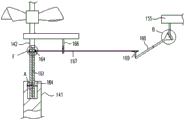
FIG. 1 is a schematic diagram of an environmental monitoring system for intelligent environmental engineering according to embodiment 1;
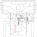
fig. 2 is a schematic structural diagram of an air collection test module according to embodiment 1;
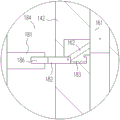
FIG. 3 is a schematic diagram of the unidirectional transmission mechanism and the detection driving mechanism in FIG. 2;
FIG. 4 is a schematic view of the structure of a fixed tooth and a movable tooth;
FIG. 5 is an enlarged view of a portion of the position A of FIG. 3;
FIG. 6 is an enlarged view of a portion of the B position of FIG. 3;
FIG. 7 is an enlarged view of a portion of the C position of FIG. 2;
FIG. 8 is an enlarged view of a portion of the D position of FIG. 2;
FIG. 9 is an enlarged view of a portion of the E position of FIG. 2;
FIG. 10 is an enlarged view of a portion of the F position of FIG. 3;
fig. 11 is a schematic structural diagram of an air collection test module provided in embodiment 2;
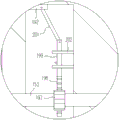
fig. 12 is a schematic view of the unidirectional transmission mechanism and the detection driving mechanism in fig. 11.
Icon:
11-gas collecting tube, 111-flow channel,
12-an air inlet pipe,
a 13-CO concentration sensor,
14-driving motor, 141-connecting shaft, 142-rotating shaft, 143-air suction fan blade,
151-accumulator, 152-generator, 153-drive shaft, 154-first gear, 155-movable shaft, 156-second gear,
161-lifting rod, 162-first connecting rod, 164-convex part, 165-avoiding opening, 166-guide plate, 167-cross rod, 168-rotating rod, 169-second connecting rod, 171-arc groove, 172-sliding block, 173-connecting ring,
181-fixed teeth, 182-movable teeth, 183-pressure springs, 184-connecting grooves, 185-planes, 186-inclined planes,
191-dustproof net, 192-knocking rod, 194-first bevel gear, 195-second bevel gear, 196-half bevel gear, 197-third gear, 198-first rack, 199-driving rod, 201-third connecting rod, 202-supporting block, 203-cover plate,
361-a one-way bearing, which is provided with a bearing,
381-first circulation pipe, 382-driven shaft, 383-second circulation pipe, 384-first driving block, 385-second driving block, 386-fourth link, 387-fifth link, 388-belt, 389-pulley, 391-fourth gear, 392-second rack, 393-third rack, 394-first driving blade, 395-second driving blade.
Detailed Description
Hereinafter, only certain exemplary embodiments are briefly described. As will be recognized by those of skill in the pertinent art, the described embodiments may be modified in numerous different ways without departing from the spirit or scope of the embodiments of the present invention.
In the description of embodiments of the present invention, it should be understood that the terms "longitudinal," "transverse," "upper," "lower," "left," "right," "inner," "clockwise," "circumferential," and the like indicate or are based on the orientation or positional relationship shown in the drawings, merely to facilitate description of embodiments of the present invention and to simplify the description, and do not indicate or imply that the devices or elements referred to must have a particular orientation, be configured and operated in a particular orientation, and thus should not be construed as limiting embodiments of the present invention.
Furthermore, the terms "first," "second," and the like, are used for descriptive purposes only and are not to be construed as indicating or implying a relative importance or implicitly indicating the number of technical features indicated. Thus, a feature defining "a first" or "a second" may explicitly or implicitly include one or more such feature. In the description of the embodiments of the present invention, the meaning of "plurality" is two or more, unless explicitly defined otherwise.
In the embodiments of the present invention, unless explicitly specified and limited otherwise, the terms "mounted," "connected," "secured" and the like are to be construed broadly and include, for example, either permanently connected, removably connected, or integrally formed; can be directly connected or indirectly connected through an intermediate medium, and can be communicated with the inside of two elements or the interaction relationship of the two elements. The specific meaning of the above terms in the embodiments of the present invention will be understood by those of ordinary skill in the art according to specific circumstances.
Embodiments of the present invention will be described in detail below with reference to the accompanying drawings.
Example 1
Referring to fig. 1 to 10, the present embodiment provides an environment monitoring system for intelligent environmental engineering, which mainly includes: the system comprises an air collection detection module, a data acquisition and transmission module, a central control processing module and a warning module, wherein the output end of the air collection detection module is connected with the input end of the data acquisition and transmission module; the data acquisition and transmission module, the central control processing module and the warning module are all of the prior art, and the air collection and detection module is mainly described below.
The air collection test module may mainly include: the gas-collecting tube 11, the gas-inlet tube 12, the CO concentration sensor 13, the driving motor 14, the storage battery 151, the generator 152 and the detection driving mechanism.
The inside of the header 11 has a flow passage 111 through which air passes.
The air inlet pipe 12 is communicated with the flow channel 111, the plurality of air inlet pipes 12 are uniformly distributed along the circumference of the air collecting pipe 11, and the air flowing in a plurality of directions can be collected or captured without rotating the air inlet pipe 12 and the air collecting pipe 11 in the use process, so that the detection accuracy and the monitoring range are improved, and the service life of the air inlet pipe 12 and the air collecting pipe 11 is prolonged.
The CO concentration sensor 13 is provided in the flow passage 111, and since the harmful component in the exhaust gas of the automobile is mainly CO, the degree of pollution of the air by the exhaust gas of the automobile can be reflected by detecting the concentration of CO in the air.
The driving motor 14 is arranged in the flow channel 111, and when air flows in the flow channel 111, heat generated when the driving motor 14 works can be taken away; the output end of the driving motor 14 is connected with a connecting shaft 141 in a transmission way, the connecting shaft 141 is connected with a rotating shaft 142 through a unidirectional transmission mechanism (namely, the connecting shaft 141 can unidirectionally drive the rotating shaft 142 to rotate), and the rotating shaft 142 is provided with an air suction fan blade 143 for sucking air in the external environment into the flow channel 111. The advantage of connecting the connecting shaft 141 and the rotating shaft 142 through the unidirectional transmission mechanism is that the air suction fan blade 143 and the rotating shaft 142 can rotate under the action of the driving motor 14, and also can rotate under the action of the air flowing in the flow channel 111, more specifically, the connecting shaft 141 can drive the rotating shaft 142 and the air suction fan blade 143 to rotate together in the weather with smaller wind force; in windy weather, the air suction fan blade 143 and the rotating shaft 142 can rotate at a higher speed than the rotating shaft 141, and the rotating shaft 142 does not rotate the connecting shaft 141 at a faster speed, or the rotating shaft 142 is not greatly hindered by the connecting shaft 141.
The storage battery 151 may supply power to the CO concentration sensor 13 as a backup power source, for example.
The output of generator 152 is connected with the input of battery 151 electricity, and the input of generator 152 is connected with pivot 142 through transmission shaft 153, first gear 154, loose axle 155 and second gear 156, and transmission shaft 153 is connected with the pivot 142 transmission, and first gear 154 is installed in transmission shaft 153, and loose axle 155 is pegged graft with the input of generator 152 (i.e. the input of generator 152) and can drive the input of generator 152 and rotate, and second gear 156 is installed in loose axle 155.
The detection driving mechanism is used for detecting a rotation speed difference between the rotating shaft 142 and the connecting shaft 141, and driving the movable shaft 155 to move so as to engage the second gear 156 with the first gear 154 when the rotation speed of the rotating shaft 142 is greater than the rotation speed of the connecting shaft 141, so that the input end of the generator 152 is driven to rotate by the rotating shaft 142 with a higher rotation speed to generate electricity.
As can be seen from the above description, by the arrangement of the unidirectional transmission mechanism, in windy weather, the rotational speed of the rotating shaft 142 can be higher than that of the connecting shaft 141 due to the faster air flow speed in the flow channel 111, at this time, the detection driving mechanism can drive the movable shaft 155 to move so as to engage the second gear 156 with the first gear 154, thereby driving the input end of the generator 152 to rotate for generating electricity, and storing the electric energy in the storage battery 151 to serve as a standby power source for supplying power to the CO concentration sensor 13, which is beneficial for reducing the overall energy consumption of the air collection detection module, and is beneficial for ensuring continuous operation of the CO concentration sensor 13, thereby better monitoring.
The main components and principles of the air collection test module are generally described above and will be described in greater detail below.
In this embodiment, the unidirectional transmission mechanism may mainly include: a fixed tooth 181, a movable tooth 182 and a compression spring 183; the connecting shaft 141 is provided with a connecting groove 184, and the fixed teeth 181 are annularly arranged on the side wall of the connecting groove 184; the movable teeth 182 are inserted into the rotating shaft 142, the upper side of the movable teeth 182 is a plane 185, and the lower side is an inclined plane 186 (up-down direction shown in fig. 4); one end of the pressure spring 183 is connected with the movable teeth 182, and the other end is connected with the rotating shaft 142; when the rotation speed of the rotating shaft 142 is less than or equal to the rotation speed of the connecting shaft 141, the plane 185 of the movable tooth 182 contacts with the fixed tooth 181, and at this time, the fixed tooth 181 on the connecting shaft 141 can drive the rotating shaft 142 to rotate through the movable tooth 182; when the rotation speed of the rotation shaft 142 is greater than that of the connection shaft 141, the rotation shaft 142 and the connection shaft 141 are relatively displaced as the rotation shaft 142 rotates, and when the inclined surface 186 of the movable tooth 182 contacts the fixed tooth 181, the fixed tooth 181 can push the movable tooth 182 toward the rotation shaft 142, so that the rotation shaft 142 can rotate at a faster speed than the connection shaft 141.
In this embodiment, the detection driving mechanism may mainly include: a lifting lever 161, a first link 162, and a transmission assembly; the lifting rod 161 is coaxial with the rotating shaft 142 and is connected in the rotating shaft 142 in a sliding way, a convex part 164 is fixed on the lifting rod 161, and an avoidance port 165 matched with the convex part 164 is formed on the rotating shaft 142; the first link 162 is inclined, one end of which is hinged with the lifting rod 161 and the other end of which is hinged with the movable teeth 182; the drive assembly is used to connect the boss 164 and the movable shaft 155.
As can be seen from the foregoing, in the present embodiment, the detection driving mechanism and the unidirectional transmission mechanism are cooperatively used, specifically, when the rotation speed of the rotating shaft 142 is greater than that of the connecting shaft 141, the inclined surface 186 of the movable tooth 182 contacts with the fixed tooth 181, the fixed tooth 181 can push the movable tooth 182 toward the rotating shaft 142, and the movable tooth 182 can drive the lifting rod 161 to move upwards through the first connecting rod 162 during the process that the movable tooth 182 is pushed toward the rotating shaft 142; after the inclined surface 186 of the movable tooth 182 is separated from the fixed tooth 181, the movable tooth 182 can move in a direction away from the rotating shaft 142 under the restoring force of the pressure spring 183 and drive the lifting rod 161 to move downwards; during the up-and-down movement of the lifting rod 161, the transmission assembly can drive the movable shaft 155 to do transverse reciprocating movement, so that the second gear 156 and the first gear 154 are intermittently engaged.
Specifically, the transmission assembly may mainly include: a guide plate 166, a rail 167, a pivot rod 168 and a second link 169; the guide plate 166 is fixed on the gas collecting tube 11, one end of the cross bar 167 is fixed with a connecting ring 173, the other end penetrates through the guide plate 166, the bottom of the connecting ring 173 is rotationally connected with the convex part 164, the cross bar 167 can longitudinally move along with the lifting rod 161, and the guide plate 166 plays a role in guiding the longitudinal movement of the cross bar 167; the middle part of the rotating rod 168 is rotationally connected with the gas collecting tube 11, one end of the rotating rod is provided with an arc groove 171, a sliding block 172 is slidably connected in the arc groove 171, and the sliding block 172 is hinged with the movable shaft 155; the lower end of the second link 169 is hinged to the pivot rod and the upper end is slidably connected to the rail 167, the upper end of the second link 169 being capable of sliding laterally relative to the rail 167 during longitudinal movement of the rail 167. When the lifting lever 161 moves upward, the cross bar 167 moves upward and drives the rotating lever 168 to rotate clockwise (clockwise as shown in fig. 3) through the second connecting rod 169, and the rotating lever 168 directly or indirectly drives the movable shaft 155 to move rightward, so that the second gear 156 on the movable shaft 155 is meshed with the first gear 154 on the transmission shaft 153.
It should be noted that, the transmission assembly is only a preferred embodiment for converting the longitudinal reciprocating movement of the lifting rod 161 into the transverse reciprocating movement of the movable shaft 155, and other structures may be adopted as long as the above purpose can be achieved, which is not illustrated in the present embodiment.
In order to avoid the influence of the detection effect of the CO concentration sensor 13 due to the dust in the air adhering to the CO concentration sensor 13 after entering the flow passage 111, a dust screen 191 is longitudinally arranged in the flow passage 111, and the air flows through the dust screen 191 and then through the CO concentration sensor 13 after entering the flow passage 111.
Further, in order to avoid clogging of the dust screen 191, the air collection detection module may further include: a tapping rod 192 and a reciprocating assembly; the knocking rod 192 is transversely inserted into the gas collecting tube 11; the reciprocating assembly is used to move the striking rod 192 laterally reciprocally so that the striking rod 192 intermittently strikes the dust screen 191 to knock off dust adhering to the dust screen 191, thereby reducing the probability of the dust screen 191 being blocked and ensuring smooth air flow in the flow passage 111.
Specifically, the reciprocating assembly may mainly include: a first bevel gear 194, a second bevel gear 195, a half bevel gear 196, a third gear 197, a first rack 198, a drive rod 199, a third link 201, and a support block 202; the first bevel gear 194 and the second bevel gear 195 are both mounted to the drive shaft 153; the half bevel gear 196 is installed at the upper part of the rotation shaft 142 and located between the first bevel gear 194 and the second bevel gear 195, and one side of the half bevel gear 196 is intermittently engaged with the first bevel gear 194 and the second bevel gear 195 during the rotation of the rotation shaft 142, so as to drive the transmission shaft 153 to reciprocate for self-transmission; the third gear 197 is mounted on the transmission shaft 153, the first rack 198 is meshed with the third gear 197, and when the transmission shaft 153 reciprocates self-transmission, the first rack 198 can be driven to longitudinally reciprocate; a drive rod 199 is fixed to one end of the first rack 198, the drive rod 199 being capable of longitudinally reciprocating with the first rack 198; one end of the third link 201 is hinged with the driving rod 199, and the other end is hinged with the knocking rod 192; the support block 202 is fixed on the gas collecting tube 11 and is inserted into the driving rod 199, and the support block 202 plays a role in guiding the longitudinal reciprocating movement of the driving rod 199. When the driving rod 199 moves up along with the first rack 198, the driving rod 199 drives the knocking rod 192 to move left (left and right directions shown in fig. 2) through the third connecting rod 201, so that the knocking rod 192 knocks on the dust screen 191; when the driving rod 199 moves downward with the first rack 198, the driving rod 199 drives the striking rod 192 to move rightward (left and right directions as viewed in fig. 2) via the third link 201 so that the striking rod 192 is away from the dust screen 191.
It should be noted that, the reciprocating assembly is only a preferred embodiment, and other structures may be adopted as long as the above purpose can be achieved, which is not shown in the present embodiment.
Further, referring to fig. 7, in order to facilitate cleaning of dust knocked off by the knocked rod 192 from the dust screen 191, the air collection and detection module may further include a cover 203 that can be opened and closed, where the cover 203 may be connected to an outer wall of the air collecting pipe 11 by a screw and disposed near one side of the dust screen 191, and after the cover 203 is opened, the dust knocked off by the knocked rod 192 from the dust screen 191 may be cleaned.
Example 2
This embodiment is another implementation of the unidirectional transmission mechanism and the detection driving mechanism of the air collection detection module.
Referring to fig. 11 and 12, in the present embodiment, the unidirectional transmission mechanism may mainly include a unidirectional bearing 361 in the prior art, specifically, the connection shaft 141 and the rotation shaft 142 are connected through the unidirectional bearing 361, and the unidirectional bearing 361 is configured to allow only the rotation shaft 142 to rotate in the same rotation direction as the connection shaft 141.
The detection driving mechanism may mainly include: the first circulating pipeline 381, the driven shaft 382, the second circulating pipeline 383, the first driving block 384, the second driving block 385, the fourth connecting rod 386 and the fifth connecting rod 387, wherein the first circulating pipeline 381 and the second circulating pipeline 383 are mutually independent and are in a shape of a Chinese character 'hui'; the first circulation pipe 381 is provided therein with a first driving vane 394 mounted to the rotation shaft 142, and the first driving vane 394 can drive the fluid in the first circulation pipe 381 to circulate; the driven shaft 382 is installed in the flow passage 111, the driven shaft 382 and the connecting shaft 141 are in transmission connection with each other through a belt 388 and a belt pulley 389, and the driven shaft 382 and the connecting shaft 141 can rotate at the same rotation speed; the second circulation pipe 383 is internally provided with a second driving blade 395 mounted on the driven shaft 382, and the second driving blade 395 can drive the fluid in the second circulation pipe 383 to circularly flow; the left side (left-right direction in fig. 12) of the first driving block 384 is arc-shaped and movably disposed in the first circulation pipe 381; the right side (left-right direction in fig. 12) of the second driving block 385 is arc-shaped and movably disposed in the second circulation duct 383; the first driving block 384 and the second driving block 385 are symmetrically fixed at both ends of the fourth link 386; one end of the fifth link 387 is fixed to the middle of the fourth link 386, and the other end is connected to the movable shaft 155 through a reversing assembly.
As can be seen from the above description, similar to the principle of aircraft takeoff, since the left side of the first driving block 384 is curved, the flow velocity of the left side of the first driving block 384 is faster, and according to the bernoulli principle, the pressure applied to the left side of the first driving block 384 is smaller than the pressure applied to the right side of the first driving block 384, so that the first driving block 384 tends to move leftwards; because the right side of the second driving block 385 is arc-shaped, the flow velocity of the right side of the second driving block 385 is faster, and the pressure applied to the right side of the second driving block 385 is smaller than the pressure applied to the left side of the second driving block 385 according to the Bernoulli principle, so that the second driving block 385 tends to move rightwards; the driven shaft 382 and the connecting shaft 141 can always rotate at the same rotation speed, when the rotation speed of the rotating shaft 142 is equal to the rotation speed of the connecting shaft 141, the left acting force applied to the first driving block 384 and the right acting force applied to the second driving block 385 cancel each other, and the fifth connecting rod 387 can be maintained at the current position; when the rotation speed of the rotating shaft 142 is greater than that of the connecting shaft 141, the leftward acting force applied to the first driving block 384 increases, and the fifth connecting rod 387 can move leftward, so that the reversing assembly drives the movable shaft 155 to move rightward, the second gear 156 and the first gear 154 are meshed, and the rotating shaft 142 with a higher rotation speed drives the input end of the generator 152 to rotate to generate electricity.
Specifically, the reversing assembly may mainly include a fourth gear 391, and a second rack 392 and a third rack 393 respectively engaged on the upper and lower sides of the fourth gear 391; the fourth gear 391 is rotatably mounted in the runner 111, the second rack 392 is fixedly coupled to the fifth link 387, and the third rack 393 is fixedly coupled to the movable shaft 155.
It should be noted that, the reversing assembly is only a preferred embodiment for converting the leftward (or rightward) movement of the fifth link 387 into the rightward (or leftward) movement of the movable shaft 155, and the reversing assembly may also have other structures, so long as the above purpose can be achieved, which is not illustrated in this embodiment.
As is apparent from the above, the detection driving mechanism provided in this embodiment is more advantageous in that the second gear 156 and the first gear 154 are kept in a meshed state when the external wind speed is high and the rotational speed of the rotating shaft 142 is greater than the rotational speed of the connecting shaft 141, as compared with embodiment 1.
Finally, it should be noted that: the above is only a preferred embodiment of the present invention, and is not intended to limit the present invention, and various modifications and changes may be made to the present invention by those skilled in the art, and the embodiments and features of the embodiments of the present application may be arbitrarily combined with each other without collision. Any modification, equivalent replacement, improvement, etc. made within the spirit and principle of the present invention should be included in the protection scope of the present invention.
Claims (10)
1. The utility model provides an wisdom environmental protection is environment monitoring system for engineering, includes air collection detection module, data acquisition transmission module, central control processing module and warning module, its characterized in that, air collection detection module includes:
a gas collecting tube, the inside of which is provided with a flow passage for air to pass through;
the air inlet pipes are communicated with the flow channels, and a plurality of air inlet pipes are distributed along the circumferential direction of the air collecting pipe;
the CO concentration sensor is arranged in the flow channel;
the driving motor is arranged in the flow channel, the output end of the driving motor is in transmission connection with a connecting shaft, the connecting shaft is connected with a rotating shaft through a unidirectional transmission mechanism, and the rotating shaft is provided with an air suction fan blade;
a storage battery for supplying power to the CO concentration sensor;
the output end of the generator is electrically connected with the input end of the storage battery, the input end of the generator is connected with the rotating shaft through a transmission shaft, a first gear, a movable shaft and a second gear, the transmission shaft is in transmission connection with the rotating shaft, the first gear is arranged on the transmission shaft, the movable shaft is connected with the input end of the generator in an inserting mode and can drive the input end of the generator to rotate, and the second gear is arranged on the movable shaft; a kind of electronic device with high-pressure air-conditioning system
And the detection driving mechanism is used for detecting the rotating speed difference between the rotating shaft and the connecting shaft, and driving the movable shaft to move so as to enable the second gear to be meshed with the first gear when the rotating speed of the rotating shaft is larger than that of the connecting shaft.
2. The intelligent environmental monitoring system for environmental engineering according to claim 1, wherein the unidirectional transmission mechanism comprises:
the connecting shaft is provided with a connecting groove, and the fixed teeth are annularly arranged on the side wall of the connecting groove;
the movable teeth are spliced with the rotating shaft, and two opposite sides of the movable teeth are respectively a plane and an inclined plane; a kind of electronic device with high-pressure air-conditioning system
One end of the pressure spring is connected with the movable tooth, and the other end of the pressure spring is connected with the rotating shaft;
when the rotating speed of the rotating shaft is smaller than or equal to that of the connecting shaft, the plane is in contact with the fixed teeth; when the rotating speed of the rotating shaft is greater than that of the connecting shaft, the inclined surface is in contact with the fixed teeth.
3. The intelligent environmental monitoring system for environmental engineering according to claim 2, wherein the detection driving mechanism comprises:
the lifting rod is coaxial with the rotating shaft and is connected in the rotating shaft in a sliding way, a convex part is fixed on the lifting rod, and an avoidance port matched with the convex part is formed in the rotating shaft;
one end of the first connecting rod is hinged with the lifting rod, and the other end of the first connecting rod is hinged with the movable teeth; a kind of electronic device with high-pressure air-conditioning system
And the transmission assembly is used for connecting the convex part and the movable shaft.
4. The intelligent environmental monitoring system for environmental engineering according to claim 3, wherein the transmission assembly comprises:
the guide plate is fixed on the gas collecting tube;
the connecting ring is fixed at one end of the cross rod, the other end of the cross rod penetrates through the guide plate, the bottom of the connecting ring is rotationally connected with the convex part, and the cross rod can longitudinally move along with the lifting rod;
the middle part of the rotating rod is rotationally connected with the gas collecting tube, one end of the rotating rod is provided with an arc-shaped groove, a sliding block is connected in the arc-shaped groove in a sliding way, and the sliding block is hinged with the movable shaft; a kind of electronic device with high-pressure air-conditioning system
And one end of the second connecting rod is hinged with the rotating rod, and the other end of the second connecting rod is in sliding connection with the cross rod.
5. The environmental monitoring system for intelligent environmental protection engineering according to any one of claims 1 to 4, wherein a dust screen is arranged in the flow channel, and air flows through the dust screen and then through the CO concentration sensor after entering the flow channel.
6. The intelligent environmental monitoring system for environmental engineering according to claim 5, wherein the air collection and detection module further comprises:
the knocking rod is spliced with the gas collecting tube;
the reciprocating assembly is used for transversely reciprocating the knocking rod so that the knocking rod intermittently knocks on the dust screen; a kind of electronic device with high-pressure air-conditioning system
The cover plate capable of being opened and closed is connected to the outer wall of the gas collecting tube and is arranged close to one side of the dust screen.
7. The intelligent environmental monitoring system for environmental engineering according to claim 6, wherein the reciprocating assembly comprises:
a first bevel gear mounted to the drive shaft;
the second bevel gear is arranged on the transmission shaft;
the half bevel gear is arranged on the rotating shaft, and one side of the half bevel gear is intermittently meshed with the first bevel gear and the second bevel gear;
the third gear is arranged on the transmission shaft;
a first rack engaged with the third gear;
the driving rod is fixed at one end of the first rack;
one end of the third connecting rod is hinged with the driving rod, and the other end of the third connecting rod is hinged with the knocking rod; a kind of electronic device with high-pressure air-conditioning system
The support block is fixed on the gas collecting tube and is spliced with the driving rod.
8. The intelligent environmental monitoring system for environmental engineering according to claim 1, wherein the unidirectional transmission mechanism comprises a unidirectional bearing.
9. The intelligent environmental monitoring system for environmental engineering according to claim 1, wherein the detection driving mechanism comprises:
a first circulation pipe in which a first driving blade mounted to the rotation shaft is disposed;
the driven shaft rotates at the same rotating speed with the connecting shaft;
a second circulation pipe in which a second driving blade mounted to the driven shaft is provided;
one side of the first driving block is arc-shaped and is movably arranged in the first circulating pipeline;
one side of the second driving block is arc-shaped and is movably arranged in the second circulating pipeline;
the first driving block and the second driving block are symmetrically fixed at two ends of the fourth connecting rod; a kind of electronic device with high-pressure air-conditioning system
And one end of the fifth connecting rod is fixed at the middle part of the fourth connecting rod, and the other end of the fifth connecting rod is connected with the movable shaft through a reversing assembly.
10. The intelligent environmental monitoring system for environmental engineering according to claim 9, wherein the reversing assembly comprises a fourth gear and a second rack and a third rack respectively engaged on opposite sides of the fourth gear; the second rack is fixedly connected with the fifth connecting rod, and the third rack is fixedly connected with the movable shaft.
Priority Applications (1)
| Application Number | Priority Date | Filing Date | Title |
|---|---|---|---|
| CN202310484907.9A CN116183840B (en) | 2023-05-04 | 2023-05-04 | Environment monitoring system for intelligent environmental protection engineering |
Applications Claiming Priority (1)
| Application Number | Priority Date | Filing Date | Title |
|---|---|---|---|
| CN202310484907.9A CN116183840B (en) | 2023-05-04 | 2023-05-04 | Environment monitoring system for intelligent environmental protection engineering |
Publications (2)
| Publication Number | Publication Date |
|---|---|
| CN116183840A true CN116183840A (en) | 2023-05-30 |
| CN116183840B CN116183840B (en) | 2023-06-30 |
Family
ID=86446659
Family Applications (1)
| Application Number | Title | Priority Date | Filing Date |
|---|---|---|---|
| CN202310484907.9A Active CN116183840B (en) | 2023-05-04 | 2023-05-04 | Environment monitoring system for intelligent environmental protection engineering |
Country Status (1)
| Country | Link |
|---|---|
| CN (1) | CN116183840B (en) |
Cited By (1)
| Publication number | Priority date | Publication date | Assignee | Title |
|---|---|---|---|---|
| CN116930434A (en) * | 2023-09-19 | 2023-10-24 | 山西智达建筑工程检测有限公司 | Indoor pollutant detection device |
Citations (21)
| Publication number | Priority date | Publication date | Assignee | Title |
|---|---|---|---|---|
| WO1986001563A2 (en) * | 1984-08-23 | 1986-03-13 | Jaeckel Ernst | Jet-engine type drive system for wind-mills |
| EP0229001A1 (en) * | 1986-01-08 | 1987-07-15 | Ettore Valentino Martines | Vertical axis windmill converting wind energy into heat |
| CA2464931A1 (en) * | 2003-04-18 | 2004-10-18 | Fuji Jukogyo Kabushiki Kaisha | Continuously variable transmission |
| US20070222223A1 (en) * | 2006-03-22 | 2007-09-27 | General Electric Company | Wind turbine generators having wind assisted cooling systems and cooling methods |
| CN201443470U (en) * | 2009-08-01 | 2010-04-28 | 许孝礼 | Rotor of large sail vertical rotating wind power generator |
| CN102926933A (en) * | 2011-08-13 | 2013-02-13 | 鲁小和 | Suspension type horizontal-axis wind generator with buoyancy force overcoming force of gravity and elastic force |
| US20130200618A1 (en) * | 2012-02-02 | 2013-08-08 | Mark Albert Prindle | High efficiency wind turbine |
| CN103296951A (en) * | 2013-05-29 | 2013-09-11 | 哈尔滨工业大学 | Control method of birotor-structure variable-speed constant-frequency wind power generation system |
| WO2017160825A1 (en) * | 2016-03-15 | 2017-09-21 | Accelerated Technologies Corporation | Wind energy harvesting utilizing air shaft and centrifugal impellor wheels |
| CN108645981A (en) * | 2018-07-19 | 2018-10-12 | 湖州御筵科技有限公司 | A kind of new energy environment monitoring device |
| CN109489706A (en) * | 2018-11-07 | 2019-03-19 | 王振骁 | A kind of new energy environment monitoring device |
| CN111319602A (en) * | 2020-04-20 | 2020-06-23 | 广州有源船舶科技有限公司 | Full-airflow-to-electric-energy-driven metal air cushion jet recovery ship structure and power generation device |
| CN112145341A (en) * | 2019-06-28 | 2020-12-29 | 泓星科技有限公司 | Vertical shaft type wind driven generator |
| CN112593898A (en) * | 2020-11-30 | 2021-04-02 | 内蒙古民族大学 | Wind power hybrid power driven oil pumping unit system and working method thereof |
| CN112796933A (en) * | 2020-12-30 | 2021-05-14 | 孟娜妮 | Fan blade rotating device for wind power generation |
| CN112848870A (en) * | 2021-01-29 | 2021-05-28 | 金陵科技学院 | Air inlet and exhaust gas turbocharging power generation hybrid power system and control method |
| CN112901415A (en) * | 2021-03-06 | 2021-06-04 | 湘电风能有限公司 | Starting control method, device, controller and system of wind generating set |
| CN216111362U (en) * | 2021-06-29 | 2022-03-22 | 闫广志 | Volute type energy-saving fan |
| CN114384212A (en) * | 2022-03-23 | 2022-04-22 | 武汉贺为科技有限公司 | Intelligent environment-friendly air monitoring system, method and equipment |
| CN115711201A (en) * | 2022-11-30 | 2023-02-24 | 三一重能股份有限公司 | Wind power generation energy storage system, wind power generator and wind power generation energy storage control method |
| CN116044694A (en) * | 2022-09-18 | 2023-05-02 | 黄竹山 | Mechanism for obtaining moment and device thereof |
-
2023
- 2023-05-04 CN CN202310484907.9A patent/CN116183840B/en active Active
Patent Citations (21)
| Publication number | Priority date | Publication date | Assignee | Title |
|---|---|---|---|---|
| WO1986001563A2 (en) * | 1984-08-23 | 1986-03-13 | Jaeckel Ernst | Jet-engine type drive system for wind-mills |
| EP0229001A1 (en) * | 1986-01-08 | 1987-07-15 | Ettore Valentino Martines | Vertical axis windmill converting wind energy into heat |
| CA2464931A1 (en) * | 2003-04-18 | 2004-10-18 | Fuji Jukogyo Kabushiki Kaisha | Continuously variable transmission |
| US20070222223A1 (en) * | 2006-03-22 | 2007-09-27 | General Electric Company | Wind turbine generators having wind assisted cooling systems and cooling methods |
| CN201443470U (en) * | 2009-08-01 | 2010-04-28 | 许孝礼 | Rotor of large sail vertical rotating wind power generator |
| CN102926933A (en) * | 2011-08-13 | 2013-02-13 | 鲁小和 | Suspension type horizontal-axis wind generator with buoyancy force overcoming force of gravity and elastic force |
| US20130200618A1 (en) * | 2012-02-02 | 2013-08-08 | Mark Albert Prindle | High efficiency wind turbine |
| CN103296951A (en) * | 2013-05-29 | 2013-09-11 | 哈尔滨工业大学 | Control method of birotor-structure variable-speed constant-frequency wind power generation system |
| WO2017160825A1 (en) * | 2016-03-15 | 2017-09-21 | Accelerated Technologies Corporation | Wind energy harvesting utilizing air shaft and centrifugal impellor wheels |
| CN108645981A (en) * | 2018-07-19 | 2018-10-12 | 湖州御筵科技有限公司 | A kind of new energy environment monitoring device |
| CN109489706A (en) * | 2018-11-07 | 2019-03-19 | 王振骁 | A kind of new energy environment monitoring device |
| CN112145341A (en) * | 2019-06-28 | 2020-12-29 | 泓星科技有限公司 | Vertical shaft type wind driven generator |
| CN111319602A (en) * | 2020-04-20 | 2020-06-23 | 广州有源船舶科技有限公司 | Full-airflow-to-electric-energy-driven metal air cushion jet recovery ship structure and power generation device |
| CN112593898A (en) * | 2020-11-30 | 2021-04-02 | 内蒙古民族大学 | Wind power hybrid power driven oil pumping unit system and working method thereof |
| CN112796933A (en) * | 2020-12-30 | 2021-05-14 | 孟娜妮 | Fan blade rotating device for wind power generation |
| CN112848870A (en) * | 2021-01-29 | 2021-05-28 | 金陵科技学院 | Air inlet and exhaust gas turbocharging power generation hybrid power system and control method |
| CN112901415A (en) * | 2021-03-06 | 2021-06-04 | 湘电风能有限公司 | Starting control method, device, controller and system of wind generating set |
| CN216111362U (en) * | 2021-06-29 | 2022-03-22 | 闫广志 | Volute type energy-saving fan |
| CN114384212A (en) * | 2022-03-23 | 2022-04-22 | 武汉贺为科技有限公司 | Intelligent environment-friendly air monitoring system, method and equipment |
| CN116044694A (en) * | 2022-09-18 | 2023-05-02 | 黄竹山 | Mechanism for obtaining moment and device thereof |
| CN115711201A (en) * | 2022-11-30 | 2023-02-24 | 三一重能股份有限公司 | Wind power generation energy storage system, wind power generator and wind power generation energy storage control method |
Non-Patent Citations (2)
| Title |
|---|
| ZHENG LV 等: "Data imputation for gas flow data in steel industry based on non-equal-length granules correlation coefficient", 《INFORMATION SCIENCES》, no. 367, pages 311 - 323, XP029676254, DOI: 10.1016/j.ins.2016.05.046 * |
| 李少华;岳巍澎;王东华;岳征;: "基于CFD的旋转风轮气动性能分析", 动力工程学报, no. 09, pages 705 - 708 * |
Cited By (2)
| Publication number | Priority date | Publication date | Assignee | Title |
|---|---|---|---|---|
| CN116930434A (en) * | 2023-09-19 | 2023-10-24 | 山西智达建筑工程检测有限公司 | Indoor pollutant detection device |
| CN116930434B (en) * | 2023-09-19 | 2023-11-17 | 山西智达建筑工程检测有限公司 | Indoor pollutant detection device |
Also Published As
| Publication number | Publication date |
|---|---|
| CN116183840B (en) | 2023-06-30 |
Similar Documents
| Publication | Publication Date | Title |
|---|---|---|
| CN116183840B (en) | Environment monitoring system for intelligent environmental protection engineering | |
| EP2639440A1 (en) | Engine exhaust gas purification device | |
| CN101710035A (en) | Smoke dust sampling instrument | |
| KR20050012110A (en) | Ship Having Apparatus which Generates Electricity Using the Force of Wind, Water and Sun heat | |
| CN213749796U (en) | Environmental air pollution monitoring micro station | |
| CN113065040A (en) | Electric power data analysis system based on 5G communication | |
| CN101539114A (en) | Wind motor utilizing compressed air to do work | |
| CN211179178U (en) | Novel CEMS system's full system calibration sample thief | |
| CN209564729U (en) | A kind of air contaminant treatment engineering regenerative electric power equipment | |
| CN111120158A (en) | Small-size petrol engine low temperature ignition guarantee device of unmanned aerial vehicle | |
| CN215066528U (en) | Automobile exhaust tail gas detection device | |
| CN216053012U (en) | Active safety on-line monitoring and early warning device for lithium ion battery energy storage power station | |
| CN212620353U (en) | Intelligent dust removing equipment | |
| CN215734178U (en) | Solar wireless power supply device for vehicle-mounted sensor | |
| CN213981075U (en) | Cooling device of wind driven generator | |
| CN218669700U (en) | Box air compressor of environmental protection | |
| CN217954197U (en) | Oil smoke on-line monitoring device | |
| CN213997037U (en) | Server dust collector and have dust removal function's server | |
| CN213450666U (en) | Combined type wind collecting head for wind driven generator | |
| CN220705991U (en) | Environment-friendly dust removal main fan | |
| CN213478399U (en) | Novel pneumatic device | |
| CN211648335U (en) | Small-size petrol engine low temperature ignition guarantee device of unmanned aerial vehicle | |
| CN217247560U (en) | Environment-friendly is tail gas treatment structure for bioengineering | |
| CN111391637A (en) | New energy automobile air duct cooling device | |
| CN215525933U (en) | Take voltage acquisition module of dustproof function |
Legal Events
| Date | Code | Title | Description |
|---|---|---|---|
| PB01 | Publication | ||
| PB01 | Publication | ||
| SE01 | Entry into force of request for substantive examination | ||
| SE01 | Entry into force of request for substantive examination | ||
| GR01 | Patent grant | ||
| GR01 | Patent grant |