CN116172276A - Aerosol generating device and aerosol generating device control method - Google Patents
Aerosol generating device and aerosol generating device control method Download PDFInfo
- Publication number
- CN116172276A CN116172276A CN202211696170.9A CN202211696170A CN116172276A CN 116172276 A CN116172276 A CN 116172276A CN 202211696170 A CN202211696170 A CN 202211696170A CN 116172276 A CN116172276 A CN 116172276A
- Authority
- CN
- China
- Prior art keywords
- heater
- mode
- aerosol
- temperature
- battery
- Prior art date
- Legal status (The legal status is an assumption and is not a legal conclusion. Google has not performed a legal analysis and makes no representation as to the accuracy of the status listed.)
- Pending
Links
Images


Classifications
-
- A—HUMAN NECESSITIES
- A24—TOBACCO; CIGARS; CIGARETTES; SIMULATED SMOKING DEVICES; SMOKERS' REQUISITES
- A24F—SMOKERS' REQUISITES; MATCH BOXES; SIMULATED SMOKING DEVICES
- A24F40/00—Electrically operated smoking devices; Component parts thereof; Manufacture thereof; Maintenance or testing thereof; Charging means specially adapted therefor
- A24F40/65—Devices with integrated communication means, e.g. Wi-Fi
-
- A—HUMAN NECESSITIES
- A24—TOBACCO; CIGARS; CIGARETTES; SIMULATED SMOKING DEVICES; SMOKERS' REQUISITES
- A24B—MANUFACTURE OR PREPARATION OF TOBACCO FOR SMOKING OR CHEWING; TOBACCO; SNUFF
- A24B15/00—Chemical features or treatment of tobacco; Tobacco substitutes, e.g. in liquid form
- A24B15/10—Chemical features of tobacco products or tobacco substitutes
- A24B15/16—Chemical features of tobacco products or tobacco substitutes of tobacco substitutes
-
- A—HUMAN NECESSITIES
- A24—TOBACCO; CIGARS; CIGARETTES; SIMULATED SMOKING DEVICES; SMOKERS' REQUISITES
- A24F—SMOKERS' REQUISITES; MATCH BOXES; SIMULATED SMOKING DEVICES
- A24F40/00—Electrically operated smoking devices; Component parts thereof; Manufacture thereof; Maintenance or testing thereof; Charging means specially adapted therefor
- A24F40/40—Constructional details, e.g. connection of cartridges and battery parts
- A24F40/46—Shape or structure of electric heating means
-
- A—HUMAN NECESSITIES
- A24—TOBACCO; CIGARS; CIGARETTES; SIMULATED SMOKING DEVICES; SMOKERS' REQUISITES
- A24F—SMOKERS' REQUISITES; MATCH BOXES; SIMULATED SMOKING DEVICES
- A24F40/00—Electrically operated smoking devices; Component parts thereof; Manufacture thereof; Maintenance or testing thereof; Charging means specially adapted therefor
- A24F40/50—Control or monitoring
- A24F40/51—Arrangement of sensors
-
- A—HUMAN NECESSITIES
- A24—TOBACCO; CIGARS; CIGARETTES; SIMULATED SMOKING DEVICES; SMOKERS' REQUISITES
- A24F—SMOKERS' REQUISITES; MATCH BOXES; SIMULATED SMOKING DEVICES
- A24F40/00—Electrically operated smoking devices; Component parts thereof; Manufacture thereof; Maintenance or testing thereof; Charging means specially adapted therefor
- A24F40/50—Control or monitoring
- A24F40/57—Temperature control
-
- A—HUMAN NECESSITIES
- A24—TOBACCO; CIGARS; CIGARETTES; SIMULATED SMOKING DEVICES; SMOKERS' REQUISITES
- A24F—SMOKERS' REQUISITES; MATCH BOXES; SIMULATED SMOKING DEVICES
- A24F40/00—Electrically operated smoking devices; Component parts thereof; Manufacture thereof; Maintenance or testing thereof; Charging means specially adapted therefor
- A24F40/60—Devices with integrated user interfaces
-
- A—HUMAN NECESSITIES
- A24—TOBACCO; CIGARS; CIGARETTES; SIMULATED SMOKING DEVICES; SMOKERS' REQUISITES
- A24F—SMOKERS' REQUISITES; MATCH BOXES; SIMULATED SMOKING DEVICES
- A24F40/00—Electrically operated smoking devices; Component parts thereof; Manufacture thereof; Maintenance or testing thereof; Charging means specially adapted therefor
- A24F40/85—Maintenance, e.g. cleaning
-
- A—HUMAN NECESSITIES
- A24—TOBACCO; CIGARS; CIGARETTES; SIMULATED SMOKING DEVICES; SMOKERS' REQUISITES
- A24F—SMOKERS' REQUISITES; MATCH BOXES; SIMULATED SMOKING DEVICES
- A24F40/00—Electrically operated smoking devices; Component parts thereof; Manufacture thereof; Maintenance or testing thereof; Charging means specially adapted therefor
- A24F40/90—Arrangements or methods specially adapted for charging batteries thereof
-
- A—HUMAN NECESSITIES
- A61—MEDICAL OR VETERINARY SCIENCE; HYGIENE
- A61M—DEVICES FOR INTRODUCING MEDIA INTO, OR ONTO, THE BODY; DEVICES FOR TRANSDUCING BODY MEDIA OR FOR TAKING MEDIA FROM THE BODY; DEVICES FOR PRODUCING OR ENDING SLEEP OR STUPOR
- A61M15/00—Inhalators
- A61M15/06—Inhaling appliances shaped like cigars, cigarettes or pipes
-
- A—HUMAN NECESSITIES
- A24—TOBACCO; CIGARS; CIGARETTES; SIMULATED SMOKING DEVICES; SMOKERS' REQUISITES
- A24F—SMOKERS' REQUISITES; MATCH BOXES; SIMULATED SMOKING DEVICES
- A24F40/00—Electrically operated smoking devices; Component parts thereof; Manufacture thereof; Maintenance or testing thereof; Charging means specially adapted therefor
- A24F40/20—Devices using solid inhalable precursors
-
- Y—GENERAL TAGGING OF NEW TECHNOLOGICAL DEVELOPMENTS; GENERAL TAGGING OF CROSS-SECTIONAL TECHNOLOGIES SPANNING OVER SEVERAL SECTIONS OF THE IPC; TECHNICAL SUBJECTS COVERED BY FORMER USPC CROSS-REFERENCE ART COLLECTIONS [XRACs] AND DIGESTS
- Y02—TECHNOLOGIES OR APPLICATIONS FOR MITIGATION OR ADAPTATION AGAINST CLIMATE CHANGE
- Y02E—REDUCTION OF GREENHOUSE GAS [GHG] EMISSIONS, RELATED TO ENERGY GENERATION, TRANSMISSION OR DISTRIBUTION
- Y02E60/00—Enabling technologies; Technologies with a potential or indirect contribution to GHG emissions mitigation
- Y02E60/10—Energy storage using batteries
Abstract
An aerosol-generating device according to the present invention includes a power supply unit including a first battery and a second battery, a control unit configured to control the power supply unit to operate in either a first mode in which power is supplied to the heater by the first battery or a second mode in which power is supplied to the heater by the second battery, and to control the power supply unit to supply greater power to the heater in the first mode than in the second mode.
Description
The present application is a divisional application with application number 2018800463673, application date 2018, 8, 9, and the name of "aerosol generating device and control method of aerosol generating device".
Technical Field
The present invention relates to an aerosol-generating device and a method for controlling an aerosol-generating device, and more particularly, to an aerosol-generating device including an electric power supply source capable of being rapidly recharged and providing a high output, and a method for controlling an aerosol-generating device.
Background
Existing electrically operated aerosol-generating devices are of similar size to cigarettes and include a heater and a battery for heating an aerosol-generating article. The battery is able to provide a high output to the heater of the aerosol-generating device for a period of a few minutes. The battery included in the aerosol-generating device may be a battery that is capable of recharging hundreds to thousands of cycles for a new smoking activity (session).
In one aspect, the aerosol-generating device may operate by detecting inhalation by a user. Upon detection of inhalation by a user, a heater included in the aerosol-generating device may be heated to a temperature sufficient to generate an aerosol from an aerosol-forming mechanism of the aerosol-generating article. After the heater is heated to a temperature sufficient for aerosol generation, the aerosol-generating device may maintain the temperature of the heater at an appropriate level until the user continues to smoke.
A user of the aerosol-generating device is smoking a heater that wishes to be able to rapidly heat the aerosol-generating device. In addition, a user may wish to charge the aerosol-generating device at a high rate for a new smoking event after one smoking event.
Disclosure of Invention
Problems to be solved by the invention
Provided is an electric power source capable of rapidly heating a heater of an aerosol-generating device and capable of charging the aerosol-generating device at a high speed.
By providing the aerosol-generating device with a plurality of power sources, the plurality of power sources can be selectively operated according to the need for high output and the need for unnecessary conditions in the aerosol-generating device.
Means for solving the problems
A method of selectively operating a plurality of power sources according to a case where a high output is required and a case where the high output is not required in an aerosol-generating device using the plurality of power sources is proposed.
Effects of the invention
According to the disclosed embodiments, a heater capable of rapidly heating an aerosol-generating device and a power source capable of high-speed charging of the aerosol-generating device may be provided.
According to the disclosed embodiments, by providing a plurality of power sources in the aerosol-generating device, the plurality of power sources can be selectively operated according to the case where high output is required and the case where high output is not required in the aerosol-generating device.
Drawings
Fig. 1 is a block diagram illustrating an aerosol-generating device 100 of an embodiment.
Fig. 2 is another block diagram illustrating an aerosol-generating device 100 of an embodiment.
Fig. 3 is a flow chart illustrating a method of controlling an aerosol-generating device according to an embodiment.
Fig. 4 is another flow chart illustrating a method of controlling an aerosol-generating device according to an embodiment.
Fig. 5 is a diagram generally illustrating a circuit diagram of an aerosol-generating device 100 of an embodiment.
Fig. 6 is a block diagram showing an example of the aerosol-generating device.
Fig. 7A and 7B are diagrams showing an example of the retainer from a plurality of sides.
Fig. 8 is a structural view showing an example of the bracket.
Fig. 9A and 9B are diagrams showing an example of the bracket from a plurality of sides.
Fig. 10 is a view showing an example of the holder insertion bracket.
Fig. 11 is a view showing an example of tilting in a state in which the holder is inserted into the bracket.
Fig. 12A to 12B are diagrams showing an example in which a holder is inserted into a bracket.
Fig. 13 is a flowchart for explaining an example of the operation of the holder and the bracket.
Fig. 14 is a flowchart for explaining an example of the retainer operation.
Fig. 15 is a flowchart for explaining an example of the operation of the carriage.
Fig. 16 is a view showing an example of the cigarette insertion holder.
Fig. 17A and 17B are block diagrams showing an example of cigarettes.
Fig. 18A to 18F are diagrams showing examples of the cooling structure of the cigarette.
Detailed Description
An aerosol-generating device according to an embodiment includes a power supply unit having a first battery and a second battery, a control unit operable to control the power supply unit to operate in either a first mode in which power is supplied to the heater by the first battery or a second mode in which power is supplied to the heater by the second battery, and a heater, the control unit operable to control the power supply unit to supply greater power to the heater in the first mode than in the second mode.
The first mode of an embodiment may be a mode for increasing the temperature of the heater, and the second mode may be a mode for maintaining the temperature of the heater.
The first battery of an embodiment may include a lithium ion capacitor.
The second battery of an embodiment may include one of a lithium ion battery, a lithium iron phosphate battery, a lithium titanate battery, and a lithium polymer (lithium polymer) battery.
The aerosol-generating device of an embodiment may further comprise a sensor for detecting inhalation by the user, the control portion of an embodiment being operable to control the power supply portion to operate in the first mode when inhalation is detected.
The aerosol-generating device of an embodiment further comprises a sensor for detecting inhalation by a user and a sensor for detecting the temperature of the heater, and the control section of an embodiment controls the power supply section to operate in the first mode when the temperature of the heater is below the first temperature and in the second mode when the temperature of the heater is above the first temperature when inhalation is detected.
A control part of an embodiment can control the power supply part to work according to a first mode during the period that the temperature of the heater rises to the critical temperature; and the power supply part can be controlled to operate according to the second mode when the temperature of the heater reaches above the critical temperature.
The control portion of an embodiment may control the power supply portion to operate in the first mode during a first time period, and may control the power supply portion to operate in the second mode after the first time period has elapsed.
The aerosol-generating device of an embodiment, further comprises a memory for storing a condition for switching from the first mode to the second mode,
conditions of an embodiment may include a temperature of the heater and a time for the power supply portion to operate in the first mode.
A control method of an aerosol-generating device of an embodiment, comprising:
when the inhalation of the user is detected, controlling the power supply part to operate according to a first mode of supplying power to the heater by using the first battery when the temperature of the heater is lower than a first temperature, and
a step of controlling the power supply unit to operate in either a first mode or a second mode in which power is supplied to the heater by the second battery, based on the temperature of the heater or the time for which the power supply unit operates in the first mode; the power supply portion of an embodiment supplies greater power to the heater in the first mode than in the second mode.
The first mode of an embodiment is a mode for increasing the temperature of the heater, and the second mode is a mode for maintaining the temperature of the heater.
The first battery of an embodiment may include a lithium ion capacitor.
The second battery of an embodiment may include one of a lithium ion battery, a lithium iron phosphate battery, a lithium titanate battery, and a lithium polymer (lithium polymer) battery.
The control method of the aerosol-generating device of an embodiment further comprises: and a step of controlling the power supply part to operate according to the second mode when the temperature of the heater is greater than the first temperature when the inhalation is detected.
The aerosol-generating device control method of an embodiment comprises:
a step of controlling the power supply unit to operate in a first mode while the temperature of the heater is rising to a critical temperature; a kind of electronic device with high-pressure air-conditioning system
And a step of controlling the power supply unit to operate in the second mode when the temperature of the heater is equal to or higher than the critical temperature.
An aerosol-generating device control method of an embodiment, comprising:
a step of controlling the power supply unit to operate in a first mode during a first time period; a kind of electronic device with high-pressure air-conditioning system
And a step of controlling the power supply unit to operate in the second mode after the first time elapses.
Hereinafter, exemplary embodiments of the present invention will be described in detail with reference to the drawings. Further, the configuration of the electronic device according to the embodiment of the present invention and the method of using the same will be described in detail with reference to the drawings. The same reference numerals or symbols in the drawings indicate components or elements that perform substantially the same function.
Terms including ordinal numbers such as first, second, etc., may be used to describe various elements, but the elements are not limited by the terms. The term is used merely to distinguish one component from another. For example, a first component may be termed a second component, and, similarly, a second component may be termed a first component, without departing from the scope of the present invention. The term "and/or" includes a combination of a plurality of related items or any of a plurality of related items.
The terminology used in the description presented herein is for the purpose of describing embodiments and is not intended to be limiting and/or limiting of the invention. Unless the context clearly indicates otherwise, singular references include plural references. It should be understood that throughout this specification, the terms "comprises" or "comprising" and the like are used to specify the presence of stated features, integers, steps, actions, components, elements, or groups thereof, but do not preclude the presence or addition of one or more other features or integers, steps, actions, components, elements, or groups thereof.
Hereinafter, embodiments of the present invention will be described in detail with reference to the accompanying drawings.
Fig. 1 is a block diagram illustrating an aerosol-generating device 100 of an embodiment.
The aerosol-generating device 100 shown in fig. 1 may be an aerosol-generating device that is provided with a plurality of power sources and is capable of selectively operating the plurality of power sources.
The aerosol-generating device 100 may comprise a power supply portion 110, a control portion 120 and a heater 130.
The power supply 110 of an embodiment may include a plurality of power sources. For example, the power supply portion 110 may include a first battery 111 and a second battery 113.
The first battery 111 may be a power source utilized when supplying power to the heater 130 in the first mode. For example, the first mode may be a mode (warm-up mode) of increasing the temperature of the heater 130 to a temperature for aerosol generation.
The first battery 111 of an embodiment may include a lithium ion capacitor. The first battery 111 may be composed of, for example, two or more lithium ion capacitor groups. Each group may include more than one lithium ion capacitor in series.
According to one embodiment, when the first battery 111 is a lithium ion capacitor, the average rate of charge and discharge of the first battery 111 is about 50C (C-rate), but is not limited thereto. For example, when the first battery 111 is a lithium ion capacitor, the first battery 111 may be charged and discharged about 5 to 10 times faster than the lithium iron phosphate battery.
In addition, when the first battery 111 is a lithium ion capacitor according to an embodiment, the number of times of charging and discharging the first battery 111 may be increased by about 2 to 4 times as compared to the charging and discharging of a lithium iron phosphate battery. For example, assuming that the number of times the lithium iron phosphate battery can be repeatedly charged and discharged to be used is about 2000 times, when the first battery 111 is a lithium ion capacitor, the number of times the first battery 111 can be completely charged and discharged is 8000 times.
Here, whether the battery is fully charged and fully discharged may be determined according to the level of the electric power stored in the battery relative to the total capacity of the battery. For example, when the power stored in the battery is 95% or more of the total capacity, it can be determined that the battery is fully charged. When the power stored in the battery is 10% or less of the total capacity, it can be determined that the battery is completely discharged. However, the criterion for determining whether the battery is fully charged and fully discharged is not limited to the above examples.
The second battery 113 may be a power source utilized when supplying power to the heater 130 in the second mode. For example, the second mode may be a mode (smoking mode) for maintaining the temperature of the heater 130.
The second battery 113 of an embodiment may include one of a lithium ion battery, a lithium iron phosphate battery, a lithium titanate battery, and a lithium polymer (lithium polymer) battery.
According to an embodiment, more power may be supplied to the heater 130 in the first mode than in the second mode.
The first mode may be a mode requiring high output for a short time, and the second mode may be a mode not requiring high output.
For example, the first mode may include a preheat mode. The warm-up mode is a mode in which the temperature of the heater 130 is raised to a temperature for aerosol generation when a user wants to start smoking. In the preheating mode, the temperature of the heater 130 needs to be heated to about 200 degrees at room temperature, and thus a high output is required.
The second mode may comprise a smoking mode. The smoking mode is a mode in which the temperature of the heater 130 is maintained when the user wants to continue smoking after the heater 130 is preheated to a temperature suitable for aerosol generation. In order to maintain the temperature of the heater 130 in the smoking mode, a higher output than when the heater 130 is preheated is not required.
According to an embodiment, when the first battery is a lithium ion capacitor, the time required to raise the temperature of the heater 130 to the aerosol generating temperature in the preheating mode may be about 10 seconds.
According to an embodiment, when the heater 130 is supplied with power according to the preheating mode, the time required to preheat the heater 130 may be reduced to 1/3 when a lithium ion capacitor is used as the first battery, compared to when a lithium iron phosphate battery is used.
The control unit 120 is configured to control the overall operation of the aerosol-generating device 100. The control unit 120 controls not only the battery 110 and the heater 130 but also the operations of other structures included in the aerosol-generating device 100. The control unit 120 can determine whether or not the aerosol-generating device 100 is in an operable state by checking the state of each structure of the aerosol-generating device 100.
The control portion 120 may include a microprocessor or a microcontroller. For example, the control unit 120 may be implemented as a plurality of logic gate arrays, or may be implemented as a combination of a general-purpose microprocessor and a memory storing a program executable by the microprocessor. In addition, those skilled in the art will appreciate that the present embodiments may be implemented in other forms of hardware.
When the inhalation by the user is detected, the control section 120 may control the power supply section so as to be operable in the warm-up mode. Inhalation by the user may be detected by an additional sensor (not shown).
The aerosol-generating device 100 of an embodiment may be put into a preheat mode by a user opening (on) an additional switch (not shown).
The control unit 120 controls the power supply unit 110 to operate in the first mode while the temperature of the heater 130 is rising to the critical temperature, and controls the power supply unit 110 to operate in the second mode when the temperature of the heater 130 is equal to or higher than the critical temperature.
The critical temperature may be a temperature suitable for aerosol generation from an aerosol-forming mechanism. The critical temperature may be set differently according to the kind of aerosol-forming mechanism heated by the heater 130.
The control unit 120 controls the control unit to operate in the first mode during the first time period, and also controls the power supply unit to operate in the second mode after the first time period has elapsed.
The first time of an embodiment may be the time required for the temperature of the heater 130 to rise to a critical temperature suitable for mechanical generation of aerosol from aerosol formation.
On the other hand, when the inhalation of the user is detected and the temperature of the heater 130 is equal to or lower than the first temperature, the control unit 120 may cause the power supply unit 110 to operate in the first mode. The first temperature may be set to, for example, 60% to 80% of the critical temperature suitable for aerosol generation from an aerosol-forming machine.
Here, the first temperature may be in the range of 300 degrees to 350 degrees, and the range thereof may be appropriately changed according to the kind of cigarettes.
When the temperature of the heater 130 is below the first temperature, a greater output may be required to raise the temperature of the heater 130 to the critical temperature after detecting inhalation by the user. In this case, the control unit 120 may cause the power supply unit 110 to operate in the first mode using the first battery 111.
In addition, when the inhalation of the user is detected and the temperature of the heater 130 exceeds the first temperature, the control section 120 controls the power supply section 110 to operate in the second mode.
When the temperature of the heater 130 exceeds the first temperature, a greater output may not be required to raise the temperature of the heater 130 to the critical temperature after detecting inhalation by the user. In this case, the control unit 120 may cause the power supply unit 110 to operate in the second mode using the second battery 113.
The first temperature may be set to a different temperature according to the kind of aerosol-forming mechanism heated by the heater 130. In addition, the first temperature may be set to a different temperature according to the aerosol-generating device 100.
The control unit 120 can check whether or not the user has sucked (puff) or sucked intensity, and can count the number of times of sucking. In addition, the control portion 120 may continuously confirm the time for which the aerosol-generating device 100 is operating. The control unit 120 confirms whether the charging device 200 and the aerosol-generating device 100 described below are in a coupled state, and can control the operation of the aerosol-generating device 100 according to whether the charging device 200 and the aerosol-generating device 100 are in a coupled or separated state.
The heater 130 may be configured to heat the aerosol-forming mechanism 101 by the electric power supplied from the power supply portion 110.
When the aerosol-forming mechanism 101 is housed inside the cavity 103, the heater 130 may be located inside the aerosol-forming mechanism 101. Thus, the heated heater 130 is able to increase the temperature of the aerosol-generating substance comprised in the aerosol-forming mechanism 101.
The heater 130 may be a resistive heater. For example, the heater 130 is provided with a conductive track (track), and the heater 130 is heated as a current flows through the conductive track.
The heater 130 may be composed of at least one conductive track (first conductive track and second conductive track). For example, the heater 130 may be composed of two first conductive tracks and one or two second conductive tracks, but is not limited thereto. For example, the heater 130 may further include a second conductive track for temperature detection in addition to the first conductive track for heat generation.
For example, if the voltage of the second conductive track and the current flowing through the second conductive track are measured, the resistance R can be determined and the temperature T of the second conductive track can be determined from the resistance.
The conductive track comprises a resistive material. As an example, the conductive track is made of a metallic material. As another example, the conductive tracks may be made of conductive ceramic material, carbon, metal alloys or composite materials of ceramic material and metal.
For use stability, the power of 3.2v,2.4a,8w may be supplied to the heater 130, but is not limited thereto. For example, in the case of supplying power to the heater 130, the surface temperature of the heater 130 may rise to 400 ℃ or higher. The surface temperature of the heater 130 may rise to about 350 c before power to the heater 130 begins to be supplied for more than 15 seconds.
Fig. 2 is another block diagram illustrating an aerosol-generating device 100 of an embodiment.
According to an embodiment, the aerosol-generating device 100 may comprise a power supply portion 110, a control portion 120, a heater 130, a sensor portion 140, and a memory 150.
In the description of the power supply unit 110, the control unit 120, and the heater 130, the repetition of the description in fig. 1 will be omitted.
The sensor part 140 of an embodiment may include a sensor for detecting the temperature of the heater.
The sensor unit 140 is not constituted by a separate temperature detection sensor, and may be configured to be included in the heater 130 and function as a temperature detection sensor.
In addition, the aerosol-generating device 100 may comprise a conductive track functioning as a temperature detection sensor and a temperature detection sensor.
In addition, the sensor part 140 may include an inhalation sensor for detecting inhalation of the user. The inhalation sensor includes a sensor capable of detecting a change in air flow or pressure based on inhalation by a user.
The memory 150 of an embodiment may store a variety of data, programs, or applications for driving and controlling the aerosol-generating device 100.
In addition, the memory 150 may store a condition to switch from the first mode to the second mode. The condition for switching from the first mode to the second mode may include a temperature of the heater and a time for which the power supply portion operates in the first mode.
In one aspect, although the memory 150 is shown as a separate component from the control section 120 in the drawing, it may be a component included in the control section 120.
In one aspect, the aerosol-generating device 100 may further comprise a general structure other than the power supply portion 110, the control portion 120, the heater 130, the sensor portion 140, and the memory 150.
For example, the aerosol-generating device 100 may comprise a display capable of outputting visual information or a motor for outputting tactile information. As an example, when the aerosol-generating device 100 has a display, the control section 120 may transmit information about the state of the aerosol-generating device 100 (e.g., availability, etc.), information about the heater 130 (e.g., start of warm-up, completion of warm-up, etc.), information about the power supply section 110 (e.g., remaining capacity of the battery of the power supply section 110, availability, etc.), information about the reset of the aerosol-generating device 100 (e.g., reset timing, reset, completion of reset, etc.), information about the cleaning of the aerosol-generating device 100 (e.g., cleaning timing, cleaning need, cleaning, completion of cleaning, etc.), information about the charging of the aerosol-generating device 100 (e.g., charging need, charging, completion of charging, etc.), information about the suction (e.g., number of times of suction, suction end forenotice, strength of suction, etc.), or safety-related information (e.g., elapsed time, etc.), etc., to the user through the display. As another example, when the aerosol-generating device 100 has a motor, the control unit 120 generates a vibration signal by the motor and transmits the information to the user.
In addition, the aerosol-generating device 100 may comprise at least one input device (e.g. a button) and/or a terminal in combination with the charging device 200, which is a device by which a user can control the function of the aerosol-generating device 100. For example, a user may perform a variety of functions using the input device of the aerosol-generating device 100. By adjusting the number of times the user presses the input device (e.g., 1, 2, etc.) or the time the input device is pressed (e.g., 0.1 seconds, 0.2 seconds, etc.), a desired one of the plurality of functions of the aerosol-generating device 100 can be performed. As the user activates the input device, the aerosol-generating device 100 may perform a function of preheating the heater 130, a function of adjusting the temperature of the heater 130, a function of a space into which a cleaner cigarette is inserted, a function of checking whether the aerosol-generating device 100 is in an operable state, a function of displaying the remaining amount (available power) of the battery 110, a reset function of the aerosol-generating device 100, and the like. However, the function of the aerosol-generating device 100 is not limited to the above example.
In addition, the aerosol-generating device 100 may comprise a puff detection sensor, a temperature detection sensor, and/or a cigarette insertion detection sensor. For example, the puff detection sensor may be implemented by a general pressure sensor, and the cigarette insertion detection sensor may be implemented by a general capacitance sensor or a resistance sensor. In addition, the aerosol-generating device 100 may be configured to be capable of introducing/discharging external air even in a state in which a cigarette is inserted.
Fig. 3 is a flow chart illustrating a method of controlling an aerosol-generating device according to an embodiment.
Specifically, fig. 3 shows that the aerosol-generating device 100 of an embodiment switches from the first mode to the second mode according to whether the temperature of the heater is T1 (critical temperature) or higher.
In step S310, the aerosol-generating device 100 may be in a preparation mode (S310).
The preparation mode of an embodiment may be a mode in which the aerosol-generating device 100 consumes only minimal power. The ready mode may also be referred to as a low power mode.
In step S320, the aerosol-generating device 100 may release the preparation mode (S320). The ready mode may be released when it is desired to preheat the aerosol-generating device 100. For example, the aerosol-generating device 100 may release the preparation mode upon detecting a user pressing a button provided with the aerosol-generating device 100, upon detecting that a cigarette is inserted into the aerosol-generating device 100, or upon determining that cleaning of the aerosol-generating device 100 is required.
In step S330, the aerosol-generating device 100 may determine whether the temperature of the heater is T0 (first temperature) or less (S330). The first temperature of an embodiment may be set to, for example, 60% to 80% of the critical temperature (T1) suitable for mechanical generation of aerosol from aerosol formation.
Here, the first temperature may be in the range of 300 degrees to 350 degrees, and the range thereof may be appropriately changed according to the kind of cigarettes.
In step S330, when it is determined that the temperature of the heater is T0 (first temperature) or less, the aerosol-generating device 100 may enter the first mode in step S340 (S340). In step S330, when it is determined that the temperature of the heater is not T0 (first temperature) or less, the aerosol-generating device 100 may enter the second mode (S360).
In step S345, the aerosol-generating device 100 may detect inhalation by the user (S345).
In step S350, the aerosol-generating device 100 may determine whether the temperature of the heater is T1 (critical temperature) or higher (S350).
In step S350, when it is determined that the temperature of the heater is T1 (critical temperature) or higher, the aerosol-generating device 100 may enter the second mode in step S360 (S360). In step S350, when it is determined that the temperature of the heater is T1 (critical temperature) or higher, the aerosol-generating device 100 may supply power to the heater (S355). In step S355, the aerosol-generating device 100 maintains the first mode and may further supply power to the heater.
Fig. 4 is another flow chart illustrating a method of controlling an aerosol-generating device according to an embodiment.
Specifically, fig. 4 shows that the aerosol-generating device 100 of an embodiment switches from the first mode to the second mode depending on whether a first time has elapsed after entering the first mode.
In the flowchart of fig. 4, a description that is repeated with the description of the flowchart of fig. 3 will be omitted.
In step S410, the aerosol-generating device 100 may be in a preparation mode (S410).
In step S420, the aerosol-generating device 100 may release the preparation mode (S420).
In step S430, the aerosol-generating device 100 may determine whether the temperature of the heater is T0 (first temperature) or less (S430).
In step S430, when it is determined that the temperature of the heater is T0 (first temperature) or less, the aerosol-generating device 100 may enter the first mode in step S440 (S440). In step S430, when it is determined that the temperature of the heater is not T0 (first temperature) or less, the aerosol-generating device 100 may enter the second mode (S460).
In step S445, the aerosol-generating device 100 may detect inhalation by the user (S445).
In step S450, the aerosol-generating device 100 may maintain the first mode during the first time. The first time may be the time required for the temperature of the heater to rise to a critical temperature suitable for mechanical generation of aerosol from the aerosol-forming system.
After the first time passes in step S460, the aerosol-generating device 100 may enter a second mode (S460).
Fig. 5 is a diagram generally illustrating a circuit diagram of an aerosol-generating device 100 of an embodiment.
Referring to fig. 5, under the control of the microcontroller 520, the first battery 511 or the second battery 513 may be connected to the heater 530 through a switch 521. The aerosol-generating device 100 may heat the heater 530 using power supplied from the first battery 511 or the second battery 513.
When the microcontroller 520 causes the aerosol-generating device 100 to operate in the first mode, the first battery 511 and the heater 530 may be connected through the switch 521. In addition, when the microcontroller 520 causes the aerosol-generating device 100 to operate in the second mode, the second battery 513 and the heater 530 may be connected via the switch 521.
In addition, the aerosol-generating device 100 may adjust the heating rate of the heater 530 by a PWM signal generated by the control of the microcontroller 520.
Fig. 6 is a block diagram showing an example of the aerosol-generating device.
Referring to fig. 6, the aerosol-generating device 3100 (hereinafter, referred to as a "holder") includes a battery 3110, a control 3120, and a heater 3130. In addition, the holder 3100 has an inner space formed by the housing 3140. The cigarettes may be inserted into the inner space of the holder 3100.
The holder 3100 shown in fig. 6 only shows the constituent elements related to the present embodiment. Accordingly, it will be understood by those of ordinary skill in the art to which the present embodiment relates that the holder 3100 may further include general-purpose components other than those shown in fig. 6.
After the cigarettes are inserted into the holder 3100, the holder 3100 heats the heater 3130. The heated heater 3130 increases the temperature of the aerosol-generating substance in the cigarette, thereby generating an aerosol. The aerosol generated is delivered to the user through the filter of the cigarette. However, in the case where the cigarette is not inserted into the holder 3100, the holder 3100 may heat the heater 3130.
The housing 3140 may be separated from the holder 3100. For example, the user rotates the housing 3140 in a clockwise direction or a counterclockwise direction, so that the housing 3140 can be separated from the holder 3100.
In addition, the diameter of the hole formed by the end 3141 of the housing 3140 may be made smaller than the diameter of the space formed by the housing 3140 and the heater 3130, in which case the function of guiding the cigarette inserted in the holder 3100 may be exerted.
The battery 3110 supplies electric power required for the operation of the holder 3100. For example, the battery 3110 supplies electric power required for heating by the heater 3130, or supplies electric power required for operation of the control portion 3120. In addition, the battery 3110 may supply power required for operation of a display, a sensor, a motor, and the like provided to the holder 3100.
The battery 3110 may be lithium iron phosphate (LiFePO 4 ) A battery, but is not limited to the above examples. For example, the battery 3110 may be lithium cobalt oxide (LiCoO) 2 ) Batteries, lithium titanate batteries, and the like.
In addition, the battery 3110 may have a cylindrical shape of 10mm in diameter and 37mm in length, but is not limited thereto. The capacity of the battery 3110 may be 120mAh or more, and may be a rechargeable battery or a disposable battery. For example, in the case where the battery 3110 is a rechargeable battery, the charging rate (C-rate) of the battery 3110 may be 10C, and the discharging rate (C-rate) may be 16C to 20C, but is not limited thereto. In addition, in order to stabilize the use, the battery 3110 can be manufactured so that 80% or more of the total capacity can be ensured even when 8000 times of charge/discharge are performed.
Here, whether or not the battery 3110 is fully charged and fully discharged may be determined according to a level of electric power stored in the battery 3110 with respect to the total capacity of the battery 3110. For example, when the electric power stored in the battery 3110 is 95% or more of the total capacity, it can be determined that the battery 3110 is fully charged. When the electric power stored in the battery 3110 is 10% or less of the total capacity, it can be determined that the battery 3110 is completely discharged. However, the criterion for determining whether or not the battery 3110 is fully charged and fully discharged is not limited to the above example.
The heater 3130 is heated by electric power supplied from the battery 3110. When the cigarette is inserted into the holder 3100, the heater 3130 is located inside the cigarette. Thus, the heated heater 3130 may raise the temperature of the aerosol-generating substance within the cigarette.
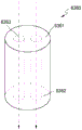
The heater 3130 may have a shape of a combination of a cylinder and a cone. The diameter of the heater 3130 may take a suitable size in the range of 2mm to 3 mm. Preferably, the heater 3130 may be made to have a diameter of 2.15mm, but is not limited thereto. In addition, the length of the heater 3130 may take an appropriate size in the range of 20mm to 30 mm. Preferably, the heater 3130 may be made to have a length of 19mm, but is not limited thereto. In addition, the end 131 of the heater 3130 may terminate at an acute angle, but is not limited thereto. In other words, the heater 3130 is not limited as long as it is in a shape that can be inserted into the inside of the cigarette. In addition, the heater 3130 may be heated only partially. For example, assuming that the length of the heater 3130 is 19mm, only a portion from the end 131 to 12mm of the heater 3130 may be heated, and the remaining portion of the heater 3130 may not be heated.
The heater 3130 may be a resistive heater. For example, a conductive track (track) is included in the heater 3130, and the heater 3130 may be heated as current flows in the conductive track.
For use stability, power of 3.2v,2.4a,8w specifications may be supplied to the heater 3130, but is not limited thereto. For example, in the case of supplying power to the heater 3130, the surface temperature of the heater 3130 may rise to 400 ℃ or higher. The surface temperature of the heater 3130 may rise to about 350 c within 15 seconds of the start of power to the heater 3130.
The holder 3100 may have an additional temperature detection sensor. Alternatively, the heater 3130 may function as a temperature detection sensor instead of the holder 3100. Alternatively, the holder 3100 may further include an additional temperature detection sensor while the heater 3130 of the holder 3100 functions as a temperature detection sensor. For the heater 3130 to function as a temperature detection sensor, the heater 3130 may include at least one conductive track for detecting heat generation and temperature. In addition, the heater 3130 may have a second conductive track for detecting temperature in addition to the first conductive track for generating heat.
For example, if the voltage of the second conductive track and the current flowing through the second conductive track are measured, the resistance R can be determined. At this time, the temperature T of the second conductive track may be determined by the following equation 1.
Mathematics 1
R=R0{1+α(T-T0)}
In the formula 1, R represents the current resistance value of the second conductive track, R 0 Indicating temperature T 0 The resistance value at (e.g., 0 ℃) and α represents the temperature coefficient of resistance of the second conductive track. The conductive material (e.g., metal) has an inherent temperature coefficient of resistance, so α may be predetermined based on the conductive material constituting the second conductive track. Thus, at the second conductive trackIn the case of determining the resistance R, the temperature T of the second conductive track can be calculated according to the above equation 1.
The heater 130 may be composed of at least one conductive track (first conductive track and second conductive track). For example, the heater 130 may be composed of two first conductive tracks and one or two second conductive tracks, but is not limited thereto.
The heater 3130 may be composed of at least one conductive track (a first conductive track and a second conductive track). For example, the heater 3130 may be composed of two first conductive tracks and one or two second conductive tracks, but is not limited thereto.
The conductive track comprises a resistive material. As an example, the conductive track is made of a metallic material. As another example, the conductive tracks may be made of conductive ceramic material, carbon, metal alloys or composite materials of ceramic material and metal.
In addition, the holder 3100 may have both a conductive track functioning as a temperature detection sensor and a temperature detection sensor.
The control unit 3120 controls the operation of the holder 3100 as a whole. Specifically, the control unit 3120 controls the operation of other structures in the holder 3100 in addition to the battery 3110 and the heater 3130. The control unit 3120 can also determine whether the holder 3100 is in an operable state by checking the state of each structure of the holder 3100.
The control portion 3120 includes at least one processor. A processor may be implemented as a plurality of logic gate arrays, or as a combination of a general-purpose microprocessor and a memory storing a program executable by the microprocessor. In addition, those skilled in the art will appreciate that the present embodiments may be implemented in other forms of hardware.
For example, the control unit 3120 can control the operation of the heater 3130. The control unit 3120 can control the amount of electricity supplied to the heater 3130 and the time of power supply so that the heater 3130 can be heated to a predetermined temperature or can be maintained at a suitable temperature. The control unit 3120 can confirm the state of the battery 3110 (e.g., the remaining capacity of the battery 3110), and can generate a warning signal when necessary.
The control unit 3120 can check whether the user has suctioned (puff) or not and the suction intensity, and can count the number of suctions. In addition, the control section 3120 may continuously confirm the time for which the holder 3100 operates. The control unit 3120 confirms whether or not the holder 3100 and the holder 3200, which will be described later, are in a coupled state, and can control the operation of the holder 3100 according to whether or not the holder 3100 and the holder 3200 are in a coupled state or a separated state.
On the other hand, the holder 3100 may include a general structure in addition to the battery 3110, the control 3120, and the heater 3130.
For example, the holder 3100 may include a display capable of outputting visual information or a motor for outputting tactile information. As an example, when the holder 3100 has a display, the control unit 3120 can transmit information on the state of the holder 3100 (for example, whether the holder can be used or not, etc.), information on the heater 3130 (for example, start of warm-up, warm-up completion, etc.), information on the battery 3110 (for example, remaining capacity of the battery 3110, usability, etc.), information on reset of the holder 3100 (for example, reset timing, reset completion, etc.), information on cleaning of the holder 3100 (for example, cleaning timing, cleaning need, cleaning completion, etc.), information on charging of the holder 3100 (for example, charging need, charging completion, etc.), information on suction (for example, suction number, suction end advance notice, etc.), or information on safety (for example, time of use, etc.), etc. to the user through the display. As another example, when the holder 3100 has a motor, the control unit 3120 generates a vibration signal by the motor and transmits the information to the user.
Additionally, the holder 3100 may include at least one input device (e.g., a button) and/or terminals coupled to the cradle 3200, thereby allowing a user to control the holder 3100. For example, the user may perform various functions using the input device of the holder 3100. By adjusting the number of times the user presses the input device (for example, 1 time, 2 times, etc.) or the time the input device is pressed (for example, 0.1 seconds, 0.2 seconds, etc.), a desired function among the plurality of functions of the holder 3100 can be performed. As the user activates the input device, the holder 3100 may perform a function of preheating the heater 3130, a function of adjusting the temperature of the heater 3130, a function of cleaning a space into which cigarettes are inserted, a function of checking whether the holder 3100 is in an operable state, a function of displaying the remaining amount (available power) of the battery 3110, a reset function of the holder 3100, and the like. However, the function of the holder 3100 is not limited to the above example.
For example, as described below, the holder 3100 may clean the space in which the cigarettes are inserted by controlling the heater 3130. For example, the holder 3100 may clean the space for cigarette insertion by heating the heater 3130 to a sufficiently high temperature. By sufficiently high temperature is meant here a temperature suitable for cleaning the space in which the cigarettes are inserted. For example, the holder 3100 may heat the heater 3130 to the highest temperature among a temperature range in which aerosol can occur in the inserted cigarette and a preheating temperature range of the heater 3130, but is not limited thereto.
In addition, the holder 3100 may maintain the temperature of the heater 3130 at a sufficiently high temperature for a prescribed period of time. Here, the prescribed period of time refers to a period of time sufficient to clean the space for cigarette insertion. For example, the holder 3100 may hold the temperature of the heated heater 3130 for an appropriate period of time among a period of time of 10 seconds to 10 minutes, but is not limited thereto. Preferably, the holder 3100 may maintain the temperature of the heated heater 3130 for an appropriate period of time selected in the range of 20 seconds to 1 minute. In addition, preferably, the holder 3100 may maintain the temperature of the heated heater 3130 for an appropriate period of time selected in the range of 20 seconds to 1 minute 30 seconds.
When the holder 3100 heats the heater 3130 to a sufficiently high temperature and maintains the temperature of the heated heater 3130 for a prescribed period of time, substances deposited on the surface of the heater 3130 and/or a space into which cigarettes are inserted volatilize, thereby producing a cleaning effect.
In addition, the holder 3100 may include a puff sensor, a temperature sensor, and/or a cigarette insertion sensor. For example, the suction detection sensor may be implemented by a general pressure sensor. Alternatively, the holder 3100 may detect suction through a resistance change of the conductive track included in the heater 3130 without having an additional suction detection sensor. Here, the conductive track includes a conductive track for heat generation and/or a conductive track for temperature detection. Alternatively, the holder 3100 may also include a suction detection sensor, independent of detecting suction with conductive tracks included in the heater 3130.
The smoke insertion detection sensor may be implemented by a general capacitive sensor or a resistive sensor. In addition, the holder 3100 may be configured to allow external air to be introduced/discharged even in a state where cigarettes are inserted.
Fig. 7A and 7B are diagrams showing an example of the retainer from a plurality of sides.
Fig. 7A is a diagram showing an example of the holder 3100 viewed from the first direction. As shown in fig. 7A, the holder 3100 may be made cylindrical, but is not limited thereto. The housing 3140 of the holder 3100 may be separated by a user's action, and cigarettes may be inserted from the end 3141 of the housing 3140. In addition, the holder 3100 may have buttons 3150 for a user to control the holder 3100 and a display 3160 for outputting an image (image).
Fig. 7B is a diagram showing an example of the holder 3100 viewed from the second direction. The holder 3100 may include terminals 3170 coupled to the carrier 3200. The terminal 3170 of the holder 3100 is coupled to the terminal 3260 of the cradle 3200, so that the battery 3110 of the holder 3100 can be charged by the electric power supplied from the battery 3210 of the cradle 3200. Further, the holder 3100 can be operated based on electric power supplied from the battery 3210 of the cradle 3200 by the terminal 3170 and the terminal 3260, and communication (transmission/reception of a signal) between the holder 3100 and the cradle 3200 can be also realized. For example, the terminal 170 may have 3 or 4 micro pins (pins), but is not limited thereto.
Fig. 8 is a structural view showing an example of the bracket.
Referring to fig. 8, the cradle 3200 includes a battery 3210 and a control portion 3220. In addition, the bracket 3200 has an inner space 3230 into which the holder 3100 is inserted. For example, the inner space 3230 may be formed at one side of the carrier 3200. Accordingly, the holder 3100 can be inserted and fixed in the carrier 3200 even if the carrier 3200 does not include an additional cover.
Only the components related to the present embodiment are shown in the bracket 3200 shown in fig. 8. Accordingly, it will be understood by those skilled in the art to which the present embodiment relates that the carrier 3200 may include other general-purpose constituent elements in addition to the components shown in fig. 8.
The battery 3210 supplies power required for the operation of the cradle 3200. In addition, the battery 3210 may supply electric power for charging the battery 3110 of the holder 3100. For example, when the holder 3100 is inserted into the holder 3200 and the terminal 3170 of the holder 3100 is coupled to the terminal 3260 of the holder 3200, the battery 3210 of the holder 3200 may supply power to the battery 3110 of the holder 3100.
In addition, when the holder 3100 is coupled to the bracket 3200, the battery 3210 can supply electric power necessary for the operation of the holder 3100. For example, when the terminal 3170 of the holder 3100 is coupled to the terminal 3260 of the cradle 3200, the holder 3100 can be operated by the electric power supplied from the battery 3210 of the cradle 3200, regardless of whether the battery 3110 of the holder 3100 is discharged.
For example, the battery 3210 may be a lithium ion battery, but is not limited thereto. In addition, the capacity of the battery 3210 may be larger than the capacity of the battery 3110, for example, the capacity of the battery 3210 may be 3000mAh or more, but the capacity of the battery 3210 is not limited to the above example.
The control unit 3220 controls the operation of the carriage 3200 as a whole. The control portion 3220 may control operations of all structures of the carrier 3200. The control unit 3220 determines whether the holder 3100 and the bracket 3200 are in the coupled state, and controls the operation of the bracket 3200 according to whether the bracket 3200 and the holder 3100 are in the coupled or separated state.
For example, when the holder 3100 is combined with the cradle 3200, the control section 3220 may charge the battery 3110 or heat the heater 3130 by supplying electric power of the battery 3210 to the holder 3100. Therefore, even when the remaining amount of the battery 3110 is small, the user can continuously smoke by combining the holder 3100 and the cradle 3200.
The control section 3220 includes at least one processor. A processor may be implemented as a plurality of logic gate arrays, or as a combination of a general-purpose microprocessor and a memory storing a program executable by the microprocessor. In addition, those skilled in the art will appreciate that the present embodiments may be implemented in other forms of hardware.
In one aspect, the cradle 3200 may have a general structure in addition to the battery 3210 and the control portion 3220. For example, the cradle 3200 may have a display that may output visual information. For example, when the cradle 3200 has a display, the control unit 3220 generates a signal for display on the display, and can transmit information about the battery 3220 (e.g., the remaining capacity of the battery 3220, usability, etc.), information about the reset of the cradle 3200 (e.g., the reset timing, the resetting, the completion of the resetting, etc.), information about the cleaning of the holder 3100 (e.g., the cleaning timing, the cleaning required, the cleaning being completed, etc.), information about the charging of the cradle 3200 (e.g., the charging required, the charging being completed, etc.), and the like to the user.
In addition, the carrier 3200 may include: at least one input device (e.g., a button) for a user to control the functions of the cradle 3200; a terminal 3260 associated with the holder 3100 and/or an interface (e.g., USB port, etc.) for charging the battery 3210.
For example, a user may perform various functions using the input device of the cradle 3200. By adjusting the number of times the user presses the input device or the time of pressing the input device, a desired function among the functions of the cradle 3200 can be performed. As the user activates the input device, the cradle 3200 may perform a function of preheating the heater 3130 of the holder 3100, a function of adjusting the temperature of the heater 3130 of the holder 3100, a function of cleaning a space within the holder 3100 into which cigarettes are inserted, a function of checking whether the cradle 3200 is in an operable state, a function of displaying the remaining amount (available power) of the battery 3210 of the cradle 3200, a reset function of the cradle 3200, and the like. However, the function of the holder 3200 is not limited to the above example.
Fig. 9A and 9B are diagrams showing an example of the bracket from a plurality of sides.
Fig. 9A is a diagram showing an example in which the holder 3200 is viewed from the first direction. A space 3230 into which the holder 3100 can be inserted is provided on one side surface of the bracket 3200. In addition, even if the holder 3200 does not have an additional fixing unit such as a cover, the holder 3100 can be inserted and fixed to the holder 3200. In addition, the cradle 3200 may have a button 3240 therein for a user to control the cradle 3200 and a display 3250 for outputting an image (image).
Fig. 9B is a diagram showing an example of the holder 3200 viewed from the second direction. The carrier 3200 may include terminals 3260 that are coupled with the inserted retainer 3100. The terminal 3260 is coupled to the terminal 3170 of the holder 3100, so that the battery 3110 of the holder 3100 can be charged by the electric power supplied from the battery 3210 of the cradle 3200. Further, the holder 3100 is operable by the power supplied from the battery 3210 of the cradle 3200 via the terminal 3170 and the terminal 3260, and transmission/reception of signals between the holder 3100 and the cradle 3200 is also possible. For example, terminal 3260 may have 4 micro pins (pins), but is not limited thereto.
As described with reference to fig. 6 to 9B, the holder 3100 may be inserted into the inner space 3230 of the bracket 3200. In addition, the holder 3100 may be completely inserted into the inside of the holder 3200, and may be tilted (tilt) in a state of being inserted into the holder 3200. An example in which the holder 3100 is inserted into the holder 3200 will be described below with reference to fig. 10 to 12B.
Fig. 10 is a view showing an example in which a holder is inserted in a bracket.
Referring to fig. 10, an example in which the holder 3100 is inserted into the holder 3200 is shown. Since there is a space 3230 for inserting the holder 3100 at one side of the carrier 3200, the inserted holder 3100 is not exposed to the outside from the other side of the carrier 3200. Accordingly, the bracket 3200 may not have other structures (e.g., a cover) that prevent the holder 3100 from being exposed to the outside.
The bracket 3200 may have at least one coupling member 3271, 3272 for improving coupling strength with the holder 3100. In addition, the holder 3100 also has at least one coupling member 3181. Here, the coupling members 3181, 3271, 3272 may be magnets, but are not limited thereto. In fig. 10, for convenience of explanation, the holder 3100 is shown to have one coupling member 3181, and the bracket 3200 has two coupling members 3271, 3272, but the number of coupling members 3181, 3271, 3272 is not limited thereto.
The holder 3100 may have coupling members 3181 in a first position, and the carrier 3200 may have coupling members 3271, 3272 in a second position and a third position, respectively. At this time, the first position and the third position are located at opposite positions in a case where the holder 3100 is inserted in the bracket 3200.
Since the holder 3100 and the bracket 3200 have the coupling members 3181, 3271, 3272, even if the holder 3100 is inserted into one side surface of the bracket 3200, the holder 3100 and the bracket 3200 can be coupled more firmly. In other words, the holder 3100 and the bracket 3200 have coupling members 3181, 3271, 3272 in addition to the terminals 3170, 3260, whereby the holder 3100 and the bracket 3200 can be coupled more firmly. Accordingly, even if the carrier 3200 does not have an additional structure (e.g., a cover), the inserted holder 3100 may not be easily separated from the carrier 3200.
When it is determined that the holder 3100 is completely inserted into the holder 3200 via the terminals 3170 and 3260 and/or the coupling members 3181, 3271 and 3272, the control unit 3220 can charge the battery 3110 of the holder 3100 by using the electric power of the battery 3210.
Fig. 11 is a view showing an example of tilting in a state in which the holder is inserted into the bracket.
Referring to fig. 11, the holder 3100 is tilted from the inside of the cradle 3200. Here, the roll means that the holder 3100 is inclined at a predetermined angle in a state of being inserted into the holder 3200.
As shown in fig. 10, in a case where the holder 3100 is completely inserted on the holder 3200, a user cannot smoke. In other words, when the holder 3100 is fully inserted on the cradle 3200, cigarettes cannot be inserted into the holder 3100. Therefore, in a state in which the holder 3100 has been completely inserted on the holder 3200, a user cannot smoke.
As shown in fig. 11, when the holder 3100 is tilted, the tip 3141 of the holder 3100 is exposed to the outside. The user may then insert the cigarette into the end 3141, thereby enabling inhalation of the aerosol (smoking) produced. The roll angle θ should ensure that the angle is large enough to avoid breakage or damage to the cigarette when inserted into the end 3141 of the holder 3100. For example, the holder 3100 may be tilted at a minimum angle or a greater angle than the minimum angle at which the cigarette insertion hole provided at the tip 3141 is entirely exposed to the outside. For example, the range of the roll angle θ may be greater than 0 ° and 180 ° or less, and preferably, may be 5 ° or more and 90 ° or less. More preferably, the roll angle θ may range from 5 ° to 20 ° inclusive, from 5 ° to 30 ° inclusive, from 5 ° to 40 ° inclusive, from 5 ° to 50 ° inclusive, or from 5 ° to 60 ° inclusive. Most preferably, the roll angle θ may be 10 °.
In addition, even if the holder 3100 is tilted, the terminal 3170 of the holder 3100 is coupled to the terminal 3260 of the bracket 3200. Accordingly, the heater 3130 of the holder 3100 may be heated by the power supplied from the battery 3210 of the cradle 3200. Therefore, even in the case where the remaining amount of the battery 3110 of the holder 3100 is small or none, the holder 3100 can generate aerosol using the battery 3210 of the cradle 3200.
In fig. 11, an example is shown in which the holder 3100 includes one coupling member 3182, and the bracket 3200 includes two coupling members 3273, 3274. For example, the positions of the coupling members 3182, 3273, 3274 are as described with reference to fig. 10. Assuming that the coupling members 3182, 3273, 3274 are magnets, the magnetic field strength of the coupling member 3274 may be greater than the magnetic field strength of the coupling member 3273. Therefore, even if the holder 3100 is tilted, the holder 3100 is not completely separated from the bracket 3200 due to the coupling member 3182 and the coupling member 3274.
When it is determined that the holder 3100 is tilted by the terminals 3170, 3260 and/or the coupling members 3182, 3273, 3274, the control unit 3220 may heat the heater 3130 of the holder 3100 or charge the battery 3110 by using the electric power of the battery 3210.
Fig. 12A to 12B are diagrams showing examples of the holder insertion bracket.
Fig. 12A shows an example in which the holder 3100 is completely inserted on the bracket 3100. The interior space 3230 of the carrier 3200 is made to be sufficient to ensure minimal user contact with the holder 3100 fully inserted on the carrier 3200. When the holder 3100 is fully inserted into the cradle 3200, the control section 3220 causes the battery 3210 to supply power to the holder 3100 so that the battery 3110 of the holder 3100 can be charged.
Fig. 12B shows an example of the retainer 3100 being tilted in a state of being inserted in the bracket 3200. When the holder 3100 is tilted, the control unit 3220 causes the battery 3210 to supply power to the holder 3100 so that the battery 3110 of the holder 3100 can be charged or the heater 3130 of the holder 3100 can be heated.
Fig. 13 is a flowchart for explaining an example of the operation of the holder and the bracket.
The method of generating an aerosol shown in fig. 13 includes steps of processing in time series in the holder 3100 shown in fig. 6 or the cradle 3200 shown in fig. 8. Therefore, in the following, even though omitted, the above description about the holder 3100 shown in fig. 6 or the cradle 3200 shown in fig. 8 can be applied to the method of fig. 13.
In step 3810, it is determined whether the holder 3100 is inserted in the holder 3200. For example, the control unit 3120 may determine whether the holder 3100 is inserted into the bracket 3200 based on whether the terminals 3170, 3260 of the holder 3100 and the bracket 3200 are connected to each other and/or whether the coupling members 3181, 3271, 3272 are operated.
If the holder 3100 has been inserted into the holder 3200, step 3820 is performed, and if the holder 3100 has been separated from the holder 3200, step 3830 is performed.
In step 3820, the cradle 3200 determines whether the holder 3100 is tilted. For example, the control unit 3220 may determine whether the holder 3100 is tilted according to whether the terminals 3170, 3260 of the holder 3100 and the bracket 3200 are connected to each other and/or whether the coupling members 3182, 3273, 3274 are operated.
In step 3820, the case where the bracket 3200 determines whether the holder 3100 is tilted or not has been described, but the present invention is not limited thereto. In other words, the control unit 3120 of the holder 3100 may determine whether the holder 3100 is tilted.
If the holder 3100 is tilted, step 3840 is performed, and if the holder 3100 is not tilted (i.e., if the holder 3100 is fully inserted into the cradle 3200), step 3870 is performed.
In step 3830, the holder 3100 determines whether the use condition of the holder 3100 is satisfied. For example, the control unit 3120 determines whether the usage conditions have been satisfied by confirming whether the remaining amount of the battery 3110 and other structures of the holder 3100 can operate normally.
If the use condition of the holder 3100 is satisfied, step 3840 is performed, otherwise, the process ends.
In step 3840, the holder 3100 prompts the user to be in a usable state. For example, the control unit 3120 may output an image (image) indicating that the device is in a usable state to the display of the holder 3100, and may control the motor of the holder 3100 to generate a vibration signal.
In step 3850, the heater 3130 is heated. As an example, when the holder 3100 is separated from the bracket 3200, the heater 3130 may be heated by the electric power of the battery 3110 of the holder 3100. As another example, when the holder 3100 is tilted, the heater 3130 may be heated by the electric power of the battery 3210 of the cradle 3200.
The control unit 3120 of the holder 3100 or the control unit 3220 of the cradle 3200 can check the temperature of the heater 3130 in real time, and adjust the amount of power supplied to the heater 3130 and the power supply time to the heater 3130. For example, the control portions 3120, 3220 may confirm the temperature of the heater 3130 in real time by a temperature detection sensor in the holder 3100 or a conductive track of the heater 3130.
In step 3860, the holder 3100 performs an aerosol generating mechanism (mechanism). For example, the control portions 3120, 3220 regulate the amount of power supplied to the heater 3130 or interrupt power supply to the heater 3130 by confirming the temperature of the heater 3130 that varies with user's suction. The control units 3120 and 3220 may count the number of times the user sucks, and may output information indicating that the cleaning holder is required when the number of times (for example, 1500 times) of suction is reached.
In step 3870, the cradle 3200 performs charging of the holder 3100. For example, the control unit 3220 may charge the holder 3100 by supplying electric power of the battery 3210 of the cradle 3200 to the battery 3110 of the holder 3100.
On the other hand, the control units 3120 and 3220 may stop the operation of the holder 3100 according to the number of times of suction by the user or the operation time of the holder 3100. An example in which the control units 3120, 3220 stop the operation of the holder 3100 will be described below with reference to fig. 14.
Fig. 14 is a flowchart for explaining another example of the retainer operation.
The method of generating an aerosol shown in fig. 14 includes steps of processing in time series in the holder 3100 shown in fig. 6 and the cradle 3200 shown in fig. 8. Therefore, in the following, even though omitted, the above description about the holder 3100 shown in fig. 6 or the cradle 3200 shown in fig. 8 can be applied to the method of fig. 14.
In step 3910, the control units 3120 and 3220 determine whether or not the user has suctioned. For example, the control units 3120, 3220 may determine whether or not the user has suctioned by a suction detection sensor included in the holder 3100. Alternatively, the control parts 3120, 3220 may determine whether the user draws or not using the resistance change of the conductive track included in the heater 3130. Here, the conductive track includes a conductive track for heat generation and/or a conductive track for temperature detection. Alternatively, the control parts 3120, 3220 may determine whether the user is sucking or not using the resistance change of the conductive track included in the heater 3130 and the sucking detection sensor.
In step 3920, an aerosol is generated by aspiration of a user. The control units 3120 and 3220 can adjust the power supplied to the heater 3130 according to the suction of the user and the temperature of the heater 3130, as described with reference to fig. 13. The control units 3120 and 3220 count the number of times the user sucks.
In step 3930, the control units 3120, 3220 determine whether the number of times the user has sucked is equal to or greater than the suction limit number. For example, assuming that the number of suction restrictions is set to 14, the control sections 3120, 3220 determine whether the counted number of suction is 14 or more. However, the number of times of suction restriction is not limited to 14. For example, the number of suction restrictions may be set to an appropriate number of 10 times or 16 times.
On the other hand, in a case where the number of times of suction by the user is close to the suction limit number (for example, in a case where the number of times of suction by the user is 12), the control units 3120, 3220 may output a warning signal through the display or the vibration motor.
If the number of puffs of the user is above the number of puffs limit, step 3950 is performed, and if the number of puffs of the user is less than the number of puffs limit, step 3940 is performed.
In step 3940, the control units 3120 and 3220 determine whether the operation time of the holder 3100 is equal to or longer than the operation limit time. Here, the operation time of the holder 3100 refers to the time accumulated until the present at the point of time when the holder starts to operate. For example, assuming that the operation limiting time is set to 10 minutes, the control units 3120, 3220 determine whether the holder 3100 has been operated for 10 minutes or more.
On the other hand, when the operation time of the holder 3100 is close to the operation limit time (for example, when the holder 3100 is operated for 8 minutes), the control units 3120, 3220 may output a warning signal via a display or a vibration motor.
If the holder 3100 is operated for more than the operation limit time, step 3950 is performed, and if the operation time of the holder 3100 is less than the operation limit time, step 3920 is performed.
In step 3950, the control units 3120 and 3220 forcibly end the operation of the holder. In other words, the control portion 3120, 3220 terminates the aerosol-generating mechanism of the holder. For example, the control units 3120 and 3220 may forcibly terminate the operation of the holder by cutting off the power supply to the heater 3130.
Fig. 15 is a flowchart for explaining an example of the operation of the carriage.
The flowchart shown in fig. 15 includes steps that are processed in time series in the cradle 3200 shown in fig. 8. Therefore, in the following, even though omitted, the above description of the cradle 3200 shown in fig. 8 can be applied to the flowchart of fig. 15.
Although not shown in fig. 15, the operation of the holder 3200 described below may be performed regardless of whether the holder 3100 is inserted into the holder 3200.
In step 4010, the control unit 3220 of the cradle 3200 determines whether or not the button 3240 is pressed. If the button 3240 is pressed, step 4020 is performed, and if the button 3240 is not pressed, step 4030 is performed.
In step 4020, the cradle 3200 displays the status of the battery. For example, the control portion 3220 may output information about the current state (e.g., a margin, etc.) of the battery 3210 to the display 3250.
In step 4030, the control unit 3220 of the cradle 3200 determines whether or not a cable is connected to the cradle 3200. For example, the control unit 3220 determines whether or not a cable is connected to an interface (for example, a USB port) of the cradle 3200. If a cable is connected to the cradle 3200, step 4040 is performed, otherwise, the process is ended.
In step 4040, the cradle 3200 performs a charging operation. For example, the cradle 3200 charges the battery 3210 with electric power supplied through a connected cable.
As described with reference to fig. 6, cigarettes may be inserted in the holder 3100. The cigarette contains an aerosol-generating substance that is generated by a heated heater 3130.
Hereinafter, with reference to fig. 16 to 18F, a cigarette capable of being inserted into the holder 3100 is exemplified.
Fig. 16 is a view showing an example of the cigarette insertion holder.
Referring to fig. 16, a cigarette 3300 may be inserted into the holder 3100 through the end 3141 of the housing 3140. When the cigarette 3300 is inserted, the heater 3130 may be located inside the cigarette 3300. Accordingly, the heated heater 3130 heats the aerosol-generating material of the cigarette 3300, thereby generating aerosol.
The first portion 3310 may be integrally inserted into the interior of the holder 3100 while the second portion 3320 is exposed to the outside. Alternatively, only a part of the first portion 3310 may be inserted into the holder 3100, or a part of the first portion 3310 and the second portion 3320 may be inserted.
The user may grasp the second portion 3320 in the mouth to inhale the aerosol. At this time, the aerosol is generated by the external air through the first portion 3310, and the generated aerosol is transferred to the user's mouth through the second portion.
The external air may flow in (5120) via at least one air passage formed in the holder 3100. For example, the opening and closing of the air passage formed in the holder 3100 and/or the size of the air passage may be adjusted by a user. Thus, the amount of atomization, smoking sensation, etc. can be adjusted by the user.
Alternatively, the external air may flow into 5110 via at least one hole (hole) formed in the surface of the cigarette 3300.
Fig. 17A and 17B are block diagrams illustrating an example of a cigarette.
Referring to fig. 17A and 17B, a cigarette 3300 includes a tobacco rod 3310, a first filter segment 3321, a cooling structure 3322, and a second filter segment 3323. The first portion 3310 described with reference to fig. 16 includes a tobacco rod 3310 and the second portion 3320 includes a first filter segment 3321, a cooling structure 3322, and a second filter segment 3323.
Referring to fig. 17A, cigarettes 3300 may be packaged with a total of 5 wrappers (3341, 3342, 3343, 3344, 3345). In one aspect, referring to fig. 17B, cigarette 3300 may be wrapped with a total of 6 wrappers (3341, 3342, 3343, 3344, 3346, 3347). The tobacco rod 3310 is wrapped in a first wrapper 3341 and the first filter segment 3321 is wrapped in a second wrapper 3342. In addition, the cooling structure 3322 is wrapped with a third wrapper 3343 and the second filter segment 3323 is wrapped with a fourth wrapper 3344.
The fifth wrapper 3345 of fig. 17A may surround the outer periphery of the first wrapper 3341, the second wrapper 3342, the third wrapper 3343, and the fourth wrapper 3344. In other words, the entire cigarette 3300 may be double wrapped by the fifth wrapper 3345.
In one aspect, the sixth wrapper 3346 of fig. 17B may surround the first wrapper 3341, the second wrapper 3342, and the third wrapper 3343. In other words, the tobacco rod 3310, first filter segment 3321 and cooling structure 3322 of cigarette 3300 may be double wrapped with the sixth wrapper. In addition, the seventh wrapper 3347 of fig. 17B may surround at least a portion of the third wrapper 3343 and the periphery of the fourth wrapper 3344. In other words, at least a portion of the cooling structure 3322 and the second filter segment 3323 of the cigarette 3300 may be secondarily wrapped with the seventh wrapper 3347.
The first wrapper 3341 and the second wrapper 3342 may be made of a common filter roll. For example, the first wrapping paper 3341 and the second wrapping paper 3342 may be porous roll paper or nonporous roll paper. In addition, the first and second wrapping papers 3341 and 3342 may be made of oil-resistant paper and aluminum and paper wrapping papers.
The third wrapper 3343 may be made of hard roll paper. For example, the basis weight of the third wrapper 3343 may be 90g/m 2 But is not limited thereto.
The fourth wrapper 3344 may be made of oil-resistant hard roll paper. For example, the fourth wrapper 3344 may have a basis weight of 92g/m 2 The thickness may be 125 μm, but is not limited thereto.
The fifth wrapper 3345, the sixth wrapper 3346, and the seventh wrapper 3347 may be made of sterilized paper (MFW). Here, the sterilized paper Means (MFW) paper which has been specially manufactured to enhance tensile strength, water resistance, smoothness, etc. as compared with plain paper. For example, the basis weight of the fifth wrapper 3345, sixth wrapper 3346 and seventh wrapper 3347 may be 60g/m 2 The thickness may be 67 μm, but is not limited thereto. In addition, the tensile strength of the fifth wrapping paper 3345, the sixth wrapping paper 3346, and the seventh wrapping paper 3347 may be in the range of 8kgf/15mm to 11kgf/15mm on a dry basis and 1.0kgf/15mm on a wet basis, but is not limited thereto.
The fifth wrapper 3345, the sixth wrapper 3346 and the seventh wrapper 3347 may include a prescribed substance. Here, the predetermined substance may be silicon, but is not limited thereto. For example, silicon has characteristics such as heat resistance with little change in temperature, oxidation resistance without being oxidized, resistance to various drugs, hydrophobicity to water, or electrical insulation. However, even if not silicon, the fifth wrapping paper 3345, the sixth wrapping paper 3346, and the seventh wrapping paper 3347 may be applied (or coated) without limitation as long as they have the above-described characteristics.
The fifth wrapping paper 3345, the sixth wrapping paper 3346, and the seventh wrapping paper 3347 can prevent the burning phenomenon of the cigarettes 3300. For example, when the tobacco rod 3310 is heated by the heater 3130, there is a possibility that the cigarette 3300 is burned. Specifically, when the temperature rises above the ignition point of any of the substances included in the tobacco rod 3310, the cigarette 3300 may be burned. Even in this case, the fifth wrapping paper 3345, the sixth wrapping paper 3346, and the seventh wrapping paper 3347 contain a nonflammable substance, so that the phenomenon that the cigarettes 3300 are burned can be prevented.
In addition, the fifth wrapping 3345, sixth wrapping 3346, and seventh wrapping 3347 may prevent the holder 3100 from being contaminated by substances generated in the cigarettes 3300. Upon inhalation by the user, liquid material is produced within the cigarette 3300. For example, aerosols generated in the cigarette 3300 are cooled by outside air, so that liquid substances (e.g., moisture, etc.) may be generated. The tobacco rod 3310 and/or the first filter segment 3321 are wrapped with the fifth wrapping paper 3345, the sixth wrapping paper 3346, and the seventh wrapping paper 3347, so that the liquid substances generated in the cigarettes 3300 can be prevented from flowing out of the cigarettes 3300. Therefore, the housing 3140 of the holder 3100 and the like can be prevented from being contaminated by the liquid substances generated in the cigarettes 3300.
The cigarette 3300 may have a diameter in the range of 5mm to 9mm and a length of about 48mm, but is not limited thereto. Preferably, the diameter of the cigarette 3300 may be 7.2mm, but is not limited thereto. In addition, the tobacco rod 3310 may be about 12mm in length, the first filter segment 3321 may be about 10mm in length, the cooling structure 3322 may be about 14mm in length, and the second filter segment 3323 may be about 12mm in length, but is not limited thereto.
The structure of the cigarette 3300 shown in fig. 17A and 17B is merely an example, and a partial structure may be omitted. For example, one or more of the first filter segment 3321, the cooling structure 3322, and the second filter segment 3323 in the cigarette 3300 may be omitted.
The tobacco rod 3310 contains aerosol-generating substances. For example, the aerosol-generating substance may comprise at least one of glycerol, propylene glycol, ethylene glycol, dipropylene glycol, diethylene glycol, triethylene glycol, tetraethylene glycol, and oleyl alcohol.
In addition, the tobacco rod 3310 may include other additives such as flavoring agents, humectants, and/or organic acids (organic acids). For example, the flavoring agent may include licorice, sucrose, fructose syrup, ISO sweetener (isosweet), cocoa, lavender, cinnamon, cardamon, celery, fenugreek, bitter skin, sandalwood, bergamot, geranium, honey essence, rose oil, vanilla, lemon oil, orange oil, peppermint oil, cinnamon, caraway, coriander brandy (cognac), jasmine, chamomile, menthol, cinnamon, ylang, sage, spearmint, ginger, caraway, or coffee, among others. In addition, the humectant may include glycerin or propylene glycol, and the like.
As an example, the tobacco rod 3310 may be filled with tobacco. Here, the tobacco leaf may be produced by cutting a tobacco sheet.
In order to fill the wide tobacco sheet into the tobacco rod 3310 having a narrow space, a special process may be required to enable the tobacco sheet to be easily folded. Therefore, filling the tobacco rod 3310 with tobacco leaves is easier and the productivity and efficiency of the process of producing the tobacco rod 3310 is higher than filling the tobacco rod 3310 with tobacco sheets.
As another example, the tobacco rod 3310 may be filled with a plurality of tobacco filaments obtained by cutting a tobacco sheet. For example, the tobacco rod 3310 may be composed of multiple tobacco filaments in the same direction (parallel) or randomly. In particular, the tobacco rod 3310 is formed by combining a plurality of tobacco filaments and may form a plurality of longitudinal channels for the insertion of the heater 3130 or the passage of aerosol. At this time, the longitudinal channels may be uniform or non-uniform depending on the size and arrangement of the tobacco filaments.
For example, tobacco shreds may be produced by the following process. First, a tobacco raw material is pulverized to prepare a slurry of a mixed aerosol-generating substance (for example, glycerin, propylene glycol, etc.), an essence, a binder (for example, guan Huadou gum, xanthan gum, carboxymethyl cellulose (Carboxymethyl cellulose, CMC), etc.), water, etc., and a tobacco sheet is formed from the slurry. In making the slurry, natural pulp or cellulose may be added to improve the physical properties of the tobacco shreds, and more than one binder may be used in combination. And, after drying the sheet, tobacco shreds are produced by cutting or fine-cutting the dried tobacco sheet.
The tobacco material may be tobacco scraps, tobacco stems, tobacco dust produced in tobacco treatment. In addition, the tobacco sheet may also contain other additives, such as wood cellulose fibers.
From 5% to 40% aerosol-generating material may be added to the slurry and from 2% to 35% aerosol-generating material may remain in the finished tobacco filament. Preferably, 10% to 25% of the aerosol-generating substance may remain in the finished tobacco rod.
In addition, a flavoring such as menthol or a humectant may be sprayed and added to the center of the tobacco rod 3310 before the process of wrapping the tobacco rod 3310 with the first wrapper 3341 is performed.
The tobacco filaments may be formed into a rectangular parallelepiped shape having a transverse length of 0.5mm to 2mm, a longitudinal length of 5mm to 50mm, and a thickness (height) of 0.1mm to 0.3mm, but are not limited thereto. Preferably, the tobacco filaments can be made to have a transverse length of 0.9mm and a longitudinal length 20mm, a rectangular parallelepiped shape with a thickness (height) of 0.2 mm. In addition, it can be made such that the basis weight of one tobacco filament is 100g/m 2 To 250g/m 2 But is not limited thereto. Preferably, the tobacco filaments can be made to have a basis weight of 180g/m 2 。
The tobacco rod 3310 filled with tobacco filaments may generate more aerosol than if the tobacco rod 3310 were filled with tobacco sheets. Given that the same space is filled, tobacco filaments can ensure a wider surface area than tobacco sheets. The broad surface area means that the aerosol-generating substance has a greater chance of coming into contact with the outside air. Therefore, the tobacco rod 3310 can generate more aerosol than the tobacco sheet filling.
In addition, when the cigarette 3300 is separated from the holder 3100, separation can be performed more easily in the case where the tobacco rod 3310 is filled with tobacco shreds than in the case where the tobacco rod 3310 is filled with tobacco sheets. In other words, in the case where the tobacco rod 3310 is filled with tobacco filaments, it can be more easily separated from the holder 3100 than in the case of being filled with tobacco sheets.
The first filter segment 3321 may be a cellulose acetate filter. For example, the first filter segment 3321 may be a hollow tubular structure with a hollow interior. The length of the first filter segment 3321 may take a suitable length in the range of 4mm to 30mm, but is not limited thereto. Preferably, the length of the first filter segment 3321 may be 10mm, but is not limited thereto.
The hollow included in the first filter segment 3321 may take a suitable diameter in the range of 3mm to 4.5mm, but is not limited thereto.
The hardness of first filter segment 3321 may be adjusted by adjusting the amount of plasticizer during manufacture of first filter segment 3321.
To prevent the size of the first filter segment 3321 from decreasing over time, the outer periphery of the first filter segment 3321 may be made to be wrapped with a wrapper. Thus, the first filter segment 3321 can be easily combined with other structures (e.g., other filter segments).
In addition, the first filter segment 3321 may be manufactured by inserting a film or a tubular structure of the same or different materials into the interior (e.g., hollow).
The first filter segment 3321 may be made from cellulose acetate. Thereby, the phenomenon that the internal substance of the tobacco rod 3310 is pushed back when the heater 3130 is inserted can be prevented, and the cooling effect of the aerosol can occur.
The cooling structure 3322 cools the aerosol generated by the heater 3130 heating the tobacco rod 3310. Thus, the user can inhale the aerosol cooled to an appropriate temperature.
The length or diameter of the cooling structure 3322 may be determined in various sizes according to the shape of the cigarette 3300. For example, the length of the cooling structure 3322 may be suitably employed in the range of 7mm to 20 mm. Preferably, the length of the cooling structure 3322 may be about 14mm, but is not limited thereto.
The cooling structure 3322 may be made of pure polylactic acid or may be made of a combination of other degradable polymers and polylactic acid. For example, the cooling structure 3322 may be made by extrusion or weaving of fibers. To increase the surface area per unit area (i.e., the surface area in contact with the aerosol), the cooling structure 3322 may be formed in a variety of shapes.
For example, the cooling structure 3322 may be made by weaving fibers made of polylactic acid. At this time, essence may be coated on the fibers made of polylactic acid. Alternatively, the cooling structure 3322 may be manufactured using both the separate fibers coated with the essence and the fibers made of polylactic acid. The polylactic acid fiber may be dyed to a predetermined color, and the dyed fiber may be used to manufacture the cooling structure 3322.
Various examples of the cooling structure 3322 will be described with reference to fig. 18A to 18F.
The second filter segment 3323 may also be a cellulose acetate filter. For example, the second filter segment 3323 may be made as an embedded filter, but is not limited thereto. The length of the second filter segment 3323 may suitably be in the range 4mm to 20 mm. For example, the length of the second filter segment 3323 may be about 12mm, but is not limited thereto.
During the manufacture of the second filter segment 3323, a flavor can be generated by spraying a flavor onto the second filter segment 3323. Alternatively, individual fibers coated with a flavor may also be inserted into the interior of the second filter segment 3323. The aerosol generated in the tobacco rod 3310 is cooled as it passes through the cooling structure 3322 and the cooled aerosol is delivered to the user through the second filter segment 3323. Thus, when the flavoring element is added to the second filter segment 3323, an effect of enhancing the durability of the flavor delivered to the user may be produced.
In addition, the second filter segment 3323 may comprise at least one capsule 3324. Here, the capsule 3324 may have a structure in which the perfume-containing contents are surrounded by a coating. For example, the capsule 3324 may have a spherical or cylindrical shape.
The capsule 3324 can be prepared from agar (agar), pectin, sodium alginate, carrageenan, gelatin or Guan Huadou gel. As a material for forming the capsule 3324 film, a curing aid may be further used. Here, as the gel auxiliary agent, for example, calcium chloride or the like can be used. Further, as a material for forming the capsule 3324 film, a plasticizer may be further used. Here, glycerin and/or sorbitol may be used as the plasticizer. Further, as a material for forming the capsule 3324 film, a coloring material may be further used.
For example, peppermint oil, essential oils of plants, and the like can be used as the flavor contained in the content liquid of the capsule. As a solvent for the flavor contained in the content liquid, for example, medium Chain Triglyceride (MCT) can be used. The content liquid may contain other additives such as pigment, emulsifier, and thickener.
Fig. 18A to 18F are diagrams showing examples of the cooling structure of the cigarette.
For example, the cooling structures shown in fig. 18A to 18F may be made using fibers produced from pure polylactic acid (PLA).
For example, when a film (sheet) of a cooling structure is produced by filling the film (sheet), the film (sheet) may be crushed by an external impact. In this case, the effect of the cooling structure to cool the aerosol is reduced.
As another example, in the case of manufacturing a cooling structure by extrusion molding or the like, as the number of steps such as cutting the structure increases, the efficiency of the steps decreases. In addition, there are limitations in manufacturing the cooling structure in various shapes.
The cooling structure of one embodiment is made of polylactic acid fibers (e.g., woven), so that the risk of deformation or loss of action of the cooling structure due to external impact can be reduced. In addition, by changing the combination mode of the fiber bundles, a cooling structure having various shapes can be manufactured.
In addition, by using the cooling fiber to make a cooling structure, the surface area in contact with the aerosol is increased. Therefore, the aerosol cooling effect of the cooling structure can be further improved.
Referring to fig. 18A, the cooling structure 6310 may be formed in a cylindrical shape, and may be formed such that at least one air passage 6311 is formed in a cross section of the cooling structure 6310.
Referring to fig. 18B, the cooling structure 6320 may be formed as a structure in which a plurality of filaments are interlaced. At this time, the aerosol may flow between the filaments, and a vortex may be formed according to the shape of the cooling structure 6320. The resulting vortex increases the contact area of the aerosol in the cooling structure 6320, increasing the time the aerosol stays within the cooling structure 6320. Thus, the heated aerosol can be effectively cooled.
Referring to fig. 18C, the cooling structure 6330 may be formed in a shape in which a plurality of bundles 6331 are gathered.
Referring to fig. 18D, the cooling structure 6340 may be filled with particles made of polylactic acid, tobacco leaf, or charcoal, respectively. Alternatively, the particles may be made from a blend of polylactic acid, tobacco and char. On the other hand, the particles may contain elements that enhance the cooling effect of the aerosol in addition to polylactic acid, tobacco leaves, and/or charcoal.
Referring to fig. 18E, the cooling structure 6350 may include a first end face 6351 and a second end face 6352.
The first end face 6351, intersecting the first filter segment 3321 boundary, may have apertures into which aerosol flows. The second end face 6352, intersecting the second filter segment 3323 boundary, may have apertures capable of discharging aerosol. For example, the first end face 6351 and the second end face 6352 may have a single aperture having the same diameter, but the diameter and the number of apertures that the first end face 6351 and the second end face 6352 have are not limited thereto.
Also, the cooling structure 6350 may have a third end face 6353 between the first end face 6351 and the second end face 6352, the third end face 6353 having a plurality of apertures. For example, the diameter of the plurality of apertures of the third end face 6353 may be smaller than the diameters of the apertures of the first end face 6351 and the second end face 6352. The third end surface 6353 may have a larger number of pores than the first end surface 6351 and the second end surface 6352.
Referring to fig. 18F, the cooling structure 6360 may include a first end face 6361 intersecting the boundary of the first filter segment 3321 and a second end face 6362 intersecting the boundary of the second filter segment 3323. In addition, the cooling structure 6360 may include more than one tubular member 6363. For example, the tubular member 6363 can pass through the first end face 6361 and the second end face 6362. In addition, the tubular member 6363 may be packaged by a microporous packaging material, and by a filler material capable of improving the cooling effect of the aerosol (for example, refer to fig. 18
The particles described in D).
As described above, the holder is capable of heating the cigarette to generate an aerosol. In addition, the holder may generate an aerosol in a state of being used alone, or may generate an aerosol in a state of being inserted into the bracket and being tilted. In particular, in the case of the holder being tilted, the heater may be heated by the electric power of the battery of the bracket.
In one aspect, the above-described method may be a program executable in a computer, and may be implemented in a general-purpose digital computer that executes the program using a computer-readable storage medium. Moreover, the data structures used in the method may be stored in a computer-readable storage medium by various means. The computer-readable storage medium includes magnetic storage media (e.g., read-only memory (ROM), random-access memory (RAM), USB, floppy disks, hard disks), and optical storage media (e.g., compact Disks (CD) -ROMs, high-density Digital Video Disks (DVDs), etc.).
It will be appreciated by those of ordinary skill in the art to which the present embodiment relates that variations may be implemented without departing from the essential characteristics described above. Accordingly, the disclosed methods should not be considered in a limiting sense, but rather in an illustrative sense. The scope of the invention is defined not by the foregoing invention but by the appended claims, and all differences within the equivalent scope will be construed as being included in the present invention.
Claims (15)
1. An aerosol-generating device, wherein,
comprising the following steps:
a power supply unit having a first battery and a second battery,
a sensor for detecting inhalation by a user,
Control part
A heater;
the control unit controls the power supply unit to operate in either a first mode in which power is supplied to the heater by the first battery or a second mode in which power is supplied to the heater by the second battery,
when inhalation is detected, the control section controls the power supply section to operate in accordance with a first mode,
the control section controls the power supply section to supply the heater with power larger than that supplied in the second mode in the first mode.
2. An aerosol-generating device according to claim 1, wherein,
the first mode is a mode for increasing the temperature of the heater,
the second mode is a mode for maintaining a temperature of the heater.
3. An aerosol-generating device according to claim 1, wherein,
the first battery includes a lithium ion capacitor.
4. An aerosol-generating device according to claim 1, wherein,
the second battery comprises one of a lithium ion battery, a lithium iron phosphate battery, a lithium titanate battery and a lithium polymer battery.
5. An aerosol-generating device according to claim 1, wherein,
The aerosol-generating device further comprises:
a sensor for detecting the temperature of the heater;
when the inhalation is detected, the control section controls the power supply section to operate as follows: the operation is performed in the first mode when the temperature of the heater is equal to or lower than a first temperature, and in the second mode when the temperature of the heater is equal to or higher than the first temperature.
6. An aerosol-generating device according to claim 1, wherein,
the control part is provided with a control part,
the power supply unit is controlled to operate in the first mode while the temperature of the heater is rising to a critical temperature,
and controlling the power supply unit to operate in the second mode when the temperature of the heater is equal to or higher than the critical temperature.
7. An aerosol-generating device according to claim 1, wherein,
the control part is provided with a control part,
controlling the power supply part to operate according to the first mode during a first time,
and controlling the power supply part to operate according to the second mode after the first time passes.
8. An aerosol-generating device according to claim 1, wherein,
The aerosol-generating device further comprises a memory for storing a condition for switching from the first mode to the second mode,
the condition includes a temperature of the heater and a time during which the power supply portion operates in the first mode.
9. A control method of an aerosol-generating device, wherein,
the method comprises the following steps:
when inhalation by a user is detected, controlling the power supply part to operate in a first mode of supplying power to the heater by using a first battery when the temperature of the heater is lower than a first temperature, and
the power supply unit is controlled to operate in either one of the first mode and a second mode in which the heater is supplied with power by a second battery, based on a temperature of the heater or a time for which the heater is operated in the first mode;
the power supply portion supplies power larger than power supplied in the second mode to the heater in the first mode.
10. A method of controlling an aerosol-generating device according to claim 9, wherein,
the first mode is a mode for increasing the temperature of the heater, and the second mode is a mode for maintaining the temperature of the heater.
11. A method of controlling an aerosol-generating device according to claim 9, wherein,
the first battery includes a lithium ion capacitor.
12. A method of controlling an aerosol-generating device according to claim 9, wherein,
the second battery includes one of a lithium ion battery, a lithium iron phosphate battery, a lithium titanate battery, and a lithium polymer battery.
13. A method of controlling an aerosol-generating device according to claim 9, wherein,
the method also comprises the following steps:
when the inhalation is detected, the power supply portion is controlled to operate in the second mode in a case where the temperature of the heater is greater than the first temperature.
14. A method of controlling an aerosol-generating device according to claim 9, wherein,
the method also comprises the following steps:
controlling the power supply unit to operate in the first mode while the temperature of the heater is rising to a critical temperature; a kind of electronic device with high-pressure air-conditioning system
And controlling the power supply unit to operate in the second mode when the temperature of the heater is equal to or higher than a critical temperature.
15. A method of controlling an aerosol-generating device according to claim 9, wherein,
the method also comprises the following steps:
Controlling the power supply part to operate according to the first mode during a first time; a kind of electronic device with high-pressure air-conditioning system
And controlling the power supply part to operate according to the second mode after the first time passes.
Applications Claiming Priority (6)
| Application Number | Priority Date | Filing Date | Title |
|---|---|---|---|
| KR1020170100888 | 2017-08-09 | ||
| KR10-2017-0100888 | 2017-08-09 | ||
| KR1020180018693A KR102138872B1 (en) | 2017-04-11 | 2018-02-14 | Aerosol generating apparatus and method for control aerosol generating apparatus |
| KR10-2018-0018693 | 2018-02-14 | ||
| PCT/KR2018/009100 WO2019031877A2 (en) | 2017-08-09 | 2018-08-09 | Aerosol generation device and control method for aerosol generation device |
| CN201880046367.3A CN110868875A (en) | 2017-08-09 | 2018-08-09 | Aerosol-generating device and aerosol-generating device control method |
Related Parent Applications (1)
| Application Number | Title | Priority Date | Filing Date |
|---|---|---|---|
| CN201880046367.3A Division CN110868875A (en) | 2017-08-09 | 2018-08-09 | Aerosol-generating device and aerosol-generating device control method |
Publications (1)
| Publication Number | Publication Date |
|---|---|
| CN116172276A true CN116172276A (en) | 2023-05-30 |
Family
ID=88558914
Family Applications (2)
| Application Number | Title | Priority Date | Filing Date |
|---|---|---|---|
| CN202211696170.9A Pending CN116172276A (en) | 2017-08-09 | 2018-08-09 | Aerosol generating device and aerosol generating device control method |
| CN201880046367.3A Pending CN110868875A (en) | 2017-08-09 | 2018-08-09 | Aerosol-generating device and aerosol-generating device control method |
Family Applications After (1)
| Application Number | Title | Priority Date | Filing Date |
|---|---|---|---|
| CN201880046367.3A Pending CN110868875A (en) | 2017-08-09 | 2018-08-09 | Aerosol-generating device and aerosol-generating device control method |
Country Status (5)
| Country | Link |
|---|---|
| US (1) | US11641879B2 (en) |
| EP (1) | EP3666095A4 (en) |
| JP (1) | JP6930690B2 (en) |
| CN (2) | CN116172276A (en) |
| WO (1) | WO2019031877A2 (en) |
Families Citing this family (13)
| Publication number | Priority date | Publication date | Assignee | Title |
|---|---|---|---|---|
| US10517326B2 (en) * | 2017-01-27 | 2019-12-31 | Rai Strategic Holdings, Inc. | Secondary battery for an aerosol delivery device |
| GB201903248D0 (en) | 2019-03-11 | 2019-04-24 | Nicoventures Trading Ltd | Aerosol provision device |
| KR102252458B1 (en) * | 2019-04-30 | 2021-05-14 | 주식회사 케이티앤지 | Aerosol generating device and operation method thereof |
| JP6625258B1 (en) * | 2019-05-31 | 2019-12-25 | 日本たばこ産業株式会社 | Aerosol inhaler, control device for aerosol inhaler, control method of aerosol inhaler, and program |
| WO2021260089A1 (en) * | 2020-06-24 | 2021-12-30 | Philip Morris Products S.A. | An aerosol-generating device and system comprising a dynamic near-field communication module |
| KR102609589B1 (en) * | 2020-09-11 | 2023-12-04 | 주식회사 케이티앤지 | System-in-package and aerosol senerating apparatus comprising the same |
| JP6890203B1 (en) | 2020-09-30 | 2021-06-18 | 日本たばこ産業株式会社 | Power supply unit of aerosol generator |
| EP4212038A1 (en) * | 2020-12-15 | 2023-07-19 | Japan Tobacco Inc. | Inhalation device, control method, and program |
| WO2022203188A1 (en) | 2021-03-25 | 2022-09-29 | Kt&G Corporation | Aerosol generating apparatus and operation method of the same |
| WO2023068809A1 (en) * | 2021-10-19 | 2023-04-27 | Kt&G Corporation | Aerosol-generating device and operation method thereof |
| GB202205932D0 (en) * | 2022-04-22 | 2022-06-08 | Nicoventures Trading Ltd | Aerosol provision device or vapour provision |
| WO2024023081A1 (en) * | 2022-07-29 | 2024-02-01 | Philip Morris Products S.A. | Aerosol-generating device with plural power supplies |
| US20240090589A1 (en) * | 2022-09-19 | 2024-03-21 | Altria Client Services Llc | Power control system |
Family Cites Families (265)
| Publication number | Priority date | Publication date | Assignee | Title |
|---|---|---|---|---|
| US2638904A (en) | 1950-04-18 | 1953-05-19 | Amos M Mitchell | Cigarette holder |
| CH310239A (en) | 1953-07-24 | 1955-10-15 | Vautier Freres & Cie Sa | Filter, especially for cigarettes, cigarette holders and pipes. |
| DE3302518A1 (en) | 1983-01-26 | 1984-07-26 | T.R.-Plast GmbH & Co Kunststoff-Verarbeitung, 8430 Neumarkt | Apparatus for cleaning and polishing tobacco pipes |
| US4585014A (en) | 1983-08-01 | 1986-04-29 | Fry Arnold H | Fire inhibiting tubular safety shield for a cigarette type smoking device and combination thereof |
| US4637407A (en) | 1985-02-28 | 1987-01-20 | Cangro Industries, Inc. | Cigarette holder |
| US5144962A (en) | 1989-12-01 | 1992-09-08 | Philip Morris Incorporated | Flavor-delivery article |
| US5591368A (en) | 1991-03-11 | 1997-01-07 | Philip Morris Incorporated | Heater for use in an electrical smoking system |
| US5479948A (en) | 1993-08-10 | 1996-01-02 | Philip Morris Incorporated | Electrical smoking article having continuous tobacco flavor web and flavor cassette therefor |
| US5388594A (en) | 1991-03-11 | 1995-02-14 | Philip Morris Incorporated | Electrical smoking system for delivering flavors and method for making same |
| US5249586A (en) | 1991-03-11 | 1993-10-05 | Philip Morris Incorporated | Electrical smoking |
| US5505214A (en) | 1991-03-11 | 1996-04-09 | Philip Morris Incorporated | Electrical smoking article and method for making same |
| US5240012A (en) | 1991-11-13 | 1993-08-31 | Philip Morris Incorporated | Carbon heat smoking article with reusable body |
| US5465738A (en) | 1992-04-09 | 1995-11-14 | Music City Marketing, Inc. | Smoking system |
| US5499636A (en) | 1992-09-11 | 1996-03-19 | Philip Morris Incorporated | Cigarette for electrical smoking system |
| US5692525A (en) | 1992-09-11 | 1997-12-02 | Philip Morris Incorporated | Cigarette for electrical smoking system |
| CN2146758Y (en) | 1992-12-14 | 1993-11-17 | 毛继元 | Once-used false-proof sealing label |
| US5666977A (en) | 1993-06-10 | 1997-09-16 | Philip Morris Incorporated | Electrical smoking article using liquid tobacco flavor medium delivery system |
| CR4906A (en) | 1993-09-10 | 1994-09-09 | Philip Morris Prod | ELECTRIC SMOKING SYSTEM TO DISTRIBUTE FLAVORS AND METHOD FOR ITS MANUFACTURE |
| CN1131676C (en) | 1994-02-25 | 2003-12-24 | 菲利普莫里斯生产公司 | Electric smoking system for delivering flavors and methods for making same |
| AR002035A1 (en) | 1995-04-20 | 1998-01-07 | Philip Morris Prod | A CIGARETTE, A CIGARETTE AND LIGHTER ADAPTED TO COOPERATE WITH THEMSELVES, A METHOD TO IMPROVE THE DELIVERY OF A SPRAY OF A CIGARETTE, A CONTINUOUS MATERIAL OF TOBACCO, A WORKING CIGARETTE, A MANUFACTURING MANUFACTURING METHOD , A METHOD FOR FORMING A HEATER AND AN ELECTRICAL SYSTEM FOR SMOKING |
| US6040560A (en) | 1996-10-22 | 2000-03-21 | Philip Morris Incorporated | Power controller and method of operating an electrical smoking system |
| US5878752A (en) | 1996-11-25 | 1999-03-09 | Philip Morris Incorporated | Method and apparatus for using, cleaning, and maintaining electrical heat sources and lighters useful in smoking systems and other apparatuses |
| JP2972663B2 (en) | 1997-07-23 | 1999-11-08 | 日本電気データ機器株式会社 | Battery storage structure |
| US5967148A (en) | 1997-10-16 | 1999-10-19 | Philip Morris Incorporated | Lighter actuation system |
| JP3327826B2 (en) | 1997-12-05 | 2002-09-24 | 日本たばこ産業株式会社 | Flavor producing articles and flavor producing instruments |
| RU2130744C1 (en) | 1998-09-09 | 1999-05-27 | Ставрулов Игорь Анатольевич | Tobacco article and method for packaging tobacco articles |
| AU2146700A (en) | 1998-11-10 | 2000-05-29 | Philip Morris Products Inc. | Brush cleaning unit for the heater fixture of a smoking device |
| US6053176A (en) | 1999-02-23 | 2000-04-25 | Philip Morris Incorporated | Heater and method for efficiently generating an aerosol from an indexing substrate |
| US6532965B1 (en) | 2001-10-24 | 2003-03-18 | Brown & Williamson Tobacco Corporation | Smoking article using steam as an aerosol-generating source |
| US6615840B1 (en) | 2002-02-15 | 2003-09-09 | Philip Morris Incorporated | Electrical smoking system and method |
| GB0209690D0 (en) | 2002-04-27 | 2002-06-05 | British American Tobacco Co | Improvements relating to smoking articles and smokable filler materials therefor |
| US20050172976A1 (en) | 2002-10-31 | 2005-08-11 | Newman Deborah J. | Electrically heated cigarette including controlled-release flavoring |
| US6810883B2 (en) * | 2002-11-08 | 2004-11-02 | Philip Morris Usa Inc. | Electrically heated cigarette smoking system with internal manifolding for puff detection |
| WO2004071142A1 (en) | 2003-02-10 | 2004-08-19 | Fujitsu Limited | Shield member for concealing specified member from outside and electronic apparatus comprising shield member |
| US7293565B2 (en) | 2003-06-30 | 2007-11-13 | Philip Morris Usa Inc. | Electrically heated cigarette smoking system |
| US7392809B2 (en) | 2003-08-28 | 2008-07-01 | Philip Morris Usa Inc. | Electrically heated cigarette smoking system lighter cartridge dryer |
| JP2006092831A (en) | 2004-09-22 | 2006-04-06 | Harison Toshiba Lighting Corp | Ceramic heater, fixing device and image forming apparatus |
| JP2006320286A (en) | 2005-05-20 | 2006-11-30 | Tokai Corp | Apparatus for heating pseudo-tobacco and pseudo-tobacco |
| CN2857109Y (en) | 2005-12-27 | 2007-01-10 | 深圳市远望谷信息技术股份有限公司 | Anti-tearing electronic label |
| US20080001052A1 (en) | 2006-02-03 | 2008-01-03 | Kalous D S | User adjustable storage arrangement |
| CN201067079Y (en) | 2006-05-16 | 2008-06-04 | 韩力 | Simulation aerosol inhaler |
| JP2008035742A (en) | 2006-08-03 | 2008-02-21 | British American Tobacco Pacific Corporation | Evaporating apparatus |
| EP2068985A2 (en) | 2006-09-05 | 2009-06-17 | OGLESBY & BUTLER, RESEARCH & DEVELOPMENT LIMITED | A container comprising vaporisable matter for use in a vaporising device for vaporising a vaporisable constituent thereof |
| US7861726B1 (en) | 2006-11-27 | 2011-01-04 | Lukasavitz Steven J | Filtration device for tobacco products |
| CN1973706A (en) | 2006-11-29 | 2007-06-06 | 郭德荣 | Cigarette ash pen |
| EP2134395B1 (en) | 2007-03-30 | 2020-03-18 | Philip Morris Products S.A. | Device for delivery of a medicament |
| EP1989946A1 (en) | 2007-05-11 | 2008-11-12 | Rauchless Inc. | Smoking device, charging means and method of using it |
| EP2110034A1 (en) | 2008-04-17 | 2009-10-21 | Philip Morris Products S.A. | An electrically heated smoking system |
| EP2113178A1 (en) | 2008-04-30 | 2009-11-04 | Philip Morris Products S.A. | An electrically heated smoking system having a liquid storage portion |
| KR100965099B1 (en) | 2008-07-07 | 2010-06-22 | (주)휴맥스 | Case locking device |
| AT507187B1 (en) | 2008-10-23 | 2010-03-15 | Helmut Dr Buchberger | INHALER |
| EP2201850A1 (en) | 2008-12-24 | 2010-06-30 | Philip Morris Products S.A. | An article including identification information for use in an electrically heated smoking system |
| CN101444335B (en) | 2008-12-31 | 2011-05-25 | 广东中烟工业有限责任公司 | Safety cigarette |
| JP4739433B2 (en) | 2009-02-07 | 2011-08-03 | 和彦 清水 | Smokeless smoking jig |
| CN201491717U (en) | 2009-04-24 | 2010-06-02 | 刘文福 | Environmental protection type electronic smoking set |
| JP2011087569A (en) | 2009-05-15 | 2011-05-06 | Jbs:Kk | Electronic cigarette and charging unit |
| EP2253233A1 (en) | 2009-05-21 | 2010-11-24 | Philip Morris Products S.A. | An electrically heated smoking system |
| KR20090008911U (en) | 2009-06-30 | 2009-09-02 | 황일영 | Sterilizer for electronic cigaret |
| US8464726B2 (en) | 2009-08-24 | 2013-06-18 | R.J. Reynolds Tobacco Company | Segmented smoking article with insulation mat |
| EP2316286A1 (en) | 2009-10-29 | 2011-05-04 | Philip Morris Products S.A. | An electrically heated smoking system with improved heater |
| GB201001944D0 (en) | 2010-02-05 | 2010-03-24 | Kind Consumer Ltd | A simulated smoking device |
| CA2789362C (en) | 2010-02-24 | 2014-05-27 | Japan Tobacco Inc. | Flavor inhalation pipe |
| AT508244B1 (en) | 2010-03-10 | 2010-12-15 | Helmut Dr Buchberger | INHALATORKOMPONENTE |
| KR20110009632U (en) | 2010-04-05 | 2011-10-12 | 오상택 | Sterilizing and charging apparatus for electronic cigarette |
| EP2563172B2 (en) | 2010-04-30 | 2022-05-04 | Fontem Holdings 4 B.V. | Electronic smoking device |
| US9743691B2 (en) | 2010-05-15 | 2017-08-29 | Rai Strategic Holdings, Inc. | Vaporizer configuration, control, and reporting |
| US20110290248A1 (en) | 2010-05-25 | 2011-12-01 | Steven Michael Schennum | Aerosol Generator |
| EP3508083B1 (en) | 2010-08-24 | 2021-07-14 | JT International S.A. | Inhalation device including substance usage controls |
| EP2454956A1 (en) | 2010-11-19 | 2012-05-23 | Philip Morris Products S.A. | An electrically heated smoking system comprising at least two units |
| CN102109393B (en) | 2010-11-30 | 2012-05-23 | 中国烟草总公司郑州烟草研究院 | Cigarette ignition temperature distribution detector and automatic control method thereof |
| EP2460422A1 (en) | 2010-12-03 | 2012-06-06 | Philip Morris Products S.A. | An aerosol generating system with provention of condensate leakage |
| EP2468118A1 (en) | 2010-12-24 | 2012-06-27 | Philip Morris Products S.A. | An aerosol generating system with means for disabling a consumable |
| EP2468117A1 (en) | 2010-12-24 | 2012-06-27 | Philip Morris Products S.A. | An aerosol generating system having means for determining depletion of a liquid substrate |
| KR20140063506A (en) * | 2011-02-09 | 2014-05-27 | 새미 카푸아노 | Variable power control electronic cigarette |
| HUE026804T2 (en) | 2011-02-11 | 2016-07-28 | Batmark Ltd | Inhaler component |
| AT510837B1 (en) | 2011-07-27 | 2012-07-15 | Helmut Dr Buchberger | INHALATORKOMPONENTE |
| GB201104475D0 (en) | 2011-03-16 | 2011-04-27 | Filtrona Filter Prod Dev Co | Tobacco smoke filter |
| GB201104788D0 (en) | 2011-03-22 | 2011-05-04 | British American Tobacco Co | Smoking article |
| KR101098112B1 (en) | 2011-03-30 | 2011-12-26 | 한정환 | System for controlling electronic cigar according to smoking number and smokinig time |
| KR20120121314A (en) | 2011-04-26 | 2012-11-05 | 하종석 | cartridge of inhalation type anti-smoking preparation and cartridge case for the same |
| CN102326869B (en) | 2011-05-12 | 2013-04-03 | 陈志平 | Atomization nozzle of electronic atomization inhaler |
| WO2013007020A1 (en) | 2011-07-12 | 2013-01-17 | Liu Qiuming | Electronic flue-cured tobacco |
| US9078473B2 (en) | 2011-08-09 | 2015-07-14 | R.J. Reynolds Tobacco Company | Smoking articles and use thereof for yielding inhalation materials |
| GB201207054D0 (en) | 2011-09-06 | 2012-06-06 | British American Tobacco Co | Heating smokeable material |
| KR20130027909A (en) | 2011-09-08 | 2013-03-18 | 이영인 | Cartridge for electronic cigarette with enhanced inhaling flavor |
| KR102112991B1 (en) | 2011-10-25 | 2020-05-21 | 필립모리스 프로덕츠 에스.에이. | Aerosol generating device with heater assembly |
| CN103917116B (en) | 2011-11-07 | 2017-06-06 | 菲利普莫里斯生产公司 | Smoking article with color change segmentation |
| MY168320A (en) | 2011-11-21 | 2018-10-30 | Philip Morris Products Sa | Extractor for an aerosol-generating device |
| CN202407082U (en) | 2011-12-23 | 2012-09-05 | 刘秋明 | E-cigarette filter tip |
| AR089602A1 (en) | 2011-12-30 | 2014-09-03 | Philip Morris Products Sa | AEROSOL GENERATOR ARTICLE FOR USE WITH AN AEROSOL GENERATOR DEVICE |
| MY168355A (en) | 2011-12-30 | 2018-10-31 | Philip Morris Products Sa | Aerosol generating device with improved temperature distribution |
| SI2797450T1 (en) | 2011-12-30 | 2018-01-31 | Philip Morris Products S.A. | Smoking article with front-plug and method |
| EP2609821A1 (en) | 2011-12-30 | 2013-07-03 | Philip Morris Products S.A. | Method and apparatus for cleaning a heating element of aerosol-generating device |
| AU2012360820B2 (en) | 2011-12-30 | 2017-07-13 | Philip Morris Products S.A. | Aerosol generating system with consumption monitoring and feedback |
| EP2625974A1 (en) | 2012-02-13 | 2013-08-14 | Philip Morris Products S.A. | Aerosol-generating article having a flavour-generating component |
| BR112014012956B1 (en) | 2011-12-30 | 2021-01-12 | Philip Morris Products S.A. | smoking article, process of using a smoking article and system |
| EP2609820A1 (en) | 2011-12-30 | 2013-07-03 | Philip Morris Products S.A. | Detection of aerosol-forming substrate in an aerosol generating device |
| PL2797448T5 (en) | 2011-12-30 | 2019-12-31 | Philip Morris Products S.A. | Aerosol generating device with air flow detection |
| EP2625975A1 (en) | 2012-02-13 | 2013-08-14 | Philip Morris Products S.A. | Aerosol-generating article having an aerosol-cooling element |
| US9532603B2 (en) | 2012-01-03 | 2017-01-03 | Philip Morris Products S.A. | Aerosol generating device and system with improved airflow |
| BR112014016425B1 (en) | 2012-01-03 | 2020-12-15 | Philip Morris Products S.A | AEROSOL GENERATION SYSTEM |
| CN104135880B (en) | 2012-01-03 | 2017-05-03 | 菲利普莫里斯生产公司 | Aerosol generation device and system |
| EP2800488B1 (en) | 2012-01-03 | 2015-12-23 | Philip Morris Products S.a.s. | Non-rolling aerosol-generating device |
| HUE054291T2 (en) | 2012-01-03 | 2021-08-30 | Philip Morris Products Sa | Power supply system for portable aerosol-generating device |
| EP2816913B1 (en) | 2012-02-22 | 2019-01-09 | Altria Client Services LLC | Electronic smoking article and improved heater element |
| JP2015107056A (en) | 2012-03-16 | 2015-06-11 | 日本たばこ産業株式会社 | Non-heating type flavor sucker |
| US20130340775A1 (en) | 2012-04-25 | 2013-12-26 | Bernard Juster | Application development for a network with an electronic cigarette |
| US11517042B2 (en) | 2012-04-25 | 2022-12-06 | Altria Client Services Llc | Digital marketing applications for electronic cigarette users |
| US20130284192A1 (en) | 2012-04-25 | 2013-10-31 | Eyal Peleg | Electronic cigarette with communication enhancements |
| GB2502054A (en) | 2012-05-14 | 2013-11-20 | Nicoventures Holdings Ltd | Electronic smoking device |
| CN203776160U (en) | 2012-06-20 | 2014-08-20 | 惠州市吉瑞科技有限公司 | Electronic cigarette and electronic cigarette device |
| AR091509A1 (en) | 2012-06-21 | 2015-02-11 | Philip Morris Products Sa | ARTICLE TO SMOKE TO BE USED WITH AN INTERNAL HEATING ELEMENT |
| CA2882464C (en) | 2012-08-24 | 2017-07-25 | Kimree Hi-Tech Inc. | Electronic cigarette apparatus |
| EP2701268A1 (en) | 2012-08-24 | 2014-02-26 | Philip Morris Products S.A. | Portable electronic system including charging device and method of charging a secondary battery |
| JP6074579B2 (en) | 2012-08-24 | 2017-02-08 | 恵州市吉瑞科技有限公司深▲せん▼分公司 | Electronic cigarette equipment |
| US9271528B2 (en) | 2012-08-31 | 2016-03-01 | Huizhou Kimree Technology Co., Ltd., Shenzhen Branch | Multi-flavored electronic cigarette |
| CN202774134U (en) | 2012-09-21 | 2013-03-13 | 刘秋明 | Electronic cigarette case and electronic cigarette device |
| US9854841B2 (en) | 2012-10-08 | 2018-01-02 | Rai Strategic Holdings, Inc. | Electronic smoking article and associated method |
| JP2014079229A (en) | 2012-10-17 | 2014-05-08 | Hanasato Kk | Portable smoking tool |
| KR200466757Y1 (en) | 2012-11-01 | 2013-05-06 | (주)잔티아시아 | Smart electronic cigarette with multifunction control means |
| TWI629007B (en) | 2012-12-21 | 2018-07-11 | Philip Morris Products S. A. | Smoking article comprising an airflow directing element |
| RS55259B1 (en) | 2012-12-28 | 2017-02-28 | Philip Morris Products Sa | Heating assembly for an aerosol generating system |
| CA2901391A1 (en) | 2013-02-22 | 2014-08-28 | Altria Client Services Inc. | Electronic smoking article |
| US10031183B2 (en) | 2013-03-07 | 2018-07-24 | Rai Strategic Holdings, Inc. | Spent cartridge detection method and system for an electronic smoking article |
| US9423152B2 (en) | 2013-03-15 | 2016-08-23 | R. J. Reynolds Tobacco Company | Heating control arrangement for an electronic smoking article and associated system and method |
| US9560883B2 (en) | 2013-03-15 | 2017-02-07 | Altria Client Services Llc | Electronic smoking articles |
| US20140299137A1 (en) * | 2013-04-05 | 2014-10-09 | Johnson Creek Enterprises, LLC | Electronic cigarette and method and apparatus for controlling the same |
| US9629394B2 (en) | 2013-04-09 | 2017-04-25 | Alan Benet Aronie | Portable vaporizer with central pin heater having heat diffuser-mixer blades |
| CN104106842B (en) | 2013-04-16 | 2019-02-12 | 惠州市吉瑞科技有限公司 | The method of electronic cigarette and processing electronic cigarette smoking data |
| CN203457802U (en) | 2013-05-07 | 2014-03-05 | 深圳市合元科技有限公司 | Oil-leakage-prevention electronic cigarette atomizer and electronic cigarette |
| PL3000245T3 (en) | 2013-05-20 | 2019-06-28 | Nu Mark Innovations Ltd | Application development for a network with an electronic cigarette |
| EP3831230A1 (en) | 2013-05-23 | 2021-06-09 | Altria Client Services LLC | Digital marketing application for electronic cigarette users |
| KR200469513Y1 (en) | 2013-07-18 | 2013-10-16 | 박일환 | Portable electronic cigarette case having sterilization function |
| US20150024355A1 (en) | 2013-07-18 | 2015-01-22 | Quitbit, Inc. | Lighter and method for monitoring smoking behavior |
| GB2518598B (en) * | 2013-08-30 | 2016-06-01 | Nicoventures Holdings Ltd | Apparatus with battery power control |
| KR101516304B1 (en) | 2013-09-12 | 2015-05-04 | 김한기 | Electrical Cigarette |
| WO2015046386A1 (en) | 2013-09-30 | 2015-04-02 | 日本たばこ産業株式会社 | Non-combustion type flavor aspirator |
| EP3051966A4 (en) | 2013-10-04 | 2017-05-31 | Fontem Holdings 4 B.V. | Retail engine for electronic smoking device |
| TWI651055B (en) | 2013-10-08 | 2019-02-21 | 傑提國際公司 | Aerosol transferring adapter for an aerosol generating device and method for transferring aerosol within an aerosol generating device |
| CN103622162B (en) | 2013-11-28 | 2016-02-03 | 川渝中烟工业有限责任公司 | A kind of pin type electrical heating cigarette system |
| CN203575658U (en) | 2013-11-28 | 2014-05-07 | 川渝中烟工业有限责任公司 | Device for electrically heating cigarette |
| CN203633505U (en) | 2013-11-29 | 2014-06-11 | 深圳市合元科技有限公司 | Atomizer for electronic cigarette and electronic cigarette |
| CN203646503U (en) | 2013-11-29 | 2014-06-18 | 刘秋明 | Electronic cigarette device |
| RS57356B1 (en) | 2013-12-03 | 2018-08-31 | Philip Morris Products Sa | Aerosol-generating article and electrically operated system incorporating a taggant |
| JP6707447B2 (en) | 2013-12-05 | 2020-06-10 | フィリップ・モーリス・プロダクツ・ソシエテ・アノニム | Aerosol generating articles with low resistance air flow path |
| WO2015088744A1 (en) | 2013-12-12 | 2015-06-18 | Meadwestvaco Corporation | Container for a cylindrical object |
| KR101656061B1 (en) | 2013-12-18 | 2016-09-22 | 신종수 | Electronic cigarette |
| EP3082483B1 (en) | 2013-12-20 | 2019-02-06 | Philip Morris Products S.a.s. | Smoking article filter including degradable filter component |
| CN203692545U (en) | 2013-12-28 | 2014-07-09 | 惠州市凯尔文科技有限公司 | Electronic cigarette atomizer and electronic cigarette with same |
| CN203689071U (en) | 2014-01-10 | 2014-07-02 | 刘秋明 | Electronic cigarette case and electronic cigarette case information management system |
| CN105916400A (en) | 2014-01-20 | 2016-08-31 | 吉瑞高新科技股份有限公司 | Battery stick, electronic cigarette, and method for assembly of the battery stick |
| CN203789137U (en) | 2014-01-26 | 2014-08-27 | 深圳市合元科技有限公司 | Baking type smoke generating device and smoke sucking-in device |
| TWM478798U (en) | 2014-01-28 | 2014-05-21 | Wei-Li Tsai | Smoke blowing device |
| RU2681866C2 (en) | 2014-02-10 | 2019-03-13 | Филип Моррис Продактс С.А. | Heating unit for aerosol-generating system |
| KR102314544B1 (en) | 2014-02-10 | 2021-10-20 | 필립모리스 프로덕츠 에스.에이. | An aerosol-generating system comprising a device and a cartridge, in which the device ensures electrical contact with the cartridge |
| RU2692784C2 (en) | 2014-02-10 | 2019-06-27 | Филип Моррис Продактс С.А. | Aerosol-generating system having heater assembly, and cartridge for an aerosol-generating system having liquid-permeable heater assembly |
| SI3110267T1 (en) | 2014-02-24 | 2019-04-30 | Philip Morris Products S.A. | Filter with improved hardness and filtration efficiency |
| DE202014001718U1 (en) | 2014-02-27 | 2015-05-28 | Xeo Holding GmbH | smoking device |
| GB201413027D0 (en) | 2014-02-28 | 2014-09-03 | Beyond Twenty Ltd | Beyond 4 |
| US10130119B2 (en) | 2014-02-28 | 2018-11-20 | Beyond Twenty Ltd. | Electronic vaporiser system |
| PL2915443T3 (en) | 2014-03-03 | 2020-01-31 | Fontem Holdings 1 B.V. | Electronic smoking device |
| US11696604B2 (en) | 2014-03-13 | 2023-07-11 | Rai Strategic Holdings, Inc. | Aerosol delivery device and related method and computer program product for controlling an aerosol delivery device based on input characteristics |
| CN103859606A (en) | 2014-03-14 | 2014-06-18 | 川渝中烟工业有限责任公司 | Layered independent heating low-temperature tobacco flake heater |
| US20150272211A1 (en) | 2014-03-25 | 2015-10-01 | Chanseol Chung | Electronic cigarette cover |
| CA2935967A1 (en) | 2014-03-31 | 2015-10-08 | Philip Morris Products S.A. | Electrically heated aerosol-generating system |
| CN203986095U (en) | 2014-04-03 | 2014-12-10 | 惠州市吉瑞科技有限公司 | A kind of atomizer and electronic cigarette |
| WO2015155289A1 (en) | 2014-04-10 | 2015-10-15 | Philip Morris Products S.A. | Aerosol-generating device with helix-shaped heater |
| TWI681691B (en) | 2014-04-30 | 2020-01-01 | 瑞士商菲利浦莫里斯製品股份有限公司 | Electrically heated aerosol-generating system, device and method of controlling the same |
| MX2016014082A (en) | 2014-04-30 | 2017-02-09 | Philip Morris Products Sa | Aerosol generating device with battery indication. |
| CA2947135C (en) | 2014-05-02 | 2019-02-26 | Japan Tobacco Inc. | Non-burning-type flavor inhaler and computer-readable medium |
| CN203814592U (en) | 2014-05-05 | 2014-09-10 | 马福平 | Novel electronic cigarette |
| KR101631286B1 (en) | 2014-05-12 | 2016-06-16 | 신종수 | Electronic cigarette |
| TWI697289B (en) | 2014-05-21 | 2020-07-01 | 瑞士商菲利浦莫里斯製品股份有限公司 | Aerosol-forming article, electrically heated aerosol-generating device and system and method of operating said system |
| PL3363306T3 (en) | 2014-05-21 | 2021-01-25 | Philip Morris Products S.A. | An electrically heated aerosol-generating system with coated heater element |
| TWI669072B (en) | 2014-05-21 | 2019-08-21 | 瑞士商菲利浦莫里斯製品股份有限公司 | Electrically heated aerosol-generating system and cartridge for use in such a system |
| TWI669073B (en) | 2014-06-24 | 2019-08-21 | 瑞士商菲利浦莫里斯製品股份有限公司 | Aerosol-generating system, aerosol-generating article, aerosol-generating device and method of controlling the reaction stoichiometry |
| KR101610236B1 (en) | 2014-06-27 | 2016-04-07 | 강남화성(주) | Phenol resin molding material |
| CN203943078U (en) | 2014-07-04 | 2014-11-19 | 江苏中烟工业有限责任公司 | A kind of electronic cigarette packet with sterilizing function |
| TR201809782T4 (en) | 2014-07-11 | 2018-07-23 | Philip Morris Products Sa | Aerosol generating system containing a removable heater. |
| CN104095295A (en) | 2014-07-18 | 2014-10-15 | 云南中烟工业有限责任公司 | Smoking set with function of electromagnetic induction heating |
| KR20160012329A (en) | 2014-07-23 | 2016-02-03 | 신원국 | Electronic cigarette and control method thereof |
| KR20160015144A (en) | 2014-07-30 | 2016-02-12 | 이충언 | Electronic cigarette |
| CN204070570U (en) | 2014-08-15 | 2015-01-07 | 深圳市合元科技有限公司 | Smoke inhalation device and electronic cigarette |
| US9913493B2 (en) | 2014-08-21 | 2018-03-13 | Rai Strategic Holdings, Inc. | Aerosol delivery device including a moveable cartridge and related assembly method |
| US10765144B2 (en) | 2014-08-21 | 2020-09-08 | Rai Strategic Holdings, Inc. | Aerosol delivery device including a moveable cartridge and related assembly method |
| KR20170074898A (en) | 2014-10-02 | 2017-06-30 | 디지레츠 인코포레이티드 | Disposable tank electronic cigarette, method of manufacture and method of use |
| WO2016059073A1 (en) | 2014-10-17 | 2016-04-21 | Philip Morris Products S.A. | System and method for configuring electrical contacts in electrical device |
| CN204146338U (en) | 2014-10-19 | 2015-02-11 | 何红红 | Electronic cigarette and electronic smoke atomizer |
| TWI687021B (en) | 2014-10-28 | 2020-03-01 | 瑞士商菲利浦莫里斯製品股份有限公司 | Adaptive battery charging method, charging device, computer program and computer readable storage medium |
| WO2016075746A1 (en) | 2014-11-10 | 2016-05-19 | 日本たばこ産業株式会社 | Non-combusting flavor inhaler and control method |
| CN104382237A (en) | 2014-11-14 | 2015-03-04 | 深圳市麦克韦尔科技有限公司 | Electronic cigarette |
| EA036500B1 (en) | 2014-11-14 | 2020-11-17 | ДжейТи ИНТЕРНЭШНЛ СА | Container for an aerosol generating device |
| CN204317504U (en) | 2014-12-03 | 2015-05-13 | 深圳市合元科技有限公司 | Cure hot type electrical smoking device |
| CN104544559A (en) | 2014-12-19 | 2015-04-29 | 上海烟草集团有限责任公司 | Tobacco heater |
| CN204444239U (en) | 2014-12-25 | 2015-07-08 | 上海绿馨电子科技有限公司 | A kind of electronic smoke absorber |
| GB201423313D0 (en) | 2014-12-29 | 2015-02-11 | British American Tobacco Co | Heatable unit for apparatus for heating smokable material and method of making a heatable unit |
| CN104489933A (en) | 2014-12-30 | 2015-04-08 | 湖南中烟工业有限责任公司 | Low-temperature roasted electric heating cigarette, heating body and electric heating cigarette circuit |
| KR20160088163A (en) | 2015-01-15 | 2016-07-25 | 주식회사다모아캠 | Potable recharging apparatus for electronic cigarette |
| JP6833701B2 (en) | 2015-01-28 | 2021-02-24 | フィリップ・モーリス・プロダクツ・ソシエテ・アノニム | Aerosol generating article with integrated heating element |
| KR20160096744A (en) | 2015-02-05 | 2016-08-17 | 조우성 | Easy to carry electronic cigarette case |
| PT3253236T (en) | 2015-02-05 | 2019-07-12 | Philip Morris Products Sa | Aerosol generating device with anchored heater |
| CN111772243B (en) | 2015-02-06 | 2023-08-04 | 菲利普莫里斯生产公司 | Improved extractor for aerosol generating device |
| KR101523088B1 (en) | 2015-02-16 | 2015-05-26 | 전병철 | Electronic Cigarette |
| KR20160108855A (en) | 2015-03-09 | 2016-09-21 | 신동욱 | Electronic cigarette with a smartphone |
| WO2016145634A1 (en) * | 2015-03-18 | 2016-09-22 | 惠州市吉瑞科技有限公司 | Heating method for heating wire of electronic cigarette atomizer, and electronic cigarette |
| CN104770878B (en) | 2015-03-23 | 2017-11-24 | 云南中烟工业有限责任公司 | A kind of electric heating type cigarette smoking device with electronic cigarette pumping function |
| TWI703936B (en) | 2015-03-27 | 2020-09-11 | 瑞士商菲利浦莫里斯製品股份有限公司 | A paper wrapper for an electrically heated aerosol-generating article |
| CN104799434B (en) | 2015-03-30 | 2017-06-23 | 刘团芳 | A kind of cigarette roaster |
| EP2921065A1 (en) | 2015-03-31 | 2015-09-23 | Philip Morris Products S.a.s. | Extended heating and heating assembly for an aerosol generating system |
| MY184410A (en) | 2015-04-02 | 2021-04-01 | Japan Tobacco Inc | Flavor inhaler |
| CN204763414U (en) | 2015-04-14 | 2015-11-18 | 珠海优德科技有限公司 | Novel electron is atomizer for cigarette |
| US10470496B2 (en) | 2015-04-15 | 2019-11-12 | Philip Morris Product S.A. | Device and method for controlling an electrical heater to limit temperature according to desired temperature profile over time |
| CN104799438A (en) | 2015-04-30 | 2015-07-29 | 云南昆船数码科技有限公司 | Electronic cigarette smoking set heater with low-temperature heating function |
| WO2016178377A1 (en) | 2015-05-01 | 2016-11-10 | 日本たばこ産業株式会社 | Non-combustion type flavor inhaler, flavor inhalation component source unit, and atomizing unit |
| KR20160133665A (en) | 2015-05-13 | 2016-11-23 | 김한기 | A Case for an Electronic Cigarette |
| KR101609715B1 (en) | 2015-05-26 | 2016-04-20 | 주식회사 승완 | Management system for electronic cigarette |
| WO2016187803A1 (en) | 2015-05-26 | 2016-12-01 | 惠州市吉瑞科技有限公司深圳分公司 | Battery module and e-cigarette |
| EP3098738A1 (en) | 2015-05-29 | 2016-11-30 | PARI Pharma GmbH | Aerosol nebulizer control device |
| PL3313215T3 (en) | 2015-06-29 | 2019-12-31 | Philip Morris Products S.A. | Cartridge and device for an aerosol-generating system |
| US10176520B2 (en) | 2015-07-07 | 2019-01-08 | The Boeing Company | Product visualization system |
| KR20170006253A (en) | 2015-07-07 | 2017-01-17 | 주식회사 케이티앤지 | Electronic cigarette |
| KR101908058B1 (en) | 2015-07-07 | 2018-10-15 | 주식회사 케이티앤지 | Electronic cigarette |
| CN205072064U (en) | 2015-07-20 | 2016-03-09 | 深圳麦克韦尔股份有限公司 | Tobacco heating device |
| US9888725B2 (en) | 2015-07-28 | 2018-02-13 | Lunatech, Llc | Inhalation puff counter gauge and display system |
| RU2710692C2 (en) | 2015-08-14 | 2020-01-09 | Филип Моррис Продактс С.А. | Electrically operated smoking device comprising smoking articles identification system in such device |
| KR20180033141A (en) | 2015-08-14 | 2018-04-02 | 필립모리스 프로덕츠 에스.에이. | An electric smoking device comprising a compact system for identification of smoking articles in a device |
| US20170055580A1 (en) | 2015-08-31 | 2017-03-02 | British American Tobacco (Investments) Limited | Apparatus for heating smokable material |
| GB2542012B (en) | 2015-09-01 | 2020-04-01 | Ayr Ltd | Electronic vaporiser system |
| GB2542018B (en) | 2015-09-01 | 2020-05-20 | Ayr Ltd | Electronic vaporiser system |
| CN205018293U (en) | 2015-09-02 | 2016-02-10 | 广州铁路职业技术学院 | Electronics atomizing suction nozzle device |
| RU2674512C1 (en) | 2015-09-11 | 2018-12-11 | Филип Моррис Продактс С.А. | Multi-segment component for aerosol generating article |
| CN207653580U (en) | 2015-11-03 | 2018-07-27 | 惠州市吉瑞科技有限公司深圳分公司 | A kind of electronic cured tobacco |
| CN105342011B (en) | 2015-11-06 | 2018-06-26 | 浙江中烟工业有限责任公司 | A kind of heating suction unit of solid smoke grenade cigarette |
| CN105341993B (en) | 2015-11-06 | 2017-03-22 | 浙江中烟工业有限责任公司 | Novel electronic cigarette utilizing solid smoke cartridge |
| CN205180371U (en) | 2015-11-18 | 2016-04-27 | 卓尔悦(常州)电子科技有限公司 | Nebulizer and electronic cigarette with same |
| CN205197003U (en) | 2015-11-28 | 2016-05-04 | 广东中烟工业有限责任公司 | Detachable cigarette heating device |
| CN205337598U (en) | 2015-11-28 | 2016-06-29 | 深圳市合元科技有限公司 | Fog generator and electron cigarette |
| CN205456048U (en) | 2015-12-14 | 2016-08-17 | 深圳市合元科技有限公司 | The heating element , atomizer and electron cigarette |
| CN105789506B (en) | 2015-12-24 | 2018-04-17 | 深圳瀚星翔科技有限公司 | Electronic cigarette battery |
| US10986868B2 (en) | 2016-02-19 | 2021-04-27 | Shenzhen Smoore Technology Limited | Electronic atomizing device with a liquid guiding effect and atomizer |
| CN205512358U (en) | 2016-02-29 | 2016-08-31 | 深圳市瑞莱克斯科技有限公司 | Water filtration formula electron cigarette |
| CN205597118U (en) | 2016-03-14 | 2016-09-28 | 深圳市合元科技有限公司 | Cigarette heating device and electron cigarette |
| CN205648910U (en) | 2016-03-14 | 2016-10-19 | 深圳市合元科技有限公司 | A cigarette heating device and heating element thereof |
| US10334882B2 (en) | 2016-04-13 | 2019-07-02 | Md&C Creative Masion Sa | Electronic cigarette |
| CN205831062U (en) | 2016-04-20 | 2016-12-28 | 深圳市新宜康科技有限公司 | The environmental protection electronic cigarette atomizing core of replaceable heater |
| CN105747281B (en) | 2016-05-04 | 2019-04-23 | 深圳市新宜康科技股份有限公司 | Ceramic composite electronic cigarette heating tube and the electronic cigarette atomizing core for using the heating tube |
| CN105831812A (en) | 2016-05-12 | 2016-08-10 | 湖北中烟工业有限责任公司 | Electrical heating cigarette with portable inserting device |
| RU2698847C1 (en) | 2016-05-12 | 2019-08-30 | Хубэй Чайна Тобакко Индастри Ко., Лтд. | Needle type heater and method of its production and electrically heated cigarette containing said heater |
| CN205728067U (en) | 2016-05-16 | 2016-11-30 | 阳中华 | A kind of can automated cleaning and there is the electronic smoke atomizer of heater |
| CN105876869B (en) | 2016-06-08 | 2020-02-14 | 卓尔悦欧洲控股有限公司 | Electronic cigarette |
| CN106037014B (en) | 2016-07-25 | 2019-01-11 | 卓尔悦欧洲控股有限公司 | Electronic cigarette and its control method |
| CN206097720U (en) | 2016-07-31 | 2017-04-12 | 合肥美高时胶粘标签制品有限公司 | Prevent that casing from opening identification tag |
| CN106174699B (en) | 2016-08-30 | 2022-11-04 | 云南中烟工业有限责任公司 | Device for automatically withdrawing cigarette end |
| US20180070634A1 (en) * | 2016-09-09 | 2018-03-15 | Rai Strategic Holdings, Inc. | Analog control component for an aerosol delivery device |
| MX2019002790A (en) | 2016-09-15 | 2019-05-09 | Philip Morris Products Sa | Electronic aerosol-generating smoking device. |
| CN206312988U (en) | 2016-12-26 | 2017-07-07 | 深圳市博迪科技开发有限公司 | The electronic cigarette battery and electronic cigarette of a kind of hiding screw |
| CN106473233A (en) | 2016-12-29 | 2017-03-08 | 上海烟草集团有限责任公司 | Electronic smoking set and its excessively suction indicating means |
| JP6915082B2 (en) | 2017-03-30 | 2021-08-04 | ケーティー・アンド・ジー・コーポレーション | Aerosol generator and cradle that houses it |
| RU2737855C1 (en) | 2017-03-30 | 2020-12-03 | Кей Ти Энд Джи Корпорейшн | Aerosol generation device and holder to accommodate device thereof |
| GB201705888D0 (en) | 2017-04-12 | 2017-05-24 | British American Tobacco Investments Ltd | Apparatus for volatilising smokable material and a smoking article |
| CN106901404A (en) | 2017-04-24 | 2017-06-30 | 云南中烟工业有限责任公司 | A kind of slip lid starts formula Bidirectional heating low-temperature bake smoking set |
| TWI780186B (en) | 2017-07-28 | 2022-10-11 | 瑞士商菲利浦莫里斯製品股份有限公司 | Heater assembly, aerosol-generating device, aerosol-generating system, method of generating an aeroslo, and method of assembling a heater assembly for such a device |
| US11246347B2 (en) | 2017-08-09 | 2022-02-15 | Philip Morris Products S.A. | Aerosol-generating device with induction heater and movable component |
| WO2019095268A1 (en) | 2017-11-17 | 2019-05-23 | 惠州市吉瑞科技有限公司深圳分公司 | Atomizing assembly and electronic cigarette |
| EP3727055B1 (en) | 2017-12-22 | 2021-12-15 | Philip Morris Products S.A. | Aerosol-generating device with easy clean heating chamber |
-
2018
- 2018-08-09 CN CN202211696170.9A patent/CN116172276A/en active Pending
- 2018-08-09 EP EP18844735.3A patent/EP3666095A4/en active Pending
- 2018-08-09 US US16/635,599 patent/US11641879B2/en active Active
- 2018-08-09 JP JP2020501514A patent/JP6930690B2/en active Active
- 2018-08-09 WO PCT/KR2018/009100 patent/WO2019031877A2/en unknown
- 2018-08-09 CN CN201880046367.3A patent/CN110868875A/en active Pending
Also Published As
| Publication number | Publication date |
|---|---|
| US11641879B2 (en) | 2023-05-09 |
| JP6930690B2 (en) | 2021-09-01 |
| WO2019031877A3 (en) | 2019-04-18 |
| JP2020527944A (en) | 2020-09-17 |
| EP3666095A4 (en) | 2021-11-24 |
| CN110868875A (en) | 2020-03-06 |
| EP3666095A2 (en) | 2020-06-17 |
| US20200237005A1 (en) | 2020-07-30 |
| WO2019031877A2 (en) | 2019-02-14 |
Similar Documents
| Publication | Publication Date | Title |
|---|---|---|
| KR102138872B1 (en) | Aerosol generating apparatus and method for control aerosol generating apparatus | |
| CN116172276A (en) | Aerosol generating device and aerosol generating device control method | |
| KR102376514B1 (en) | Method and apparatus for generating | |
| CN111713750B (en) | Aerosol Generating System | |
| KR102052714B1 (en) | Aerosol generating system | |
| CN110475488B (en) | Aerosol-generating device and holder capable of accommodating the aerosol-generating device | |
| US20230329352A1 (en) | Aerosol generating device and method for providing adaptive feedback through puff recognition | |
| KR102246245B1 (en) | aerosol-forming apparatus and cradle for accommodating the same | |
| KR102209049B1 (en) | Method and apparatus for generating generating aerosols | |
| CN110494051B (en) | Aerosol generating device | |
| CN110494054B (en) | Aerosol generating device with movable heater | |
| CN111685394A (en) | Aerosol generating device, method of providing feedback, and computer-readable recording medium | |
| CN110520004A (en) | The aerosol just preheated is carried out to heater and generates system | |
| JP2021516536A (en) | Aerosol-producing articles and equipment | |
| CN110536615B (en) | Cleaning equipment of smoking component and smoking component system | |
| CN110494048B (en) | Smoking component placement apparatus and smoking component system |
Legal Events
| Date | Code | Title | Description |
|---|---|---|---|
| PB01 | Publication | ||
| PB01 | Publication | ||
| SE01 | Entry into force of request for substantive examination | ||
| SE01 | Entry into force of request for substantive examination |