CN1161581C - Method and apparatus for retention of refrigerant fluid in refrigeration enclosure - Google Patents
Method and apparatus for retention of refrigerant fluid in refrigeration enclosure Download PDFInfo
- Publication number
- CN1161581C CN1161581C CNB991083091A CN99108309A CN1161581C CN 1161581 C CN1161581 C CN 1161581C CN B991083091 A CNB991083091 A CN B991083091A CN 99108309 A CN99108309 A CN 99108309A CN 1161581 C CN1161581 C CN 1161581C
- Authority
- CN
- China
- Prior art keywords
- mentioned
- mouthful
- household freezer
- refrigerant fluid
- steam
- Prior art date
- Legal status (The legal status is an assumption and is not a legal conclusion. Google has not performed a legal analysis and makes no representation as to the accuracy of the status listed.)
- Expired - Fee Related
Links
Images


Classifications
-
- F—MECHANICAL ENGINEERING; LIGHTING; HEATING; WEAPONS; BLASTING
- F25—REFRIGERATION OR COOLING; COMBINED HEATING AND REFRIGERATION SYSTEMS; HEAT PUMP SYSTEMS; MANUFACTURE OR STORAGE OF ICE; LIQUEFACTION SOLIDIFICATION OF GASES
- F25D—REFRIGERATORS; COLD ROOMS; ICE-BOXES; COOLING OR FREEZING APPARATUS NOT OTHERWISE PROVIDED FOR
- F25D29/00—Arrangement or mounting of control or safety devices
- F25D29/001—Arrangement or mounting of control or safety devices for cryogenic fluid systems
-
- F—MECHANICAL ENGINEERING; LIGHTING; HEATING; WEAPONS; BLASTING
- F25—REFRIGERATION OR COOLING; COMBINED HEATING AND REFRIGERATION SYSTEMS; HEAT PUMP SYSTEMS; MANUFACTURE OR STORAGE OF ICE; LIQUEFACTION SOLIDIFICATION OF GASES
- F25B—REFRIGERATION MACHINES, PLANTS OR SYSTEMS; COMBINED HEATING AND REFRIGERATION SYSTEMS; HEAT PUMP SYSTEMS
- F25B1/00—Compression machines, plants or systems with non-reversible cycle
-
- F—MECHANICAL ENGINEERING; LIGHTING; HEATING; WEAPONS; BLASTING
- F25—REFRIGERATION OR COOLING; COMBINED HEATING AND REFRIGERATION SYSTEMS; HEAT PUMP SYSTEMS; MANUFACTURE OR STORAGE OF ICE; LIQUEFACTION SOLIDIFICATION OF GASES
- F25D—REFRIGERATORS; COLD ROOMS; ICE-BOXES; COOLING OR FREEZING APPARATUS NOT OTHERWISE PROVIDED FOR
- F25D3/00—Devices using other cold materials; Devices using cold-storage bodies
- F25D3/10—Devices using other cold materials; Devices using cold-storage bodies using liquefied gases, e.g. liquid air
- F25D3/11—Devices using other cold materials; Devices using cold-storage bodies using liquefied gases, e.g. liquid air with conveyors carrying articles to be cooled through the cooling space
Landscapes
- Engineering & Computer Science (AREA)
- Physics & Mathematics (AREA)
- Mechanical Engineering (AREA)
- Thermal Sciences (AREA)
- General Engineering & Computer Science (AREA)
- Chemical & Material Sciences (AREA)
- Combustion & Propulsion (AREA)
- Devices That Are Associated With Refrigeration Equipment (AREA)
- Ventilation (AREA)
Abstract
The invention relates to the method and apparatus for retention of refrigerant fluid in refrigeration enclosure. Control apparatus is installed inside a refrigeration enclosure, adjacent to a port. The control apparatus adjusts a flow of vapor leaving the interior of the enclosure. The control apparatus includes a duct assembly and a blower system. The bottom portion of the duct assembly is a tunnel enclosure through which a conveyor belt passes. Connected to an inside edge of the tunnel enclosure is a duct that extends upward from the conveyor belt. A blower for this duct either sucks vapor away from the conveyor belt or blows vapor from the enclosure interior toward the belt. Regardless of the flow direction, a vapor curtain forms inside the tunnel enclosure and represents a transitional region from all vapor to all air. Control of the blower for the duct assembly is based on vapor concentrations in the tunnel enclosures adjacent to each port. A microprocessor compares measured concentration levels and alters the blower motor frequency in such a manner as to minimize the difference in concentration levels at each port.
Description
Technical field
The present invention relates to improve the method and apparatus of household freezer whole efficiency, and more specifically, relate to the method and apparatus of cryogenic fluid in a kind of improved preservation household freezer.
Background technology
In the operation of cryogenic cooling equipment, must constantly make efforts, so that it is minimum to enter the air capacity of this equipment in operating process.In this equipment, refrigerant is a kind of cryogen of evaporating in refrigeration processes.In essence, air always manages to make the mouth of product turnover household freezer to enter this household freezer.In typical case, with respect to the environment in the household freezer, air is warmer and contain a large amount of moistures.Moreover, contain the mist air and can think a kind of impurity, because it has reduced the purity level of case inner vapor.
Make air infiltrate the rarest multinomial reason: freezing capacity, economy and recycle the ability of evaporation attitude refrigerant.Freezing capacity is defined as the ratio of the refrigerating capacity that the heat of draining from the product that is cooled off and refrigerant consumed.When containing the mist air and enter household freezer, it must be cooled to wherein temperature at that time, and cooling air but not product have reduced the cooling potentiality of refrigerant, and then reduced cooling effectiveness.In addition, the condensation of steam has and causes harmful possibility of freezing in the household freezer.Freezing to become very serious, to such an extent as to require the production line of cooling products to stop, through one period thawing phase.Clearly, the cooling potentiality of refrigerant reduce in this melt cycle process or have lost.Actual result is that cost in operation is higher.
In order to recycle refrigerant, the best way is that (is household freezer at this) institute can the purest getable stream thigh from the source.The less change of steam purity in the household freezer is also very big to the influence degree of the economic problems relevant with refrigerant cycle.Therefore, when infiltrating, air hour can obtain maximum economic advantages.
In duct type and spiral chilling unit, it all is important reducing the air infiltration.In typical case, the duct type household freezer has an inlet that can make product enter this case, the outlet that can make product leave this case, and be between the two a flat conveyer belt.It is similar mouthful that spiral household freezer has, and different is is in different height with respect to basic above-mentioned mouthful of household freezer.In household freezer, conveyer belt form in the shape of a spiral between each mouthful.
Authorize the U.S. Patent No. 3,728,869 of Schmidt and described the circulation of low-temperature steam from a household freezer (being spiral household freezer substantially).Pressure in the household freezer remains on the atmospheric pressure, so that the infiltration minimum of air and other impurity, and pressure and gravitation effect cause from each a kind of flowing of freezing mouthful.The steam of discharging is collected near lobby or spill case, and its mode is the barrier that forms a steam above the lobby.Air infiltrates and is subjected to stopping of steam weir.Steam is removed from the bottom of lobby by the pipe network that is driven by blower system.The removal of control steam is to realize by the electronic ON/OFF damper in the pipeline of diversion lobby.
Authorize people's such as Tyree U.S. Patent No. 4,356,707 and described the various household freezer designs that utilize machinery and cryogenic cooling technology.Introduced a kind of spiral household freezer that adopts cryogenic coolant, wherein dilution chamber be positioned at the refrigeration mouth near.For lower ports, what be concerned about is to make density minimum from the outflow of household freezer greater than the low-temperature steam of air.A near chamber end opening comprises a plurality of deflectors and a blower system of overlapping with constant frequency work.By aspirating a part of steam from dilution chamber and it being led back in the household freezer again, can delay the disengaging of steam from household freezer.The remainder of steam is discharged by the opening of household freezer, and will attempt to enter the air dilution in the case.Mobile a plurality of lateral lobe sheets with manual positioning across conveyer belt come balance.
In prior art, adopted the variable control of fan speed, with as stoping low-temperature steam in household freezer, to overflow too early or preventing the device that air enters.In U.S. Patent No. 4,528, among 819 (Klee) and 4,800,728 (Klee), what be concerned about is how to prevent that low-temperature steam from losing in household freezer or air infiltrates in the household freezer.Indicate low-temperature steam whether leaving household freezer or air is entering household freezer with a temperature sensor.One cover blower system is connected on the temperature sensor.In U.S. Patent No. 4,528, in 819, this air blast is on the output line of household freezer.At United States Patent (USP) 4,800, in 728, this Blast mechanism is in the inside of household freezer and is the part of the circulatory system.
In order to have adopted some other method in the inside that makes steam leave household freezer or environmental air pollution household freezer.U.S. Patent No. 4,947,654 people such as () Sink have introduced the atmosphere control in spiral household freezer and the pipeline household freezer.The improvement of the used dilution system of being discussed in 707 of a kind of spiral household freezer is disclosed U.S. Patent No. 4,356.The air blast of this dilution system is no longer with fixing frequency operation, but at this control of blower system and refrigerant jet velocity linked.Elementary sensing device can be the temperature sensor in the household freezer, also can be to the pressure sensor in the liquid supply line of refrigerant injection apparatus feed.Outlet can have similar system, prevents that by a spot of steam is ejected from this mouth air from infiltrating.For the pipeline household freezer, similar device has been discussed so that air infiltrates minimum and reduces the loss of steam in household freezer.
U.S. Patent No. 4,955,206 people such as () Lang have discussed a kind of shifting control method that keeps environment in the chilling unit.For the duct type chilling unit, the maintenance of internal environment is strengthened by photoemission and receiving sensor system that is positioned at the outlet outside and the deflector linked system that centers on one of them inner shaft flow fan.This sensing system provides control information according to there being how many steams to leave chilling unit.If there is excess vapor to overflow, then the deflector linked system is with this mouth of air-flow diversion.If situation is opposite, then deflector is made the lead reaction of this mouthful of steam.In the spiral chilling unit, dilution blower system and photoelectric sensor system link, and irrelevant with jet velocity.In these two kinds of chilling unit structures, blower system has the variable or independent drive system of speed.
The another kind of method that keeps refrigerant purity in household freezer is to adopt controlled pumped vacuum systems in case.U.S. Patent No. 5,186,008 people such as () Appolonia discussed control as the part of ringing and the method for the vapor volume of extracting out in the case.For the spiral household freezer, the position of aspirator is in the last lobby and the bottom of this household freezer.For the bottom suction position, the vapor volume that leaves this case is constant with respect to the ratio of jet velocity.The remainder that sprays into steam that refrigerant forms is discharged by entrance and exit.The suction that applies in last lobby requires fully, so that gravity is minimum and prevent that air from infiltrating from upper port to the effect of the steam flow that leaves by lower ports.Therefore, with respect to household freezer and ambient atmosphere, the pressure in lobby district is minimum in the requirement.
Summary of the invention
One object of the present invention just provides equipment and the method after a kind of the improvement, reduces refrigerant and enters in the case from household freezer effusion and air.
Method of the present invention is based on the comparison to the local vapor concentration of chilling unit entrance and exit, and takes action according to comparative result.Control appliance of the present invention is installed in the household freezer, near a mouth, the preferably mouth of foot.If this case has a plurality of mouthfuls at similar height, then each mouthful all connects the control appliance of certain form.Control appliance is regulated the flow of the steam that leaves household freezer inside.Control appliance comprises conduit tube component and blower system.The bottom of conduit tube component is the pipeline cover that wherein has conveyer belt to pass through.Be connected to being and extending conduit upwards of inside, edge of pipeline cover from conveyer belt.The blower system of this conduit or steam detached conveyer belt, or steam is blowed to conveyer belt in case.Regardless of flow direction, in the pipeline cover, all form the steam curtain one, constitute transition region from pressure decatizing gas to full air.In order to help the formation of steam curtain, there is a suction catheter assembly to be connected to the outer rim of pipeline again, and across conveyer belt.This conduit is taken out top to the pipeline cover with the steam of discharging.Therefore, big portion steam is led to be got back in the household freezer, and a spot of steam of while leaves this case and sneaks into to prevent air.Gas analyzer is used for the vapor concentration level in the measuring channel.
The control of conduit tube component air blast is based near the vapor concentration each mouthful in the pipeline cover.The vapor concentration level at each mouthful place is measured at interval by certain hour.One microprocessor compares measured vapor concentration level, and changes the frequency of blower motor, so that the concentration difference minimum of each mouthful.
In a preferred embodiment, set up a steam curtain balance.By keeping steam curtain balance, can from case, extract the higher steam flow of purity from one the 3rd mouthful, and not influence the steam curtain balance of household freezer.Inside air blast in the case preferably can provide circulation and the mixing of steam in case, so that the lamination of steam and make the high-purity steam can be minimum from the output of any point in the household freezer.
Description of drawings
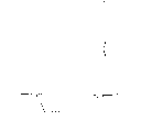
Fig. 1 is the schematic diagram of the household freezer of band screw transmission strap, has been used in combination the present invention at this this household freezer;
Fig. 2 is the schematic diagram of the household freezer of band screw transmission strap and center cage blower fan, has been used in combination the present invention at this this household freezer;
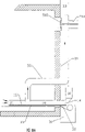
Fig. 3,4 and 5 has drawn the detail drawing that has and do not take out of the pipe/conduit layout of mouthful deflector at the one first mouthful of place that is positioned at household freezer shown in Figure 1;
Fig. 6,7 and 8 has drawn the detail drawing that has and do not take out of the pipe/conduit layout of mouthful deflector at the one second mouthful of place that is positioned at household freezer shown in Figure 1;
Fig. 9 is that control appliance of the present invention is used in combination the schematic block diagram in household freezer shown in Figure 1;
Figure 10 is the schematic diagram of the discharge tube to refrigeration unit from household freezer, wherein this discharge tube is controlled to keep required refrigerant concentration in household freezer and conduit;
Figure 11 is the schematic block diagram of the control appliance of discharge tube that household freezer shown in Figure 10 is drawn;
Figure 12 is the schematic diagram that has been used in combination duct type household freezer of the present invention at this;
Figure 13 is the schematic block diagram that control appliance of the present invention is used in combination in duct type household freezer shown in Figure 12;
Figure 14 is the detail drawing that the pipe/conduit after spiral household freezer shown in Figure 1 improves is arranged;
Figure 15 is the schematic diagram in one first alternate embodiment of the pipe/conduit layout at a household freezer mouth place;
Figure 16 is the schematic diagram in one second alternate embodiment of the pipe/conduit layout at a household freezer mouth place; With
Figure 17 is the schematic diagram in one the 3rd alternate embodiment of the pipe/conduit layout at a household freezer mouth place.
The specific embodiment
Referring to Fig. 1, household freezer 10 comprises thermal wall, the end, top and internal volume 12.One or more circulating fan 13 (or center verdant blower fan 11 as shown in Figure 2) is positioned near the internal volume 12.Conveyer belt 16 has the pattern of helical or spiral, by household freezer 10 conveying products.The product that is cooled off passes through end opening 14, and from suitable for reading 15 outputs from household freezer 10, perhaps opposite.Though following discussion is especially at spiral household freezer, other household freezer designs, and for example the duct type chilling unit also can adopt the present invention.
One group of nozzle enters volume 12 with relevant pipeline (not shown) with cryogen (for example carbon dioxide, nitrogen etc.).Freezing control system is based on temperature, and provides signal to the control valve on the refrigerant input supply line, makes the refrigerant fluid that reaches in the case to the fixed temperature requirement with output.
Referring to Fig. 3, household freezer 10 comprises conduit tube component 17 at inlet 14 places.Conduit tube component 17 provides the device that refrigerant vapor is siphoned away from conveyer belt 16.Conduit tube component 17 is across conveyer belt 16.The inlet 14 of household freezer 10 is connected to flat board 35 under little gap Outer Tube 20 and the band.The epimere of conveyer belt 16 crosses dull and stereotyped 35 also by Outer Tube 20, then is far from it with 16 hypomere.Deflector 32 is between conveyer belt epimere and the hypomere, and is excessive from household freezer too early to prevent steam.
Second end of standpipe 23 is connected to one 90 degree bend pipe 24, and it can change the width of conduit.What be connected to bend pipe 24 second ends is a horizontal duct 25, and it is across conveyer belt 16 but wideer than standpipe 23.Horizontal duct 25 stops in its size and horizontal duct 25 similar plate 34 places.Plate 34 comprises the opening that holds blower fan 26.Preferably two multiple-blade center hub air blasts 26 are installed side by side.Blower fan 26 is driven by the motor 27 that is installed in household freezer 10 outsides.Strike on the tank wall in zone 28 from the steam of horizontal duct 25 outputs, and disperse enters internal volume 12.Deflector can be used to guide steam flow upwards, or dypass returned content long-pending 12 downwards.
As mentioned above, present embodiment detaches conveyer belt 16 with the refrigeration steam, shown in arrow among Fig. 3.The sub-fraction steam leaves case 10 by Outer Tube 20, and most of steam is imported the internal volume 12 of case 10 again.The steam of overflowing by end opening 14 is collected in the spill case 31.Spill case 31 is cleared up by the exhaust system that schematically shows with external riser 33.With this form, steam is discharged out the room that is placed with case 10 and drains away from the staff.
As shown in Figure 4, be preferably under the hypomere of conveyer belts 16 in the spill case 31 an overflow deflector 38 is set, its outer wall from case 10 extends horizontally to and slightly exceeds conveyor rollers 29, the then vertical epimere part that arrives a little less than conveyer belt 16.Overflow deflector 38 is collected from 14 steams of overflowing that enter the mouth, for the outflow that stops steam is provided with another barrier.
As shown in Figure 5, in an alternate embodiment, spill case 31 comprises an overflow deflector 42, and it extends along the profile of the hypomere of conveyer belt 16 and around conveyor rollers 29, arrives the epimere part a little less than conveyer belt 16.In this alternate embodiment, roller deflector 41 is positioned near the conveyor rollers 29, is between the epimere and hypomere of conveyer belt 16.Roller deflector 41 and overflow deflector 42 have been set up and have further been prevented the barrier that steam is excessive.
The outlet 15 of household freezer 10 has also been carried out local improvement with additional guide pipe fitting (see figure 6).As inlet 14, outlet 15 is escaped to stop air to enter with steam by the pipeline shape guard shield of being made up of several workpiece that connect mutually 49.One band lower plate 50 originates in conveyor rollers 59 and is close to its part forward, and extends in household freezer 10.Pipe side part (not shown) originates in the edge of refrigeration wall and extends in the case.The inner edge of band lower plate 50 and the inner edge of side part constitute a common edge case 10 planted agents.The top 51 of pipeline 49 is exactly the top cover of household freezer.Also be fixed on the household freezer top cover 51 across conveyer belt 16 vertically arranged deflectors 52.Gap between deflector 52 and the conveyer belt 16 is by the decision of the product that cooled off, and preferably can regulate.Deflector 52 should be included in the side of pipeline 49, but is not the inner edge place that must be in the side part.
The position of outlet 15 is depended on the height of going up pump unit 53.As vertically disposed deflector 52, depend on the product that is cooled off apart from the gap of conveyer belt 16 with going up pump unit 53.Utilize this pipeline configuration, constituted a residual chamber, near itself and the end opening 14 in the Outer Tubes 20 similar.In order to reduce the effusion with steam of entering of air, between the upper and lower of conveyer belt 16, be provided with additional deflector 54.Spill case 55 is collected from exporting 15 steams of overflowing and passing through conduit 54 with its discharge.
As shown in Figure 7, as inlet 14, be preferably in layout one overflow deflector in the spill case at outlet 15 places.Overflow deflector 57 is in the spill case 55, is under the hypomere of conveyer belt 16, extends horizontally to slightly to exceed conveyor rollers 59 parts the then vertical epimere part that arrives a little less than conveyer belt 16 from the outer wall of case 10.Overflow deflector 57 is collected from exporting 15 steams of overflowing, and sets up the barrier that further prevents vapor drain.
As shown in Figure 8, in an alternate embodiment, spill case 55 comprises an overflow deflector 62, and it extends along the profile of the hypomere of conveyer belt 16 and around conveyor rollers 29, arrives the epimere part a little less than conveyer belt 16.In this embodiment, roller deflector 61 is positioned near the conveyor rollers 29, is between the epimere and hypomere of conveyer belt 16.Roller deflector 61 and overflow deflector 62 have been set up and have further been prevented the barrier that steam is excessive.
Best two mouths 14 and 15 all are with pump unit 30 and 53.Respectively positiver sealing for adjacent channel 20 and 49 is all arranged, as shown in Fig. 3 and 6 with going up pump unit 30 and 53.Provide by exhaust system with the suction of going up pump unit 30 and 53, be expressed as outer catheter 33 and 56 herein.The function of this pump unit is dual.At first, it makes the air capacity minimum that enters pipeline.Secondly, it offsets the effect of gravity to refrigerant vapor, makes the steam of all effusions leave conveyer belt 16 risings.By making the steam level in the pipeline keep high as far as possible, it is all diluted that all enter the air of pipeline.In addition, it has been found that and be with pump unit can reduce the layering of pipeline inner vapor.
The control program of household freezer 10 is based on the monitoring near vapor concentration each mouthful 14 and 15.Sensor-based system comprises the gas analyzer of vapor concentration in each pipeline configuration of monitoring.Therefore, Outer Tube 20 has sensor 40, and go up pipeline 49 sensor port 60 is arranged.Generally speaking, best sensing station is the inboard of pump unit 30 and 53 preceding guide lug on tape.Control program is based on the poor of cooling gas concentration between two pipelines.For the purpose of contrast, preferably use two positions of independent analyzer monitoring.Therefore, need suitable pipeline pipeline network, autocontrol valve and timing means (not shown).
Fig. 9 has provided microprocessor 81, and it provides a kind of by-pass valve control as required means regularly, obtains qualified reading with the position from each using gases analyzer.One provides a frequency adjustment signal for the variable speed drive device 82 that drives blower motor 27 based on the algorithm of each pipeline concentration difference substantially.This algorithm is optimized to FREQUENCY CONTROL the degree that the concentration difference minimum is achieved.The pattern of predetermined set-points does not adopt.Say in essence, the correction of the frequency of variable speed drive device 82 is based on the concentration extent.Difference is big more, and is big more to the level of corrections of frequency.
This algorithm has two kinds of patterns substantially: near limit or unstable state.For near limit, this control algolithm is a closed loop that is done as follows: press preset time and collect vapor concentration sample, more collected sample, and difference correction blower fan frequency per sample from each pipeline at interval.For unsteady state condition, for example in the temperature-fall period of household freezer 10, the blower fan frequency is to proofread and correct as the function of the rate of change of jet velocity and/or household freezer rate of temperature change.
In Outer Tube 20, set up the steam curtain one by the conduit tube component 17 that control system is regulated.Steam curtain one speech is defined herein as and means the steam forward position of generation from whole steams (concentration level of internal volume 12) to whole air transition district.In needs remain on Outer Tube 20, the thickness in this forward position is undemanding.If this forward position remains on mouthful 14 outsides, then the rotation of blower motor 27 will be fast inadequately.If there is not the steam forward position to form in pipeline 20, then the rotation of motor 27 is with too fast.
Keeping the key of high level of purity in case 10 is the foundation in Outer Tube 20 inner vapor curtains or steam forward position.If upper outlet 15 and lower inlet 14 are gas UNICOM each other, this could success.When forming the steam curtain in the pipeline 20, in pipeline 49, also form the steam forward position.
The extraction of reusable steam flow
Suppose that steam curtain system exists and plays a role, the present invention allows to extract the high-purity steam flow.In household freezer 10, inner blower system (fan unit 13 or center verdant fan unit 11) provides and has mixed intact environment.Because this thorough mixed environment is included in the case 10, the high-purity steam flow can extract from any position of the internal volume 12 in the case 10.Therefore, the high-purity steam flow can extract from any position, for example comprise near the outer wall of case 10 or its, mouthfuls 14 or 15 or its near, and near the center of internal volume 12 or its.This high-purity steam flow can shift out with the control discharging modes, and in the leading-in box 10 that liquefies also once more subsequently.
Referring to Figure 10, extraction opening 101 comprises the conduit 102 on the heat-insulating top that is sealed in case 10.Plate 100 is under the lower end of conduit 102, with armour tubing in the cleaning process of household freezer.An other end of conduit 102 is connected to isolating valve 103.Additional conduits 104 is connected to the other end of isolating valve 103.The downstream of conduit 104 is connected to the blower drum 105 that is driven by motor 106.
The conduit tube component that extends to blower drum 105 from extraction opening 101 will comprise the subatmospheric steam of pressure, so this conduit tube component requires to have the suitable seal of pipe fitting.Be connected to blower drum 105 outlet be the additional conduits 107 that ends at isolating valve 108.Crossing isolating valve 108, is that liquefaction is the refrigerating system 120 of reusable steam flow.
The conduit 107 in the downstream of blower drum 105 comprises some devices, and they comprise a static pressure sensing location 110, temperature indicator 111, air-flow metering device 113 and control valve 109.In order part or all steam flow to be shifted from refrigerating system 120 where necessary, need control valve 109.The service performance of monitoring blower drum 105 is to adopt static pressure (by from the reading of upstream conduit 104 pressure sensors 115 of blower drum 105 with from the reading of the pressure sensor 110 in the downstream conduit 107 of blower drum 105).The upstream of blower drum 105 is gas analyzers 112.
Extract steam from case 10 and be subjected to accurately control, and depend on the control system of steam curtain balance sysmte.Identical with the control program of steam curtain, the control (exhausting line blower motor frequency) of extracting steam flow from case 10 is based on the comparison to the steam flow concentration in gas concentration in pipeline 20 and 49 and the exhausting line conduit 104.The pipeline concentration value can be the mean value of each sensor 40 and 60 monitoring concentration, also can be the single-measurement value of taking from arbitrary sensor.
The basic principle of control program is the concentration that keeps the highest in exhausting line, and secondly, makes the flow maximum that extracts steam under the condition in the steam forward position of not destroying in the pipeline to be set up.Test shows, and is quite big in the concentration value difference, when being in 10% to 50% magnitude, can realize the control to exhausting line blower motor frequency.Therefore, control program is monitored concentration and is kept the difference between the concentration to be in predetermined maximum deviation value.The correction of blower frequency is based on the concentration extent and how approaching maximum deviation value is satisfied.Before exhausting line concentration reduces, descending will obviously appear in gas concentration in the pipeline.Moreover the concentration level that the remarkable reduction of injection rate also is used to refer in the case 10 is estimated and will be descended.
Control model has 3 kinds of (see figure 10)s.Pattern one is closed for first isolating valve 103 on the exhausting line.This condition seemingly exhausting line not to be connected to household freezer the same.The exhausting line control system is idle substantially.
All the sensors 110,111,112,113 and 115 on the exhausting line all has microprocessor 81 monitoring (seeing Figure 11).Microprocessor 81 is given control valve 109 and is provided control signal with the speed-changing driving device 130 that correct frequency is handled blower motor 106.
Pattern two is that first isolating valve 103 is opened, but second isolating valve 108 cuts out.In this pattern, exhausting line such as same takeoff line are because all are discharged in the exhausting line by control valve 109 by the steam that extraction opening 101 leaves.This condition can appear when refrigerating system 120 goes wrong suddenly.Can make its impact keep minimum by importing air-flow fast again to internal volume 12 environment.
Pattern three, the typical module of operation takes place when isolating valve 103 and 108 is all opened.In this pattern, steam is extracted out in case 10, and sends into refrigerating system 120.Reiterate that the target of control program is to make the vapor concentration level in the exhausting line the highest.
The exhausting line control program depends on steam curtain control program.When exhausting line was operated, steam balance curtain system is in a basic balance discharged the refrigeration that dead loss provided of household freezer mouth 14 and 15 for steam.The remainder of steam is discharged household freezer 10 by exhausting line.If excessive from the speed that case 10 extracts, the steam balance sysmte shows disturbance, because too much steam is discharged, air is infiltrated to be increased.If extraction speed is low excessively, exhausting line system optimization not then, and need to increase by the flow of blower drum 105.If the flow in the exhausting line has satisfied the ability of refrigerating system, refrigerating system 120 maximization, and any excess vapor flows through mouthfuls 14 and 15, for the steam curtain provides extra support.
Duct type household freezer structure
The duct type household freezer is operated in the mode that is similar to spiral household freezer, makes internal environment keep high vapor concentration.To be pipeline household freezer mouth generally be on the equal height with respect to the bottom of household freezer its main distinction.As a result, gravitational effect is general in sped structure not as it in the duct type household freezer.The present invention controls air and enters the duct type household freezer by allowing the small part steam to leave each pipeline opening at least.
A kind of duct type household freezer 200 is shown in Figure 12.For exemplary purposes, product through port 201 enters case 200, and through port 202 these household freezers of output.Product is transferred by household freezer 200 on conveyer belt 203.The refrigeration fluid enters household freezer by spraying system 204.The amount that is input to refrigerant in the household freezer 200 be based on spray line on the related temperature control method of control valve, be well-known for those skilled in the art.
Provide additional conduits and blower system near each refrigeration mouth place, be used for controlling and reduce air and infiltrate the output out of control of household freezer and steam from case 200.Related principle is similar to the method that above-mentioned spiral household freezer adopts.At inlet 201, be furnished with the blower fan 210 of each free its own motor 211 driving of guide-tube structure and Duo Tai.Steam imports with direction shown in the arrow 212.Steam is pulled into the conduit tube component 213 of rare one section bend pipe.Conduit tube component 213 can have the multistage bend pipe, and must be across the width of conveyer belt 203.This steam of the bottom-boot of conduit tube component 213 impacts the steam of attempting to leave by the case mouth household freezer 200.In duct type household freezer 214 or slightly exceed the steam that this pipeline place is formed up to the air forward position.
Pipeline guard shield 214 is seated on the base plate 216, and the control steam is discharged the mode of this mouthful.Be in pipeline 214 preceding guide lug be one to help to make air to infiltrate the minimum pump unit 231 of being with.The design class of this pump unit 231 is similar to unit used on the spiral case 30.Be collected in the spill case 217 from 201 steams of overflowing that enter the mouth, and by conduit 230 dischargings.Gas sensor 215 is used for monitoring the vapor concentration in the pipeline 214.Gas sensor 215 preferably is positioned at the inboard with the preceding guide lug of going up pump unit 231.
Require to have similar structure in outlet 202.Adjacent openings 202 is provided with the blower fan 220 of each free its own motor 221 driving of conduit and Duo Tai.Steam imports shown in arrow 222.Steam is pulled in the conduit tube component 223 of rare one section bend pipe.Conduit tube component 223 can have the multistage bend pipe, and across the width of conveyer belt 203.The bottom of conduit tube component 223 is guided this steam and is impacted and attempt by exporting 202 steams that leave household freezer 200.As mouth 201, transition conduit 224 is seated on the base plate 226, discharges the mode of this mouthful with the control steam.Vapor concentration using gases sensor 225 in the monitoring pipeline 224.Be in pipeline 224 the edge be to be with pump unit 241.Be collected in the spill case 227 from exporting 202 steams of overflowing, and by conduit 240 dischargings.
As mentioned above, in each pipeline 214 and 224, all vapor concentration is monitored.Device 281 (seeing Figure 13) based on microprocessor provides a kind of valve device regularly of controlling the pipe network (not shown), obtains the acceptable reading of each position to utilize an independent gas analyzer 280.Control algolithm is based on the concentration difference in the pipeline, promptly discusses at spiral household freezer as top.In order to make the concentration in the case 200 the highest, it is minimum that the concentration difference in the pipeline is wanted.Because pipeline opening 201 and 202 includes catheter device, thus a cover blower system with fixing frequency operation, and one second cover blower system has controlled variable frequency.The gravity head of this fixed frequency blower system simulation Lock-in in the spiral household freezer.By measuring the poor of mouthful concentration 215 and 225, the air blast of variable-ratio is regulated accordingly.
For example, consider that mouth 201 has the blower system 211 of variable-ratio, and mouth 202 has fixed frequency blower system 221.If the concentration that sensor 215 is read than the height of sensor 225, then will improve the frequency of this air blast.If the concentration that sensor 215 reads is low than sensor 225, then the frequency of air blast will reduce.The amplitude that the blower system of variable-ratio is proofreaied and correct is according to the concentration extent.Difference is big more, and is also big more to the correction of blower motor frequency.
As spiral household freezer steam balance control method, duct type household freezer algorithm has two kinds of patterns basically.For near steady-state condition, this control algolithm is a closed loop that is done as follows: press preset time and collect vapor concentration sample, more collected sample, and difference correction blower fan frequency per sample from each pipeline at interval.For unsteady state condition, for example in the temperature-fall period of household freezer 200, blower frequency is to proofread and correct as the function of the rate of change of jet velocity and/or household freezer rate of temperature change.
From case 200 interior extractions out is that the used method of reusable steam and spiral household freezer is similar.As the spiral household freezer, its crucial purpose is to keep high level of purity in case.Therefore, in order successfully to extract the high-purity steam flow from case 200, two steam curtains all need to work.The extraction opening of exhausting line 250 can be in any position that is in case 200, and is the best with the top surface or the basal surface of case 200.The front is identical with regard to the operation of the exhausting line that spiral household freezer is discussed for the duct type household freezer.In Figure 12, this scheme is by isolating valve 103 expression, corresponding to the initial valve of exhausting line shown in Figure 10 system.
Air to be infiltrated and the steam minimum purpose of overflowing out of control in order satisfying, can to adopt the chilling unit of several alternative type.The following example is applicable to spiral household freezer substantially, but also can adopt in other household freezer, for example the duct type household freezer.The alternate design of the conduit 17 of neighboring entry 14 is at first considered in this discussion.The geometry and the control method that substitute conduit provide subsequently, connect again with in household freezer, extracting the replacement scheme of steam flow.
The main purpose of conduit tube component 17 is uniform flow of vapor models of setting up across the width of conveyer belt 16.At first, the matching requirements of setting up the steam curtain uses wherein steam flow with the axial flow blower of the direction parallel with the axis of blower motor by blade.But axial flow blower gives and to be entered, by and discharge in the air-flow of conduit tube component 17 and bring sizable eddy current into.The bending section of prismatic blade, deflector and conduit or shaped segment can make in contiguous mouthful 14 the Outer Tube 20 the eddy current effect minimum along the conveyer belt air flow.
The upstream effect minimum of axial flow blower when implementing this suction method in order to make, the deflector of insertion one centering in horizontal duct 25 (see figure 3)s.This deflector extends to the bottom from the top of conduit 25, and this conduit is separated into two less rectangular conduit.Use and do not use the test of this deflector to show that its effect for air-flow is marginal, but do not produce negative interaction certainly.One is also studied across conduit and the horizontal deflector that is on the height.The same with vertical deflector, it is very little to the effect of the air-flow in the Outer Tube 20.Similarly deflector also can insert in the vertical conduit 23.Equally, its objective is the viewed extensive perpendicular flow pattern that in conduit tube component, forms of destroying.In vertical conduit 23, two or more blades can be set, play the effect that air-flow is led straight device.In addition, in vertical conduit 23, used the deflector that is parallel to the conveyer belt path,, hindered steam and detach conveyer belt,, realized flowing of balance to attempt in Outer Tube 20, regulating specific flow region as retention device.But for the deflector solution that proposes suboptimum, cost and cleaning problem also are very strong influence factors.
When Fig. 3,4 and 5 provides preferred embodiment, provided a kind of alternate design that realizes lifting from suction among Figure 14 again.The main difference of two kinds of designs be the to enter the mouth guide-tube structure at feedway 21 places and from the air-flow of blower fan outlet 28.Comparison diagram 3 and Figure 14, the design of Figure 14 has replaced interior conduit 22 and part vertical pipe 23 with a deflector 300 at an angle.Notice that interior conduit 22 further moves in the case 10 along the conveyer belt path, and remains the leading edge that enters conduit tube component.At the trailing edge of interior conduit 22 with become between the leading edge of angle deflector 300 to have gap 303.In addition, band lower plate 35 has prolonged, and constitutes a common edge with interior conduit 22.And 303 in gap is present on the horizontal plane that is parallel to the conveyer belt path.The sidewall height of interior conduit 22 has extended to the determined sidewall of terminal that becomes angle deflector 300 and has combined.
Adopt the geometry of Figure 14, for the steam of attempting to leave along conveyer belt 16 this case, interior conduit 22 plays the effect of regulating pipeline.Upwards the steam of suction lead leaves the blower fan district by conduit 301, and is imported into the internal volume 12 of case 10.When band lower plate 35, to regulate pipeline 22 and gap 303 be not combination when existing, systematic function will reduce, and also not good to the control of the steam that leaves household freezer.But a kind of the changing form of this structure is into the hole that angle guide's plate 300 can comprise the band adjustable cap, to allow the different extraction models of exploitation.This hole across the span of conveyer belt can, can be separately not equidistant, and be used for the air-flow of balance external pipeline 20 yet.Linkage is connected to this mouth to provide manually or motorized adjustment, does not require the inside near household freezer.
For conduit tube component 17, with regard to spiral household freezer, preferred structure comprises two blower fans and two motors.Blower fan is an axial-flow type, and for the multiple-blade type with a big center hub arranged.For some conduit geometry, preferred blade shape is centrifugal.But centrifugal blower becomes uneven when occurring freezing on the blade, so adopt axial flow blower in the present invention.For two blower fans of installation arranged side by side, when adopting this suction method, preferred rotation direction is arranged for each blower fan.For two blower fans three kinds of possible structures are arranged: two blower fans rotate in the opposite direction, and common flow region is upwards arranged between two blower fans; Two blower fans rotate in the opposite direction, and downward common flow region is arranged between two blower fans; And two blower fan rotate with equidirectional.This a kind of structure the best in back.
Outside testing divided by multiblade fan, also finished the test of carrying out with big twayblade blower fan.Relevant conduit improves, and is desired than big opening to deal with, and schematically is shown in Figure 15.When the suction in the independent twayblade blower fan enhancing of the employing conduit, test demonstrates, because the restriction that the geometry of conduit/axle causes has produced the inside air-flow along motor drive shaft of discharging place that originates from blower fan.By annular disk is installed to forbid interior stream on motor drive shaft, this harmful flox condition has weakened.When adopting preferred conduit geometry, an independent twayblade blower fan is expected to become a kind of acceptable alternative form of two blower fan schemes.
In order in Outer Tube 20, to obtain the air-flow of balance along conveyer belt, steadily output to outside the Outer Tube 20 for making steam flow in the geometry design of conduit, other catheter shape is studied.A kind of feasible alternative form is that this conduit is included in the household freezer.Two kinds of change types to inner catheter are studied, and are shown in Figure 15.As in decision design, steam siphons away from conveyer belt by conduit 401, and discharges at blower fan 403 places.In a kind of changing form, shown in solid line among Figure 15, steadily to discharge for making near conveyer belt 16 steam flows, air-flow turns to twice in conduit 401.Second kind changes form, and as shown in phantom in Figure 15, in order to weaken eddy current effect, air-flow is turned to three times in conduit change type 402.The advantage that increases the bend pipe number is that the eddy current effect that blower fan is produced obtains bigger weakening.But the number of bend pipe is many more, and the needed horsepower of motion same amount steam is big more.
The major defect of inner catheter design relates to the ability of cleaning and checked the conduit globality before cooling off household freezer 10 in constant mode as shown in figure 15.As shown in figure 16, be installed in outside the case by the major part with conduit tube component 501, the cleaning problem can easily solve.Basically, conduit 501 roles identical with shown in Figure 15.When the cleaning problem had reduced, there was different problems in the outside of conduit.At first, catheter wall need carry out heat insulation, otherwise the freezing capacity of household freezer will reduce.In addition, conduit 501 may be in the suction side of blower fan, and the susceptibility that air is infiltrated increases.When motor during close conveyer belt, its position is best.And on the other hand, conduit tube component must possess enough height so that from blower fan, to the eddy current effect minimum of air-flows in the pipeline 20.
Another embodiment of the present invention with aforesaid to siphon away steam from conveyer belt opposite, is to draw steam along conveyer belt.Referring to Figure 17, two kinds of possible conduit geometry have been provided.The key that makes this method success is downward along the enough steams of conduit 601 promotions, blocks because the steam by lower ports 14 effusions is attempted in the gravity effect.Adopt this suction method, the many places bend pipe is preferably arranged in the conduit 602, so that near the eddy current minimum in the air-flow conveyer belt 16.In the bottom of conduit tube component, but a leveling board 605 constitutes the top of Outer Tube 20.Dull and stereotyped 605 insertion degree looks like an important parameter.In addition, 21 places in the hole, the height that transmits the last guide lug that takes conduit 601 (602) to certainly also influences the development of steam curtain.Show that in spiral household freezer, this method is lower than suction method efficient blowing the observation of being done in the process of the test of steam along conveyer belt.But the test of finishing with the pattern of structure 601 shows that the control of blower motor frequency can obtain from a pressure sensor and gas analyzer.
Preferred control method is a kind of based on the self-adjusting system near concentration difference in the pipeline of each mouthful of household freezer.Being provided with apart from mouth of gas controlling device need be left enough distances, to prevent the control of periodic indoor air stream influence to steam curtain balance sysmte.
Except adopting vapor concentration as the control information, also can be with other possible control parameter.Particularly, pressure sensor can be used for providing the indication of the good degree that the steam curtain is formed.Pressure control is based on the comparison of static pressure in the household freezer and set point pressure.This set point is according to setting up by rule of thumb to fixed temperature in the case.Regulate blower speed as required, to keep required set point pressure with respect to selected household freezer temperature.When adopting pressure control, the static pressure force measurement is preferably in two positions to carry out, and calculates pressure reduction and set point pressure comparison.Static pressure is measured near steam curtain place or its and is carried out.Referring to Fig. 3, static pressure is preferably in position 8 and the measurement of 19 places in the conduit 17.
The present invention also allows the steam curtain manually to be controlled by operating personnel, and these operating personnel are equivalent to microprocessor, takes action according to the vapor concentration difference of measuring in each pipeline.Experienced operating personnel can be according to the sign directly perceived in the pipeline, and for example time or vaporous cloud (run into the interior discharge steam flow of Outer Tube owing to infiltrate air, aqueous vapor condensation wherein forms) are controlled the steam curtain.Operating personnel are connected to adjustment the frequency signal of drive unit of the variable-ratio of blower motor.Manually the shortcoming of control is no matter when this household freezer turns round, and all needs operating personnel.
To the control of extracting steam from case is according to the highest and automatic control of the vapor concentration that makes exhausting line and household freezer.But, also can use other parameter.For example, can measure the flow velocity in the exhausting line, and control the frequency drives device of exhausting line blower system according to steam by the dead loss of household freezer mouth.In addition, differential static pressure can run well the index of degree as air blast.Adopting tonometric advantage is that reading is static state and therefore insensitive to freezing.The frequency drives device of exhausting line blower system also can be by operate in manual mode.As the manually control of steam curtain, operating personnel will make a policy according to used index method, the air-flow activity in perception and the control exhausting line.
The another kind of control method that realizes high vapor concentration in pipeline configuration 200 (seeing Figure 12) is as follows.At first, by increasing extra sweep to conduit tube component and conduit tube component 213 and 223 being improved from shape shown in Figure 12.In this case, steam to air forward position is formed in Outer Tube 214 and 224.Second change is that the fixed frequency blower system is replaced with the variable drive system of controlled frequency.Now, two cover blower systems are by microprocessor 281 control, and still, blower system 211 and 221 operating frequency can be the same or different.
For this system, control is based in principle because the overvoltage shape condition that liquid cryogen evaporation causes, rather than keep near the interior concentration difference itself of pipeline each mouthful.But,, and when vapor concentration changes, take corrective action in any case two pipelines are monitored.For example, if reduce in pipeline inner vapor concentration, then the frequency of two blower systems all will improve.This control method is than more expensive with regard to the described method of preferred structure, because need extra conduit and also may need the second cover speed change frequency drives device.
To consider to adopt the resulting advantage of the present invention now.Steam purity in the household freezer keeps higher level, because air can easily not enter this case.Enter air in the case and be mingled with and make valid function better less, because refrigeration does not spend in the cooling that enters air.Moreover the little air of infiltration household freezer makes the steam flow of extracting out from case in the mode of control that is used to circulate have high-purity.
One aspect of the present invention is by a mouth at household freezer, installs in conjunction with having adopted control device of the present invention to realize for preferably nethermost mouthful neighbouring.Particularly, will attempt to leave the device that the steam of household freezer leads back once more improves.For spiral household freezer, prior art has adopted blower fan and conduit that steam is led back in the case once more, but there is limitation in these systems, and its output steam flow is by using manually control of slide plate.The result is inhomogeneous by the flow model of the steam flow of conveyer belt mouth output household freezer.For preventing that air from infiltrating the flow velocity that this conditional request is higher.The present invention has adopted conduit tube component and blower fan system, and steam is detached the case mouth glibly, and leads back in the case once more.As mentioned above, a small amount of steam leaves by the case mouth, infiltrates to prevent air.When household freezer was recovery system a part of, the flow velocity that reduces by the case mouth just became very important.
It is the control scheme that equilibrium freezing case inner vapor is adopted that the present invention has improved prior art.The system of prior art has adopted the blower system that drives with constant frequency or variable drive assembly.In addition, blower frequency and jet velocity link together.A restriction for this method is to lack control when not spraying, and this causes the loss of refrigeration output subsequently.When linking when blower frequency and based on the system that responds to visible vaporous cloud, control becomes depends on local relative humidity level.Room that humidity is low and the dry products that will cool off will not possess effective control.In the control that keeps the steam balance, successfully adopted TEMP, so this selection scheme is otiose in essence.These described control schemes provide the index of become a mandarin air and outflow steam all not from two household freezer oral groove communications breath.
The present invention has adopted the control system of using gases analyzer, provides steam to keep the index of degree in case by the concentration of monitoring two mouthfuls.Moreover the present invention does not have the pre-determined model of blower frequency not based on the control scheme of set point.The scheme that replaces is that blower system is made a response to the purity level in the case, to realize frequency the best.
The present invention has also improved the repeated use of known system refrigerant vapor.The method of prior art requires to produce enough swabbing pressures in last lobby, the stress level of lobby is under the minimum pressure in household freezer, and is lower than atmospheric pressure.The test of this method shows, adopts this method, and is quite big from indoor additional air capacity.
Economical advantage of the present invention is that control ground extracts and is rich in steam flow and do not require a large amount of additional air, and in fact, should reduce desired additional air capacity in cycle applications.The minimizing that replenishes air is an advantage on cost.
The present invention provides extra advantage to the control scheme of cycle applications.For example at United States Patent (USP) U.S.5, in 186,008, the vapor volume that extracts for circulation is the constant multiple of jet velocity.This means of the constant multiple fluctuation of the evaporation loss of household freezer with jet velocity.Therefore, the evaporation loss of household freezer changes with jet velocity.
In the present invention, the evaporation loss of household freezer is to be fixed on certain value for given application scenario substantially.Therefore, the flow that is repeated the steam flow that uses is not a fixed ratio with respect to jet velocity.The advantage of this control method is to determine that for economically feasible repeated use system suitable gas concentration is more flexible.
Should be appreciated that noted earlier only is diagram the present invention.Those skilled in the art can design multiple substituted type and modified not deviating under the prerequisite of the present invention.Therefore, the present invention is intended to comprise that all are in substituted type, modified and change type in the claims scope.
Claims (10)
1. system that improves household freezer efficient, it comprises:
One first mouthful and one second mouthful;
Conveyor-belt apparatus is used for mobile product between above-mentioned first mouthful and above-mentioned second mouthful;
Refrigerant fluid in above-mentioned household freezer;
One first pipeline, around the part of above-mentioned conveyor-belt apparatus, above-mentioned first pipeline comprises an interior pipeline section of opening and is connected to above-mentioned first mouthful outer segment in above-mentioned household freezer in above-mentioned first mouthful of place for it;
One first recycling pipe device, it has one and is in opening and in the above-mentioned household freezer is connected to above-mentioned first pipeline between pipeline section and the outer segment above-mentioned in second opening, is used for providing therein the variable mobile of above-mentioned refrigerant fluid;
One blower fan apparatus in the first recycling pipe device; And
One first monitoring device, it comprise with above-mentioned first mouthful of juxtaposed first sensor and with above-mentioned second mouthful of juxtaposed one second sensor, be used near the concentration of the refrigerant vapor definite first mouthful and second mouthful and be used to control above-mentioned blower fan apparatus according to above-mentioned concentration, to change the flow of refrigerant fluid wherein, thereby in above-mentioned first mouthful and the transition region of second mouthful of foundation from refrigerant fluid to air, and the refrigerant fluid at above-mentioned first sensor and the above-mentioned second sensor place is moved, so that concentration is closer to each other.
2. the system as claimed in claim 1, it is characterized in that, the said flow of the above-mentioned refrigerant fluid by the above-mentioned first recycling pipe device is between above-mentioned first pipeline and the above-mentioned household freezer, and wherein above-mentioned first monitoring device makes above-mentioned recycling pipe device change the amount of said flow, thereby keep above-mentioned refrigerant fluid abundant, to set up the transition region of above-mentioned refrigerant fluid to air by the flow of the above-mentioned outer segment of above-mentioned first pipeline.
3. the system as claimed in claim 1 is characterized in that, it also comprises:
Be positioned near above-mentioned first mouthful and be in the vacuum plant of above-mentioned conveyor-belt apparatus top, be used for refrigerant fluid that certainly should place's discharge suction circulation conduit that makes progress.
4. system as claimed in claim 3 is characterized in that, it also comprises near the vacuum plant that places above-mentioned second mouthful.
5. the system as claimed in claim 1, it is characterized in that the above-mentioned first recycling pipe device comprises a conduit and variable speed fan device, the latter is set to influence the refrigerant fluid flow by above-mentioned conduit, above-mentioned conduit comprises at least one section bend pipe, to reduce eddy current effect.
6. the system as claimed in claim 1 is characterized in that, it also comprises:
Refrigerant fluid extraction opening by the outer wall of above-mentioned household freezer;
Place near the circulation conduit device of above-mentioned extraction opening, be used for refrigerant fluid from above-mentioned household freezer suction exhausting line;
One second monitoring device, it comprises one the 3rd sensor that is positioned at above-mentioned exhausting line, be used for determining the cryogen flow bulk concentration and be used to control above-mentioned circulation conduit device, wherein above-mentioned second monitoring device control above-mentioned refrigerant fluid extraction and with the above-mentioned first monitoring device co-operating, maintain the transition region of above-mentioned refrigerant fluid at above-mentioned first and second mouthfuls of places to air.
7. the system as claimed in claim 1 is characterized in that, it also comprises:
Chiller;
Above-mentioned household freezer is connected to the pipe guide of above-mentioned chiller; With
Valving in the above-mentioned pipe guide, it is connected to one second monitoring device, be used for the cryogen flow bulk concentration in definite above-mentioned pipe guide, wherein above-mentioned first monitoring device and above-mentioned second monitoring device are handled above-mentioned valving, with the refrigerant fluid flow of control, thereby keep at least one place cryogen flow bulk concentration to be in desired level by above-mentioned pipe guide.
8. method that improves household freezer efficient, household freezer comprises one first mouthful, one second mouthful, the conveyor-belt apparatus of conveying products between above-mentioned first mouthful and above-mentioned second mouthful, a kind of refrigerant fluid that is in the above-mentioned household freezer, first pipeline around above-mentioned conveyor-belt apparatus, and it comprises an interior pipeline section that opens wide and is attached to above-mentioned first mouthful outer segment in above-mentioned household freezer, one has the opening and opened is attached to second opening of above-mentioned first pipeline between pipeline section and the outer segment in above-mentioned first recycling pipe in above-mentioned household freezer, and first blower fan apparatus that is used for providing at above-mentioned first recycling pipe variable above-mentioned refrigerant fluid of flow, the step that said method comprises has:
A) induction near above-mentioned first mouthful the cryogen flow bulk concentration and above-mentioned second mouthful near the cryogen flow bulk concentration; With
B) control above-mentioned blower fan apparatus, corresponding to the cryogen flow bulk concentration of in step a), being sensed, change the flow of above-mentioned refrigerant fluid in above-mentioned first recycling pipe, and therefore, change the amount of refrigerant fluid in above-mentioned outer segment, thereby make near cryogen flow bulk concentration of sensing above-mentioned first mouthful and near above-mentioned second mouthful, sense cryogen flow bulk concentration approaching mutually.
9. method as claimed in claim 8 is characterized in that it is further comprising the steps of:
C) give above-mentioned first mouthful, above-mentioned second mouthful near and above-mentioned conveyor-belt apparatus top apply vacuum, the refrigerant fluid of discharging is upwards extracted and enters circulation conduit from above-mentioned conveyor-belt apparatus.
10. method as claimed in claim 8 is characterized in that, above-mentioned household freezer comprises that by one the pipe guide of valve is connected to a chiller, and the step that comprises also has:
Handle the refrigerant fluid flow of above-mentioned valve control, thereby make the above-mentioned cryogen flow bulk concentration at least one place remain on required level by above-mentioned pipe guide.
Applications Claiming Priority (3)
| Application Number | Priority Date | Filing Date | Title |
|---|---|---|---|
| US09/092933 | 1998-06-08 | ||
| US09/092,933 US5966946A (en) | 1998-06-08 | 1998-06-08 | Method and apparatus for retention of a refrigerant fluid in a refrigeration enclosure |
| US09/092,933 | 1998-06-08 |
Publications (2)
| Publication Number | Publication Date |
|---|---|
| CN1238446A CN1238446A (en) | 1999-12-15 |
| CN1161581C true CN1161581C (en) | 2004-08-11 |
Family
ID=22235851
Family Applications (1)
| Application Number | Title | Priority Date | Filing Date |
|---|---|---|---|
| CNB991083091A Expired - Fee Related CN1161581C (en) | 1998-06-08 | 1999-06-07 | Method and apparatus for retention of refrigerant fluid in refrigeration enclosure |
Country Status (9)
| Country | Link |
|---|---|
| US (1) | US5966946A (en) |
| EP (1) | EP0964213B1 (en) |
| KR (1) | KR100404346B1 (en) |
| CN (1) | CN1161581C (en) |
| BR (1) | BR9901787A (en) |
| CA (1) | CA2274417C (en) |
| ES (1) | ES2195532T3 (en) |
| ID (1) | ID23256A (en) |
| MY (1) | MY115411A (en) |
Cited By (6)
| Publication number | Priority date | Publication date | Assignee | Title |
|---|---|---|---|---|
| US10722631B2 (en) | 2018-02-01 | 2020-07-28 | Shifamed Holdings, Llc | Intravascular blood pumps and methods of use and manufacture |
| US11185677B2 (en) | 2017-06-07 | 2021-11-30 | Shifamed Holdings, Llc | Intravascular fluid movement devices, systems, and methods of use |
| US11511103B2 (en) | 2017-11-13 | 2022-11-29 | Shifamed Holdings, Llc | Intravascular fluid movement devices, systems, and methods of use |
| US11654275B2 (en) | 2019-07-22 | 2023-05-23 | Shifamed Holdings, Llc | Intravascular blood pumps with struts and methods of use and manufacture |
| US11724089B2 (en) | 2019-09-25 | 2023-08-15 | Shifamed Holdings, Llc | Intravascular blood pump systems and methods of use and control thereof |
| US11964145B2 (en) | 2019-07-12 | 2024-04-23 | Shifamed Holdings, Llc | Intravascular blood pumps and methods of manufacture and use |
Families Citing this family (10)
| Publication number | Priority date | Publication date | Assignee | Title |
|---|---|---|---|---|
| US20090019869A1 (en) * | 2007-07-19 | 2009-01-22 | Girard John M | System and method for vapor control in cryogenic freezers |
| US20090090112A1 (en) * | 2007-09-06 | 2009-04-09 | John Martin Girard | System and method for cryogenic enhancement to mechanical freezers |
| US20090064690A1 (en) * | 2007-09-06 | 2009-03-12 | John Martin Girard | System and method for cryogenic enhancement to mechanical freezers |
| WO2010027533A1 (en) * | 2008-09-08 | 2010-03-11 | Carrier Corporation | Microchannel heat exchanger module design to reduce water entrapment |
| US9453661B2 (en) * | 2013-03-12 | 2016-09-27 | Haier US Appliance Solutions, Inc | Control system for a dual evaporator refrigeration system |
| CN104501490B (en) * | 2014-12-04 | 2017-01-11 | 王琰 | Tunnel-type liquid nitrogenquick freezing machine |
| CN104697263B (en) * | 2015-03-10 | 2017-03-08 | 王琰 | From pre-cooling type liquid nitrogen tunnel like freezing machine |
| FR3037134A1 (en) * | 2015-06-03 | 2016-12-09 | Air Liquide | DOUBLE COLD GAS EXTRACTION HOODS EQUIPPED WITH FREEZING TUNNEL |
| US20170292764A1 (en) * | 2016-04-12 | 2017-10-12 | Michael D. Newman | Cryogenic exhaust control system and freezer having same |
| CN115077172A (en) * | 2022-07-01 | 2022-09-20 | 宁德市星光食品有限公司 | Double-screw quick freezer |
Family Cites Families (17)
| Publication number | Priority date | Publication date | Assignee | Title |
|---|---|---|---|---|
| US3412573A (en) * | 1966-09-21 | 1968-11-26 | Richard S. Pauliukonis | Cryogenic quick freezing apparatus |
| US3701263A (en) * | 1970-05-18 | 1972-10-31 | Barrett Arthur L | Direct contact food freezing |
| US3733848A (en) * | 1971-08-09 | 1973-05-22 | Airco Inc | Freezing system |
| US3728869A (en) * | 1971-12-27 | 1973-04-24 | H Schmidt | Coolant system for heat removal apparatus |
| US3914953A (en) * | 1974-05-01 | 1975-10-28 | Air Prod & Chem | Cryogenic fragmentation freezer |
| US4344291A (en) * | 1980-04-28 | 1982-08-17 | Liquid Carbonic Corporation | Cryogenic cabinet freezer |
| US4276753A (en) * | 1980-05-19 | 1981-07-07 | Formax, Inc. | Cryogenic freezing tunnel control system |
| US4528819A (en) * | 1984-05-08 | 1985-07-16 | Air Products And Chemicals, Inc. | Exhaust control for cryogenic freezer |
| US4739623A (en) * | 1987-06-11 | 1988-04-26 | Liquid Carbonic Corporation | Liquid cryogen freezer and method of operating same |
| US4800728A (en) * | 1987-09-18 | 1989-01-31 | Air Products And Chemicals, Inc. | Method and apparatus for gas flow control in a cryogenic freezer |
| US4866946A (en) * | 1988-08-05 | 1989-09-19 | Air Products And Chemicals, Inc. | Spiral cryogenic freezer |
| US4955206A (en) * | 1989-11-30 | 1990-09-11 | Liquid Carbonic Corporation | Liquid cryogen freezer with improved vapor balance control |
| US4947654A (en) * | 1989-11-30 | 1990-08-14 | Liquid Carbonic Corporation | Liquid cryogen freezer with improved vapor balance control |
| US5605049A (en) * | 1991-09-13 | 1997-02-25 | Air Products And Chemicals, Inc. | Exhaust system for a cryogenic freezer |
| US5186008A (en) * | 1991-11-25 | 1993-02-16 | The Boc Group, Inc. | Cryogenic freezer apparatus and method |
| GB9402840D0 (en) * | 1994-02-15 | 1994-04-06 | Air Prod & Chem | Tunnel freezer |
| US5460015A (en) * | 1994-04-28 | 1995-10-24 | Liquid Carbonic Corporation | Freezer with imperforate conveyor belt |
-
1998
- 1998-06-08 US US09/092,933 patent/US5966946A/en not_active Expired - Lifetime
-
1999
- 1999-05-11 ID IDP990436D patent/ID23256A/en unknown
- 1999-06-07 KR KR10-1999-0020946A patent/KR100404346B1/en not_active IP Right Cessation
- 1999-06-07 ES ES99500094T patent/ES2195532T3/en not_active Expired - Lifetime
- 1999-06-07 CN CNB991083091A patent/CN1161581C/en not_active Expired - Fee Related
- 1999-06-07 MY MYPI99002299A patent/MY115411A/en unknown
- 1999-06-07 BR BR9901787-3A patent/BR9901787A/en not_active IP Right Cessation
- 1999-06-07 EP EP99500094A patent/EP0964213B1/en not_active Expired - Lifetime
- 1999-06-07 CA CA002274417A patent/CA2274417C/en not_active Expired - Fee Related
Cited By (8)
| Publication number | Priority date | Publication date | Assignee | Title |
|---|---|---|---|---|
| US11185677B2 (en) | 2017-06-07 | 2021-11-30 | Shifamed Holdings, Llc | Intravascular fluid movement devices, systems, and methods of use |
| US11717670B2 (en) | 2017-06-07 | 2023-08-08 | Shifamed Holdings, LLP | Intravascular fluid movement devices, systems, and methods of use |
| US11511103B2 (en) | 2017-11-13 | 2022-11-29 | Shifamed Holdings, Llc | Intravascular fluid movement devices, systems, and methods of use |
| US10722631B2 (en) | 2018-02-01 | 2020-07-28 | Shifamed Holdings, Llc | Intravascular blood pumps and methods of use and manufacture |
| US11229784B2 (en) | 2018-02-01 | 2022-01-25 | Shifamed Holdings, Llc | Intravascular blood pumps and methods of use and manufacture |
| US11964145B2 (en) | 2019-07-12 | 2024-04-23 | Shifamed Holdings, Llc | Intravascular blood pumps and methods of manufacture and use |
| US11654275B2 (en) | 2019-07-22 | 2023-05-23 | Shifamed Holdings, Llc | Intravascular blood pumps with struts and methods of use and manufacture |
| US11724089B2 (en) | 2019-09-25 | 2023-08-15 | Shifamed Holdings, Llc | Intravascular blood pump systems and methods of use and control thereof |
Also Published As
| Publication number | Publication date |
|---|---|
| ID23256A (en) | 2000-04-05 |
| BR9901787A (en) | 2000-01-04 |
| CN1238446A (en) | 1999-12-15 |
| MY115411A (en) | 2003-05-31 |
| US5966946A (en) | 1999-10-19 |
| KR100404346B1 (en) | 2003-11-03 |
| CA2274417A1 (en) | 1999-12-08 |
| KR20000005980A (en) | 2000-01-25 |
| CA2274417C (en) | 2003-03-18 |
| EP0964213A2 (en) | 1999-12-15 |
| EP0964213B1 (en) | 2003-04-16 |
| EP0964213A3 (en) | 2000-04-19 |
| ES2195532T3 (en) | 2003-12-01 |
Similar Documents
| Publication | Publication Date | Title |
|---|---|---|
| CN1161581C (en) | Method and apparatus for retention of refrigerant fluid in refrigeration enclosure | |
| KR101350703B1 (en) | Blow molding machine with air conditioning | |
| CN102645108B (en) | Bottom air supply type counter flow cooling towers | |
| CN210599068U (en) | Cooling and heat insulating system suitable for high geothermal tunnel construction | |
| KR101456446B1 (en) | plume and power reduction high-efficiency counter flow cooling tower and control method thereof | |
| CN106765759A (en) | A kind of high temp tunnel fast cooling device and method | |
| CA2930917C (en) | Apparatus and method for chilling or freezing | |
| CN107850318A (en) | The indoor set of air conditioner | |
| KR102236475B1 (en) | Conveyor equipment for food cooling | |
| CN103126199B (en) | Freezing setting machine for shoes and boots | |
| CN207073909U (en) | A kind of double air outlet efficient air coolers | |
| CN108194995A (en) | A kind of air-conditioning | |
| CN107781919A (en) | The control method of air-conditioner outdoor unit, air conditioner and air conditioner | |
| KR102077521B1 (en) | A cooling tower in which a filler is formed in multiple stages and a cooling water mixing section is provided between the fillers | |
| CN108800718A (en) | A kind of low drying loss quick-freezing plant and method of freezing | |
| CN107028433A (en) | Showcase and control device | |
| CN101926380A (en) | Split fruit and vegetable high-humidity differential pressure precooling device | |
| RU2502914C2 (en) | Main gas transfer method | |
| CN212188453U (en) | Gas-liquid separation device for refrigeration house compressor | |
| CN2800188Y (en) | Double helix deepfreezing machine | |
| CN218155641U (en) | Air cooler with adjustable amount of wind | |
| KR102053589B1 (en) | Cooling tower | |
| CN104544755A (en) | Freezing shaping machine for shoemaking | |
| CN208778304U (en) | A kind of cooling blower | |
| CN218709908U (en) | Accelerated cooling device of kiln before disassembly due to service life |
Legal Events
| Date | Code | Title | Description |
|---|---|---|---|
| C06 | Publication | ||
| PB01 | Publication | ||
| C10 | Entry into substantive examination | ||
| SE01 | Entry into force of request for substantive examination | ||
| C14 | Grant of patent or utility model | ||
| GR01 | Patent grant | ||
| C19 | Lapse of patent right due to non-payment of the annual fee | ||
| CF01 | Termination of patent right due to non-payment of annual fee |