CN116073201B - 5G communication electric connector assembly - Google Patents
5G communication electric connector assembly Download PDFInfo
- Publication number
- CN116073201B CN116073201B CN202310359122.9A CN202310359122A CN116073201B CN 116073201 B CN116073201 B CN 116073201B CN 202310359122 A CN202310359122 A CN 202310359122A CN 116073201 B CN116073201 B CN 116073201B
- Authority
- CN
- China
- Prior art keywords
- metal
- connector
- insulating
- shielding
- double
- Prior art date
- Legal status (The legal status is an assumption and is not a legal conclusion. Google has not performed a legal analysis and makes no representation as to the accuracy of the status listed.)
- Active
Links
Images


Classifications
-
- H—ELECTRICITY
- H01—ELECTRIC ELEMENTS
- H01R—ELECTRICALLY-CONDUCTIVE CONNECTIONS; STRUCTURAL ASSOCIATIONS OF A PLURALITY OF MUTUALLY-INSULATED ELECTRICAL CONNECTING ELEMENTS; COUPLING DEVICES; CURRENT COLLECTORS
- H01R24/00—Two-part coupling devices, or either of their cooperating parts, characterised by their overall structure
- H01R24/38—Two-part coupling devices, or either of their cooperating parts, characterised by their overall structure having concentrically or coaxially arranged contacts
-
- H—ELECTRICITY
- H01—ELECTRIC ELEMENTS
- H01R—ELECTRICALLY-CONDUCTIVE CONNECTIONS; STRUCTURAL ASSOCIATIONS OF A PLURALITY OF MUTUALLY-INSULATED ELECTRICAL CONNECTING ELEMENTS; COUPLING DEVICES; CURRENT COLLECTORS
- H01R13/00—Details of coupling devices of the kinds covered by groups H01R12/70 or H01R24/00 - H01R33/00
- H01R13/02—Contact members
- H01R13/22—Contacts for co-operating by abutting
- H01R13/24—Contacts for co-operating by abutting resilient; resiliently-mounted
- H01R13/2407—Contacts for co-operating by abutting resilient; resiliently-mounted characterized by the resilient means
-
- H—ELECTRICITY
- H01—ELECTRIC ELEMENTS
- H01R—ELECTRICALLY-CONDUCTIVE CONNECTIONS; STRUCTURAL ASSOCIATIONS OF A PLURALITY OF MUTUALLY-INSULATED ELECTRICAL CONNECTING ELEMENTS; COUPLING DEVICES; CURRENT COLLECTORS
- H01R13/00—Details of coupling devices of the kinds covered by groups H01R12/70 or H01R24/00 - H01R33/00
- H01R13/62—Means for facilitating engagement or disengagement of coupling parts or for holding them in engagement
- H01R13/627—Snap or like fastening
-
- H—ELECTRICITY
- H01—ELECTRIC ELEMENTS
- H01R—ELECTRICALLY-CONDUCTIVE CONNECTIONS; STRUCTURAL ASSOCIATIONS OF A PLURALITY OF MUTUALLY-INSULATED ELECTRICAL CONNECTING ELEMENTS; COUPLING DEVICES; CURRENT COLLECTORS
- H01R13/00—Details of coupling devices of the kinds covered by groups H01R12/70 or H01R24/00 - H01R33/00
- H01R13/62—Means for facilitating engagement or disengagement of coupling parts or for holding them in engagement
- H01R13/639—Additional means for holding or locking coupling parts together, after engagement, e.g. separate keylock, retainer strap
-
- H—ELECTRICITY
- H01—ELECTRIC ELEMENTS
- H01R—ELECTRICALLY-CONDUCTIVE CONNECTIONS; STRUCTURAL ASSOCIATIONS OF A PLURALITY OF MUTUALLY-INSULATED ELECTRICAL CONNECTING ELEMENTS; COUPLING DEVICES; CURRENT COLLECTORS
- H01R13/00—Details of coupling devices of the kinds covered by groups H01R12/70 or H01R24/00 - H01R33/00
- H01R13/648—Protective earth or shield arrangements on coupling devices, e.g. anti-static shielding
- H01R13/658—High frequency shielding arrangements, e.g. against EMI [Electro-Magnetic Interference] or EMP [Electro-Magnetic Pulse]
- H01R13/6581—Shield structure
-
- H—ELECTRICITY
- H01—ELECTRIC ELEMENTS
- H01R—ELECTRICALLY-CONDUCTIVE CONNECTIONS; STRUCTURAL ASSOCIATIONS OF A PLURALITY OF MUTUALLY-INSULATED ELECTRICAL CONNECTING ELEMENTS; COUPLING DEVICES; CURRENT COLLECTORS
- H01R13/00—Details of coupling devices of the kinds covered by groups H01R12/70 or H01R24/00 - H01R33/00
- H01R13/648—Protective earth or shield arrangements on coupling devices, e.g. anti-static shielding
- H01R13/658—High frequency shielding arrangements, e.g. against EMI [Electro-Magnetic Interference] or EMP [Electro-Magnetic Pulse]
- H01R13/6591—Specific features or arrangements of connection of shield to conductive members
- H01R13/65912—Specific features or arrangements of connection of shield to conductive members for shielded multiconductor cable
-
- Y—GENERAL TAGGING OF NEW TECHNOLOGICAL DEVELOPMENTS; GENERAL TAGGING OF CROSS-SECTIONAL TECHNOLOGIES SPANNING OVER SEVERAL SECTIONS OF THE IPC; TECHNICAL SUBJECTS COVERED BY FORMER USPC CROSS-REFERENCE ART COLLECTIONS [XRACs] AND DIGESTS
- Y02—TECHNOLOGIES OR APPLICATIONS FOR MITIGATION OR ADAPTATION AGAINST CLIMATE CHANGE
- Y02A—TECHNOLOGIES FOR ADAPTATION TO CLIMATE CHANGE
- Y02A30/00—Adapting or protecting infrastructure or their operation
Abstract
The invention discloses a 5G communication electric connector assembly which belongs to the technical field of connectors, and comprises a first connector, a second connector, a double-buckle clamping seat, coaxial transmission shielding wires, a cable and a cylinder plug assembly, wherein the second connector is in fit connection with the first connector, a hanging plate is arranged at the upper part of the first connector, an insulating convex body is arranged at the lower part of the first connector, the second connector comprises an insulating concave body, the cylinder plug assembly is arranged on the insulating convex body and the insulating concave body, each coaxial transmission shielding wire and each cable are respectively connected with one end of each corresponding cylinder plug assembly, and the insulating convex body is in fit connection with the insulating concave body through the cylinder plug assembly so as to realize communication electric connection. The electric connector component has large communication width, meets the requirement of 5G signal quantity use and improves the transmission efficiency; the integral shielding can block external signal interference, so that the smoothness of signal transmission is ensured; the overall coordination stability is good, and the assembly and installation efficiency is high; the elastic contact better improves the stability of contact.
Description
Technical Field
The invention belongs to the technical field of connectors, and relates to a 5G communication electric connector assembly.
Background
The fifth generation mobile communication technology (5 th Generation Mobile Communication Technology, abbreviated as 5G) is a broadband mobile communication technology with high speed and low time delay, is a network infrastructure for realizing man-machine object interconnection, and has higher industrial application requirements on a transmission power electric connector (abbreviated as a connector) in the 5G communication industry.
Many intelligent communication devices need to output signals by using a connector with a high-speed output function, a plurality of electronic components are arranged on the periphery of the connector to emit signal interference to different degrees, and the connector and a connecting wire only have the function of shielding signals locally, so that the defects of delay, interruption, hysteresis and the like of signal transmission of the connector are caused; the signal quantity of 5G is multiplied, the communication width of the connecting wire is insufficient, and the transmission efficiency is low; the metal strips of the connector are mutually spliced and worn, even metal skins are rubbed off, so that contact looseness is caused, the connector has no good fixing mode after connection, the connection of the whole connector is loose, and the signal transmission is easily interrupted due to the fact that individual metal strips are indirectly loosened; and the connector is low in installation efficiency and cannot be installed quickly.
Therefore, there is a need to design a 5G communication electrical connector assembly to solve the above-mentioned problems of the connector.
Disclosure of Invention
The invention provides a 5G communication electric connector assembly, which aims to solve the problems of weak shielding of a connector applied to the field of 5G communication on signal interference, low signal transmission rate, splicing abrasion of the structure of the connector, loose connection and low installation efficiency.
In order to achieve the above purpose, the invention provides a 5G communication electric connector assembly, which comprises a first connector, a second connector, a double-buckle clamping seat, a coaxial transmission shielding wire, a cable and a cylinder column plug-in assembly, wherein the second connector is in plug-in connection with the first connector in an adapting way;
the double-buckle clamping seat is provided with a penetrating assembly hole, hanging grooves are formed in the upper parts of the two sides of the assembly hole, and the insulating convex bodies penetrate through the assembly hole to enable the two sides of the hanging plate to be sleeved and hung in the hanging grooves;
the second connector comprises an insulating concave body and a metal shielding shell, the insulating concave body is internally embedded and wrapped with the metal shielding shell, and the double-buckle clamping seat is internally embedded and wrapped with a metal shielding middle frame along the periphery of the assembly hole so as to realize shielding connection during plug-in assembly;
the cylinder column plug-in components set up on insulating convex body and insulating concave body, every coaxial transmission shielding wire and cable conductor are connected with the one end of every cylinder column plug-in components that corresponds respectively, insulating convex body passes through cylinder column plug-in components and insulating concave body adaptation grafting to realize communication electricity and connect.
As preferred, the cylinder column plug-in assembly comprises a metal hollow plug-in column and a metal sleeve, a double-row blind hole is formed in the lower portion of the insulating convex body, a metal sleeve is arranged in the double-row blind hole, the upper portion of the metal sleeve and the insulating convex body are integrally injection molded, the tail end of the metal sleeve extends to the side face of the hanging plate, a metal hollow plug-in column corresponding to the double-row blind hole is arranged in the insulating concave body, the lower portion of the metal hollow plug-in column and the insulating concave body and the metal shielding shell are integrally injection molded, the tail end of the metal hollow plug-in column extends out of the outer side face of the bottom of the insulating concave body, and the front portion of the metal hollow plug-in column is in plug-in connection with the front portion of the metal sleeve in an adapting mode, wherein the aperture of the double-row blind hole is larger than the outer diameter of the metal sleeve.
Preferably, the coaxial transmission shielding wire comprises a central transmission conductor, an outer shielding conductor, an insulating inner layer and an insulating outer skin layer, wherein the insulating inner layer wraps the central transmission conductor, the outer shielding conductor is arranged between the insulating inner layer and the insulating outer skin layer, the central transmission conductor is welded with the tail end of the corresponding metal sleeve, and the cable is welded with the tail end of the corresponding metal sleeve.
Preferably, the same metal pressing strips are arranged at the front end and the rear end of the hanging plate, each metal pressing strip is used for being welded with an outer shielding conductor of the coaxial transmission shielding wire and used for pressing outer pressing of a cable, extension blocks are arranged on the left side and the right side of each metal pressing strip, and the extension blocks and the side ends of the hanging plate are inserted into the hanging grooves and are mutually contacted with the metal shielding middle frame.
Preferably, the lower part of the insulation convex body is provided with a limit groove, the transmission plug part and the power supply plug part are formed by injection molding, the limit groove is used for arranging double rows of metal sleeves, the bottom of the insulation concave body is provided with a limit block, the transmission concave part and the power supply concave part are formed by injection molding, the limit groove is used for arranging double rows of metal hollow plug posts, the transmission plug part is in fit connection with the transmission concave part, and the power supply plug part is in fit connection with the power supply concave part.
Preferably, the tail end of the metal hollow plug is used for being connected with the PCB in a soldering mode.
Preferably, the front side wall of the metal sleeve is provided with a plurality of sheet grooves to form a plurality of arc sheets, and the front outer side wall of the metal hollow inserted column is provided with a plurality of convex hulls for abutting against the inner side walls of the arc sheets to be in elastic contact with each other.
Preferably, slots are formed in the side ends of two sides of the hanging plate, elastic inserting blocks are arranged at positions corresponding to the slots of the double-buckle clamping seat, the elastic inserting blocks are inserted into the slots, downward connecting arms are arranged on two sides of the double-buckle clamping seat, hooks are arranged on the inner sides of the bottoms of the connecting arms, clamping blocks are arranged on the outer side walls of two sides of the insulating concave body, and the hooks are connected with clamping blocks in a clamping mode.
Preferably, the side wall of the middle part of the metal sleeve is provided with a plurality of side holes.
Compared with the prior art, the invention has the beneficial effects that:
1. the central transmission conductor, the metal hollow inserted column and the metal sleeve of the coaxial transmission shielding wire are connected to the signal circuit of the PCB to form signal transmission, and the central transmission conductor has large communication width, can better meet 5G signal quantity and improves transmission efficiency;
2. an outer shielding conductor of the coaxial transmission shielding wire, a metal shielding shell and a metal shielding middle frame are connected to a grounding circuit of the PCB to form an integral shielding, so that external signal interference is blocked, and the smoothness of signal transmission is ensured;
3. the elastic inserting block of the double-buckle clamping seat is inserted into the slot where the hanging plate of the first connector is positioned, so that the double-buckle clamping seat is firmly connected with the first connector, the clasp of the double-buckle clamping seat is in buckling connection with the clamping block of the second connector, the double-buckle clamping seat is firmly connected with the second connector, the overall matching stability is good, and the assembly and installation efficiency is high;
4. the metal hollow inserting column is inserted into the metal sleeve, and the convex hulls are used for abutting against the inner side walls of the arc-shaped sheets to be elastically contacted with each other, so that the phenomenon that the abrasion is serious due to hard insertion of the traditional metal terminal is avoided.
In order to more clearly illustrate the structural features and efficacy of the present invention, the present invention will be described in detail below with reference to the accompanying drawings and examples.
Drawings
FIG. 1 is a schematic perspective view of the present invention;
FIG. 2 is a schematic diagram of a front view structure of the present invention;
FIG. 3 is a schematic diagram of an exploded construction of the present invention;
FIG. 4 is a schematic diagram of the assembled structure of an insulating male body and an insulating female body in the present invention;
FIG. 5 is an exploded view of the dual buckle holder according to the present invention;
FIG. 6 is a schematic diagram of an exploded structure of a second connector according to the present invention;
FIG. 7 is a schematic view of an exploded structure of the first connector of the present invention;
fig. 8 is a schematic diagram of an assembly structure of a first connector according to the present invention;
FIG. 9 is a schematic view of a plug structure of a cartridge plug assembly according to the present invention;
FIG. 10 is a schematic view of an exploded view of a cartridge plug assembly of the present invention;
fig. 11 is a schematic structural view of a coaxial transmission shielding wire in the present invention;
fig. 12 is a schematic view of the structure of the cable according to the present invention;
reference numerals:
1. a first connector; 2. a second connector; 3. a double-buckle clamping seat; 301. a fitting hole; 302. a hanging groove; 303. a clasp; 304. a connecting arm; 4. coaxial transmission shielding wire; 401. a central transmission conductor; 402. an outer shielding conductor; 403. an insulating inner layer; 404. an insulating outer skin layer; 5. a cable; 6. a barrel-column plug-in assembly; 601. a metal sleeve; 602. a metal hollow plug; 603. convex hulls; 604. a sheet groove; 605. an arc-shaped sheet; 606. a side hole; 7. a hanging plate; 8. an insulating protrusion; 9. an insulating concave body; 10. a metal shield case; 11. a metal shielding middle frame; 12. a metal batten; 13. an extension block; 14. a limit groove; 15. a limiting block; 16. slotting; 17. an elastic insert; 18. a clamping block; 19. arc elastic folding piece; 20. a metal exposed sheet; 21. double row blind holes.
Description of the embodiments
Unless defined otherwise, all technical and scientific terms used herein have the same meaning as commonly understood by one of ordinary skill in the art to which this application belongs; the terminology used in the description of the applications herein is for the purpose of describing particular embodiments only and is not intended to be limiting of the application; the terms "comprising" and "having" and any variations thereof in the description and claims of the present application and in the description of the figures above are intended to cover non-exclusive inclusions. The terms first, second and the like in the description and in the claims or in the above-described figures, are used for distinguishing between different objects and not necessarily for describing a sequential or chronological order.
Reference herein to "an embodiment" means that a particular feature, structure, or characteristic described in connection with the embodiment may be included in at least one embodiment of the present application. The appearances of such phrases in various places in the specification are not necessarily all referring to the same embodiment, nor are separate or alternative embodiments mutually exclusive of other embodiments. Those of skill in the art will explicitly and implicitly appreciate that the embodiments described herein may be combined with other embodiments.
In order to achieve the above objective, an embodiment of the present invention provides a 5G communication electrical connector assembly, as shown in fig. 1-3 and fig. 5-6, including a first connector 1, a second connector 2, and a double-buckle holder 3, wherein one end of the double-buckle holder 3 is engaged with the first connector 1, and the other end is engaged with the second connector 2, so that the first connector 1 and the second connector 2 are adapted to be plugged to form a connection assembly, the overall mating stability is better, the assembly installation efficiency is high, and the embodiment includes:
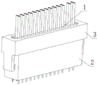
the upper part of the first connector 1 is provided with a hanging plate 7, the lower part is provided with an insulating convex body 8, the insulating convex body 8 and the hanging plate 7 are integrally formed in the transverse direction of the center of the top end surface, and a plurality of coaxial transmission shielding wires 4 and cables 5 are paved on the front surface and the rear surface of the hanging plate 7, wherein the coaxial transmission shielding wires 4 are positioned on one side of the cables 5; the double-buckle clamping seat 3 is provided with a penetrating assembly hole 301, hanging grooves 302 are formed in the upper parts of two sides of the assembly hole 301, and the insulating convex bodies 8 penetrate through the assembly hole 301 to enable two sides of the hanging plate 7 to be sleeved and hung in the hanging grooves 302; the second connector 2 comprises an insulation concave body 9 and a metal shielding shell 10, the insulation concave body 9 is internally wrapped with the metal shielding shell 10, and the double-buckle clamping seat 3 is internally wrapped with a metal shielding middle frame 11 along the periphery of the assembly hole 301 so as to realize shielding connection during plug-in assembly; the cylinder plug-in components 6 set up on insulating convex body 8 and insulating concave body 9, every coaxial transmission shielding wire 4 and cable conductor 5 are connected with the one end of every cylinder plug-in components 6 that corresponds respectively, insulating convex body 8 is pegged graft with insulating concave body 9 through cylinder plug-in components 6 adaptation to realize communication electricity and be connected.
In this embodiment, on one hand, the coaxial transmission shielding wire 4 can form an insertion assembly shielding connection with the metal shielding shell 10 and the metal shielding middle frame 11, so that external signal interference can be shielded, and signal transmission smoothness is ensured; on the other hand, the coaxial transmission shielding wire 4 can form communication connection with the corresponding cylinder plug-in assembly 6, so that the communication width and the transmission efficiency can be improved, the cable 5 can form power supply connection with the cylinder plug-in assembly 6 at a corresponding point, and power can be supplied to the connection of the PCB board connected with the cylinder plug-in assembly 6.
Further, referring to fig. 7-10, the cylindrical plug assembly 6 includes a metal hollow plug 602 and a metal sleeve 601, a double-row blind hole 21 is provided at the lower part of the insulation convex body 8, a metal sleeve 601 is provided in the double-row blind hole 21, the upper part of the metal sleeve 601 and the insulation convex body 8 are integrally injection molded, the metal sleeve 601 is better secured, the tail end of the metal sleeve 601 extends to the side surface of the hanging plate 7, a metal hollow plug 602 corresponding to the double-row blind hole 21 is provided in the insulation concave body 9, the lower part of the metal hollow plug 602, the insulation concave body 9 and the metal shielding shell 10 are integrally injection molded, the metal hollow plug 602 and the metal shielding shell 10 are better secured, and then injection molding is performed after the metal hollow plug 602 and the metal shielding shell 10 are sleeved in advance in the injection molding cavity or through a jig, the tail end of the metal hollow plug 602 extends out of the outer side surface of the bottom of the insulation concave body 9, the front part of the metal hollow plug 602 is adapted to the front part of the metal sleeve 601, wherein the aperture of the metal hollow plug 602 is larger than the outer diameter of the metal sleeve 21.
Further, referring to fig. 11-12, the coaxial transmission shielding wire 4 includes a central transmission conductor 401, an outer shielding conductor 402, an insulating inner layer 403 and an insulating outer layer 404, where the central transmission conductor 401 is wrapped by the insulating inner layer 403, the outer shielding conductor 402 is disposed between the insulating inner layer 403 and the insulating outer layer 404, the central transmission conductor 401 is welded with the end of the corresponding metal sleeve 601, the cable 5 is welded with the end of the corresponding metal sleeve 601, and the end of the metal hollow plug 602 is used for soldering connection with a signal circuit of the PCB board, so that high-speed signal transmission is formed by connection of the central transmission conductor 401, the metal sleeve 601 and the metal hollow plug 602 to the signal circuit of the PCB board, where the central transmission conductor 401 has a large communication width, can better meet 5G signal quantity, and improves transmission efficiency; the connection of the power supply circuit is formed by the connection of the cable 5, the metal sleeve 601 and the metal hollow plug 602 to the PCB board,
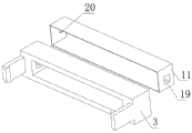
further, referring to fig. 7, the same metal strips 12 are disposed at the front and rear ends of the hanging plate 7, each metal strip 12 is used for welding with the outer shielding conductor 402 of the coaxial transmission shielding wire 4 and pressing the outer layer of the cable 5, extension blocks 13 are disposed at the left and right sides of the metal strip 12, and the extension blocks 13 and the side ends of the hanging plate 7 are inserted into the hanging grooves 302 and are in contact with the metal shielding middle frame 11. For example, in this embodiment, the metal shielding middle frame 11 is provided with an arc-shaped elastic folding piece 19 at a position corresponding to the extending block 13, the end of each coaxial transmission shielding wire 4 is peeled off to expose the central transmission conductor 401 and the outer shielding conductor 402, the end of the central transmission conductor 401 and the end of the metal sleeve 601 are welded, the outer shielding conductor 402 and the metal pressing strip 12 are welded, the insulation inner layer 403 is ensured to separate the central transmission conductor 401 and the outer shielding conductor 402, the welded metal pressing strips 12 on two sides are fixedly connected with the hanging plate 7 and then inserted into the hanging groove 302, the extending block 13 of the metal pressing strip 12 can be contacted with the arc-shaped elastic folding piece 19, so that the outer shielding conductor 402 is connected with the metal shielding middle frame 11, and after the insulation convex body 8 is adaptively inserted into the insulation concave body 9, the metal exposed piece 20 at the top end of the metal shielding shell 10 can be contacted with the metal exposed piece 20 at the bottom of the metal shielding middle frame 11, and the metal exposed piece 20 at the bottom of the metal shielding shell 10 is connected with the grounding circuit of the PCB board, so that the whole shielding can separate external signal interference and ensure the smoothness of signal transmission.
Further, referring to fig. 3-4, the lower portion of the insulation convex body 8 is provided with a limit groove 14, so as to form a transmission insertion portion and a power supply insertion portion by injection molding, and the limit groove is used for arranging double rows of the metal sleeves 601, the bottom of the insulation concave body 9 is provided with a limit block 15, so as to form a transmission concave portion and a power supply concave portion by injection molding, and the limit block is used for arranging double rows of the metal hollow insertion posts 602, and the transmission insertion portion is inserted with the transmission concave portion in an adapting manner, so that the limit groove is convenient to connect and set with the coaxial transmission shielding wire 4, and the power supply insertion portion is inserted with the power supply concave portion in an adapting manner, so that the limit groove is convenient to connect and set with the cable 5.
Further, referring to fig. 9-10, the front side wall of the metal sleeve 601 is provided with a plurality of sheet slots 604 to form a plurality of arc sheets 605, the front outer side wall of the metal hollow plug 602 is provided with a plurality of convex hulls 603 for abutting against the inner side walls of the arc sheets 605 to elastically contact with each other, the elastic contact can avoid the phenomenon of serious abrasion caused by hard insertion of the conventional metal terminal, and the elastic contact can ensure the stability of abutting contact.
Further, referring to fig. 3, the side ends of two sides of the hanging plate 7 are respectively provided with a slot 16, the positions of the double-buckle clamping seat 3 corresponding to the slots 16 are provided with elastic inserting blocks 17, the elastic inserting blocks 17 are inserted into the slots 16, two sides of the double-buckle clamping seat 3 are provided with downward connecting arms 304, the inner sides of the bottoms of the connecting arms 304 are provided with hooks 303, the outer side walls of two sides of the insulation concave body 9 are provided with clamping blocks 18, and the hooks 303 are in buckled connection with the clamping blocks 18. For example, by arranging an inclined plane at the bottom of the elastic insert 17, arranging a spring at the rear end face of the elastic insert 17, driving the elastic insert 17 to move upwards after the hanging plate 7 enters the hanging groove 302 and approaches to the inclined plane of the elastic insert 17, and locking the hanging plate 7 by the elastic insert 17 of the slot 16 when the elastic insert 17 falls into the position of the slot 16, so that the first connector 1 is fastened and connected with the double-buckle clamping seat 3; when the insulation convex body 8 is inserted into the insulation concave body 9 to reach the limit position, the clasp 303 is in clasp connection with the clamping block 18, so that the double-clasp clamping seat 3 is in fastening connection with the second connector 2.
Further, referring to fig. 7-10, the side wall of the middle portion of the metal sleeve 601 is provided with a plurality of side holes 606, so that the holding force between the metal sleeve 601 and the insulating convex body 8 can be enhanced during integral injection molding, and loosening caused by repeated plugging and unplugging of the first connector 1 is not easy to occur.
In summary, the embodiment of the invention provides a 5G communication electrical connector assembly, which is formed by connecting a central transmission conductor 401 of a coaxial transmission shielding wire 4, a metal hollow plug 602 and a metal sleeve 601 to a signal circuit of a PCB board, wherein the central transmission conductor 401 has a large communication width, can better meet 5G signal quantity, and improves transmission efficiency; the outer shielding conductor 402 of the coaxial transmission shielding wire 4, the metal shielding shell 10 and the metal shielding middle frame 11 are connected to a grounding circuit of the PCB to form an integral shielding, so that external signal interference is blocked, and the smoothness of signal transmission is ensured; the elastic inserting block 17 of the double-buckle clamping seat 3 is inserted into the slot 16 where the hanging plate 7 of the first connector 1 is positioned, so that the double-buckle clamping seat 3 is firmly connected with the first connector 1, the clasp 303 of the double-buckle clamping seat 3 is in snap connection with the clamping block 18 of the second connector 2, the double-buckle clamping seat 3 is firmly connected with the second connector 2, the overall matching stability is good, and the assembly and installation efficiency is high; the metal hollow plug posts 602 are inserted into the metal sleeve 601, and the convex hulls 603 are abutted against the inner side walls of the arc-shaped sheets 605 to be elastically contacted with each other, so that the phenomenon of serious abrasion caused by hard plug connection of the traditional metal terminals is avoided.
The technical principle of the present invention has been described above in connection with specific embodiments, but is only the preferred embodiment of the present invention. The protection scope of the present invention is not limited to the above embodiments, and all technical solutions belonging to the concept of the present invention belong to the protection scope of the present invention. Those skilled in the art will recognize that other embodiments of the invention are within the scope of the invention without undue burden.
Claims (9)
1. The 5G communication electric connector assembly comprises a first connector and a second connector which is in fit connection with the first connector, and is characterized by further comprising a double-buckle clamping seat, a coaxial transmission shielding wire, a cable wire and a cylindrical column plug-in assembly, wherein a hanging plate is arranged at the upper part of the first connector, an insulating convex body is arranged at the lower part of the first connector, the insulating convex body is integrally formed with the hanging plate in the transverse direction of the center of the top end surface, and a plurality of coaxial transmission shielding wires and cable wires are paved on the front surface and the rear surface of the hanging plate, wherein the coaxial transmission shielding wires are positioned on one side of the cable wire;
the double-buckle clamping seat is provided with a penetrating assembly hole, hanging grooves are formed in the upper parts of the two sides of the assembly hole, and the insulating convex bodies penetrate through the assembly hole to enable the two sides of the hanging plate to be sleeved and hung in the hanging grooves;
the second connector comprises an insulating concave body and a metal shielding shell, the insulating concave body is internally embedded and wrapped with the metal shielding shell, and the double-buckle clamping seat is internally embedded and wrapped with a metal shielding middle frame along the periphery of the assembly hole so as to realize shielding connection during plug-in assembly;
the cylinder column plug-in components set up on insulating convex body and insulating concave body, every coaxial transmission shielding wire and cable conductor are connected with the one end of every cylinder column plug-in components that corresponds respectively, insulating convex body passes through cylinder column plug-in components and insulating concave body adaptation grafting to realize communication electricity and connect.
2. The 5G communication electrical connector assembly of claim 1, wherein the barrel post plugging assembly comprises a metal hollow plug post and a metal sleeve, a double-row blind hole is formed in the lower portion of the insulation convex body, the metal sleeve is arranged in the double-row blind hole, the upper portion of the metal sleeve and the insulation convex body are integrally injection molded, the tail end of the metal sleeve extends to the side surface of the hanging plate, a metal hollow plug post corresponding to the double-row blind hole is arranged in the insulation concave body, the lower portion of the metal hollow plug post and the insulation concave body and the metal shielding shell are integrally injection molded, the tail end of the metal hollow plug post extends out of the outer side surface of the bottom of the insulation concave body, and the front portion of the metal hollow plug post and the front portion of the metal sleeve are in fit and plug connection, wherein the aperture of the double-row blind hole is larger than the outer diameter of the metal sleeve.
3. The 5G communication electrical connector assembly of claim 2, wherein the coaxial transmission shielded wire comprises a central transmission conductor, an outer shielded conductor, an inner insulating layer and an outer insulating layer, the inner insulating layer surrounding the central transmission conductor, the outer shielded conductor disposed between the inner insulating layer and the outer insulating layer, the central transmission conductor being welded to a corresponding metal sleeve end, the electrical cable being welded to a corresponding metal sleeve end.
4. The electrical connector assembly of claim 3, wherein the same metal strips are disposed at the front and rear ends of the hanging plate, each metal strip is used for welding with an outer shielding conductor of the coaxial transmission shielding wire and pressing an outer layer of the cable, extension blocks are disposed at left and right sides of the metal strip, and the extension blocks are inserted into the hanging grooves with the side ends of the hanging plate and are mutually contacted with the metal shielding middle frame.
5. The 5G communication electrical connector assembly of claim 2, wherein the insulating boss has a limiting groove at a lower portion thereof, and is formed by injection molding to form a transmission plug portion and a power supply plug portion, for arranging the double rows of the metal sleeves, and the insulating boss has a limiting block at a bottom thereof, and is formed by injection molding to form a transmission recess and a power supply recess, for arranging the double rows of the metal hollow plug posts, and the transmission plug portion is adapted to be inserted into the transmission recess, and the power supply plug portion is adapted to be inserted into the power supply recess.
6. The 5G communication electrical connector assembly of claim 2, wherein the ends of the metal hollow posts are adapted for solder connection with a PCB.
7. The electrical 5G communication connector assembly of claim 2, wherein the metal sleeve has a plurality of slots on a front sidewall thereof to form a plurality of arcuate tabs, and a plurality of bumps on an outer sidewall of the front of the metal hollow post for abutting against an inner sidewall of the arcuate tabs for resilient contact therewith.
8. The 5G electrical connector assembly of claim 1, wherein the side ends of the two sides of the hanging plate are respectively provided with a slot, the double-buckle clamping seat is provided with an elastic insertion block at a position corresponding to the slot, the elastic insertion block is inserted into the slot, two sides of the double-buckle clamping seat are provided with downward connecting arms, the inner sides of the bottoms of the connecting arms are provided with hooks, and the outer side walls of the two sides of the insulation concave body are provided with clamping blocks, and the hooks are in clamping connection with the clamping blocks.
9. The electrical 5G communication connector assembly of claim 2, wherein the metal sleeve has side holes in a central portion of the side wall.
Priority Applications (1)
| Application Number | Priority Date | Filing Date | Title |
|---|---|---|---|
| CN202310359122.9A CN116073201B (en) | 2023-04-06 | 2023-04-06 | 5G communication electric connector assembly |
Applications Claiming Priority (1)
| Application Number | Priority Date | Filing Date | Title |
|---|---|---|---|
| CN202310359122.9A CN116073201B (en) | 2023-04-06 | 2023-04-06 | 5G communication electric connector assembly |
Publications (2)
| Publication Number | Publication Date |
|---|---|
| CN116073201A CN116073201A (en) | 2023-05-05 |
| CN116073201B true CN116073201B (en) | 2023-05-30 |
Family
ID=86173559
Family Applications (1)
| Application Number | Title | Priority Date | Filing Date |
|---|---|---|---|
| CN202310359122.9A Active CN116073201B (en) | 2023-04-06 | 2023-04-06 | 5G communication electric connector assembly |
Country Status (1)
| Country | Link |
|---|---|
| CN (1) | CN116073201B (en) |
Citations (13)
| Publication number | Priority date | Publication date | Assignee | Title |
|---|---|---|---|---|
| JP2001085106A (en) * | 1999-09-16 | 2001-03-30 | D D K Ltd | Electric connector |
| JP2004296433A (en) * | 2003-03-07 | 2004-10-21 | Jst Mfg Co Ltd | Plug connector housing with locking mechanism, and plug connector with locking mechanism using the housing |
| JP2014222648A (en) * | 2013-05-14 | 2014-11-27 | 矢崎総業株式会社 | Connector device |
| CN208637712U (en) * | 2018-07-27 | 2019-03-22 | 深圳市长江连接器有限公司 | A kind of anti-drop connector |
| CN111082242A (en) * | 2018-10-19 | 2020-04-28 | 华为机器有限公司 | Connector, circuit board and communication equipment |
| CN111313172A (en) * | 2018-12-12 | 2020-06-19 | 现代自动车株式会社 | Integrated multi-pole connector |
| CN112542741A (en) * | 2020-11-17 | 2021-03-23 | 上海航天科工电器研究院有限公司 | Electrical connector |
| CN113178720A (en) * | 2021-04-20 | 2021-07-27 | 杭州耀芯科技有限公司 | Pluggable free space photoelectric hybrid connector |
| CN113224597A (en) * | 2021-04-16 | 2021-08-06 | 领翌技术(横琴)有限公司 | Cable connector and electronic device |
| CN113659390A (en) * | 2021-08-04 | 2021-11-16 | 珩星电子(连云港)股份有限公司 | Connector capable of preventing automatic unlocking |
| CN215528090U (en) * | 2021-09-23 | 2022-01-14 | 深圳市长江连接器有限公司 | Connector with safety lock structure |
| CN115021004A (en) * | 2022-05-27 | 2022-09-06 | 中航光电科技股份有限公司 | Cable connector and high-speed cable connector assembly |
| CN115021006A (en) * | 2022-05-27 | 2022-09-06 | 中航光电科技股份有限公司 | Cable connector |
-
2023
- 2023-04-06 CN CN202310359122.9A patent/CN116073201B/en active Active
Patent Citations (13)
| Publication number | Priority date | Publication date | Assignee | Title |
|---|---|---|---|---|
| JP2001085106A (en) * | 1999-09-16 | 2001-03-30 | D D K Ltd | Electric connector |
| JP2004296433A (en) * | 2003-03-07 | 2004-10-21 | Jst Mfg Co Ltd | Plug connector housing with locking mechanism, and plug connector with locking mechanism using the housing |
| JP2014222648A (en) * | 2013-05-14 | 2014-11-27 | 矢崎総業株式会社 | Connector device |
| CN208637712U (en) * | 2018-07-27 | 2019-03-22 | 深圳市长江连接器有限公司 | A kind of anti-drop connector |
| CN111082242A (en) * | 2018-10-19 | 2020-04-28 | 华为机器有限公司 | Connector, circuit board and communication equipment |
| CN111313172A (en) * | 2018-12-12 | 2020-06-19 | 现代自动车株式会社 | Integrated multi-pole connector |
| CN112542741A (en) * | 2020-11-17 | 2021-03-23 | 上海航天科工电器研究院有限公司 | Electrical connector |
| CN113224597A (en) * | 2021-04-16 | 2021-08-06 | 领翌技术(横琴)有限公司 | Cable connector and electronic device |
| CN113178720A (en) * | 2021-04-20 | 2021-07-27 | 杭州耀芯科技有限公司 | Pluggable free space photoelectric hybrid connector |
| CN113659390A (en) * | 2021-08-04 | 2021-11-16 | 珩星电子(连云港)股份有限公司 | Connector capable of preventing automatic unlocking |
| CN215528090U (en) * | 2021-09-23 | 2022-01-14 | 深圳市长江连接器有限公司 | Connector with safety lock structure |
| CN115021004A (en) * | 2022-05-27 | 2022-09-06 | 中航光电科技股份有限公司 | Cable connector and high-speed cable connector assembly |
| CN115021006A (en) * | 2022-05-27 | 2022-09-06 | 中航光电科技股份有限公司 | Cable connector |
Also Published As
| Publication number | Publication date |
|---|---|
| CN116073201A (en) | 2023-05-05 |
Similar Documents
| Publication | Publication Date | Title |
|---|---|---|
| US10205256B2 (en) | Plug and electrical connector component | |
| US7695318B1 (en) | Plug connector | |
| CN109149215B (en) | Electrical connector | |
| JP2005531119A (en) | Electrical connector with wire processing module | |
| US5800204A (en) | Electrical connector for flat cable | |
| CN209929525U (en) | Plug electric connector and socket electric connector | |
| US20060246783A1 (en) | Electrical connector assembly | |
| US7309241B2 (en) | Pick and place electrical connector | |
| CN116073201B (en) | 5G communication electric connector assembly | |
| KR101085481B1 (en) | Multi connection type header connector, vertical connection type socket connector and horizontal connection type socket connector to be connected to the multi connection type header connector | |
| CN214797799U (en) | FFC connector | |
| CN213520504U (en) | Fixed portable cable connector | |
| CN205882239U (en) | Plug connector , socket connector and connector component | |
| CN114784548A (en) | Electrical connector with improved contact arrangement | |
| CN110808493B (en) | Electrical connector | |
| CN210111175U (en) | Electrical connector | |
| CN107681315B (en) | Electric connector and manufacturing method thereof | |
| CN107681303B (en) | Electrical connector | |
| CN220368176U (en) | Cable electric connector | |
| CN211404933U (en) | Electrical connector assembly | |
| CN220857084U (en) | Stable connection electric connector | |
| CN110797691A (en) | Flexible circuit socket, plug and connector assembly | |
| CN220155781U (en) | Cable electric connector | |
| CN220233499U (en) | Connector with fish eye pin | |
| CN218300341U (en) | Connector for cable |
Legal Events
| Date | Code | Title | Description |
|---|---|---|---|
| PB01 | Publication | ||
| PB01 | Publication | ||
| SE01 | Entry into force of request for substantive examination | ||
| SE01 | Entry into force of request for substantive examination | ||
| GR01 | Patent grant | ||
| GR01 | Patent grant |