CN115973473B - Unmanned aerial vehicle survey and drawing data acquisition device - Google Patents
Unmanned aerial vehicle survey and drawing data acquisition device Download PDFInfo
- Publication number
- CN115973473B CN115973473B CN202310278277.XA CN202310278277A CN115973473B CN 115973473 B CN115973473 B CN 115973473B CN 202310278277 A CN202310278277 A CN 202310278277A CN 115973473 B CN115973473 B CN 115973473B
- Authority
- CN
- China
- Prior art keywords
- groove
- frame
- bottom end
- cover
- fixedly connected
- Prior art date
- Legal status (The legal status is an assumption and is not a legal conclusion. Google has not performed a legal analysis and makes no representation as to the accuracy of the status listed.)
- Active
Links
Images

Classifications
-
- Y—GENERAL TAGGING OF NEW TECHNOLOGICAL DEVELOPMENTS; GENERAL TAGGING OF CROSS-SECTIONAL TECHNOLOGIES SPANNING OVER SEVERAL SECTIONS OF THE IPC; TECHNICAL SUBJECTS COVERED BY FORMER USPC CROSS-REFERENCE ART COLLECTIONS [XRACs] AND DIGESTS
- Y02—TECHNOLOGIES OR APPLICATIONS FOR MITIGATION OR ADAPTATION AGAINST CLIMATE CHANGE
- Y02T—CLIMATE CHANGE MITIGATION TECHNOLOGIES RELATED TO TRANSPORTATION
- Y02T50/00—Aeronautics or air transport
- Y02T50/40—Weight reduction
Abstract
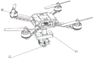
The invention discloses an unmanned aerial vehicle mapping data acquisition device, which relates to the technical field of unmanned aerial vehicle mapping and comprises a positioning plate, wherein a top cover is fixedly connected to the bottom end of the positioning plate, a connecting seat is fixedly connected to the bottom end of the top cover, and a connecting column is fixedly welded to the bottom end surface of the connecting seat. Through the locating plate subassembly structure that sets up, after link and cover frame two connecting bodies pass through the abaculus fixed, in unmanned aerial vehicle survey and drawing in-process, in case meet vibrations, abaculus top will touch with the rubber pad, utilize the spring to play the effect of bradyseism, and the inside linking arm of top cap cooperates the revolving rack of its bottom can effectively promote camera equipment's shooting angle scope, and utilize the spliced pole subassembly structure, through the inside and outside linkage of extension rod to the strut, can make it block the translucent cover from inside to make things convenient for maintenance change camera equipment.
Description
Technical Field
The invention relates to the technical field of unmanned aerial vehicle mapping, in particular to an unmanned aerial vehicle mapping data acquisition device.
Background
The rapid development of economy promotes people to put forward higher requirements on engineering mapping quality, promotes the reform and innovation of related technologies, and the unmanned aerial vehicle remote sensing mapping is generated under the background. As a novel test technology, unmanned aerial vehicle remote sensing mapping has incomparable advantages of other means, relates to contents of a plurality of layers, has obvious advantages for improving the precision and efficiency of mapping work, researches related problems of the unmanned aerial vehicle remote sensing mapping technology applied in engineering mapping, and has very important practical significance for promoting the faster and better development of the unmanned aerial vehicle remote sensing mapping technology.
The invention of publication No. CN214383415U discloses an unmanned aerial vehicle mapping data acquisition device, which can drive camera equipment to rotate by arranging a servo motor and a rotating shaft, adjust the angle of the camera equipment, conveniently detach the camera equipment by arranging a positioning block, a through groove, a push plate, a first pressure spring, a limiting rod and a limiting hole, charge and copy data for the camera equipment, and has the advantage of convenient detachment of a camera by arranging the above structure, thereby solving the problems that most of cameras of the existing unmanned aerial vehicle are fixedly arranged on a rack, inconvenient detachment of the camera and inconvenience in charging and copying the data in the camera; however, the device structure still has some defects in the actual use process, in the aspect of adjusting the shooting angle, the device structure can only be adjusted in the parallel angle, and has certain limitation in the actual use process, and the device structure can be convenient to detach the camera, but can be really and directly installed outside to carry out data mapping, so that the damage of the shooting equipment in the shooting process is easily caused.
Disclosure of Invention
The invention aims to provide an unmanned aerial vehicle mapping data acquisition device which solves the technical problems.
The aim of the invention can be achieved by the following technical scheme:
the unmanned aerial vehicle survey and drawing data acquisition device comprises a positioning plate, wherein a top cover is fixedly connected to the bottom end of the positioning plate, a connecting seat is fixedly connected to the bottom end of the top cover, and a connecting column is fixedly welded to the bottom end surface of the connecting seat;
the locating plate is characterized in that a connecting frame is fixedly welded on the bottom end surface of the locating plate, a groove is formed in the surface of the connecting frame, a limit groove is formed in the inner side of the groove close to the top end of the groove, a spring is fixedly connected to the top end surface of the inner side of the groove, a rubber pad is fixedly connected to the bottom end surface of the spring, a latex pad is fixedly connected to the bottom end surface of the inner side of the groove, an embedded block is embedded in the surface of the groove, and a sleeve frame is sleeved on the outer side surface of the embedded block.
Preferably, the surface of the embedded block is provided with a through hole, the inner side surface of the sleeve frame is provided with an embedded groove at the top end, the side surface of the sleeve frame is provided with a communication hole at the embedded groove, the bottom end surface of the sleeve frame is fixedly welded with a bottom connecting plate, and the top end surface of the positioning plate is fixedly connected with an unmanned aerial vehicle.
Preferably, the top end surface of top cap is equipped with the equipment groove, the bottom surface fixedly connected with installation box of top cap, the bottom surface fixed mounting of top cap has the cover seat, the quantity of cover seat sets up to three, two the surface rotation of cover seat is connected with the connecting rod, another the surface fixed mounting of cover seat has the linkage motor, the surface of connecting rod and the output joint of linkage motor have connecting gear, the surface clamping of connecting rod is fixed with the linkage arm.
Preferably, the bottom surface welded fastening of linkage arm has the revolving rack, the arc surface fixedly connected with screw frame of revolving rack, the both ends welded fastening of revolving rack has half arc frame, the surface of half arc frame is equipped with the movable groove, the bottom surface sliding connection of half arc frame has the cladding frame.
Preferably, the top of cladding frame is located two short side department fixedly connected with anticreep piece, the surface of cladding frame is located long side department fixed mounting and has a cover piece, the surface rotation of cover piece is connected with the lead screw, the surface fixed mounting of cover piece has driving motor, driving motor's output and lead screw fixed connection, the bottom surface fixed mounting of cladding frame has the lug, the side surface of lug is equipped with the fixture block, the side surface of lug is equipped with the screw with fixture block relative position department.
Preferably, the top surface of connecting seat is equipped with the recess, the surface of recess is equipped with the draw-in groove, the surface of recess and draw-in groove relative position department are equipped with the trompil, lug and recess joint, the bottom surface fixedly connected with spliced pole of connecting seat.
Preferably, the bottom surface welded fastening of spliced pole has the linking arm, the inboard of linking arm is equipped with the extension groove, the bottom surface fastening of linking arm is connected with the gear wheel, the side surface fastening of linking arm is connected with the connection pad, the inside fixed mounting of connection pad has the driver, the output fixed mounting of driver has drive gear, the surface of gear wheel is equipped with the track groove, the inside in track groove is equipped with the docking rod, the bottom surface fastening of docking rod has the anticreep festival, the top surface fastening of docking rod has the extension rod, extension rod surface welded fastening has the strut, the surface joint of strut has the translucent cover, the inboard of translucent cover is close to top department and is equipped with the support groove.
The invention has the beneficial effects that:
through the locating plate assembly structure, after the connecting frame and the sleeve frame are fixed through the embedded blocks, once vibration is encountered in the unmanned aerial vehicle mapping process, the top of the embedded blocks are contacted with the rubber pad, and the effect of damping is achieved through the springs;
the shooting angle range of the camera equipment can be effectively improved by matching the linkage arm in the top cover with the rotating frame at the bottom of the top cover;
through utilizing the spliced pole subassembly structure, the cooperation extension rod can make its inside transparent cover of blocking to the inside linkage of strut to make things convenient for maintenance change camera equipment.
Drawings
The invention is further described below with reference to the accompanying drawings.
FIG. 1 is a schematic view of the overall structure of the present invention;
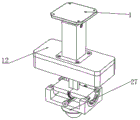
FIG. 2 is a schematic diagram of a mapping data acquisition apparatus of the present invention;
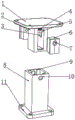
FIG. 3 is a schematic view of a split structure of the locating plate assembly of the present invention;
FIG. 4 is a schematic view showing a disassembled structure of the cap assembly of the present invention;
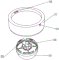
FIG. 5 is a schematic view of the connection base and connection post assembly of the present invention in a disassembled configuration;
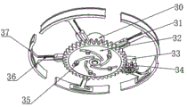
FIG. 6 is a schematic view of a connector assembly according to the present invention.
In the figure: 1. a positioning plate; 2. a connecting frame; 3. a limit groove; 4. a spring; 5. a rubber pad; 6. an insert; 7. a through hole; 8. a sleeve frame; 9. a caulking groove; 10. a communication hole; 11. a bottom connecting plate; 12. a top cover; 13. a mounting box; 14. a sleeve seat; 15. a connecting rod; 16. a linkage motor; 17. a linkage arm; 18. a rotating frame; 19. a screw thread rack; 20. a semi-arc-shaped frame; 21. a movable groove; 22. a cladding frame; 23. an anti-falling block; 24. sleeving blocks; 25. a screw rod; 26. a drive motor; 27. a connecting seat; 28. a clamping groove; 29. opening holes; 30. a connecting column; 31. a connecting arm; 32. a gear plate; 33. a connecting disc; 34. a transmission gear; 35. anti-disengagement; 36. an extension rod; 37. a supporting frame; 38. a transparent cover; 39. a supporting groove; 40. unmanned aerial vehicle.
Detailed Description
The following description of the embodiments of the present invention will be made clearly and completely with reference to the accompanying drawings, in which it is apparent that the embodiments described are only some embodiments of the present invention, but not all embodiments. All other embodiments, which can be made by those skilled in the art based on the embodiments of the invention without making any inventive effort, are intended to be within the scope of the invention.
Referring to fig. 1-6, the invention discloses an unmanned aerial vehicle mapping data acquisition device, which comprises a positioning plate 1, wherein the bottom end of the positioning plate 1 is fixedly connected with a top cover 12, the bottom end of the top cover 12 is fixedly connected with a connecting seat 27, and the bottom end surface of the connecting seat 27 is fixedly welded with a connecting column 30;
the bottom surface welding of locating plate 1 is fixed with link 2, the surface of link 2 is equipped with the fluting, the grooved inboard is close to the top and is equipped with spacing groove 3, the inside top surface fixedly connected with spring 4 of fluting, the bottom surface fixedly connected with rubber pad 5 of spring 4, the inside bottom surface fixedly connected with latex pad of fluting, the grooved surface embedding is connected with abaculus 6, the outside surface cover of abaculus 6 is equipped with and is connected with cover frame 8, in this unmanned aerial vehicle survey and drawing data acquisition device operation, it is when meetting circumstances such as air current, unavoidable meeting can meet circumstances that air current etc. can cause vibrations, the locating plate 1 that is connected with the unmanned aerial vehicle is in the in-process of transmitting vibrations to the cover frame through link 2, every abaculus 6 will receive the compression because of inertia and rubber pad 5, thereby can play certain bradyseism effect, and after the gravity balance, press against latex pad surface, also can cushion certain vibrations;
the surface of the embedded block 6 is provided with a through hole 7, the inner side surface of the sleeve frame 8 is provided with an embedded groove 9 at the top end, the side surface of the sleeve frame 8 is provided with a communication hole 10 at the embedded groove 9, the bottom end surface of the sleeve frame 8 is fixedly welded with a bottom connecting plate 11, the top end surface of the positioning plate 1 is fixedly connected with an unmanned aerial vehicle 40, when the connecting frame 2 and the sleeve frame 8 are assembled and connected, two groups of embedded blocks 6 can be firstly gathered from two sides to the surface of the connecting frame 2, and then the sleeve frame 8 is moved from bottom to top, so that the embedded block 6 is inserted into the embedded groove 9, the through hole 7 is butted with the communication hole 10, and the butt joint can be completed at the moment;
the top end surface of the top cover 12 is provided with an assembly groove, the bottom end surface of the top cover 12 is fixedly connected with a mounting box 13, the bottom end surface of the top cover 12 is fixedly provided with sleeve seats 14, the number of the sleeve seats 14 is three, the surfaces of the two sleeve seats 14 are rotationally connected with connecting rods 15, the surface of the other sleeve seat 14 is fixedly provided with a linkage motor 16, the surfaces of the connecting rods 15 and the output end of the linkage motor 16 are clamped and connected with a connecting gear, the surfaces of the connecting rods 15 are fixedly clamped with a linkage arm 17, when the camera equipment is required to be adjusted towards a parallel shaft, the linkage motor 16 can be started, the connecting rods 15 positioned on the surfaces of the sleeve seats 14 can rotate towards a designated clockwise direction under the linkage action of the connecting gear, and the linkage arm 17 is driven to rotate;
the bottom end surface of the linkage arm 17 is fixedly welded with a rotating frame 18, the arc-shaped surface of the rotating frame 18 is fixedly connected with a threaded frame 19, the two ends of the rotating frame 18 are fixedly welded with a semi-arc-shaped frame 20, the surface of the semi-arc-shaped frame 20 is provided with a movable groove 21, the bottom end surface of the semi-arc-shaped frame 20 is slidably connected with a coating frame 22, when the direction of the camera equipment is required to be adjusted towards the direction of the other parallel axis, a screw rod 25 can be made to rotate in cooperation with the threaded frame 19, and in the process, the semi-arc-shaped frames 20 positioned at the two ends of the rotating frame 18 rotate in cooperation with the radian of the surface of the coating frame 22 and keep stable movement under the action of an anti-falling block 23 and the movable groove 21;
the top end of the cladding frame 22 is fixedly connected with anti-falling blocks 23 at two short side edges, the surface of the cladding frame 22 is fixedly provided with sleeve blocks 24 at a long side edge, the surface of the sleeve blocks 24 is rotationally connected with screw rods 25, the surface of the sleeve blocks 24 is fixedly provided with driving motors 26, the output ends of the driving motors 26 are fixedly connected with the screw rods 25, the bottom end surface of the cladding frame 22 is fixedly provided with protruding blocks, the side surfaces of the protruding blocks are provided with clamping blocks, screw holes are arranged at positions, opposite to the clamping blocks, of the side surfaces of the protruding blocks, when the screw rods 25 are driven to rotate, the driving motors 26 can be electrically started, and then the screw rods 25 are matched with the output ends of the screw rods to rotate towards a designated direction;
the top surface of the connecting seat 27 is provided with a groove, the surface of the groove is provided with a clamping groove 28, an opening 29 is arranged at the position of the surface of the groove opposite to the clamping groove 28, the convex block is clamped with the groove, the bottom surface of the connecting seat 27 is fixedly connected with a connecting column 30, and when the connecting seat 27 is disassembled and assembled, the clamping groove 28 on the surface of the connecting seat 27 is only required to be firstly butted with the clamping block, then the screw holes are matched with the opening 29, and then the connecting seat can be fixed by using bolts;
the bottom surface welded fastening of spliced pole 30 has linking arm 31, the inboard of linking arm 31 is equipped with the extension groove, the bottom surface fastening of linking arm 31 has gear plate 32, the side surface fastening of linking arm 31 has connection pad 33, the inside fixed mounting of connection pad 33 has the driver, the output fixed fastening of driver has drive gear 34, the surface of gear plate 32 is equipped with the orbit groove, the inside in orbit groove is equipped with the docking rod, the bottom surface fastening of docking rod has anticreep festival 35, the top surface fastening of docking rod has extension bar 36, extension bar 36 welded fastening has strut 37, the surface joint of strut 37 has transparent cover 38, the inboard of transparent cover 38 is close to top department and is equipped with strut groove 39, after the camera equipment is installed in transparent cover 38, can automatically controlled start the driver in connection pad 33, then make drive gear 34 drive gear plate 32 rotate, the in-process docking rod also will outwards remove under the restriction effect in orbit groove, simultaneously with the extension bar 36 of its connection will stretch out from linking arm 31, the strut 37 of welding at its surface will support in the transparent cover 38, thereby the easy operation of strut that just, the quick-mounting is convenient, the easy to install and detach, the fast locking of its can be accomplished, the camera equipment is convenient.
The working principle of the invention is as follows: after the camera equipment is installed into the transparent cover 38, the driver in the connecting disc 33 can be started electrically, then the transmission gear 34 drives the gear disc 32 to rotate, in the process, the docking rod can also move outwards under the limiting action of the track groove, simultaneously the extension rod 36 connected with the docking rod extends out of the connecting arm 31, the supporting frame 37 welded on the surface of the docking rod also abuts against the supporting groove 39 of the transparent cover 38, thus the locking of the docking rod is completed, the camera can be quickly assembled and disassembled, time is saved, in the unmanned aerial vehicle mapping data acquisition process, when the camera equipment needs to be made to adjust towards a parallel shaft, the linkage motor 16 can be started, under the linkage action of the connecting gear, the connecting rod 15 positioned on the surface of the sleeve seat 14 can rotate towards the appointed clockwise direction, and drives the linkage arm 17 to rotate, when the camera equipment needs to adjust towards the direction towards the other parallel shaft direction, the screw thread rack 19 can be made to rotate, in the process, the semi-arc-shaped frame 20 positioned at the two ends of the rotating frame 18 can rotate along with the surface of the coating frame 22, and under the action of the anti-falling block 23 and the movable block 21, the air current can also be prevented from contacting with the air cushion pad 1, the vibration pad can be prevented from being contacted with the air current, and the vibration pad can be stably contacted with the air cushion 6, and the vibration pad can be prevented from being met, and the vibration pad can be stably contacted with the vibration pad is contacted with the surface of the air cushion 1, and the vibration pad can be prevented, and the vibration pad can be contacted with the vibration pad is contacted with the vibration pad and the vibration pad is contacted with the vibration pad, and the vibration pad is contacted with the vibration pad.
The foregoing describes one embodiment of the present invention in detail, but the disclosure is only a preferred embodiment of the present invention and should not be construed as limiting the scope of the invention. All equivalent changes and modifications within the scope of the present invention are intended to be covered by the present invention.
Claims (4)
1. Unmanned aerial vehicle survey and drawing data acquisition device, including locating plate (1), its characterized in that: the bottom end of the positioning plate (1) is fixedly connected with a top cover (12), the bottom end of the top cover (12) is fixedly connected with a connecting seat (27), and a connecting column (30) is fixedly welded on the bottom end surface of the connecting seat (27);
the positioning plate is characterized in that a connecting frame (2) is fixedly welded on the bottom end surface of the positioning plate (1), a groove is formed in the surface of the connecting frame (2), a limit groove (3) is formed in the inner side of the groove close to the top end of the groove, a spring (4) is fixedly connected to the top end surface of the inner part of the groove, a rubber pad (5) is fixedly connected to the bottom end surface of the spring (4), a latex pad is fixedly connected to the bottom end surface of the inner part of the groove, an insert (6) is embedded in the surface of the groove, and a sleeve frame (8) is sleeved on the outer side surface of the insert (6);
the top end surface of the top cover (12) is provided with an assembly groove, the bottom end surface of the top cover (12) is fixedly connected with an installation box (13), the bottom end surface of the top cover (12) is fixedly provided with sleeve seats (14), the number of the sleeve seats (14) is three, the surfaces of the two sleeve seats (14) are rotationally connected with connecting rods (15), the other surface of the sleeve seats (14) is fixedly provided with a linkage motor (16), the surfaces of the connecting rods (15) and the output end of the linkage motor (16) are clamped with connecting gears, and the surfaces of the connecting rods (15) are fixedly clamped with linkage arms (17);
the device is characterized in that a rotating frame (18) is fixedly welded on the bottom end surface of the linkage arm (17), a threaded frame (19) is fixedly connected with the arc-shaped surface of the rotating frame (18), a semi-arc-shaped frame (20) is fixedly welded at the two ends of the rotating frame (18), a movable groove (21) is formed in the surface of the semi-arc-shaped frame (20), and a cladding frame (22) is slidably connected with the bottom end surface of the semi-arc-shaped frame (20);
the top of cladding frame (22) is located two short side department fixedly connected with anticreep piece (23), the surface of cladding frame (22) is located long side department fixed mounting and has cover piece (24), the surface rotation of cover piece (24) is connected with lead screw (25), the surface fixed mounting of cover piece (24) has driving motor (26), the output and the lead screw (25) fixed connection of driving motor (26), the bottom surface fixed mounting of cladding frame (22) has the lug, the side surface of lug is equipped with the fixture block, the side surface of lug is equipped with the screw with fixture block relative position department.
2. The unmanned aerial vehicle mapping data acquisition device of claim 1, wherein: the surface of abaculus (6) is equipped with through-hole (7), the inboard surface of cover frame (8) is located top department and is equipped with caulking groove (9), the side surface of cover frame (8) is located caulking groove (9) department and is equipped with intercommunicating pore (10), the bottom surface welding of cover frame (8) is fixed with end connecting plate (11), the top fixed surface of locating plate (1) is connected with unmanned aerial vehicle (40).
3. The unmanned aerial vehicle mapping data acquisition device of claim 1, wherein: the top surface of connecting seat (27) is equipped with the recess, the surface of recess is equipped with draw-in groove (28), the surface of recess and draw-in groove (28) relative position department is equipped with trompil (29), lug and recess joint, the bottom surface fixedly connected with spliced pole (30) of connecting seat (27).
4. The unmanned aerial vehicle mapping data acquisition device of claim 1, wherein: the utility model discloses a solar cell module, including connecting post (30), connecting post, connecting rod, supporting rack, connecting rod and supporting rack is characterized in that bottom surface welded fastening of connecting post (30) is equipped with linking arm (31), the inboard of linking arm (31) is equipped with the extension groove, the bottom surface fastening of linking arm (31) is connected with gear plate (32), the side surface fastening of linking arm (31) is connected with connection pad (33), the inside fixed mounting of connection pad (33) has a driver, the output fixed mounting of driver has drive gear (34), the surface of gear plate (32) is equipped with the track groove, the inside in track groove is equipped with the docking rod, the bottom surface fastening of docking rod is connected with anticreep festival (35), the top surface fastening of docking rod is connected with extension rod (36), extension rod (36) surface welded fastening is equipped with supporting rack (37), the surface joint of supporting rack (37) has transparent cover (38), the inboard of transparent cover (38) is close to top department and is equipped with and props groove (39).
Priority Applications (1)
| Application Number | Priority Date | Filing Date | Title |
|---|---|---|---|
| CN202310278277.XA CN115973473B (en) | 2023-03-21 | 2023-03-21 | Unmanned aerial vehicle survey and drawing data acquisition device |
Applications Claiming Priority (1)
| Application Number | Priority Date | Filing Date | Title |
|---|---|---|---|
| CN202310278277.XA CN115973473B (en) | 2023-03-21 | 2023-03-21 | Unmanned aerial vehicle survey and drawing data acquisition device |
Publications (2)
| Publication Number | Publication Date |
|---|---|
| CN115973473A CN115973473A (en) | 2023-04-18 |
| CN115973473B true CN115973473B (en) | 2023-06-27 |
Family
ID=85976529
Family Applications (1)
| Application Number | Title | Priority Date | Filing Date |
|---|---|---|---|
| CN202310278277.XA Active CN115973473B (en) | 2023-03-21 | 2023-03-21 | Unmanned aerial vehicle survey and drawing data acquisition device |
Country Status (1)
| Country | Link |
|---|---|
| CN (1) | CN115973473B (en) |
Citations (2)
| Publication number | Priority date | Publication date | Assignee | Title |
|---|---|---|---|---|
| CN207991529U (en) * | 2017-05-27 | 2018-10-19 | 广西万维空间科技有限公司 | A kind of unmanned plane surveying and mapping data harvester |
| CN212829121U (en) * | 2020-09-17 | 2021-03-30 | 周晓东 | Data acquisition equipment for channel surveying and mapping |
Family Cites Families (6)
| Publication number | Priority date | Publication date | Assignee | Title |
|---|---|---|---|---|
| CN107250908B (en) * | 2016-01-26 | 2019-04-19 | 深圳市大疆灵眸科技有限公司 | Holder, unmanned vehicle, capture apparatus and movable equipment |
| KR101942832B1 (en) * | 2018-10-19 | 2019-01-30 | (주)뉴비전네트웍스 | Spatial image compensation system for various data editing |
| US10866065B2 (en) * | 2019-03-18 | 2020-12-15 | Daniel Baumgartner | Drone-assisted systems and methods of calculating a ballistic solution for a projectile |
| CN214383415U (en) * | 2021-03-19 | 2021-10-12 | 信小伟 | Unmanned aerial vehicle survey and drawing data acquisition device |
| CN114261527A (en) * | 2022-01-07 | 2022-04-01 | 闫丽丽 | Intelligent unmanned aerial vehicle mapping system |
| CN115806068A (en) * | 2022-12-01 | 2023-03-17 | 江苏城建校建筑规划设计院有限公司 | City is updated with survey and drawing unmanned aerial vehicle device |
-
2023
- 2023-03-21 CN CN202310278277.XA patent/CN115973473B/en active Active
Patent Citations (2)
| Publication number | Priority date | Publication date | Assignee | Title |
|---|---|---|---|---|
| CN207991529U (en) * | 2017-05-27 | 2018-10-19 | 广西万维空间科技有限公司 | A kind of unmanned plane surveying and mapping data harvester |
| CN212829121U (en) * | 2020-09-17 | 2021-03-30 | 周晓东 | Data acquisition equipment for channel surveying and mapping |
Also Published As
| Publication number | Publication date |
|---|---|
| CN115973473A (en) | 2023-04-18 |
Similar Documents
| Publication | Publication Date | Title |
|---|---|---|
| CN108454586B (en) | Protection device convenient for new energy automobile to replace battery pack | |
| CN115973473B (en) | Unmanned aerial vehicle survey and drawing data acquisition device | |
| CN108321259B (en) | Mounting fixture is used in photovoltaic board production | |
| CN214771735U (en) | A tilting disk mechanism for overturning work piece | |
| CN112879733A (en) | Support structure of frame stretching device for inverter processing | |
| CN109159694B (en) | Solar charging pile | |
| CN218057375U (en) | Automatic mud base pile up neatly device of robot | |
| CN217434160U (en) | Rubber joint steel ring positioning mechanism | |
| CN220447918U (en) | Unmanned glider rack under water | |
| CN211075496U (en) | New energy automobile autopilot assists heat abstractor | |
| CN211592221U (en) | Automobile engine tray rack | |
| CN211219682U (en) | Axial fixing device is used in processing of new energy automobile spare part | |
| CN108540062B (en) | Anti-dazzling solar electric vehicle convenient to clean | |
| CN219717322U (en) | Charging pile socket | |
| CN219134051U (en) | Fixing device of vehicle-mounted camera | |
| CN217143626U (en) | New energy vehicle battery pack processing and fixing tool | |
| CN114633793B (en) | Angle-adjustable steering column integrated mounting bracket and passenger car thereof | |
| CN213243658U (en) | Motor core suitable for automobile body stable system | |
| CN220373127U (en) | Clamp for automobile air filter | |
| CN213501822U (en) | Automobile engine support | |
| CN114473432B (en) | Automatic overturning and butt joint heavy-load equipment for assembling aerospace engine | |
| CN219599325U (en) | Positioning and clamping device for processing automobile outer rearview mirror | |
| CN212863157U (en) | Auto-parts gets a robot | |
| CN219503957U (en) | Welding device for automobile mounting bracket | |
| CN219607804U (en) | Circulation geothermal heat energy replacement energy storage device |
Legal Events
| Date | Code | Title | Description |
|---|---|---|---|
| PB01 | Publication | ||
| PB01 | Publication | ||
| SE01 | Entry into force of request for substantive examination | ||
| SE01 | Entry into force of request for substantive examination | ||
| GR01 | Patent grant | ||
| GR01 | Patent grant |