CN115949161A - Intelligent damping device and method for assembly type frame shear wall - Google Patents
Intelligent damping device and method for assembly type frame shear wall Download PDFInfo
- Publication number
- CN115949161A CN115949161A CN202310022298.5A CN202310022298A CN115949161A CN 115949161 A CN115949161 A CN 115949161A CN 202310022298 A CN202310022298 A CN 202310022298A CN 115949161 A CN115949161 A CN 115949161A
- Authority
- CN
- China
- Prior art keywords
- sliding
- seat
- shear wall
- cross beam
- elastic element
- Prior art date
- Legal status (The legal status is an assumption and is not a legal conclusion. Google has not performed a legal analysis and makes no representation as to the accuracy of the status listed.)
- Pending
Links
Images


Landscapes
- Buildings Adapted To Withstand Abnormal External Influences (AREA)
- Vibration Prevention Devices (AREA)
Abstract
The invention discloses an intelligent damping device and method for an assembly type frame shear wall, and belongs to the technical field of assembly type buildings. The intelligent damping device for the assembled frame shear wall comprises a steel structural frame and is characterized in that the steel structural frame comprises a plurality of vertically connected cross beams and vertical beams, sliding seats are arranged on two sides of the upper cross beam and the lower cross beam in a sliding mode, a transverse damping assembly and a first connecting piece are arranged between the two sliding seats on the upper side and between the two sliding seats on the lower side, and a longitudinal damping assembly and a second connecting piece are arranged between the two sliding seats on the upper side and the two sliding seats on the lower side; the invention is convenient to play an effective buffering and anti-seismic effect on the steel structure frame, can reduce the condition that the connection node of the steel structure frame is damaged, and effectively dissipates the seismic energy through the transverse damping assembly and the longitudinal damping assembly so as to improve the anti-seismic property of the whole frame structure and avoid the damage of the shear wall.
Description
Technical Field
The invention relates to the technical field of assembly type buildings, in particular to an intelligent damping device and method for an assembly type frame shear wall.
Background
In order to meet the demand of increasingly diversified building forms in modern society, the building height and span are continuously increased, and therefore, the cooperative development of structures and related design theories is required. The fabricated structure has the advantages of high construction speed, guaranteed component quality, labor saving and the like. The concrete structure types adopted include an assembled frame, a shear wall structure, a prefabricated prestressed structure and the like. In order to adapt to new economic development conditions in China, the assembly type structure is rapidly developed, and related policy documents, industry standards and the like are set by the country to promote the application of the assembly type structure in China.
The existing shear wall is generally arranged in a steel structure frame, and the distortion of the shear wall is limited through a steel structure of the existing shear wall when an earthquake occurs. However, the steel structures are generally fixedly connected by bolts or welded rigid connection, so that the connection node between the frame beam and the frame column is easily damaged, and the whole structure fails; and the steel structure can not reduce the continuous vibration damage of the earthquake aftershock to the building body and the shear wall, and the shear wall is easy to be damaged.
Disclosure of Invention
The invention aims to solve the problems in the prior art and provides an intelligent damping device and method for an assembled frame shear wall.
In order to achieve the purpose, the invention adopts the following technical scheme:
the utility model provides an assembled frame shear force wall intelligence damping device, includes steel structural framework, steel structural framework includes a plurality of perpendicular continuous crossbeams and erects the roof beam, two from top to bottom the both sides of crossbeam are all slided and are provided with the sliding seat, and the upside is two between the sliding seat and the downside is two all be provided with horizontal shock attenuation subassembly and first connecting piece between the sliding seat, the upside is two sliding seat and downside are two be provided with vertical shock attenuation subassembly and second connecting piece between the sliding seat, surround between first connecting piece and the second connecting piece and form the standing groove, be provided with the sponge layer in the standing groove, the sponge in situ is provided with the shear force wall body.
Preferably, vertical damper unit includes first removal seat and the second removal seat of sliding connection on the downside sliding seat of sliding connection on the upside sliding seat respectively, first removal seat and second are removed and are provided with first buffer beam between the seat, two from top to bottom all seted up first spout in the sliding seat, every sliding connection has first slider in the first spout, be provided with first elastic element, two between first slider and the first spout inner wall first slider removes the seat with first removal seat and second respectively and links to each other.
Preferably, the transverse damping assembly comprises a second sliding groove formed in the cross beam, a second sliding block is connected in the second sliding groove in a sliding mode, a second elastic element is arranged between the second sliding block and the inner wall of the second sliding groove, and the second sliding block is connected with the sliding seat.
Preferably, a limiting block is arranged on the second sliding block, a limiting groove is formed in the second sliding groove, the limiting block is connected in the limiting groove in a sliding mode, and a third elastic element is arranged between the inner wall of the limiting groove and the limiting block.
Preferably, the structure of first connecting piece and second connecting piece is the same, all links board and second including the first even board that slides the setting and links to each other the board, the first even board of first connecting piece and second link the board and link to each other with two sliding seats on the same crossbeam respectively, the first even board of second connecting piece and second link the board and move the seat with first removal seat and second respectively and link to each other, first even is connected with the picture peg on the board, the second links to each other to have seted up on the board with picture peg matched with slot.
Preferably, two from top to bottom still be provided with first elastic expansion plate and second elastic expansion plate between the crossbeam, the both ends of first elastic expansion plate remove the seat with the first seat that removes in upper left side and right side below second respectively and rotate and link to each other, the both ends of second elastic expansion plate remove the seat with the first seat that removes in upper right side and left side below second respectively and rotate and link to each other, just the middle part of first elastic expansion plate and second elastic expansion plate is passed through the round pin hub rotation and is connected.
Preferably, the crossbeam is provided with the lug plate, the lug plate is provided with the bull stick in the rotation, erect the roof beam and set firmly on the bull stick, all be provided with the connecting seat on crossbeam and the perpendicular roof beam, two be provided with the second buffer lever between the connecting seat.
Preferably, erect and be provided with the arc rack on the roof beam, rotate through the pivot on the crossbeam and be provided with two drive gears of being connected with the meshing of arc rack, two drive gear is not crossing, sliding connection has the drive rack of being connected with the drive gear meshing on the crossbeam, drive rack offsets with erecting the roof beam activity.
Preferably, the first buffer rod and the second buffer rod are hydraulic dampers or spring assemblies.
The invention also discloses an intelligent damping method for the assembled frame shear wall, which comprises the intelligent damping device for the assembled frame shear wall and further comprises the following steps of:
s1: when the device is used, the prefabricated shear wall body is placed in a placing groove formed by encircling the first connecting piece and the second connecting piece, and a sponge layer is filled between the inner side wall of the placing groove and the shear wall body;
s2: when the steel structure frame is stressed, the vertical beams and the cross beams move relatively, the vertical beams rotate by taking the rotating rods as circle centers, the second buffer rods automatically deform and stretch, the connecting nodes of the steel structure frame are protected from being damaged, and the steel structure frame automatically resets after relative displacement occurs;
s3: when the vertical beam rotates, the arc-shaped rack on the outer side of the vertical beam is meshed with the driving gear on the cross beam, the driving gear rotates and is meshed with the driving rack, the driving rack is relatively moved out of the cross beam, the end part of the driving rack pushes and presses the side wall of the vertical beam after deflection, and the second buffer rod is assisted to push the vertical beam to reset;
s4: and steel structural framework atress is with power to shear force wall body department transmission during vibration, during this period, when receiving the transverse wave influence, two sliding seat relative movement on the same crossbeam, make second elastic element stretched or compression, second elastic element plays the effect of buffering, when receiving the longitudinal wave influence, first removal seat and the second on two upper and lower crossbeams remove seat relative movement, make first buffer beam compression or tensile emergence deformation, reduce the vibration that the shear force wall body received, dissipate the energy of earthquake, with the anti-seismic performance who improves whole steel structural framework.
S5: when transverse waves are generated, the sliding seat slides in the second sliding groove, the second sliding block drives the limiting block to move in the limiting groove, the limiting block is stressed to extrude the third elastic element, the third elastic element deforms, the moving resistance of the third elastic element to the second sliding block is gradually increased along with the continuous stress movement of the limiting block, the energy generated by the transverse waves is consumed until the limiting block cannot continuously move, and the second sliding block is limited in the left-right moving direction; when the longitudinal wave produced, first removal seat and second removed the seat and slide respectively in two upper and lower sliding seats, removed the first slider on the seat and to first elastic element extrusion effort, first elastic element warp, along with removing the first slider displacement grow of seat drive, first elastic element gives the resistance grow gradually of first slider, until first elastic element can't continue to be compressed, first slider received the restriction of first spout this moment, restricted reciprocating of removing the seat.
Compared with the prior art, the invention provides an intelligent damping device and method for an assembled frame shear wall, which have the following beneficial effects:
1. this assembled frame shear force wall intelligence damping device and method through setting up horizontal shock-absorbing component and vertical shock-absorbing component, can dissipate earthquake's energy effectively, and then improves whole frame construction's shock resistance, simple structure, and the shock attenuation is effectual, and the safety in utilization is high, can effectively keep apart external vibration, avoids the shear force wall impaired.
2. This assembled frame shear force wall intelligence damping device and method, through when receiving the transverse wave influence, two sliding seat relative movement, make second elastic element stretched or compress, second elastic element plays the effect of buffering, effectively cushion and weaken the energy that the transverse wave produced, the life of improvement device, and the setting of stopper can be to the second slider on the direction of removal is controlled, reduce the amplitude of oscillation when this steel construction receives transverse vibration power, avoid because sliding seat displacement is too big, lead to the frame construction to become invalid, influence the installation of shear force wall body, and then effectively guarantee the shock attenuation effect of device.
3. This assembled frame shear force wall intelligence damping device and method, through when receiving the longitudinal wave influence, first removal seat and the second on two crossbeams remove the seat relative movement, make first buffer beam compression or tensile emergence deformation, reduce the vibration that the shear force wall body received, the longitudinal wave energy to earthquake dissipates, in order to improve whole steel construction frame's anti-seismic performance, and the setting of first slider can remove the seat and remove the restriction in the sliding seat upper and lower direction, reduce the swing range when this steel construction receives longitudinal vibration power, avoid because remove the distance of removal between the seat too big, lead to the frame construction inefficacy, influence the installation of shear force wall body, effectively improve the shock attenuation effect.
4. The intelligent damping device and method for the assembled frame shear wall have the advantages that when the steel structure frame is stressed, relative movement occurs between the vertical beam and the cross beam, the vertical beam rotates by taking the rotating rod as a circle center, the second buffer rod automatically deforms and stretches, the steel structure frame connecting node is protected from being damaged, and the steel structure frame connecting node automatically resets after relative displacement occurs, the condition that the connecting node of the steel structure frame is damaged is reduced, the structure can still quickly recover the preset use function after damping, the performance goal that the structure can be continuously used without being repaired or slightly repaired after being shaken is achieved, and the practicability is strong.
5. According to the intelligent damping device and method for the assembled frame shear wall, when the vertical beam rotates, the arc-shaped rack on the outer side of the vertical beam is meshed with the driving gear on the cross beam, the driving gear rotates and is meshed with the driving rack, the driving rack is moved out of the cross beam relatively, the end portion of the driving rack pushes and presses the side wall of the vertical beam after deflection, the second buffer rod is assisted, the vertical beam is pushed and reset, and the situation that the stress of a connecting node is too large to deflect and damage can be well avoided under the earthquake condition.
Drawings
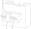
FIG. 1 is a first schematic structural diagram of the present invention;
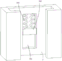
FIG. 2 is a second schematic structural view of the present invention;
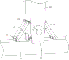
FIG. 3 is a third schematic structural view of the present invention;
FIG. 4 is a schematic structural view of a first connecting member of the present invention;
FIG. 5 is a schematic structural view of a beam of the present invention;
FIG. 6 is a schematic view of the internal structure of the second sliding chute according to the present invention;
FIG. 7 is a schematic view of the external structure of the sliding seat of the present invention;
FIG. 8 is a schematic structural view of the sliding seat and the movable seat of the present invention;
FIG. 9 is a schematic view of the internal structure of the sliding seat of the present invention;
FIG. 10 is a schematic structural view of the steel structural frame of the present invention;
FIG. 11 is a schematic cross-sectional view of the steel frame of the present invention;
fig. 12 is a schematic view of a connection structure of a first elastic expansion plate and a second elastic expansion plate according to the present invention.
In the figure: 1. a steel structural frame; 101. a cross beam; 102. a vertical beam; 2. a sliding seat; 201. a first chute; 202. a first slider; 203. a first elastic element; 3. a first connecting member; 4. a second connecting member; 5. a sponge layer; 6. a shear wall body; 7. a first movable base; 7', a second movable seat; 701. a first buffer rod; 8. a second chute; 801. a second slider; 802. a second elastic element; 9. a first connecting plate; 901. inserting plates; 10. a second connecting plate; 1001. a slot; 11. a first elastic expansion plate; 11', a first elastic expansion plate; 12. a limiting groove; 121. a third elastic element; 122. a limiting block; 13. an ear plate; 131. a rotating rod; 14. a connecting seat; 141. a second buffer rod; 15. an arc-shaped rack; 151. a drive gear; 152. the rack is driven.
Detailed Description
The technical solutions in the embodiments of the present invention will be clearly and completely described below with reference to the drawings in the embodiments of the present invention, and it is obvious that the described embodiments are only a part of the embodiments of the present invention, and not all of the embodiments.
In the description of the present invention, it is to be understood that the terms "upper", "lower", "front", "rear", "left", "right", "top", "bottom", "inner", "outer", and the like, indicate orientations or positional relationships based on the orientations or positional relationships shown in the drawings, are merely for convenience in describing the present invention and simplifying the description, and do not indicate or imply that the device or element being referred to must have a particular orientation, be constructed and operated in a particular orientation, and thus, should not be construed as limiting the present invention.
Example 1:
referring to fig. 1, fig. 2, fig. 3, fig. 5 and fig. 6, an intelligent damping device for an assembled frame shear wall comprises a steel structural frame 1, the steel structural frame 1 comprises a plurality of vertically connected cross beams 101 and vertical beams 102, sliding seats 2 are arranged on two sides of the upper cross beam 101 and two sides of the lower cross beam 101 in a sliding mode, a transverse damping assembly and a first connecting piece 3 are arranged between the two sliding seats 2 on the upper side and between the two sliding seats 2 on the lower side, a longitudinal damping assembly and a second connecting piece 4 are arranged between the two sliding seats 2 on the upper side and the two sliding seats 2 on the lower side, a placing groove is formed between the first connecting piece 3 and the second connecting piece 4 in a surrounding mode, a sponge layer 5 is arranged in the placing groove, and a shear wall body 6 is arranged in the sponge layer 5.
Specifically, when the device is used, the prefabricated shear wall body 6 is placed in a placing groove formed by encircling the first connecting piece 3 and the second connecting piece 4, a sponge layer 5 is filled between the inner side wall of the placing groove and the shear wall body 6, force is transmitted to the shear wall body 6 when the steel structure frame 1 is stressed, the longitudinal damping assembly or the transverse damping assembly works correspondingly to perform damping and buffering on transverse waves or longitudinal waves generated by an earthquake, and earthquake energy is effectively dissipated through the transverse damping assembly and the longitudinal damping assembly to improve the shock resistance of the whole frame structure.
Example 2:
referring to fig. 1, 2, 3, 8 and 9, an intelligent damping device for an assembled frame shear wall is disclosed, in embodiment 1, further, a longitudinal damping assembly includes a first movable seat 7 slidably connected to the upper sliding seat 2 and a second movable seat 7 ' slidably connected to the lower sliding seat 2, a first buffer rod 701 is disposed between the first movable seat 7 and the second movable seat 7 ', first sliding grooves 201 are disposed in the upper sliding seat 2 and the lower sliding seat 2, a first sliding block 202 is slidably connected to each first sliding groove 201, a first elastic element 203 is disposed between the first sliding block 202 and an inner wall of the first sliding groove 201, and the two first sliding blocks 202 are connected to the first movable seat 7 and the second movable seat 7 ', respectively.
Specifically, when longitudinal waves are generated, the device is stressed in the vertical direction, the first movable seat 7 and the second movable seat 7' on the sliding seats 2 of the two cross beams 101 move relatively, so that the first buffer rod 701 is compressed or stretched to deform, vibration of the shear wall body 6 is reduced, and earthquake energy is dissipated, so that the earthquake-resistant performance of the whole steel structure frame 1 is improved, the first elastic element 203 deforms, a certain degree of buffering is achieved on the energy of the longitudinal waves, the first sliding block 202 can limit the movement of the movable seat in the vertical direction in the sliding seats 2, the swing amplitude of the steel structure when longitudinal vibration force is applied to the steel structure is reduced, and the phenomenon that the frame structure fails due to the fact that the moving distance between the movable seats is too large, the installation of the shear wall body 6 is affected, and the shock absorption effect is effectively improved.
Example 3:
referring to fig. 1, 2, 3, 5 and 6, in embodiment 2, the horizontal damping assembly further includes a second sliding groove 8 formed in the cross beam 101, a second sliding block 801 slidably connected to the second sliding groove 8, a second elastic element 802 disposed between the second sliding block 801 and an inner wall of the second sliding groove 8, and the second sliding block 801 connected to the sliding seat 2.
Specifically, when the transverse wave is generated, the device is stressed in the left-right direction, the two sliding seats 2 on the same cross beam 101 move relatively, so that the second elastic element 802 is stretched or compressed, the second elastic element 802 plays a role in buffering, the vibration of the shear wall body 6 is reduced, the energy of the earthquake is dissipated, and the anti-seismic performance of the whole steel structure frame 1 is improved.
Example 4:
referring to fig. 1, fig. 2, fig. 3, fig. 4, fig. 5, fig. 6, and fig. 7, in addition to embodiment 3, a second slider 801 is further provided with a limiting block 122, a limiting groove 12 is formed in the second sliding groove 8, the limiting block 122 is slidably connected in the limiting groove 12, and a third elastic element 121 is disposed between an inner wall of the limiting groove 12 and the limiting block 122.
Specifically, when the shear wave produced, sliding seat 2 slided in second spout 8, second slider 801 drives stopper 122 and removes in spacing groove 12, stopper 122 atress extrudees third elastic element 121, third elastic element 121 warp, move along with stopper 122 continues the atress, third elastic element 121 gives second slider 801's removal resistance grow gradually, consume the energy that the shear wave produced, until stopper 122 can't continue to move, remove second slider 801 and control the orientation and go up the restriction, reduce the amplitude of oscillation when this steel construction received horizontal shaking force, avoid because sliding seat 2 displacement is too big, lead to the frame construction to become invalid, influence shear wall body 6's installation.
Example 5:
referring to fig. 1, 2, 3 and 4, an intelligent damping device for an assembled frame shear wall is provided, in embodiment 1, further, a first connecting member 3 and a second connecting member 4 have the same structure and each include a first connecting plate 9 and a second connecting plate 10, the first connecting plate 9 and the second connecting plate 10 of the first connecting member 3 are respectively connected to two sliding seats 2 on the same cross beam 101, the first connecting plate 9 and the second connecting plate 10 of the second connecting member 4 are respectively connected to a first movable seat 7 and a second movable seat 7', the first connecting plate 9 is connected to an insert plate 901, and the second connecting plate 10 is provided with a slot 1001 matched with the insert plate 901.
Specifically, when a longitudinal wave is generated, the distance between the second connecting members 4 is changed, so that the distance between the first movable seat 7 and the second movable seat 7 'is relatively moved, the first connecting plate 9 and the second connecting plate 10 on the first movable seat 7 and the second movable seat 7' are relatively slid, and in the process, the inserting plate 901 is slid in the slot 1001, so that the stability of the up-and-down movement of the movable seats is improved; when a transverse wave is generated, the two sliding seats 2 on the same transverse beam 101 move relatively, the distance between the first connecting pieces 3 changes, so that the first connecting plates 9 and the second connecting plates 10 on the two sliding seats 2 slide relatively, in the process, the inserting plate 901 slides in the slot 1001, and the stability of the left and right movement of the sliding seats 2 is improved.
Example 6:
referring to fig. 1 and 12, an intelligent damping device for a fabricated frame shear wall is further provided in embodiment 3, wherein a first elastic expansion plate 11 and a second elastic expansion plate 11 ' are further disposed between the upper and lower cross beams 101, two ends of the first elastic expansion plate 11 are respectively rotatably connected to the upper left first movable seat 7 and the lower right second movable seat 7 ', two ends of the second elastic expansion plate 11 ' are respectively rotatably connected to the upper right first movable seat 7 and the lower left second movable seat 7 ', and middle portions of the first elastic expansion plate 11 and the second elastic expansion plate 11 ' are rotatably connected by a pin.
Specifically, by arranging the first elastic expansion plate 11 and the second elastic expansion plate 11 ' which are crossed between the moving seats on the two beams 101, when longitudinal waves or transverse waves are generated and the longitudinal damping assembly or the transverse damping assembly works, the first elastic expansion plate 11 and the second elastic expansion plate 11 ' automatically stretch or contract, and automatically rotate around a pin shaft between the first elastic expansion plate 11 and the second elastic expansion plate 11 ' in the process, so that the damping effect is further achieved, the transverse waves or the longitudinal waves generated by an earthquake are further damped and buffered, the energy of the earthquake is effectively dissipated, and the anti-seismic performance of the whole frame structure is improved.
Example 7:
referring to fig. 1, 2, 3, 10 and 11, in example 6, further, an ear plate 13 is disposed on the cross beam 101, a rotating rod 131 is rotatably disposed on the ear plate 13, the vertical beam 102 is fixedly disposed on the rotating rod 131, the cross beam 101 and the vertical beam 102 are both provided with connecting seats 14, and a second buffer rod 141 is disposed between the two connecting seats 14.
Specifically, during steel frame 1 atress, relative movement takes place between perpendicular roof beam 102 and the crossbeam 101, perpendicular roof beam 102 uses bull stick 131 to take place to rotate as the centre of a circle, the automatic flexible deformation of second buffer beam 141 of both sides, protection steel frame 1 connected node does not receive the damage, and can automatic re-setting after taking place relative displacement, be convenient for play effectual buffering antidetonation effect to steel frame 1, make flexible connection replace bolted connection or welded rigid connection mode, the condition of destruction appears in steel frame 1's connected node can be reduced, can realize that the structure possesses the ability that still can resume its predetermined service function fast after the cushioning effect, realize that the structure need not restore after shaking or add slightly and restore the performance target that just continues to use, therefore, the clothes hanger is strong in practicability.
Example 8:
referring to fig. 1, 2, 3, 10 and 11, in example 7, further, an arc-shaped rack 15 is disposed on the vertical beam 102, two driving gears 151 meshed with the arc-shaped rack 15 are rotatably disposed on the cross beam 101 through a rotating shaft, the two driving gears 151 are not intersected, a driving rack 152 meshed with the driving gears 151 is slidably connected to the cross beam 101, and the driving rack 152 movably abuts against the vertical beam 102.
Specifically, when the steel structure frame 1 is stressed, the vertical beam 102 and the cross beam 101 move relatively, when the vertical beam 102 rotates, the arc-shaped rack 15 on the outer side of the vertical beam 102 is meshed with the driving gear 151 on the cross beam 101, the driving gear 151 rotates and is meshed with the driving rack 152, the driving rack 152 moves out of the cross beam 101 relatively, the end portion of the driving rack 152 pushes and presses the side wall of the vertical beam 102 after deflection, the auxiliary second buffer rod 141 pushes the vertical beam 102 to reset rapidly, and damage caused by overlarge deflection of the stress at the connecting node can be well avoided under the earthquake condition.
Example 9:
referring to fig. 1, 2, 3, 10 and 11, in an assembled frame shear wall intelligent damping device, based on embodiment 8, further, a first buffer rod 701 and a second buffer rod 141 are hydraulic dampers or spring assemblies.
Specifically, the buffer rod is set to be a hydraulic damper or a spring assembly, so that energy vibration generated in an earthquake is buffered and consumed, the shock resistance of the whole frame structure is improved, and the shear wall body 6 is prevented from being damaged.
The invention also discloses an intelligent damping method for the assembled frame shear wall, which comprises the intelligent damping device for the assembled frame shear wall and further comprises the following steps of:
s1: when the device is used, the prefabricated shear wall body 6 is placed in a placing groove formed by the first connecting piece 3 and the second connecting piece 4 in a surrounding mode, and a sponge layer 5 is filled between the inner side wall of the placing groove and the shear wall body 6;
s2: when the steel structure frame 1 is stressed, the vertical beam 102 and the cross beam 101 move relatively, the vertical beam 102 rotates by taking the rotating rod 131 as a circle center, the second buffer rod 141 deforms and stretches automatically, the connecting node of the steel structure frame 1 is protected from being damaged, and the steel structure frame 1 automatically resets after relative displacement occurs;
s3: when the vertical beam 102 rotates, the arc-shaped rack 15 on the outer side of the vertical beam 102 is meshed with the driving gear 151 on the cross beam 101, the driving gear 151 rotates and is meshed with the driving rack 152, so that the driving rack 152 relatively moves out of the cross beam 101, the end part of the driving rack 152 pushes the deflected side wall of the vertical beam 102, and the second buffer rod 141 is assisted to push the vertical beam 102 to reset;
s4: and steel structural framework 1 will transmit power to shear force wall body 6 department when the atress vibrates, during this period, when receiving the transverse wave influence, two sliding seat 2 relative movement on same crossbeam 101 make second elastic component 802 stretched or compress, second elastic component 802 plays the effect of buffering, when receiving the longitudinal wave influence, first removal seat 7 and the second on two upper and lower crossbeams 101 remove seat 7' relative movement, make first buffer bar 701 compression or tensile emergence deformation, reduce the vibration that shear force wall body 6 received, dissipate the energy of earthquake, with the anti-seismic performance who improves whole steel structural framework 1.
S5: when a transverse wave is generated, the sliding seat 2 slides in the second sliding groove 8, the second sliding block 801 drives the limiting block 122 to move in the limiting groove 12, the limiting block 122 is stressed to extrude the third elastic element 121, the third elastic element 121 deforms, the movement resistance given to the second sliding block 801 by the third elastic element 121 is gradually increased along with the continuous stress movement of the limiting block 122, the energy generated by the transverse wave is consumed until the limiting block 122 cannot continuously move, the second sliding block 801 is limited in the left-right movement direction, and the phenomenon that the installation of the shear wall body 6 is influenced due to the fact that the frame structure fails due to the fact that the sliding seat 2 moves too far is avoided; when longitudinal waves are generated, the first movable seat 7 and the second movable seat 7' respectively slide in the upper sliding seat 2 and the lower sliding seat 2, the first sliding block 202 on the movable seat extrudes acting force on the first elastic element 203, the first elastic element 203 deforms, the moving distance of the first sliding block 202 is increased along with the movement of the movable seat, the resistance of the first elastic element 203 to the first sliding block 202 is gradually increased until the first elastic element 203 cannot be continuously compressed, at the moment, the first sliding block 202 is limited by the first sliding groove 201, the up-and-down movement of the movable seat is limited, the phenomenon that the frame structure fails due to the fact that the moving distance between the movable seats is too large, the installation of the shear wall body 6 is affected is avoided, the damping effect is effectively improved, and the installation and use effects of the shear wall body 6 are guaranteed.
According to the invention, through arranging the transverse damping component and the longitudinal damping component, the energy of earthquake can be effectively dissipated, so that the earthquake resistance of the whole frame structure is improved, the structure is simple, the damping effect is good, the use safety is high, external vibration can be effectively isolated, the damage of a shear wall is avoided, and the practicability is strong.
The above description is only for the preferred embodiment of the present invention, but the scope of the present invention is not limited thereto, and any person skilled in the art should be considered as the technical solutions and the inventive concepts of the present invention within the technical scope of the present invention.
Claims (10)
1. The utility model provides an assembled frame shear force wall intelligence damping device, includes steel structural framework (1), its characterized in that, steel structural framework (1) includes a plurality of perpendicular continuous crossbeam (101) and erects roof beam (102), two from top to bottom the both sides of crossbeam (101) all slide and be provided with sliding seat (2), and the upside is two between sliding seat (2) and the downside is two all be provided with horizontal shock attenuation subassembly and first connecting piece (3), upside two between sliding seat (2) and downside are two be provided with vertical shock attenuation subassembly and second connecting piece (4) between sliding seat (2), enclose between first connecting piece (3) and the second connecting piece (4) and form the standing groove, be provided with sponge layer (5) in the standing groove, be provided with shear force wall body (6) in sponge layer (5).
2. The assembly type frame shear wall intelligent shock absorption device according to claim 1, wherein the longitudinal shock absorption components respectively comprise a first movable seat (7) slidably connected to the upper sliding seat (2) and a second movable seat (7 ') slidably connected to the lower sliding seat (2), a first buffer rod (701) is arranged between the first movable seat (7) and the second movable seat (7 '), a first sliding chute (201) is formed in each of the upper sliding seat and the lower sliding seat (2), a first sliding block (202) is slidably connected in each first sliding chute (201), a first elastic element (203) is arranged between each first sliding block (202) and the inner wall of each first sliding chute (201), and the two first sliding blocks (202) are respectively connected with the first movable seat (7) and the second movable seat (7 ').
3. The assembly type frame shear wall intelligent damping device according to claim 2, wherein the transverse damping assembly comprises a second sliding groove (8) formed in the cross beam (101), a second sliding block (801) is connected in the second sliding groove (8) in a sliding mode, a second elastic element (802) is arranged between the second sliding block (801) and the inner wall of the second sliding groove (8), and the second sliding block (801) is connected with the sliding seat (2).
4. The assembly type frame shear wall intelligent damping device according to claim 3, wherein a limiting block (122) is arranged on the second sliding block (801), a limiting groove (12) is formed in the second sliding groove (8), the limiting block (122) is slidably connected in the limiting groove (12), and a third elastic element (121) is arranged between the inner wall of the limiting groove (12) and the limiting block (122).
5. The assembly type frame shear wall intelligent damping device according to claim 1, wherein the first connecting piece (3) and the second connecting piece (4) are identical in structure and respectively comprise a first connecting plate (9) and a second connecting plate (10) which are arranged in a sliding mode, the first connecting plate (9) and the second connecting plate (10) of the first connecting piece (3) are respectively connected with the two sliding seats (2) on the same cross beam (101), the first connecting plate (9) and the second connecting plate (10) of the second connecting piece (4) are respectively connected with the first movable seat (7) and the second movable seat (7'), the first connecting plate (9) is connected with an inserting plate (901), and the second connecting plate (10) is provided with a slot (1001) matched with the inserting plate (901).
6. The assembly type frame shear wall intelligent damping device according to claim 3, wherein a first elastic expansion plate (11) and a second elastic expansion plate (11 ') are further arranged between the upper cross beam (101) and the lower cross beam (101), two ends of the first elastic expansion plate (11) are respectively rotatably connected with the upper left first movable seat (7) and the lower right second movable seat (7 '), two ends of the second elastic expansion plate (11 ') are respectively rotatably connected with the upper right first movable seat (7) and the lower left second movable seat (7 '), and the middle parts of the first elastic expansion plate (11) and the second elastic expansion plate (11 ') are rotatably connected through a pin shaft.
7. The intelligent damping device for the fabricated frame shear wall according to claim 6, wherein the cross beam (101) is provided with an ear plate (13), the ear plate (13) is provided with a rotating rod (131) in a rotating manner, the vertical beam (102) is fixedly arranged on the rotating rod (131), the cross beam (101) and the vertical beam (102) are provided with connecting seats (14), and a second buffer rod (141) is arranged between the two connecting seats (14).
8. The intelligent damping device for the fabricated frame shear wall according to claim 7, wherein the vertical beam (102) is provided with an arc-shaped rack (15), the cross beam (101) is rotatably provided with two driving gears (151) meshed and connected with the arc-shaped rack (15) through a rotating shaft, the two driving gears (151) are not intersected, the cross beam (101) is slidably connected with a driving rack (152) meshed and connected with the driving gears (151), and the driving rack (152) is movably abutted against the vertical beam (102).
9. The fabricated frame shear wall intelligent shock-absorbing device according to claim 8, wherein the first buffer rod (701) and the second buffer rod (141) are hydraulic dampers or spring assemblies.
10. An intelligent damping method for a fabricated frame shear wall, which is characterized by comprising the intelligent damping device for the fabricated frame shear wall as claimed in any one of claims 1 to 9, and further comprising the following steps:
s1: when the device is used, the prefabricated shear wall body (6) is placed in a placing groove formed by the first connecting piece (3) and the second connecting piece (4) in a surrounding mode, and a sponge layer (5) is filled between the inner side wall of the placing groove and the shear wall body (6);
s2: when the steel structure frame (1) is stressed, the vertical beam (102) and the cross beam (101) move relatively, the vertical beam (102) rotates by taking the rotating rod (131) as a circle center, the second buffer rod (141) deforms and stretches automatically, the connecting node of the steel structure frame (1) is protected from being damaged, and the steel structure frame automatically resets after relative displacement occurs;
s3: when the vertical beam (102) rotates, the arc-shaped rack (15) on the outer side of the vertical beam (102) is meshed with the driving gear (151) on the cross beam (101), the driving gear (151) rotates and is meshed with the driving rack (152), the driving rack (152) is relatively moved out of the cross beam (101), the end part of the driving rack (152) pushes and presses the deflected side wall of the vertical beam (102), and the second buffer rod (141) is assisted to push the vertical beam (102) to reset;
s4: and the steel structure frame (1) transmits force to the shear wall body (6) when stressed and vibrated, during the period, when influenced by transverse waves, the two sliding seats (2) on the same cross beam (101) move relatively to enable the second elastic element (802) to be stretched or compressed, the second elastic element (802) plays a role in buffering, when influenced by longitudinal waves, the first movable seat (7) and the second movable seat (7') on the upper cross beam (101) and the lower cross beam (101) move relatively to enable the first buffer rod (701) to be compressed or stretched to deform, the vibration of the shear wall body (6) is reduced, the energy of earthquake is dissipated, and the earthquake resistance performance of the whole steel structure frame (1) is improved.
S5: when transverse waves are generated, the sliding seat (2) slides in the second sliding groove (8), the second sliding block (801) drives the limiting block (122) to move in the limiting groove (12), the limiting block (122) is stressed to extrude the third elastic element (121), the third elastic element (121) deforms, and along with the continuous stress movement of the limiting block (122), the movement resistance given to the second sliding block (801) by the third elastic element (121) is gradually increased, energy generated by the transverse waves is consumed until the limiting block (122) cannot move continuously, and the second sliding block (801) is limited in the left-right movement direction; when longitudinal waves are generated, the first movable seat (7) and the second movable seat (7') slide in the upper sliding seat (2) and the lower sliding seat (2) respectively, the first sliding block (202) on the movable seats extrudes acting force on the first elastic element (203), the first elastic element (203) deforms, the moving distance of the first sliding block (202) is increased along with the driving of the movable seats, the resistance force given to the first sliding block (202) by the first elastic element (203) is gradually increased until the first elastic element (203) cannot be compressed continuously, and at the moment, the first sliding block (202) is limited by the first sliding groove (201) to limit the up-and-down movement of the movable seats.
Priority Applications (1)
| Application Number | Priority Date | Filing Date | Title |
|---|---|---|---|
| CN202310022298.5A CN115949161A (en) | 2023-01-07 | 2023-01-07 | Intelligent damping device and method for assembly type frame shear wall |
Applications Claiming Priority (1)
| Application Number | Priority Date | Filing Date | Title |
|---|---|---|---|
| CN202310022298.5A CN115949161A (en) | 2023-01-07 | 2023-01-07 | Intelligent damping device and method for assembly type frame shear wall |
Publications (1)
| Publication Number | Publication Date |
|---|---|
| CN115949161A true CN115949161A (en) | 2023-04-11 |
Family
ID=87296625
Family Applications (1)
| Application Number | Title | Priority Date | Filing Date |
|---|---|---|---|
| CN202310022298.5A Pending CN115949161A (en) | 2023-01-07 | 2023-01-07 | Intelligent damping device and method for assembly type frame shear wall |
Country Status (1)
| Country | Link |
|---|---|
| CN (1) | CN115949161A (en) |
Cited By (3)
| Publication number | Priority date | Publication date | Assignee | Title |
|---|---|---|---|---|
| CN117605148A (en) * | 2024-01-22 | 2024-02-27 | 成都中品建设工程有限公司 | Green building and construction method thereof |
| CN117702942A (en) * | 2023-12-26 | 2024-03-15 | 杭萧钢构(山东)有限公司 | Prefabricated assembly type anti-seismic steel structure and anti-seismic method thereof |
| CN117888628A (en) * | 2024-03-14 | 2024-04-16 | 南安市装备制造业技术研究院 | Building steel structure with anti-seismic function |
-
2023
- 2023-01-07 CN CN202310022298.5A patent/CN115949161A/en active Pending
Cited By (5)
| Publication number | Priority date | Publication date | Assignee | Title |
|---|---|---|---|---|
| CN117702942A (en) * | 2023-12-26 | 2024-03-15 | 杭萧钢构(山东)有限公司 | Prefabricated assembly type anti-seismic steel structure and anti-seismic method thereof |
| CN117605148A (en) * | 2024-01-22 | 2024-02-27 | 成都中品建设工程有限公司 | Green building and construction method thereof |
| CN117605148B (en) * | 2024-01-22 | 2024-04-30 | 成都中品建设工程有限公司 | Green building and construction method thereof |
| CN117888628A (en) * | 2024-03-14 | 2024-04-16 | 南安市装备制造业技术研究院 | Building steel structure with anti-seismic function |
| CN117888628B (en) * | 2024-03-14 | 2024-05-28 | 南安市装备制造业技术研究院 | Building steel structure with anti-seismic function |
Similar Documents
| Publication | Publication Date | Title |
|---|---|---|
| CN115949161A (en) | Intelligent damping device and method for assembly type frame shear wall | |
| CN112031504B (en) | Lever type inertia capacity synergistic shape memory alloy self-resetting structure system | |
| CN211548032U (en) | Anti-seismic fabricated building frame structure | |
| CN111827505B (en) | Shape memory alloy damper | |
| CN108301676B (en) | Multi-dimensional combined type bearing type anti-seismic joint device | |
| CN114775410A (en) | Limiting self-resetting railway swinging hollow pier with built-in corrugated web damper | |
| CN109372283B (en) | Building wall with antidetonation reinforced performance | |
| CN210164081U (en) | Assembled building shock-absorbing structure | |
| CN116770978B (en) | Antidetonation steel construction | |
| CN219772936U (en) | Assembled building foundation bottom reinforcing apparatus | |
| CN211548196U (en) | Steel plate concrete shear wall with strong edge member | |
| CN113089866A (en) | Civil engineering shock attenuation component | |
| CN110924551B (en) | Friction sliding bearing seat vibration reduction structure between ground and building | |
| CN113235743A (en) | High-rise steel structure self-adaptive damping device and using method thereof | |
| CN115110666B (en) | Energy dissipation and shock absorption connection structure of connecting beam | |
| CN215857194U (en) | Shock attenuation stop device | |
| CN113685068B (en) | Frame upper door type steel frame factory building capable of resisting seismic wave impact | |
| CN220686360U (en) | Building structure seam structure | |
| CN213805974U (en) | Shear wall structure for building construction | |
| CN216360805U (en) | Shock attenuation frame beam column node | |
| CN215978581U (en) | Novel building engineering frame roof beam is consolidated device | |
| CN219219451U (en) | Wall body shock-resistant structure is built in room | |
| CN220888960U (en) | Shock-absorbing base for joint connection of building steel structure | |
| CN219840205U (en) | Shock-resistant connecting rod piece | |
| CN215330651U (en) | Effectual steel structure support of antidetonation |
Legal Events
| Date | Code | Title | Description |
|---|---|---|---|
| PB01 | Publication | ||
| PB01 | Publication | ||
| SE01 | Entry into force of request for substantive examination | ||
| SE01 | Entry into force of request for substantive examination |