CN115947274B - Steel platform suitable for long and narrow deep foundation pit excavation construction - Google Patents
Steel platform suitable for long and narrow deep foundation pit excavation construction Download PDFInfo
- Publication number
- CN115947274B CN115947274B CN202310239643.0A CN202310239643A CN115947274B CN 115947274 B CN115947274 B CN 115947274B CN 202310239643 A CN202310239643 A CN 202310239643A CN 115947274 B CN115947274 B CN 115947274B
- Authority
- CN
- China
- Prior art keywords
- construction
- foundation pit
- hanging basket
- positioning
- long
- Prior art date
- Legal status (The legal status is an assumption and is not a legal conclusion. Google has not performed a legal analysis and makes no representation as to the accuracy of the status listed.)
- Active
Links
Images

Classifications
-
- Y—GENERAL TAGGING OF NEW TECHNOLOGICAL DEVELOPMENTS; GENERAL TAGGING OF CROSS-SECTIONAL TECHNOLOGIES SPANNING OVER SEVERAL SECTIONS OF THE IPC; TECHNICAL SUBJECTS COVERED BY FORMER USPC CROSS-REFERENCE ART COLLECTIONS [XRACs] AND DIGESTS
- Y02—TECHNOLOGIES OR APPLICATIONS FOR MITIGATION OR ADAPTATION AGAINST CLIMATE CHANGE
- Y02E—REDUCTION OF GREENHOUSE GAS [GHG] EMISSIONS, RELATED TO ENERGY GENERATION, TRANSMISSION OR DISTRIBUTION
- Y02E10/00—Energy generation through renewable energy sources
- Y02E10/20—Hydro energy
Landscapes
- Conveying And Assembling Of Building Elements In Situ (AREA)
Abstract
The invention relates to the technical field of foundation pit construction, in particular to a steel platform suitable for long and narrow deep foundation pit excavation construction, which comprises a door-shaped bracket, a lifting mechanism and a construction hanging basket; the vertical rods at two sides of the door-shaped support are erected on the side wall of the deep foundation pit, and the lifting mechanism is fixedly arranged on a cross beam of the door-shaped support; the lifting mechanism is connected to the construction hanging basket through an internal steel wire rope, the construction hanging basket moves up and down in the door-type support, supporting legs are arranged on the vertical rods in a sliding mode, the supporting legs and the vertical rods can be locked with each other, and the supporting legs are pressed on the ground on two sides of the foundation pit and used for supporting the whole steel platform. The steel platform of construction of this application design not only can transport small-size construction equipment, material and constructor, still is applicable to simultaneously that the construction equipment that the size is bigger also can transport and carry out construction operation in long and narrow deep basal pit, and then can improve long and narrow deep basal pit excavation construction's efficiency.
Description
Technical Field
The invention relates to the technical field of foundation pit construction, in particular to a steel platform suitable for long and narrow deep foundation pit excavation construction, and an auxiliary construction system for long and narrow deep foundation pit excavation by using the same
Background
Deep foundation pit refers to a foundation pit with an excavation depth of not less than 5m or not more than 5m, but complicated geological conditions, surrounding environment and underground pipelines, or affecting the safety of adjacent buildings.
For example, in the construction of light rail projects in some cities, because the light rail is often arranged in a region with dense population buildings, adjacent buildings or roads are arranged around a construction site, multiple paths of vehicles are narrow, and a construction platform is arranged around the construction site without space, so that a temporary steel platform is required to be constructed at the top of a foundation pit for avoiding construction vehicles and handling material turnover during construction of a structure.
The existing steel platform can transfer heavy construction equipment and materials, but the existing steel platform cannot transfer large-size drain pipes, culverts or mini-excavators with longer lengths, so that the application range of the existing steel platform in a long and narrow deep foundation pit is limited.
Accordingly, the application provides a steel platform suitable for long and narrow deep foundation pit excavation construction.
Disclosure of Invention
The invention relates to a steel platform suitable for long and narrow deep foundation pit excavation construction.
The technical problems to be solved are as follows: on narrow construction sites in cities and the like, how to effectively construct long and narrow deep foundation pits provides construction assistance.
In order to solve the technical problems, the invention discloses a steel platform suitable for long and narrow deep foundation pit excavation construction, which adopts the following scheme.
A steel platform suitable for long and narrow deep foundation pit excavation construction comprises a door-shaped bracket, a lifting mechanism and a construction hanging basket; the vertical rods at two sides of the door-shaped support are erected on the side wall of the deep foundation pit, and the lifting mechanism is fixedly arranged on a cross beam of the door-shaped support; the lifting mechanism is connected to the construction hanging basket through an internal steel wire rope, the construction hanging basket moves up and down in the door-type support, supporting legs are arranged on the vertical rods in a sliding mode, the supporting legs and the vertical rods can be locked with each other, and the supporting legs are pressed on the ground on two sides of the foundation pit and used for supporting the whole steel platform.
Preferably, the front baffle and the rear baffle of the construction hanging basket can be flattened to be in a horizontal state for hoisting large-size construction equipment into the long and narrow deep foundation pit for construction operation.
Preferably, the front and back side baffles of the construction hanging basket are rotatably mounted on the bottom plate of the construction hanging basket through a rotating shaft, torsion springs are sleeved on the rotating shaft, the upper ends of the outer surfaces of the front and back side baffles are connected with one ends of tensioning ropes, and the other ends of the tensioning ropes penetrate through pulley assemblies arranged on the lower portion of the bottom plate to be connected with connecting members.
Preferably, the construction hanging basket can be fixed on the vertical rod through positioning members arranged on the baffle plates at the left side and the right side; the locating component includes sliding block, locating piece, location inserted bar and locking bolt, all fixed mounting has the sliding block on the left and right sides baffle of construction hanging flower basket, the sliding tray has been seted up on the lateral wall that montant and construction hanging flower basket laminated, the sliding block slides from top to bottom in the sliding tray, the constant head tank has been seted up to the sliding block surface, and the sliding in the constant head tank is provided with the locating piece, the fixed surface of locating piece is provided with a plurality of location inserted bars, a plurality of location jacks have been seted up on the vertical direction on the sliding tray lateral wall, a plurality of location inserted bar and wherein several location jacks slide each other and peg graft and align, all threaded connection has the locking bolt on the left and right sides baffle of construction hanging flower basket, and the terminal surface of locking bolt passes the surface rotation of sliding block and locating piece and be connected.
Preferably, the end part of the steel wire rope is detachably connected with the construction hanging basket through a connecting component; the connecting component comprises a threaded column, a T-shaped inserted rod and a positioning screw rod, wherein a threaded hole is formed in the bottom plate, the threaded column is connected with the threaded hole, the upper end face of the threaded column is rotationally connected with the end part of the steel wire rope, the bottom plate is provided with inserted holes in a penetrating mode, the inserted holes are symmetrically formed in the front side and the rear side of the threaded hole, the T-shaped inserted rod is slidably inserted in the inserted holes, the diameter of a disc at the upper end of the T-shaped inserted rod is larger than that of the inserted holes, a threaded slotted hole is formed in the upper portion of the T-shaped inserted rod in a penetrating mode, the threaded slotted hole is detachably connected with the threaded column, the lower end portion of the T-shaped inserted rod penetrates through the inserted holes and is rotationally connected with the tensioning rope, and the positioning screw rod is fixedly arranged on the inner surface of the baffle on the left side and the right side, and the positioning screw rod is detachably connected with the T-shaped inserted rod.
Preferably, the front and rear outer surfaces of the vertical rods on two sides are provided with guide sliding grooves with T-shaped cross sections, the supporting legs are slidably arranged in the guide sliding grooves through guide blocks with T-shaped cross sections, the lower surfaces of the supporting legs are rotatably provided with roller members, and the supporting legs are internally provided with balancing weights.
Preferably, the outer wall of the steel wire rope is wrapped with a protective layer, the height of the protective layer is higher than that of the construction hanging basket, and the protective layer is made of a silicon rubber material or an elastic alloy material.
Compared with the prior art, the invention has the beneficial effects that: according to the invention, the supporting legs on the left vertical rod and the right vertical rod of the door-shaped bracket are supported on two sides of the foundation pit, the vertical rods are used as frame structural members on one hand, and are used as guide rail tracks to be inserted into the foundation pit on the other hand, and then the lifting machine controls the lifting basket to move up and down along the vertical rods.
The height of supporting leg can be adjusted, adapts to the inconsistent condition of foundation ditch both sides ground height on the one hand, and on the other hand is convenient for adjust the height of door-type support.
This application is through setting up the construction hanging basket of liftable on the door type support, and the construction hanging basket of liftable can enough transform to expand and be the dull and stereotyped form and deposit handling to the construction equipment of jumbo size, can fold simultaneously again and be basket form and carry out handling to small-size construction equipment, material and constructor in the deep basal pit, thereby make the steel platform of the construction of this application design not only can transport small-size construction equipment, material and constructor, still be applicable to the construction equipment that the size is bigger simultaneously and also can transport and carry out construction operation in the long and narrow deep basal pit, and then can improve the efficiency of long and narrow deep basal pit excavation construction.
Meanwhile, the invention also provides an auxiliary construction system for the long and narrow deep foundation pit excavation, which is applied to the steel platform for the long and narrow deep foundation pit excavation construction.
The construction system comprises support structures arranged on the ground at two sides of the foundation pit and a construction platform arranged in the foundation pit, wherein the support structures are used for assisting the construction of the foundation pit; the construction platform is a steel platform for long and narrow deep foundation pit excavation construction;
the support structure is fixed on the ground along the edge of the foundation pit, and the support legs of the steel platform are mounted on the support structure.
Preferably, the support structure comprises a track parallel to the extending direction of the foundation pit, and the support legs are arranged on the track and move along the track; both sides of foundation ditch all are provided with bearing structure, and all set up the track on the bearing structure, and two tracks are parallel to each other and interval keeps unanimous.
First, in order to provide a construction platform, i.e. the steel platform described above, support structures are provided on both sides of the foundation pit, and then the left and right support legs of the steel platform are provided to the support structures. Simultaneously bearing structure sets up along the edge of foundation ditch, when needs steel platform remove, and steel platform can switch the position on bearing structure, and steel platform can remove in the foundation ditch.
Drawings
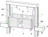
FIG. 1 is a schematic diagram of the structure of the present invention;
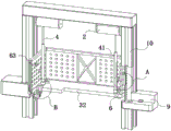
FIG. 2 is a cross-sectional view of the construction basket of the present invention;
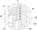
FIG. 3 is an enlarged view of a portion of FIG. 2A in accordance with the present invention;
fig. 4 is an enlarged view of a portion of fig. 2B in accordance with the present invention.
In the figure: 1. a door-shaped bracket; 10. a vertical rod; 101. a sliding groove; 102. positioning the jack; 103. a guide chute; 2. a lifting mechanism; 3. constructing a hanging basket; 31. a baffle; 32. a bottom plate; 321. a threaded hole; 322. a plug hole; 33. a rotating shaft; 4. a wire rope; 41. a protective layer; 5. a positioning member; 51. a sliding block; 511. a positioning groove; 52. a positioning block; 53. positioning the inserted link; 54. a locking bolt; 6. a connecting member; 61. a threaded column; 62. a T-shaped inserted link; 621. a threaded slot; 63. positioning a screw; 7. tensioning the rope; 8. a pulley assembly; 9. support legs; 91. and a guide block.
Detailed Description
The following describes specific embodiments of the present invention in detail with reference to the drawings. It should be understood that the detailed description and specific examples, while indicating and illustrating the invention, are not intended to limit the invention.
In the present invention, unless otherwise indicated, terms of orientation such as "up, down, left, right" are used to refer generally to up, down, left, right as shown with reference to fig. 1; "inner and outer" means inner and outer relative to the contour of the respective parts themselves. The present invention will be described in detail below with reference to the accompanying drawings in conjunction with embodiments.
In order to solve the problem of how to effectively provide construction assistance for the construction of long and narrow deep foundation pits in narrow construction sites such as cities, the invention proposes a steel platform suitable for the excavation construction of long and narrow deep foundation pits, as shown in fig. 1 to 4.
Example 1:
as shown in fig. 1 to 4, the invention provides a steel platform suitable for long and narrow deep foundation pit excavation construction, which comprises a door-shaped bracket 1, a lifting mechanism 2 and a construction hanging basket 3; the vertical rods 10 on two sides of the door-shaped bracket 1 are erected on the side wall of the deep foundation pit, and the two lifting mechanisms 2 are fixedly arranged on the lower surface of a cross beam of the door-shaped bracket 1; the lifting mechanism 2 is connected to the construction hanging basket 3 through an internal steel wire rope 4, the lifting mechanism 2 is an electric hoist or a winch, the construction hanging basket 3 moves up and down in the door-shaped bracket 1, and the front baffle plates 31 and the rear baffle plates 31 of the construction hanging basket 3 can be flattened to be in a horizontal state for hoisting large-size construction equipment into a long and narrow deep foundation pit for construction operation; when the steel platform designed by the application is used for transferring heavy construction equipment and materials for the excavation construction of the long and narrow deep foundation pit, constructors can drill holes on the side wall of the deep foundation pit needing to be erected with the door-shaped support 1, then drive fixing screws, penetrate through the vertical rods 10 on the two sides of the door-shaped support 1, enable the vertical rods 10 to be attached to the side wall of the deep foundation pit, erect the vertical rods on the side wall of the deep foundation pit in a nut fixing mode, connect the construction hanging basket 3 with the steel wire rope 4 on the lifting mechanism 2, at the moment, the constructors can control the lifting mechanism 2 to work through the controller, the lifting mechanism 2 can drive the construction hanging basket 3 to move up and down in the long and narrow deep foundation pit, thereby being convenient for the heavy construction equipment, materials and constructors to run into the long and narrow foundation pit, when encountering construction equipment with larger size and hoisting the long and narrow deep foundation pit, for example, a drain pipe, a culvert pipe or a small excavator with longer length, at the moment, the constructors can spread the baffle plates 31 on the front side and the rear side of the construction basket 3 to be in a horizontal state, so that the baffle plates 31 on the front side and the rear side can be flush with the bottom plate 32, then the construction equipment with larger size is put into the spread construction basket 3, and further the construction equipment with larger size can be transported into the long and narrow deep foundation pit for construction operation, and further the excavation construction efficiency of the long and narrow deep foundation pit can be improved; after long and narrow deep basal pit construction is accomplished, if construction hanging flower basket 3 is in the exhibition state, constructor can fold the construction hanging flower basket 3 of exhibition at this moment and be the basket form, adopts lifting device to hang construction hanging flower basket 3 to get, and at this moment, constructor can dismantle handling with wire rope 4 on the construction hanging flower basket 3, then dismantle the transportation away from the lateral wall of deep basal pit with door type support 1 to be convenient for dismantle fast to the steel platform of construction, thereby can not pass through to the surrounding construction vehicle and cause the influence.
As shown in fig. 2, the construction basket 3 can be fixed on the vertical rod 10 by arranging positioning members 5 on the baffle plates 31 on the left side and the right side, the end part of the steel wire rope 4 is detachably connected with the construction basket 3 by a connecting member 6, the baffle plates 31 on the front side and the rear side of the construction basket 3 are rotatably arranged on the bottom plate 32 of the construction basket 3 by a rotating shaft 33, torsion springs are sleeved on the rotating shaft 33, the upper ends of the outer surfaces of the baffle plates 31 on the front side and the rear side are connected with one end of a tensioning rope 7, and the other end of the tensioning rope 7 penetrates through a pulley assembly 8 arranged at the lower part of the bottom plate 32 to be connected with the connecting member 6; when the door-shaped bracket 1 is fixed to the side wall of a long and narrow deep foundation pit and when the front and rear side baffles 31 of a hanging basket are required to be unfolded, taking the baffle 31 on the front side of the hanging basket as an example, a constructor can fix the construction hanging basket 3 on two side vertical rods 10 of the door-shaped bracket through positioning members 5 arranged on the baffles 31 on the left and right sides, then disconnect a connecting member 6 connected on a steel wire rope 4 from a threaded hole 321 on a bottom plate 32, then connect the steel wire rope 4 with a connecting member 6 on a tensioning rope 7 connected on the baffle 31 on the front side, then control a lifting mechanism 2 to wind the steel wire rope 4 by the constructor, at the moment, the wound steel wire rope 4 can be pulled upwards from an inserting hole 322 formed on the bottom plate 32 through the connecting member 6, and the other end of the tensioning rope 7 can drive the baffle 31 on the front side to be unfolded to be in a horizontal state and be flush with the bottom plate 32, if the baffle 31 on the rear side is required to be unfolded, and then the end of the tensioning rope 7 is required to be pulled by the constructor and connected with the steel wire rope 4 is dismounted from the threaded hole 321 on the bottom plate 32, and then the end of the tensioning rope 7 is required to be connected with the baffle 31 on the left and the right side of the baffle 3 by the connecting member 6; then, the baffle 31 on the rear side is also unfolded in the same manner as described above, if the construction hanging basket 3 to be unfolded is moved, as the baffles 31 on the front side and the rear side of the unfolding are fixed, then constructors can connect the steel wire rope 4 onto the bottom plate 32 through the connecting member 6 and then disengage the positioning member 5 from the vertical rod 10 for positioning, so that the construction hanging basket 3 to be unfolded can slide up and down between the vertical rods 10 on the two sides, and hoisting and transferring of large-size construction equipment are realized.
As shown in fig. 2 and 3, the positioning member 5 includes a sliding block 51, a positioning block 52, positioning inserting rods 53 and locking bolts 54, the sliding block 51 is fixedly installed on the left and right side baffles 31 of the construction hanging basket 3, a sliding groove 101 is formed in the side wall of the vertical rod 10 attached to the construction hanging basket 3, the sliding block 51 slides up and down in the sliding groove 101, a positioning groove 511 is formed in the outer surface of the sliding block 51, a positioning block 52 is slidably arranged in the positioning groove 511, a plurality of positioning inserting rods 53 are fixedly arranged on the outer surface of the positioning block 52, a plurality of positioning inserting holes 102 are formed in the side wall surface of the sliding groove 101 in the vertical direction, a plurality of positioning inserting rods 53 are in sliding insertion alignment with the positioning inserting holes 102, locking bolts 54 are connected to the left and right side baffles 31 of the construction hanging basket 3 in a threaded manner, and the end surfaces of the locking bolts 54 penetrate through the sliding block 51 and are rotationally connected to the surface of the positioning block 52; when the construction hanging basket 3 is required to be fixed in operation, a constructor can manually rotate the locking bolt 54 on the baffle 31 on the left side at the moment, the end part of the locking bolt 54 moves towards the positioning groove 511 so as to push the positioning block 52 to slide towards the side surface of the sliding groove 101, so that the positioning inserting rods 53 are inserted into the corresponding positioning inserting holes 102, then the constructor inserts the positioning inserting rods 53 on the baffle 31 on the right side into the positioning inserting holes 102 in the same manner, so that the construction hanging basket 3 in an unfolded or non-unfolded state is conveniently fixed, the constructor can conveniently perform safe and stable construction operation on the inner wall of the long and narrow deep foundation pit in the construction hanging basket 3, and meanwhile, when the baffle 31 on the front side and the rear side of the construction hanging basket 3 is required to be horizontally unfolded, the constructor also needs to perform positioning and fixing on the construction hanging basket 3 through the positioning member 5, and then the baffle 31 on the front side and the rear side surfaces can be unfolded; when the construction basket 3 is required to move up and down, a constructor in the construction basket 3 can manually reversely rotate the locking bolt 54 at this time, so that the plurality of positioning inserting rods 53 on the positioning blocks 52 are separated from the plurality of positioning inserting holes 102, the construction basket 3 can move up and down conveniently, the sliding blocks 51 arranged on the baffle plates 31 on the left side and the right side of the construction basket 3 slide up and down in the sliding grooves 101, the construction basket 3 can be guided up and down, the phenomenon of swinging or shaking is prevented when the construction basket 3 moves up and down, the potential safety hazard is further influenced when the constructor or the construction equipment takes the basket, and when the construction basket 3 is separated from the vertical rods 10, the lifting mechanism 2 is required to be controlled carefully at this time, so that the steel wire rope 4 is in a tight state, and when the steel wire rope 4 is prevented from being in a loose state, the positioning inserting rods 53 are separated from the positioning inserting holes 102, the phenomenon of shaking the construction basket 3 is caused, and the safe use of the construction basket 3 is further influenced.
As shown in fig. 2 to 4, the connecting member 6 includes a threaded post 61, a T-shaped insert rod 62 and a positioning screw 63, the bottom plate 32 is provided with a threaded hole 321, the threaded post 61 is connected in the threaded hole 321, the upper end surface of the threaded post 61 is rotationally connected with the end of the wire rope 4, the bottom plate 32 is provided with an insert hole 322 in a penetrating manner, the insert hole 322 is symmetrically provided on the front and rear sides of the threaded hole 321, the insert hole 322 is internally inserted with the T-shaped insert rod 62, the diameter of a disc at the upper end of the T-shaped insert rod 62 is larger than the diameter of the insert hole 322, the upper part of the T-shaped insert rod 62 is provided with a threaded slot 621 in a penetrating manner, the threaded slot 621 is detachably connected with the threaded post 61, the lower end part of the T-shaped insert rod 62 penetrates through the insert hole 322 and is rotationally connected with the tensioning rope 7, the positioning screw 63 is fixedly mounted on the inner surfaces of the left and right side baffles 31, and the positioning screw 63 is detachably connected with the T-shaped insert rod 62; when the construction basket 3 is required to be flattened on the upper surface of the long and narrow deep foundation pit and the large-size construction equipment is transferred to the bottom of the deep foundation pit, taking the flattening of the front side baffle 31 of the construction basket 3 as an example, the constructor needs to fix the construction basket 3 to the corresponding position of the vertical rod 10 through the positioning member 5, then drives the lifting mechanism 2 so that the steel wire rope 4 is in a loose state, and rotates the threaded column 61 connected with the lower end of the steel wire rope 4 from the threaded hole 321 of the bottom plate 32, and as the lifting mechanism 2 is provided with two, the two constructors are required to detach the threaded columns 61 connected with the two steel wire ropes 4 at the same time, then connect the threaded columns 61 with the threaded slots 621 of the T-shaped inserting rods 62 corresponding to the baffle 31 on the front side, so that the steel wire ropes 4 can be connected with the tensioning ropes 7 through the mutual matching of the threaded columns 61 and the T-shaped inserting rods 62, then the lifting mechanism 2 is driven to wind the steel wire rope 4, the steel wire rope 4 can pull the tensioning rope 7 upwards, so that the tensioning rope can conveniently drive the baffle 31 on the front side to rotate to be in a horizontal state to be flush with the bottom plate 32, if the construction hanging basket 3 which needs to be flattened moves up and down, a constructor is required to pull the lifting tensioning rope at the moment, the threaded column 61 is disconnected with the T-shaped inserted rod 62, then the threaded slotted hole 621 of the T-shaped inserted rod 62 is aligned with the positioning screw 63 arranged on the inner walls of the baffle 31 on the left side and the right side, then the T-shaped inserted rod 62 is rotated, the T-shaped inserted rod 62 can be fixed on the positioning screw 63, further the flattened baffle 31 on the front side is conveniently fixed, then the threaded column 61 at the lower end of the steel wire rope 4 is connected with the threaded hole 321 on the bottom plate 32, thereby being convenient for the lifting mechanism 2 to drive the flattened construction hanging basket 3 to move up and down in the deep foundation pit, and being capable of increasing the application range of the construction hanging basket 3; if the baffle 31 on the rear side is required to be flattened, a constructor can repeat the flattening mode of the baffle 31 on the front side at the moment, so that the construction hanging basket 3 can be conveniently matched with the connecting member 6 and the positioning member 5, the construction hanging basket 3 can be converted into a plate-shaped platform and can be converted into a hanging basket shape for safely transferring construction equipment, materials and constructors, and the utilization rate of the steel platform for construction designed by the application is improved; and when needs are with the rotation of the front and back both sides baffle 31 of exhibition, make the construction hanging flower basket 3 of exhibition be basket form during operation, constructor can take off the T type inserted bar 62 of connecting on positioning screw 63 this moment, then slowly become flexible T type inserted bar 62, make the baffle 31 of leading flank can reverse rotation be perpendicular state with bottom plate 32 under the drive of torsional spring, and then the construction hanging flower basket 3 of being convenient for fold and be basket form, afterwards, insert T type inserted bar 62 corresponds in spliced eye 322, thereby be convenient for fold the construction hanging flower basket 3 of exhibition and be basket form, in order to avoid because the baffle 31 of the front and back both sides after folding only install on bottom plate 32 through the torsion of torsional spring, and many when constructor extrudees baffle 31 of front and back both sides, the phenomenon of baffle 31 autorotation results in, at this moment, can design latch component with baffle 31 grafting of front and back both sides fixed to left and right sides baffle 31, when the front and back both sides baffle 31 of needs expand, the constructor can be opened latch component, thereby the baffle 31 of the front and back both sides of being convenient for expand and be the horizontality.
As shown in fig. 2 and fig. 3, the front and rear outer surfaces of the vertical rods 10 on two sides are provided with guide sliding grooves 103 with T-shaped cross sections, the outer walls of the vertical rods 10 are slidably provided with supporting legs 9, the supporting legs 9 are slidably arranged in the guide sliding grooves 103 through guide blocks 91 with T-shaped cross sections, the lower surfaces of the supporting legs 9 are rotatably provided with roller members, and balancing weights are arranged in the supporting legs 9; during working, the deep foundation pit is long and narrow, so that in order to reduce the moving time of constructors or construction equipment in the long and narrow deep foundation pit, at the moment, a constructed steel platform designed in the application can be moved, specifically, according to the depth of the deep foundation pit, the vertical rods 10 on the two sides of the door-shaped support 1 are adjusted to be deep into the bottom wall of the deep foundation pit, then the supporting legs 9 are fixed on the vertical rods 10 through fixing bolts, and then the supporting legs 9 are correspondingly fixed on the upper surface of the deep foundation pit, and as the balancing weights are arranged in the supporting legs 9, the stability and the firmness of the supporting legs 9 for fixedly supporting the door-shaped support 1 can be increased; and when needs door type support 1 remove, constructor only need dismantle the supporting leg 9 from the deep basal pit upper surface and break away from this moment, then promote supporting leg 9, because supporting leg 9 lower surface rotates and is provided with the gyro wheel component, consequently, supporting leg 9 can slide at the deep basal pit upper surface to be convenient for door type support 1 removes along the length direction of deep basal pit, thereby the constructor of being convenient for can carry out construction equipment, material and constructor's transportation construction through the construction steel platform of this application design in the different positions of deep basal pit.
As shown in fig. 2, the outer wall of the steel wire rope 4 is wrapped with a protective layer 41, the height of the protective layer 41 is higher than that of the construction basket 3, and the protective layer 41 is made of a silicon rubber material; during operation, the protective layer 41 is wrapped on the outer wall of the steel wire rope 4 to prevent the steel wire rope 4 from being arranged inside the construction hanging basket 3, so that when a constructor takes the construction hanging basket 3, the constructor can protect the hand of the constructor when holding the steel wire rope 4, and the protective layer 41 is made of silicone rubber to improve the comfort and safety of the constructor when holding the steel wire rope 4.
Example 2:
as shown in fig. 2, this embodiment differs from the first embodiment in that:
the outer wall of the steel wire rope 4 is wrapped with a protective layer 41, the height of the protective layer 41 is higher than that of the construction hanging basket 3, and the protective layer 41 is made of an elastic alloy material; during operation, the outer wall of the steel wire rope 4 is wrapped with the protective layer 41 to prevent the steel wire rope 4 from being arranged inside the construction hanging basket 3, so that when a constructor takes the construction hanging basket 3, the constructor can hold the steel wire rope 4 by hand, the protective layer 41 is made of an elastic alloy material, and the abrasion phenomenon of the large-size construction equipment to the protective layer 41 is reduced when the construction hanging basket 3 is flattened and large-size construction equipment is stored, and the abrasion resistance of the protective layer 41 is improved.
Working principle: when the steel platform is used for transferring heavy construction equipment and materials for the excavation construction of the long and narrow deep foundation pit, a constructor needs to fixedly erect two side vertical rods 10 of the door-shaped bracket 1 on the side wall of the deep foundation pit, then the construction hanging basket 3 is connected with a steel wire rope 4 on the lifting mechanism 2, at the moment, the constructor can control the lifting mechanism 2 to work through a controller, the lifting mechanism 2 can drive the construction hanging basket 3 to move up and down in the long and narrow deep foundation pit, so that the heavy construction equipment, materials and the constructor can be conveniently moved into the long and narrow foundation pit, when the constructor encounters construction equipment with larger size to hoist the long and narrow deep foundation pit, for example, a drain pipe, a culvert pipe or a small excavator with longer length, at the moment, the constructor can expand front and rear side baffle plates 31 of the construction hanging basket 3 to be in a horizontal state, taking the front side baffle plates 31 of the construction hanging basket 3 as an example, at this time, the constructor needs to fix the construction basket 3 to the corresponding position of the vertical rod 10 through the positioning member 5, then drives the lifting mechanism 2 to enable the steel wire rope 4 to be in a loose state, rotates the threaded post 61 connected with the lower end of the steel wire rope 4 from the threaded hole 321 of the bottom plate 32, then connects the threaded post 61 with the threaded slot 621 of the T-shaped inserting rod 62 corresponding to the baffle 31 on the front side, enables the steel wire rope 4 to be connected with the tensioning rope 7 through the mutual matching of the threaded post 61 and the T-shaped inserting rod 62, then drives the lifting mechanism 2 to wind the steel wire rope 4, and the steel wire rope 4 can pull the tensioning rope 7 upwards, so that the tensioning rope can conveniently drive the baffle 31 on the front side to rotate to be in a horizontal state to be flush with the bottom plate 32, and if the construction basket 3 after flattening is required to move up and down, the constructor needs to pull the lifting tensioning rope at this time, the threaded column 61 is disconnected with the T-shaped inserted link 62, then the threaded slotted hole 621 of the T-shaped inserted link 62 is aligned with the positioning screw 63 arranged on the inner wall of the baffle 31 on the left side and the right side, and then the T-shaped inserted link 62 is rotated, so that the T-shaped inserted link 62 can be fixed on the positioning screw 63, the flattened front side baffle 31 is further conveniently fixed, then the threaded column 61 at the lower end of the steel wire rope 4 is connected with the threaded hole 321 on the bottom plate 32, so that the lifting mechanism 2 can conveniently drive the flattened construction hanging basket 3 to move up and down in a deep foundation pit, and the application range of the construction hanging basket 3 can be increased; if the baffle 31 on the rear side is required to be flattened, a constructor can repeat the flattening mode of the baffle 31 on the front side at the moment, so that the construction hanging basket 3 can be conveniently matched with the connecting member 6 and the positioning member 5, the construction hanging basket 3 can be converted into a plate-shaped platform and can be converted into a hanging basket shape for safely transferring construction equipment, materials and constructors, and the utilization rate of the steel platform for construction designed by the application is improved; when the front baffle 31 and the rear baffle 31 which are flattened need to be rotated and folded, so that the flattened construction hanging basket 3 works in a basket shape, a constructor can take down the T-shaped inserted link 62 connected to the positioning screw 63 at the moment and then slowly loosen the T-shaped inserted link 62, so that the baffle 31 on the front side can reversely rotate under the drive of the torsion spring to be in a vertical state with the bottom plate 32, the construction hanging basket 3 is folded to be in the basket shape, and then the T-shaped inserted link 62 is correspondingly inserted into the inserting hole 322, so that the flattened construction hanging basket 3 is folded to be in the basket shape for fixing; after long and narrow deep basal pit construction is accomplished, if construction hanging flower basket 3 is in the exhibition state, constructor can fold the construction hanging flower basket 3 of exhibition at this moment and be the basket form, adopts lifting device to hang construction hanging flower basket 3 to get, and at this moment, constructor can dismantle handling with wire rope 4 on the construction hanging flower basket 3, then dismantle the transportation away from the lateral wall of deep basal pit with door type support 1 to be convenient for dismantle fast to the steel platform of construction, thereby can not pass through to the surrounding construction vehicle and cause the influence.
The invention also provides an auxiliary construction system for the long and narrow deep foundation pit excavation, which is used for applying the steel platform suitable for the long and narrow deep foundation pit excavation construction to the foundation pit.
An auxiliary construction system for long and narrow deep foundation pit excavation comprises support structures arranged on the ground on two sides of a foundation pit and a construction platform arranged in the foundation pit, wherein the construction platform is used for assisting the foundation pit construction; the construction platform is a steel platform suitable for long and narrow deep foundation pit excavation construction; the support structure is fixed to the ground along the edges of the foundation pit, to which support structure the support legs 9 of the steel platform are mounted.
Because the self weight of the steel platform is large, and meanwhile, heavy equipment such as a mini excavator and the like can be transported on the steel platform, the supporting structure is mainly used for supporting the steel platform, and the situation that the ground is deformed, settled and collapsed due to the fact that supporting legs of the steel platform are directly pressed on the ground is avoided. The steel frame or the steel plate can be arranged at two sides of the foundation pit, and the concrete structure can be arranged on the ground at two sides of the foundation pit. Or a hardened layer formed by grouting on the side wall of the foundation pit. In a word only a supporting steel platform is needed which can be stabilized.
The preferred bearing structure adopts the track that sets up along foundation ditch extending direction, sets up supporting leg 9 on the track and can also follow the track and remove, great simplification to the removal process of steel platform, improved the use convenience of steel platform. The steel platform of the rod can be moved to one end of a foundation pit, equipment such as an excavator and the like is directly opened to a hanging basket of the steel platform, then the steel platform is moved to a construction position, and then the hanging basket is put down. The lower part of the preferable track can also be provided with square timber sleepers for partial pressure or the like or provided with a steel frame structure along the foundation pit, and then the track is arranged on the steel frame.
The support structure comprises a track parallel to the extending direction of the foundation pit, and the support legs 9 are arranged on the track and move along the track; both sides of foundation ditch all are provided with bearing structure, and all set up the track on the bearing structure, and two tracks are parallel to each other and interval keeps unanimous.
The above examples are only illustrative of the preferred embodiments of the present invention and are not intended to limit the scope of the present invention, and various modifications and improvements made by those skilled in the art to the technical solution of the present invention should fall within the scope of protection defined by the claims of the present invention without departing from the spirit of the design of the present invention.
Claims (5)
1. The steel platform is suitable for long and narrow deep foundation pit excavation construction and is characterized by comprising a door-shaped bracket (1), a lifting mechanism (2) and a construction hanging basket (3);
the vertical rods (10) at two sides of the door-shaped support (1) are erected on the side wall of the deep foundation pit, and the lifting mechanism (2) is fixedly arranged on the cross beam of the door-shaped support (1);
the lifting mechanism (2) is connected to the construction hanging basket (3) through an internal steel wire rope (4), the construction hanging basket (3) moves up and down in the door-shaped bracket (1),
the upper part of the vertical rod (10) is provided with supporting legs (9) in a sliding manner, the supporting legs (9) and the vertical rod (10) can be locked with each other, and the supporting legs (9) are pressed on the ground at two sides of the foundation pit and used for supporting the whole steel platform; the construction hanging basket (3) can be fixed on the vertical rod (10) through arranging positioning members (5) on the baffle plates (31) on the left side and the right side;
the positioning member (5) comprises a sliding block (51), a positioning block (52), a positioning inserting rod (53) and a locking bolt (54), wherein the sliding block (51) is fixedly installed on each of the left baffle plate and the right baffle plate (31) of the construction hanging basket (3), a sliding groove (101) is formed in the side wall, which is attached to the construction hanging basket (3), of each vertical rod (10), the sliding block (51) slides up and down in the sliding groove (101), a positioning groove (511) is formed in the outer surface of the sliding block (51), the positioning block (52) is arranged in the sliding groove (511) in a sliding mode, a plurality of positioning inserting rods (53) are fixedly arranged on the outer surface of the positioning block (52), a plurality of positioning inserting holes (102) are formed in the side wall surface of the sliding groove (101) in a vertical direction, the positioning inserting rods (53) are in sliding insertion alignment with the positioning inserting holes (102), locking bolts (54) are connected to the left baffle plate and the right baffle plate (31) of the construction hanging basket (3) in a threaded mode, and the end faces of the locking bolts (54) penetrate through the surface of the sliding block (51) to be connected with the surface of the positioning block (52) in a rotating mode.
The front baffle plates and the rear baffle plates (31) of the construction hanging basket (3) can be flattened to be in a horizontal state for hoisting large-size construction equipment into the long and narrow deep foundation pit for construction operation;
the front and rear side baffles (31) of the construction hanging basket (3) are rotatably mounted on a bottom plate (32) of the construction hanging basket (3) through rotating shafts (33), torsion springs are sleeved on the rotating shafts (33), the upper ends of the outer surfaces of the baffles (31) on the front and rear sides are connected with one end of a tensioning rope (7), and the other end of the tensioning rope (7) penetrates through a pulley assembly (8) arranged at the lower part of the bottom plate (32) to be connected with a connecting member (6);
the end part of the steel wire rope (4) is detachably connected with the construction hanging basket (3) through a connecting component (6); the connecting component (6) comprises a threaded column (61), a T-shaped inserting rod (62) and a positioning screw rod (63), a threaded hole (321) is formed in the bottom plate (32), the threaded column (61) is connected in the threaded hole (321), the upper end face of the threaded column (61) is connected with the end part of the steel wire rope (4) in a rotating mode, the bottom plate (32) is provided with inserting holes (322) in a penetrating mode, the inserting holes (322) are symmetrically formed in the front side and the rear side of the threaded hole (321), the T-shaped inserting rod (62) is inserted in the inserting holes (322) in a sliding mode, the diameter of a disc at the upper end of the T-shaped inserting rod (62) is larger than that of the inserting holes (322), the threaded hole (621) is formed in the upper penetrating mode of the T-shaped inserting rod (62), the lower end of the T-shaped inserting rod (62) is connected with the tensioning rope (7) in a rotating mode, and the positioning screw rod (63) is fixedly mounted on the inner surface of the left side baffle (31) and the inner surface of the right side baffle (31) in a penetrating mode.
2. A steel platform suitable for use in long and narrow deep foundation pit excavation construction according to claim 1, wherein: the front and rear outer surfaces of the vertical rods (10) on two sides are provided with guide sliding grooves (103) with T-shaped cross sections, supporting legs (9) are slidably arranged in the guide sliding grooves (103) through guide blocks (91) with T-shaped cross sections, roller members are rotatably arranged on the lower surfaces of the supporting legs (9), and balancing weights are arranged in the supporting legs (9).
3. A steel platform suitable for use in long and narrow deep foundation pit excavation construction according to claim 1, wherein: the outer wall of the steel wire rope (4) is wrapped with a protective layer (41), the height of the protective layer (41) is higher than that of the construction hanging basket (3), and the protective layer (41) is made of a silicon rubber material or an elastic alloy material.
4. The auxiliary construction system for the long and narrow deep foundation pit excavation is characterized by comprising support structures arranged on the ground on two sides of the foundation pit and a construction platform arranged in the foundation pit, wherein the construction platform is used for assisting the construction of the foundation pit; the construction platform is a steel platform suitable for the excavation construction of the long and narrow deep foundation pit according to any one of claims 1-3;
the support structure is fixed on the ground along the edges of the foundation pit, and the support legs (9) of the steel platform are mounted on the support structure.
5. An elongated deep foundation pit excavation auxiliary construction system according to claim 4, characterized in that the support structure comprises tracks parallel to the direction of extension of the foundation pit, on which tracks the support legs (9) are arranged and along which tracks the support legs are movable;
both sides of foundation ditch all are provided with bearing structure, and all set up the track on the bearing structure, and two tracks are parallel to each other and interval keeps unanimous.
Priority Applications (1)
| Application Number | Priority Date | Filing Date | Title |
|---|---|---|---|
| CN202310239643.0A CN115947274B (en) | 2023-03-14 | 2023-03-14 | Steel platform suitable for long and narrow deep foundation pit excavation construction |
Applications Claiming Priority (1)
| Application Number | Priority Date | Filing Date | Title |
|---|---|---|---|
| CN202310239643.0A CN115947274B (en) | 2023-03-14 | 2023-03-14 | Steel platform suitable for long and narrow deep foundation pit excavation construction |
Publications (2)
| Publication Number | Publication Date |
|---|---|
| CN115947274A CN115947274A (en) | 2023-04-11 |
| CN115947274B true CN115947274B (en) | 2023-05-26 |
Family
ID=85907015
Family Applications (1)
| Application Number | Title | Priority Date | Filing Date |
|---|---|---|---|
| CN202310239643.0A Active CN115947274B (en) | 2023-03-14 | 2023-03-14 | Steel platform suitable for long and narrow deep foundation pit excavation construction |
Country Status (1)
| Country | Link |
|---|---|
| CN (1) | CN115947274B (en) |
Families Citing this family (1)
| Publication number | Priority date | Publication date | Assignee | Title |
|---|---|---|---|---|
| CN116770849A (en) * | 2023-08-23 | 2023-09-19 | 山东菏建建筑集团有限公司 | Platform suitable for full topography building deep basal pit excavation construction |
Family Cites Families (16)
| Publication number | Priority date | Publication date | Assignee | Title |
|---|---|---|---|---|
| JP5591369B1 (en) * | 2013-04-04 | 2014-09-17 | リノ・ハピア株式会社 | Seismic reinforcement construction method and gondola device for seismic reinforcement construction |
| CN106193054B (en) * | 2016-09-09 | 2018-01-16 | 中建三局集团有限公司 | A kind of support system and its construction method for subway foundation pit |
| CN206034459U (en) * | 2016-09-09 | 2017-03-22 | 中建三局集团有限公司 | A adjustable support assembly for subway foundation pit's support system |
| CN107724664A (en) * | 2017-11-20 | 2018-02-23 | 北京城建亚泰建设集团有限公司 | A kind of long and narrow working face foundation construction lift operating platform of deep basal pit |
| CN108193704A (en) * | 2018-02-22 | 2018-06-22 | 广西大学 | Guiding supporting rack and application construction method within the walls is adjusted in a kind of reusable assembled |
| CN208830693U (en) * | 2018-07-27 | 2019-05-07 | 王海涛 | Operating platform is used in urban construction construction |
| CN109183807B (en) * | 2018-09-17 | 2024-01-26 | 江苏东合南岩土科技股份有限公司 | Movable steel support and construction method thereof |
| CN211895660U (en) * | 2020-01-19 | 2020-11-10 | 广西建工集团建筑工程总承包有限公司 | Hanging basket special for hoisting equipment |
| CN214573987U (en) * | 2020-12-29 | 2021-11-02 | 江苏雷威建设工程有限公司 | Conveniently adjusted lattice column positioning frame |
| CN214990099U (en) * | 2021-05-17 | 2021-12-03 | 湖南鹏翔致远智能装备有限公司 | Safe hanging flower basket and aerial working system |
| CN215160435U (en) * | 2021-07-28 | 2021-12-14 | 重庆市送变电工程有限公司 | Deep basal pit excavation material overhead hoist |
| CN215858944U (en) * | 2021-09-17 | 2022-02-18 | 青岛鲁筑住宅产业化发展有限公司 | Platform structure for steel structure construction operation |
| CN217027117U (en) * | 2021-12-14 | 2022-07-22 | 苏州市中坚建设工程有限责任公司 | Long and narrow type foundation pit supporting structure with multiple miniature piles |
| CN217174806U (en) * | 2021-12-17 | 2022-08-12 | 山东鲁道建设工程有限公司 | Foundation ditch construction support for railway engineering |
| CN217078739U (en) * | 2022-03-07 | 2022-07-29 | 中交第二航务工程局有限公司 | Self-adaptive balanced placing platform structure for underground continuous wall reinforcement cage |
| CN218344927U (en) * | 2022-10-26 | 2023-01-20 | 北京城乡建设集团有限责任公司 | Manned lift of foundation ditch |
-
2023
- 2023-03-14 CN CN202310239643.0A patent/CN115947274B/en active Active
Also Published As
| Publication number | Publication date |
|---|---|
| CN115947274A (en) | 2023-04-11 |
Similar Documents
| Publication | Publication Date | Title |
|---|---|---|
| RU2564297C2 (en) | Quickly transported drilling rig | |
| CN115947274B (en) | Steel platform suitable for long and narrow deep foundation pit excavation construction | |
| CA2689866C (en) | Pipe support system and method for use in underground pipe ramming | |
| EP2578794B1 (en) | Mast for drilling rigs and method of assembling the same | |
| WO2009048837A1 (en) | Automated system for positioning and supporting the work platform of a mobile workover and well-servicing rig | |
| WO2010025437A2 (en) | Portable pipe bridge | |
| CN102979476A (en) | BOP (blowout preventer) storage and transportation device for deep sea float type drilling well | |
| CN111519629A (en) | Support beam frame structure for geotechnical engineering deep foundation pit and use method | |
| KR102305697B1 (en) | System for installing a plurality of synthetic resin corrugated pipes | |
| CN116573545A (en) | Simple lifting frame for pipe jacking working well soil outlet | |
| CN218092932U (en) | Anti-shake anti-offset engineering drilling equipment | |
| CN112281681B (en) | Pile driver for bridge girder and using method thereof | |
| JP6829376B2 (en) | Construction equipment cradle | |
| CN109838255B (en) | Temporary protection sliding system and construction method thereof | |
| CN115613582A (en) | Totally-enclosed structure for foundation pit of construction site and construction method thereof | |
| JP2006125032A (en) | Pile construction machine | |
| JP2780571B2 (en) | Reinforcing cage construction equipment | |
| JP3097010B2 (en) | Elevator device for underground construction and underground construction method using it | |
| CN118373286B (en) | Deep foundation pit standard joint installation system and installation method | |
| JP2801520B2 (en) | Excavation method and equipment for steep slope | |
| JP2000351600A (en) | Traction type gate shape jack | |
| JP3741784B2 (en) | Lifting platform | |
| CN219690529U (en) | Collapse-preventing baffle for foundation pit construction | |
| CN218754805U (en) | Crawler-belt movable type shed mounting vehicle | |
| CN213772989U (en) | Pile driver for bridge |
Legal Events
| Date | Code | Title | Description |
|---|---|---|---|
| PB01 | Publication | ||
| PB01 | Publication | ||
| SE01 | Entry into force of request for substantive examination | ||
| SE01 | Entry into force of request for substantive examination | ||
| GR01 | Patent grant | ||
| GR01 | Patent grant |