Disclosure of Invention
The present invention aims to solve at least one of the technical problems in the related art to some extent.
Therefore, the embodiment of the invention provides a vacuum drying system which has the advantages of difficult water inflow of a vacuum pump, long service life of the vacuum drying system and high drying efficiency.
The embodiment of the invention also provides a using method of vacuum drying.
The vacuum drying system comprises a vacuum pump, a cold trap, vacuum drying equipment, a first pressure gauge, a second pressure gauge, a third pressure gauge, a first electromagnetic valve, a second electromagnetic valve and a controller, wherein an extraction opening of the vacuum pump is connected with an outlet of the cold trap through a first pipeline, and an inlet of the cold trap is connected with an vacuumizing opening of the vacuum drying equipment through a second pipeline; the first pressure gauge is arranged on the first pipeline, the second pressure gauge is connected with the inner cavity of the cold trap, and the third pressure gauge is connected with the inner cavity of the vacuum drying device; the first electromagnetic valve is arranged on the first pipeline, and the second electromagnetic valve is arranged on the second pipeline; the controller is electrically connected with each of the first solenoid valve, the second solenoid valve, the first pressure gauge, the second pressure gauge, and the third pressure gauge.
According to the vacuum drying system provided by the embodiment of the invention, the controller can respectively monitor the pressure at the vacuum pump, the pressure in the cold trap and the pressure in the vacuum drying equipment in real time through the first pressure gauge, the second pressure gauge and the third pressure gauge, and can also monitor the temperature in the vacuum drying equipment and the temperature in the cold trap in real time through the temperature sensors in the vacuum drying equipment and the cold trap. Meanwhile, the controller can coordinate the parameter relation by controlling the opening and closing of the first electromagnetic valve and the second electromagnetic valve and controlling the temperature rise and fall of the vacuum drying equipment and the cold trap, so that the mutual matching of the water evaporation speed in the vacuum box body, the condensation efficiency of the cold trap and the volume of the cold trap is ensured at all times, the situation that the instantaneous evaporation amount of water of the material to be dried with high water content is overlarge in the drying process is effectively avoided, the water vacuum pump is effectively avoided, the service life of the vacuum drying system is prolonged, and the drying efficiency of the vacuum drying system is improved.
In some embodiments, the second conduit is provided with a first heat trace strip at its periphery.
In some embodiments, the second pressure gauge is connected to the inner cavity of the cold trap through a third pipeline, the third pressure gauge is connected to the inner cavity of the vacuum drying device through a fourth pipeline, and the peripheries of the third pipeline and the fourth pipeline are respectively provided with a second heat tracing band and a third heat tracing band.
In some embodiments, the vacuum drying apparatus comprises any one of a vacuum drying oven, a single cone vacuum drying apparatus, a tunnel vacuum drying apparatus, a conveyor vacuum drying apparatus, a vertical kettle vacuum drying apparatus, a horizontal kettle vacuum drying apparatus, and a double cone vacuum drying apparatus.
The method for using the vacuum drying system according to the embodiment of the invention, based on the vacuum drying system according to any of the above embodiments, comprises the following steps:
placing a material to be dried in vacuum drying equipment, starting a vacuum pump, and vacuumizing the pressure in the vacuum drying equipment to a set pressure P1 or lower than P1 through a first pressure gauge;
the temperature in the cold trap is regulated to be precooled temperature T1 through a controller, and the maximum fluctuation value T1 of the temperature in the cold trap is determined;
s1: heating the temperature in the vacuum drying equipment from an initial temperature RT to RT+t2, wherein T2 is a temperature regulation step for each time, and monitoring the temperature in the cold trap by taking a set time T as a unit; at this time, if the temperature in the cold trap is kept lower than t1+t1, the temperature in the vacuum drying apparatus is raised to rt+2t2; if the temperature in the cold trap exceeds T1+t1, closing the first electromagnetic valve and the second electromagnetic valve, reducing the temperature in the vacuum drying equipment by T2, and opening the first electromagnetic valve and the second electromagnetic valve after recovering the temperature in the cold trap to T1;
step S1 is repeated until the temperature in the vacuum drying apparatus rises to the maximum drying temperature T2.
Technical advantages of the method for using the vacuum drying system according to the embodiment of the present invention are the same as those of the vacuum drying system of the above embodiment, and will not be described here again.
In some embodiments, the pressure P2 in the cold trap and the pressure P3 at the vacuum pump are obtained by a second pressure gauge and a third pressure gauge, respectively, and the difference P1, P2, and P3 of P1 and P2, and the difference Δp of P1 and P2 are determined, wherein, when step S1 is performed,
if p1 is more than p2 and p1-p2 is more than deltap, closing the first electromagnetic valve and the second electromagnetic valve, stopping heating the vacuum drying equipment and naturally cooling, and opening the first electromagnetic valve and the second electromagnetic valve after the cold trap performs an deicing procedure;
if P1 is less than P2, |p1-p2| > Deltap, and P3 is less than P1, closing the first electromagnetic valve and the second electromagnetic valve, stopping heating the vacuum drying equipment and naturally cooling, and opening the first electromagnetic valve and the second electromagnetic valve after the cold trap performs an deicing procedure.
In some embodiments, in performing step S1,
if P1 is less than P2, |p1-p2| > Δp, and P3 is more than P1, closing the first electromagnetic valve and the second electromagnetic valve, and overhauling the vacuum pump;
if the pressure in the vacuum drying equipment is greater than P1, the second electromagnetic valve is closed, the heating of the vacuum drying equipment is stopped, the temperature is naturally reduced, and the vacuum drying equipment is overhauled.
In some embodiments, each rise in temperature T2 within the vacuum drying apparatus is 5 ℃ to 15 ℃ while the temperature within the cold trap remains below t1+t1 for a set time T.
In some embodiments, the set time T to be maintained when the temperature in the cold trap is lower than T1+t1 is 20min-40min.
In some embodiments, further comprising: the controller controls the first heat tracing band, the second heat tracing band and the third heat tracing band to continuously heat.
Detailed Description
Reference will now be made in detail to embodiments of the present invention, examples of which are illustrated in the accompanying drawings. The embodiments described below by referring to the drawings are illustrative and intended to explain the present invention and should not be construed as limiting the invention.
A vacuum drying system according to an embodiment of the present invention is described below with reference to fig. 1 to 3.
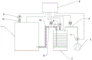
The vacuum drying system according to the embodiment of the present invention includes a vacuum pump 3, a cold trap 2, a vacuum drying apparatus 1, a first pressure gauge 7, a second pressure gauge 8, a third pressure gauge 9, a first solenoid valve 4, a second solenoid valve 5, and a controller 6. The extraction opening of the vacuum pump 3 is connected with the outlet of the cold trap 2 through a first pipeline, and the inlet of the cold trap 2 is connected with the vacuum extraction opening of the vacuum drying equipment 1 through a second pipeline. The first pressure gauge 7 is arranged on the first pipeline, the second pressure gauge 8 is connected with the inner cavity of the cold trap 2, and the third pressure gauge 9 is connected with the inner cavity of the vacuum drying equipment 1. The first solenoid valve 4 is mounted to the first pipeline, and the second solenoid valve 5 is mounted to the second pipeline. The controller 6 is electrically connected to each of the first solenoid valve 4, the second solenoid valve 5, the first pressure gauge 7, the second pressure gauge 8, and the third pressure gauge 9.
According to the vacuum drying system of the embodiment of the invention, the controller 6 can monitor the pressure at the vacuum pump 3, the pressure in the cold trap 2 and the pressure in the vacuum drying equipment 1 in real time through the first pressure gauge 7, the second pressure gauge 8 and the third pressure gauge 9 respectively, and can monitor the temperature in the vacuum drying equipment 1 and the temperature in the cold trap 2 through the temperature sensors in the vacuum drying equipment 1 and the cold trap 2. Meanwhile, the controller 6 can coordinate the parameter relation by controlling the opening and closing of the first electromagnetic valve 4 and the second electromagnetic valve 5 and controlling the temperature rise and fall of the vacuum drying equipment 1 and the cold trap 2, so that the mutual matching of the water evaporation speed in the vacuum box body, the condensation efficiency of the cold trap 2 and the volume of the cold trap 2 is ensured at all times, the situation that the water evaporation amount of the material to be dried with high water content is excessively large in the drying process is effectively avoided, the water vacuum pump 3 is effectively avoided, the service life of the vacuum drying system is prolonged, and the drying efficiency of the vacuum drying system is improved.
The vacuum drying apparatus 1 itself has a heating system and a temperature sensor and is electrically connected to the controller 6, that is, the vacuum drying apparatus 1 can autonomously adjust the internal temperature and transmit temperature information to the controller 6 in real time through the temperature sensor. Meanwhile, the cold trap 2 is also provided with a temperature sensor, a cooling medium and a cooling system are arranged outside the cavity, and the cooling system has an ice melting function, at the moment, the controller 6 controls the cooling system to adjust the temperature of the cooling medium, and the temperature sensor on the cold trap 2 also transmits the temperature information in the cold trap 2 to the controller 6 in real time.
In some embodiments, as shown in fig. 1, the outer periphery of the second conduit is provided with a first heat trace strip 10.
When the material to be dried is dried, the first heat tracing band 10 continuously operates to heat the second pipeline, thereby preventing condensate water from forming in the second pipeline to influence the air pressure difference between the cold trap 2 and the vacuum drying equipment 1, and ensuring the stable and reliable operation of the vacuum drying system.
In some embodiments, as shown in fig. 1, the second pressure gauge 8 is connected to the inner cavity of the cold trap 2 through a third pipeline, the third pressure gauge 9 is connected to the inner cavity of the vacuum drying apparatus 1 through a fourth pipeline, and the peripheries of the third pipeline and the fourth pipeline are respectively provided with a second heat tracing band 11 and a third heat tracing band 12.
At the time of drying the material to be dried, the second heat tracing band 11 and the third heat tracing band 12 also continuously operate to heat the third pipe and the fourth pipe, thereby preventing condensed water from forming in the third pipe and the fourth pipe to affect the pressure detection accuracy of the cold trap 2 and the vacuum drying apparatus 1 by the second pressure gauge 8 and the third pressure gauge 9.
In some embodiments, the vacuum drying apparatus 1 includes any one of a vacuum drying oven, a single cone vacuum drying apparatus 1, a tunnel vacuum drying apparatus 1, a conveyor vacuum drying apparatus 1, a vertical kettle vacuum drying apparatus 1, a horizontal kettle vacuum drying apparatus 1, and a double cone vacuum drying apparatus 1. Namely, the vacuum drying equipment 1 only needs to be provided with a cavity capable of vacuumizing and a heating system capable of heating the cavity, and the vacuum drying system is strong in application.
The use method of the vacuum drying system according to the embodiment of the invention is based on the vacuum drying system according to any one of the embodiments, and comprises the following steps:
the material to be dried is placed in the vacuum drying equipment 1, the vacuum pump 3 is started, and the pressure in the vacuum drying equipment 1 is vacuumized to a set pressure P1 or lower than P1 through the first pressure gauge 7.
Regulating the temperature in the cold trap 2 to a pre-cooling temperature T1 through a controller 6, and determining the maximum fluctuation value T1 of the temperature in the cold trap 2;
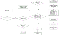
s1: raising the temperature in the vacuum drying equipment 1 from an initial temperature RT to RT+t2, wherein T2 is a temperature regulation step for each time, and the temperature in the cold trap 2 is monitored by taking a set time T as a unit; at this time, if the temperature in the cold trap 2 is kept lower than t1+t1, the temperature in the vacuum drying apparatus 1 is raised to rt+2t2; if the temperature in the cold trap 2 exceeds T1+t1, closing the first electromagnetic valve 4 and the second electromagnetic valve 5, reducing the temperature in the vacuum drying equipment 1 by T2, and opening the first electromagnetic valve 4 and the second electromagnetic valve 5 after recovering the temperature in the cold trap 2 to T1;
step S1 is repeated until the temperature in the vacuum drying apparatus 1 rises to the maximum drying temperature T2.
That is, in the case where the temperature in the cold trap 2 is kept lower than t1+t1 at all times, the vacuum drying apparatus 1 increases the temperature T2 every set time T until the maximum drying temperature T2 is reached. If the temperature in the cold trap 2 is higher than t1+t1 in this process, the temperature in the vacuum drying apparatus 1 is reduced by T2, and the first electromagnetic valve 4 and the second electromagnetic valve 5 are closed to prevent the moisture in the vacuum drying apparatus 1 from entering the cold trap 2, and further prevent the moisture from entering the vacuum pump 3 due to the fact that the moisture cannot be condensed in time in the cold trap 2 until the temperature of the cold trap 2 is reduced to T1, the first control valve and the second control valve are opened, and the step S1 is continuously repeated.
Technical advantages of the method for using the vacuum drying system according to the embodiment of the present invention are the same as those of the vacuum drying system of the above embodiment, and will not be described here again.
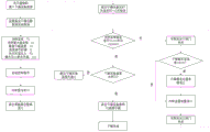
In some embodiments, the pressure P2 in the cold trap 2 and the pressure P3 at the vacuum pump 3 are obtained by the second pressure gauge 8 and the third pressure gauge 9, respectively, and the difference P1 between P1 and P2, the difference P2 between P2 and P3, and the difference Δp between P1 and P2 are determined. Wherein, when the step S1 is carried out,
if p1 is more than p2 and p1-p2 is more than deltap, the first electromagnetic valve 4 and the second electromagnetic valve 5 are closed, the heating of the vacuum drying equipment 1 is stopped, the temperature is naturally reduced, and the first electromagnetic valve 4 and the second electromagnetic valve 5 are opened after the cold trap 2 performs an deicing procedure. When p1 is more than p2 and p1-p2 is more than deltap, the blockage between the vacuum drying equipment 1 and the air inlet of the cold trap 2 (the second pipeline) can be deduced, and the operation realizes the dredging of the first pipeline and ensures the smooth operation of the vacuum drying equipment 1.
If P1 is less than P2, |p1-p2| > Δp, and P3 is less than P1, the first electromagnetic valve 4 and the second electromagnetic valve 5 are closed, the heating of the vacuum drying equipment 1 is stopped, the temperature is naturally reduced, and the first electromagnetic valve 4 and the second electromagnetic valve 5 are opened after the cold trap 2 performs an deicing procedure. When P1 is smaller than P2, |p1-p2| > Deltap and P3 is smaller than P1, blockage between the cold trap 2 and the vacuum pump 3 (first pipeline) can be deduced, and the operation realizes dredging of the first pipeline and ensures smooth operation of the vacuum drying equipment 1.
And moreover, the temperature and pressure linkage adjustment of the vacuum drying equipment 1 and the cold trap 2 is realized through the controller 6, so that the production cost is saved in the vacuum drying process, and the working efficiency of the vacuum drying equipment 1 and the cold trap 2 is improved.
In some embodiments, when step S1 is performed, if P1 < P2, |p1-p2| > Δp, P3> P1, it is determined that the vacuum pump 3 is damaged, the first solenoid valve 4 and the second solenoid valve 5 are closed at this time, and the vacuum pump 3 is overhauled. If the pressure in the vacuum drying equipment 1 is greater than P1, judging that the vacuum drying equipment 1 has a sealing problem, closing the second electromagnetic valve 5, stopping heating the vacuum drying equipment 1, naturally cooling, and overhauling the vacuum drying equipment 1. Therefore, when the vacuum drying system is used for drying materials to be dried, the drying process can be stopped in time when the vacuum pump 3 and the vacuum drying equipment 1 are damaged, so that the condition that moisture enters the vacuum pump 3 is avoided, and the usability of the vacuum drying system is ensured.
In some embodiments, each rise in temperature T2 in the vacuum drying apparatus 1 is 5-15 ℃ while the temperature in the cold trap 2 remains below t1+t1 for a set time T.
At this time, the temperature of each rise in the vacuum drying apparatus 1 is not so low that the time to rise to the highest temperature is too long, thereby ensuring the drying efficiency of the vacuum drying system. And will not be too high to effectively ensure that the temperature in the cold trap 2 is continuously below t1+t1.
Specifically, each rise temperature t2 in the vacuum drying apparatus 1 is preferably 10 ℃.
Further, the maximum drying temperature T2 of the vacuum drying apparatus 1 may be 100 ℃ to 180 ℃, and the maximum fluctuation value T1 of the temperature inside the cold trap 2 may be 5 ℃ to 15 ℃. If T2 is 120 ℃, T1 is 10 ℃.
In some embodiments, the set time T to be maintained when the temperature in the cold trap 2 is lower than t1+t1 is 20min-40min.
When the temperature in the vacuum drying equipment 1 is raised every time, the temperature in the cold trap 2 is raised correspondingly, and after the set time T, the temperature can be basically kept stable, and at the moment, if the temperature in the cold trap 2 is still lower than T1+t1, the working efficiency of the cold trap 2 can be effectively ensured.
500g of the dried material was used as a material to be dried by uniformly mixing with 2000g of water, and drying experiments were performed in this example and comparative example.
As shown in fig. 2 and 3, in the present embodiment, a cold trap 2 with a limiting refrigeration temperature of-50 ℃ is used, the maximum condensation amount of the cold trap 2 is 1kg of water, the pre-cooling temperature T1 of the cold trap 2 is set to-40 ℃ by a controller 6, 2500g of material to be dried is placed into a vacuum drying device 1, after the cold trap 2 reaches the set pre-cooling temperature T1, a vacuum pump 3 is started, and a first electromagnetic valve 4 and a second electromagnetic valve 5 are opened. The maximum value T1 of the temperature fluctuation of the cold trap 2 is set to 10 ℃ through the controller 6, the drying temperature T2 of the vacuum drying equipment 1 is set to 120 ℃ for heat preservation, the temperature adjustment step T2 is set to 10 ℃, the pressure P1 of the vacuum drying equipment 1 for starting heating up is set to 1000Pa, and the maximum allowable value of delta P is set to 500Pa.
Starting a vacuum drying program, pre-cooling the cold trap 2 to-40 ℃, starting a vacuum pump 3, wherein the pressure of the vacuum drying equipment 1, the pressure of the cold trap 2 and the pressure of the vacuum pump 3 are all lower than 1000Pa, at the moment, the temperature of the vacuum drying equipment 1 is raised to 40 ℃ from the normal temperature of 30 ℃, the vacuum drying equipment 1 is maintained at the temperature, the temperature of the cold trap 2 is stabilized within the range of-40+/-10 ℃ for 30min, and after the temperature of the vacuum drying equipment 1 is raised to 50 ℃, the temperature of the cold trap 2 is quickly raised to about-25 ℃ and exceeds the set maximum fluctuation range of the temperature of the cold trap 2.
And closing the first electromagnetic valve 4 and the second electromagnetic valve 5, stopping pumping water vapor in the vacuum drying equipment 1 into the cold trap 2, stopping heat preservation of the vacuum drying equipment 1 at the moment, reducing the set temperature to 40 ℃, recovering the temperature of the cold trap 2 to-40 ℃ after 10min, and opening the first electromagnetic valve 4 and the second electromagnetic valve 5 on a vacuum pipe to continue vacuum drying.
The actual temperature of the vacuum drying equipment 1 is reduced in the range of 40 ℃ to 50 ℃, the temperature of the cold trap 2 is stabilized in the range of minus 40 ℃ plus or minus 10 ℃ for 30min, the temperature of the vacuum drying equipment 1 is increased to 50 ℃, the temperature of the cold trap 2 cannot be stabilized in the range of minus 40 ℃ plus or minus 10 ℃, the first electromagnetic valve 4 and the second electromagnetic valve 5 are closed, the set temperature of the vacuum drying equipment 1 is reduced to 40 ℃, and after the cold trap 2 is restored to minus 40 ℃, the first electromagnetic valve 4 and the second electromagnetic valve 5 are opened for continuous drying.
The process is repeated continuously, the temperature of the vacuum drying equipment 1 is increased to 120 ℃, the temperature of the cold trap 2 can be stably maintained at the temperature of < -40 ℃, at this time, the vacuum drying equipment 1 and the cold trap 2 are maintained in respective states, as the evaporation capacity is reduced after the water content of materials is gradually reduced, the condensation effect of the air inlet of the cold trap 2 is obvious and reaches the maximum condensation capacity of the cold trap 2, the air inlet of the cold trap 2 is blocked, the pressure of the vacuum drying equipment 1 is increased, the pressure of the cold trap 2 is consistent with the pressure of the vacuum pump 3 and is close to vacuum, at this time, delta P is more than 500Pa, the controller 6 closes the first electromagnetic valve 4 and the second electromagnetic valve 5, the vacuum drying equipment 1 stops heating and naturally cooling, the temperature is cooled to-40 ℃ after the ice melting procedure is operated through the cold trap 2 for 30min, the pressure of the vacuum drying equipment 1 is increased to 120 ℃ after the pressure of the vacuum drying equipment 1 is reduced to below P1, and drying is continued.
The comparative example adopts a vacuum drying system in the related art to dry the material to be dried, specifically, a vacuumizing port of the vacuum drying equipment is connected with a cold trap through a pipeline, and an air outlet of the cold trap is connected with a vacuum pump. The vacuum drying apparatus is provided with a pressure gauge. 2500g of the high water content material was placed in a vacuum drying apparatus, and a vacuum pump was started to evacuate. When the pressure of the vacuum drying equipment reaches below 1000Pa, the temperature of the vacuum drying equipment is set to 120 ℃ and the vacuum drying is started.
When the vacuum drying equipment is heated to 50 ℃, the temperature of the cold trap is increased to about 0 ℃. At this time, the condensation capacity of the cold trap is obviously reduced, in order to protect the vacuum pump, the vacuumizing valve of the vacuum drying box is closed, the temperature of the vacuum drying equipment is manually set to 40 ℃, and after the cold trap temperature is restored to-40 ℃, the vacuumizing valve of the vacuum drying equipment is opened, and the drying is continued.
After the cold trap, the pressure gauge and the vacuum drying equipment are stable in numerical value, the vacuum drying temperature is gradually increased to 60 ℃. At this time, because the evaporation capacity of the water in the materials is large, the pumping speed of the vacuum pump is limited, a large amount of water vapor cannot be pumped away in time, the pressure gauge pressure of the vacuum drying equipment is increased, the connecting pipeline is longer because of lower ambient temperature, the water vapor is condensed in the connecting pipeline, the connecting pipeline is blocked, the observation window of the vacuum drying equipment is water mist, and the drying efficiency is reduced.
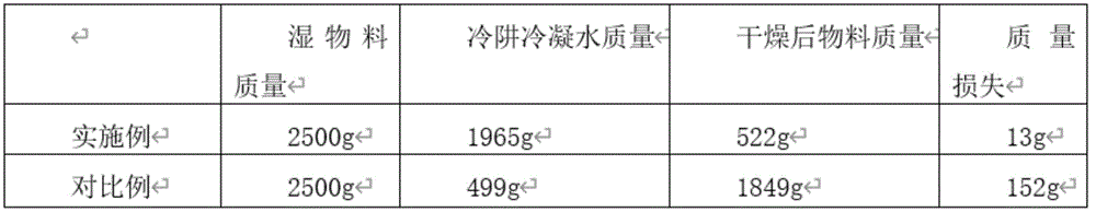
Wherein, the whole running time of the examples and the comparative examples is 12 hours, the materials are taken out the next day for data analysis, and specific values are shown in Table 1. The material loss of the comparative example is much smaller than that of the examples, and the mass loss of the comparative example is much higher than that of the examples, and the mass loss of the comparative example is mainly due to condensation inside the drying cavity after the drying equipment is cooled down, condensation in the connecting pipeline and pumping into the vacuum pump due to the rise of the cold trap temperature. The next day after drying, a large amount of condensed water exists in the connecting pipeline between the vacuum drying equipment and the pressure gauge, and the existence of the condensed water has a great influence on the service life of the pressure gauge and the next operation, and the water removal operation is needed after each drying, otherwise, the numerical accuracy of the pressure gauge is influenced. Therefore, the vacuum drying system of the embodiment can effectively prevent water vapor generated by excessively fast vacuum drying from being fully condensed in a pipeline or entering a vacuum pump, so that vacuum drying equipment is protected, and the service life of the equipment is prolonged.
TABLE 1
In the description of the present invention, it should be understood that the terms "center", "longitudinal", "lateral", "length", "width", "thickness", "upper", "lower", "front", "rear", "left", "right", "vertical", "horizontal", "top", "bottom", "inner", "outer", "clockwise", "counterclockwise", "axial", "radial", "circumferential", etc. indicate orientations or positional relationships based on the orientations or positional relationships shown in the drawings are merely for convenience in describing the present invention and simplifying the description, and do not indicate or imply that the device or element being referred to must have a specific orientation, be configured and operated in a specific orientation, and therefore should not be construed as limiting the present invention.
Furthermore, the terms "first," "second," and the like, are used for descriptive purposes only and are not to be construed as indicating or implying a relative importance or implicitly indicating the number of technical features indicated. Thus, a feature defining "a first" or "a second" may explicitly or implicitly include at least one such feature. In the description of the present invention, the meaning of "plurality" means at least two, for example, two, three, etc., unless specifically defined otherwise.
In the present invention, unless explicitly specified and limited otherwise, the terms "mounted," "connected," "secured," and the like are to be construed broadly, and may be, for example, fixedly connected, detachably connected, or integrally formed; may be mechanically connected, may be electrically connected or may be in communication with each other; either directly or indirectly, through intermediaries, or both, may be in communication with each other or in interaction with each other, unless expressly defined otherwise. The specific meaning of the above terms in the present invention can be understood by those of ordinary skill in the art according to the specific circumstances.
In the present invention, unless expressly stated or limited otherwise, a first feature "up" or "down" a second feature may be the first and second features in direct contact, or the first and second features in indirect contact via an intervening medium. Moreover, a first feature being "above," "over" and "on" a second feature may be a first feature being directly above or obliquely above the second feature, or simply indicating that the first feature is level higher than the second feature. The first feature being "under", "below" and "beneath" the second feature may be the first feature being directly under or obliquely below the second feature, or simply indicating that the first feature is less level than the second feature.
For purposes of this disclosure, the terms "one embodiment," "some embodiments," "example," "a particular example," or "some examples," etc., mean that a particular feature, structure, material, or characteristic described in connection with the embodiment or example is included in at least one embodiment or example of the invention. In this specification, schematic representations of the above terms are not necessarily directed to the same embodiment or example. Furthermore, the particular features, structures, materials, or characteristics described may be combined in any suitable manner in any one or more embodiments or examples. Furthermore, the different embodiments or examples described in this specification and the features of the different embodiments or examples may be combined and combined by those skilled in the art without contradiction.
While the above embodiments have been shown and described, it should be understood that the above embodiments are illustrative and not to be construed as limiting the invention, and that variations, modifications, alternatives, and variations of the above embodiments may be made by those of ordinary skill in the art without departing from the scope of the invention.