Welding method for thin bottom plate of blade type power battery tray
Technical Field
The invention relates to the technical field of new energy automobile processing and manufacturing, in particular to a method for welding a thin bottom plate of a blade type power battery tray.
Background
In recent years, new energy electric vehicles gradually replace fuel automobiles and become increasingly popular automobile types. The power battery in the electric automobile is a storage component of electric energy thereof, and belongs to a core component in the whole automobile. The power battery module is carried by the battery pack shell, and the battery pack shell is connected with the vehicle underframe to form a firm carrying vehicle body. Because the weight of the new energy electric vehicle is closely related to the driving range of the new energy electric vehicle, based on the consideration of light weight of the vehicle body, the aluminum vehicle body structure has excellent comprehensive indexes such as light weight, corrosion resistance and recovery residual value, and becomes the choice of more and more new energy vehicles, the battery pack shell and the battery tray thereof are used as important structural components, account for 20 to 30 percent of the weight of a battery system, are also core energy sources of the new energy vehicles, and play a key role in the safety and protection of a battery module. The lithium battery protection device is generally arranged at the lower part of a vehicle body and is mainly used for protecting the lithium battery from being damaged when the lithium battery is collided and extruded by the outside.
Because still need the connection of pencil between the traditional battery package module, consequently frame tray bottom plate design is the section bar, and the centre has horizontal or fore-and-aft additional strengthening in addition, and overall structure rigidity is better, and non-deformable produces the easy control of manufacturing. The crossbar structure occupies valuable space inside the battery pack. In recent years, blade formula lithium iron phosphate power battery has appeared, and the blade battery need not the module, can directly constitute the battery package by electric core to have more outstanding self structural strength, the horizontal longeron in the battery package has been saved to this kind of battery form, has promoted whole space utilization. The space utilization of the conventional battery is about 40%, and the space utilization of the battery pack of the blade battery can be improved to 60%. The battery that blade battery matches wraps the casing (battery tray) for taking Liang Lv sheet metal casing, compare with traditional battery module frame-type tray, blade battery tray bottom plate adopts 1.5 mm's sheet metal, the centre sets up the additional strengthening of single crossbeam, the degree of difficulty of battery tray manufacturing has been increaseed, higher requirement has been put forward to manufacturing, especially in carrying out overlap joint stirring welding process to battery tray bottom sheet metal and frame aluminum thick plate, because the splice produces a large amount of heats and welding stress, the splice takes place serious distortion, greatly influenced battery tray's technical precision, increase the rejection rate, influence follow-up other part installations.
And (3) searching keywords: welding, friction stir welding, electromagnet, pressing plate, heating and battery tray
1. The new energy automobile battery tray friction stir welding fixture comprises a fixture for friction stir welding; CN202021077233.9; the utility model provides a new energy automobile battery tray anchor clamps for friction stir welding, including the support frame, the clamping station, X axle side pushes away mechanism group, Y axle side pushes away mechanism group, X axle positioning mechanism group, Y axle positioning mechanism group, front end compacting mechanism group, rear end compacting mechanism group, left end compacting mechanism group, right-hand member compacting mechanism group, and two jacking mechanism groups, the clamping station is located on the support frame, the relative both sides of clamping station X axle direction are provided with X axle side and push away mechanism group and X axle positioning mechanism group respectively, the relative both sides of clamping station Y axle direction are provided with Y axle side respectively and push away mechanism group and Y axle positioning mechanism group, front end compacting mechanism group, rear end compacting mechanism group, left end compacting mechanism group, right-hand member compacting mechanism group enclose respectively in the front and back left and right sides of clamping station, two jacking mechanism groups set up the relative both sides below the clamping station respectively. The utility model discloses but the battery tray of the multiple different models of clamping has reduced manufacturing cost, and clamping stability is high.
2. A friction stir welding device suitable for a space surface; CN201910614800.5; the utility model provides a friction stir welding device suitable for space face, which comprises a supporting plate, the first work piece and the second of treating to weld the work piece, open the hair-dryer through control panel, and then treat to weld the upper surface of work piece and the second and treat to weld the work piece to first, open the electro-magnet through control panel, second cylinder and friction stir welding device body, make the electro-magnet treat to weld the work piece to first work piece and the second and treat to weld the work piece and adsorb fixedly, the stir head treats to weld the work piece and the second and treats to weld the work piece to first, be equipped with first cylinder, the first telescopic link of first cylinder promotes the slider and removes, and then make the backup pad remove, when the slider removes the one end of spout, control panel control electro-magnet closes, and control the first telescopic link shrink of first cylinder, make the slider remove to the initial condition, so reciprocal, realize treating to weld the friction stir welding of work piece and second promptly, facilitate the use.
3. A friction stir welding electromagnet tool; CN202121083570.3; the utility model provides a friction stir welding electro-magnet frock, includes that base, locating piece, frame fixture, bottom plate press and cover mechanism and lock attach the mechanism, and is a plurality of the locating piece sets up on the base corresponding to the periphery profile wall distribution of frame, a plurality of groups frame fixture sets up on the base corresponding to the outline of frame, just the frame passes through frame fixture centre gripping is in the base top, the inner circle region that the base is located a plurality of locating pieces is provided with the lock and attaches the mechanism, the top interval of lock attach the mechanism is provided with the bottom plate and presses and cover the mechanism, and the centre gripping is inhaled by the magnetism to the bottom plate is in between lock attach the mechanism and the bottom plate press and cover the mechanism, its overall structure is simple, convenient to use.
4. The new energy automobile battery box friction stir welding clamp; CN202120893459.4; a welding fixture, in particular to a new energy automobile battery box friction stir welding fixture. The gantry crane is characterized by comprising a gantry frame and a rectangular bottom plate, wherein the rectangular bottom plate is positioned between two vertical parts of the gantry frame. Supporting blocks are arranged on the periphery of the upper surface of the rectangular bottom plate. And the rectangular bottom plates positioned on the outer sides of the supporting blocks on the long sides of the rectangular bottom plates are all provided with lever cylinders which are vertically arranged. The rectangular bottom plate positioned at the outer side of the supporting block on one short side of the rectangular bottom plate is provided with a first rotating cylinder. And the rectangular bottom plate positioned at the outer side of the supporting block on the other short edge of the upper surface of the rectangular bottom plate is provided with a supporting cylinder. The outer side of the supporting cylinder is provided with a second rotating cylinder. An electromagnet is fixed on the upper surface of the rectangular bottom plate between the supporting blocks. A driving cylinder is arranged on the transverse part of the portal frame, a supporting plate is fixed on the lower end of a piston rod of the driving cylinder, and a water cooling plate is connected below the supporting plate. The fixture has the advantages of higher working efficiency, higher repeated positioning precision and good integral cooling effect.
5. A friction stir welding tool with a heating function; application No.: CN201711216631.7; and (3) abstract: a friction stir welding tool with a heating function comprises a base, wherein a workpiece placing area for installing a workpiece to be welded is arranged on the base, lateral pressing mechanisms are respectively arranged on the left side and the right side of the workpiece placing area on the base, and end pressing mechanisms are respectively arranged on the front side and the rear side of the workpiece placing area on the base; the base is also provided with a plurality of longitudinal pressing mechanisms for pressing workpieces, and the base is provided with an electric heating element for heating the back of the workpiece to be welded. The invention is convenient for installing and fixing the left and right workpieces to be welded on the clamp, reduces the temperature difference of the workpieces in the thickness direction and improves the welding quality of the thick plate friction stir welding in order to enlarge a welding process window, a plurality of electric heating elements are pre-embedded on the base, and when the thick plate is welded, the electric heating elements are electrified, so that the workpieces are heated additionally in the welding process, the temperature difference of the welding seam in the thickness direction is reduced, and the welding quality is improved.
Although publications appear in the prior art as well: a friction stir welding electromagnet tool; CN202121083570.3; the stirring welding mode that an electromagnet adsorbs a pressing plate and a tray workpiece is pressed is adopted, but the pressing plate device cannot be automatically lifted and moved; secondly, the flatness of the thin bottom plate after stirring welding in the mode is still insufficient, and the product requirement cannot be met.
Disclosure of Invention
The invention aims to provide a method for welding a thin bottom plate of a blade type power battery tray, which is specially applied to friction stir welding of the bottom plate of the blade type power battery tray and can eliminate the deformation problem of the bottom plate in the welding process of the thin bottom plate.
In order to achieve the purpose, the technical scheme of the invention is as follows:
a method for welding a thin bottom plate of a blade type power battery tray comprises the steps of heating a frame and the thin bottom plate of the battery tray to a preset temperature by a heating pipe before friction stir welding, then performing friction stir welding, and pressing the thin bottom plate of the battery tray by a pressing plate while performing friction stir welding.
A method for welding a thin bottom plate of a blade type power battery tray further comprises the following steps:
A. powering on equipment, placing the battery tray with the thin bottom plate and the frame fixed by spot welding on a heating tool, accurately positioning the battery tray by using a side top cylinder, and then clamping and fixing the battery tray by using a pneumatic clamp;
B. the movable frame drives the pressing plate to move right above the heating tool, the lifting cylinder descends to place the pressing plate right above the battery tray, the bolt retracts, the movable frame is separated from the pressing plate, and the movable frame moves back to the original position;
C. turning on an electromagnet switch, pressing a thin bottom plate of the battery tray by a pressing plate, turning on an electric heating tube heating switch, heating the battery tray by a heating tool, and performing friction stir welding operation of the bottom plate and the frame when the frame and the thin bottom plate of the battery are heated to a preset temperature;
D. after the friction stir welding is finished, the electromagnet is turned off and the heating is carried out, the sliding frame is moved into the position, the hanging plate descends to the position, the bolt extends out to penetrate through the lifting lug, the hanging plate is lifted, and then the sliding frame is moved back to the original position;
E. and (5) completing the friction stir welding operation of the battery tray, loosening the pneumatic clamp and taking out the tray.
The heating pipes comprise bottom plate heating pipes and frame heating pipes, and the bottom plate heating pipes are arranged in the adjacent middle of each row of electromagnets and are matched with the thin bottom plate; the frame heating pipe is arranged around the electromagnet array and matched with the frame.
The heating temperature of the thin bottom plate and the frame is differential heating, and the heating temperature of the thin bottom plate is higher than that of the frame.
The heating temperature of the thin bottom plate is 70 ℃, and the heating temperature of the frame is 40 ℃.
The device is characterized in that a guide rail is arranged on a rack of the device, a sliding frame capable of sliding left and right is arranged on the guide rail, a lifting cylinder is fixedly arranged at the top of the sliding frame, the end part of a piston rod downwards of the lifting cylinder is connected with a hanging plate, and a pressing plate can be movably connected below the hanging plate; one end of the rack is fixedly provided with a heating tool, the upper end surface of the heating tool is a welding table top, and an electromagnet array and a heating pipe are arranged below the welding table top.
A plurality of vertical guide rods are arranged on the hanging plate, and corresponding guide rings are arranged at corresponding positions of the sliding frame.
The clamp plate up end sets up horizontally bolt cylinder, and the piston rod installation bolt of bolt cylinder, hanger plate up end correspond the position and set up the lug. The guide rod can guide the hanging plate to move along the vertical direction, and deflection phenomena are avoided.
A plurality of clamps are arranged around the heating tool, and the opening and closing of the clamps are controlled by the electric control of a hand rotating handle of a welding cylinder arranged on the rack. The clamp is used for clamping and positioning the battery tray.
And a plurality of side jacking cylinders are arranged at two ends of the heating tool. And the side top cylinder is used for pushing the limiting position to center the battery tray.
The heating pipes comprise bottom plate heating pipes and frame heating pipes, the bottom plate heating pipes are arranged in the middle of the adjacent rows of electromagnets, and the frame heating pipes are arranged around the electromagnet arrays. Because the thickness of the frame and the middle part of the battery tray is not uniform, the heat quantity required to be heated is different. Therefore, the heating of the battery tray is more uniform and controllable due to the combined action of the bottom plate heating pipe and the frame heating pipe.
The invention has the advantages that:
1. the invention is specially applied to the friction stir welding of the thin bottom plate of the blade battery, and the heating tool plays the following two roles: the method comprises the following steps: because the thin bottom plate has thinner wall thickness and the frame is a thick plate or a section with the thickness of 5-6mm, the temperature difference between the high-temperature stirring part and the surrounding cooling part is smaller in the process of high-temperature stirring welding of the lap joint surface of the thin bottom plate and the frame, the material fluidity is better in the stirring process, and the welding seam is more compact and firm; secondly, under the action of the suction pressure of the electromagnet, the thin bottom plate is continuously pressed and heated, the welding internal stress borne by the thin bottom plate in the welding process is continuously released and resolved, the stress cannot be remained, finally, the flatness of the blade power battery tray can meet the product requirement, and the blade power battery tray cannot deform again due to the release of the residual stress in the later-stage use process.
2. In the invention, the frame and the thin bottom plate are preferably heated and welded by adopting a differential heating mode, the obtained thin bottom plate has better flatness, and the technical effect of achieving the best flatness under the condition of lowest heating energy consumption is realized.
3. The tool equipment has the advantages of high automation degree, convenience in operation, zone control of heating control, accurate and reliable temperature control, capability of enabling operators to be on duty only through simple training and convenience in maintenance.
Description of the drawings:
FIG. 1 is a schematic top view of the present invention;
FIG. 2 is an enlarged view of section I of FIG. 1;
FIG. 3 is an enlarged structural view taken at II in FIG. 1;
FIG. 4 is a schematic front view of the present invention;
FIG. 5 is a schematic view of a welded state structure of a battery tray;
fig. 6 is a schematic structural view of the appearance of the blade type power battery tray;
FIG. 7 is a graph of flatness of the welded blank at different temperatures in the case of uniform temperature heating;
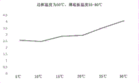
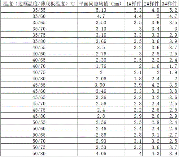
FIG. 8 is a graph of flatness of a welded base plate at a frame temperature of 35 ℃ and a thin base plate temperature of 55-80 ℃ in a differential heating state;
FIG. 9 is a graph of flatness of a welded base plate at a frame temperature of 40 ℃ and a thin base plate temperature of 55-80 ℃ in a differential heating state;
FIG. 10 is a coordinate diagram of the flatness of a welded base plate at a frame temperature of 45 ℃ and a thin base plate temperature of 55-80 ℃ in a differential heating state;
FIG. 11 is a graph of flatness of a welded base plate at a frame temperature of 50 ℃ and a thin base plate temperature of 55-80 ℃ in a differential heating state;
the serial numbers and component names in the figures are: 1-a frame; 2-a track; 3-sliding rack; 31-a lifting cylinder; 32-a hanger plate; 33-a guide rod; 34-a latch cylinder; 4, pressing a plate; 41-lifting lugs; 5, heating a tool; 51-welding a table top; 52-a clamp; 53-side top cylinder; 54-an electromagnet switch; 55-an electromagnet; 56-welding the cylinder handle; 57-base plate heating tube; 58-frame heating tube; 61-front and back rims; 62-left and right rims; 63-thin bottom plate.
Detailed Description
Example 1
A method for welding a thin bottom plate of a blade type power battery tray comprises the steps of heating a frame and the thin bottom plate of the battery tray to a preset temperature by a heating pipe before friction stir welding, and pressing the thin bottom plate of the battery tray by a pressing plate while performing friction stir welding.
The welding method of the thin bottom plate of the blade type power battery tray further comprises the following steps:
A. powering on equipment, placing the battery tray with the thin bottom plate and the frame fixed by spot welding on a heating tool, accurately positioning the battery tray by using a side top cylinder, and then clamping and fixing the battery tray by using a pneumatic clamp;
B. the movable frame drives the pressing plate to move right above the heating tool, the lifting cylinder descends to place the pressing plate right above the battery tray, the bolt retracts, the movable frame is separated from the pressing plate, and the movable frame moves back to the original position;
C. turning on an electromagnet switch, pressing a thin bottom plate of the battery tray by a pressing plate, turning on an electric heating tube heating switch, heating the battery tray by a heating tool, and performing friction stir welding operation of the bottom plate and the frame when the frame and the thin bottom plate of the battery are heated to a preset temperature;
D. after the friction stir welding is finished, the electromagnet is turned off and the heating is carried out, the sliding frame is moved into the position, the hanging plate descends to the proper position, the bolt extends out of the lifting lug, the hanging plate is lifted, and then the sliding frame is moved back to the proper position;
E. and (5) completing the friction stir welding operation of the battery tray, loosening the pneumatic clamp and taking out the tray.
The heating pipes comprise a bottom plate heating pipe 57 and a frame heating pipe 58, wherein the bottom plate heating pipe 57 is arranged in the adjacent middle of each row of electromagnets 55 and is matched with the thin bottom plate; the frame heating pipes 58 are arranged around the array of electromagnets 55 to match the position of the frame.
The heating temperature of the thin bottom plate and the frame is 55 ℃ at the same temperature.
The heating temperature of the thin bottom plate and the frame is differential heating, and the heating temperature of the thin bottom plate is higher than that of the frame.
The heating temperature of the thin bottom plate is 70 ℃, and the heating temperature of the frame is 40 ℃.
The application example is as follows:
a blade type power battery tray is formed by welding a 6061 alloy aluminum alloy frame and a cold-rolled 5083 aluminum plate with the thickness of 1.5mm in a stirring manner, the size of the aluminum alloy tray is 1210X 1777.6mm, and after the tray is welded with a back bottom plate, the flatness of the aluminum alloy tray is less than 4mm. Meets the index requirement that the degree of deformation of the product is less than or equal to 4mm.
Same power blade battery tray adopts traditional mode to carry out the crossbeam welding, directly carries out friction stir welding with the frame with the bottom plate, and welding aluminum alloy tray ground flatness (unevenness) size is for being greater than 4mm.
Under the conditions, the applicant welds the bottom plate under the condition of uniform temperature heating at 35-80 ℃ for flatness test, places the welded battery tray on a detection platform, and measures the maximum distance between the bottom plate and the platform surface.
The mean flatness of the welded floor at each temperature state is expressed in coordinates as shown in fig. 7:
from the above, when the frame and the thin bottom plate are heated to 55 ℃ at the same temperature, the welding plane gap of the thin bottom plate is the smallest, which is due to the following reasons: when the heating temperature is lower than 55 ℃, the residual stress caused by welding in the thin bottom plate is not fully released, and when the pressure of the pressing plate is lost, the thin bottom plate is bent due to the residual stress caused by welding; when the heating temperature is 55 ℃, heat generated in a welding area by friction stir welding is superposed with heat brought by a heating pipe, so that the temperature around the welding area is too high and even approaches to the overburning temperature of the aluminum alloy, and the thin bottom plate generates orange peel coarse crystals and slightly deforms near the welding area, namely the lap joint of the frame and the thin bottom plate.
Therefore, if the thin bottom plate and the frame are heated to about 55 ℃ at the same time, the phenomenon can be avoided, and the thin bottom plate and the frame are in a more golden balance point.
Then, the battery frame is heated in a differential temperature heating mode to be stirred and welded, and the test results are as follows:
dividing the data into four groups, and making four curve graphs for analysis according to the difference between the frame temperature and the thin baseplate temperature: the ordinate of the graph is the plane gap value, and the abscissa is the temperature difference between the frame temperature and the thin bottom plate, and as can be seen from fig. 8-11, the relationship between the temperature difference and the plane gap value is approximately a concave curve, which indicates that there is an optimum point for the temperature difference between the frame temperature and the thin bottom plate, and it is preferable that the temperature difference is approximately 30-35 ℃.
From the above, in the actual production process, when the frame and the thin bottom plate of the battery tray are heated at 40/70 ℃, the plane gap is the smallest, which is caused by: when the temperature of the thin bottom plate is higher, but the temperature of the frame is lower, and in the stirring welding process, the heat of the thin bottom plate can be continuously conducted to the frame at the lap joint of the thin bottom plate and the frame, even if the heat generated by the stirring welding is larger, the heat does not exceed the overburning temperature of the aluminum alloy, the thin bottom plate can be kept in a shape under continuous pressurization of the pressing plate in the whole stirring welding process, and the welding edge still keeps flat. From this, the gold balance point of the welding process is found.