CN115750466A - Air blower - Google Patents
Air blower Download PDFInfo
- Publication number
- CN115750466A CN115750466A CN202211054597.9A CN202211054597A CN115750466A CN 115750466 A CN115750466 A CN 115750466A CN 202211054597 A CN202211054597 A CN 202211054597A CN 115750466 A CN115750466 A CN 115750466A
- Authority
- CN
- China
- Prior art keywords
- guide
- tower
- plate
- air
- guide plate
- Prior art date
- Legal status (The legal status is an assumption and is not a legal conclusion. Google has not performed a legal analysis and makes no representation as to the accuracy of the status listed.)
- Pending
Links
Images


Classifications
-
- F—MECHANICAL ENGINEERING; LIGHTING; HEATING; WEAPONS; BLASTING
- F04—POSITIVE - DISPLACEMENT MACHINES FOR LIQUIDS; PUMPS FOR LIQUIDS OR ELASTIC FLUIDS
- F04D—NON-POSITIVE-DISPLACEMENT PUMPS
- F04D25/00—Pumping installations or systems
- F04D25/02—Units comprising pumps and their driving means
- F04D25/08—Units comprising pumps and their driving means the working fluid being air, e.g. for ventilation
-
- F—MECHANICAL ENGINEERING; LIGHTING; HEATING; WEAPONS; BLASTING
- F04—POSITIVE - DISPLACEMENT MACHINES FOR LIQUIDS; PUMPS FOR LIQUIDS OR ELASTIC FLUIDS
- F04D—NON-POSITIVE-DISPLACEMENT PUMPS
- F04D25/00—Pumping installations or systems
- F04D25/02—Units comprising pumps and their driving means
- F04D25/06—Units comprising pumps and their driving means the pump being electrically driven
-
- F—MECHANICAL ENGINEERING; LIGHTING; HEATING; WEAPONS; BLASTING
- F04—POSITIVE - DISPLACEMENT MACHINES FOR LIQUIDS; PUMPS FOR LIQUIDS OR ELASTIC FLUIDS
- F04D—NON-POSITIVE-DISPLACEMENT PUMPS
- F04D25/00—Pumping installations or systems
- F04D25/02—Units comprising pumps and their driving means
- F04D25/08—Units comprising pumps and their driving means the working fluid being air, e.g. for ventilation
- F04D25/10—Units comprising pumps and their driving means the working fluid being air, e.g. for ventilation the unit having provisions for automatically changing direction of output air
-
- F—MECHANICAL ENGINEERING; LIGHTING; HEATING; WEAPONS; BLASTING
- F04—POSITIVE - DISPLACEMENT MACHINES FOR LIQUIDS; PUMPS FOR LIQUIDS OR ELASTIC FLUIDS
- F04D—NON-POSITIVE-DISPLACEMENT PUMPS
- F04D29/00—Details, component parts, or accessories
- F04D29/26—Rotors specially for elastic fluids
- F04D29/263—Rotors specially for elastic fluids mounting fan or blower rotors on shafts
-
- F—MECHANICAL ENGINEERING; LIGHTING; HEATING; WEAPONS; BLASTING
- F04—POSITIVE - DISPLACEMENT MACHINES FOR LIQUIDS; PUMPS FOR LIQUIDS OR ELASTIC FLUIDS
- F04D—NON-POSITIVE-DISPLACEMENT PUMPS
- F04D29/00—Details, component parts, or accessories
- F04D29/40—Casings; Connections of working fluid
- F04D29/403—Casings; Connections of working fluid especially adapted for elastic fluid pumps
-
- F—MECHANICAL ENGINEERING; LIGHTING; HEATING; WEAPONS; BLASTING
- F04—POSITIVE - DISPLACEMENT MACHINES FOR LIQUIDS; PUMPS FOR LIQUIDS OR ELASTIC FLUIDS
- F04D—NON-POSITIVE-DISPLACEMENT PUMPS
- F04D29/00—Details, component parts, or accessories
- F04D29/40—Casings; Connections of working fluid
- F04D29/42—Casings; Connections of working fluid for radial or helico-centrifugal pumps
- F04D29/44—Fluid-guiding means, e.g. diffusers
- F04D29/46—Fluid-guiding means, e.g. diffusers adjustable
- F04D29/462—Fluid-guiding means, e.g. diffusers adjustable especially adapted for elastic fluid pumps
-
- F—MECHANICAL ENGINEERING; LIGHTING; HEATING; WEAPONS; BLASTING
- F04—POSITIVE - DISPLACEMENT MACHINES FOR LIQUIDS; PUMPS FOR LIQUIDS OR ELASTIC FLUIDS
- F04D—NON-POSITIVE-DISPLACEMENT PUMPS
- F04D29/00—Details, component parts, or accessories
- F04D29/40—Casings; Connections of working fluid
- F04D29/52—Casings; Connections of working fluid for axial pumps
- F04D29/54—Fluid-guiding means, e.g. diffusers
- F04D29/56—Fluid-guiding means, e.g. diffusers adjustable
- F04D29/563—Fluid-guiding means, e.g. diffusers adjustable specially adapted for elastic fluid pumps
-
- F—MECHANICAL ENGINEERING; LIGHTING; HEATING; WEAPONS; BLASTING
- F04—POSITIVE - DISPLACEMENT MACHINES FOR LIQUIDS; PUMPS FOR LIQUIDS OR ELASTIC FLUIDS
- F04F—PUMPING OF FLUID BY DIRECT CONTACT OF ANOTHER FLUID OR BY USING INERTIA OF FLUID TO BE PUMPED; SIPHONS
- F04F5/00—Jet pumps, i.e. devices in which flow is induced by pressure drop caused by velocity of another fluid flow
- F04F5/14—Jet pumps, i.e. devices in which flow is induced by pressure drop caused by velocity of another fluid flow the inducing fluid being elastic fluid
- F04F5/16—Jet pumps, i.e. devices in which flow is induced by pressure drop caused by velocity of another fluid flow the inducing fluid being elastic fluid displacing elastic fluids
-
- F—MECHANICAL ENGINEERING; LIGHTING; HEATING; WEAPONS; BLASTING
- F04—POSITIVE - DISPLACEMENT MACHINES FOR LIQUIDS; PUMPS FOR LIQUIDS OR ELASTIC FLUIDS
- F04F—PUMPING OF FLUID BY DIRECT CONTACT OF ANOTHER FLUID OR BY USING INERTIA OF FLUID TO BE PUMPED; SIPHONS
- F04F5/00—Jet pumps, i.e. devices in which flow is induced by pressure drop caused by velocity of another fluid flow
- F04F5/44—Component parts, details, or accessories not provided for in, or of interest apart from, groups F04F5/02 - F04F5/42
- F04F5/46—Arrangements of nozzles
- F04F5/466—Arrangements of nozzles with a plurality of nozzles arranged in parallel
-
- F—MECHANICAL ENGINEERING; LIGHTING; HEATING; WEAPONS; BLASTING
- F16—ENGINEERING ELEMENTS AND UNITS; GENERAL MEASURES FOR PRODUCING AND MAINTAINING EFFECTIVE FUNCTIONING OF MACHINES OR INSTALLATIONS; THERMAL INSULATION IN GENERAL
- F16H—GEARING
- F16H19/00—Gearings comprising essentially only toothed gears or friction members and not capable of conveying indefinitely-continuing rotary motion
- F16H19/02—Gearings comprising essentially only toothed gears or friction members and not capable of conveying indefinitely-continuing rotary motion for interconverting rotary or oscillating motion and reciprocating motion
- F16H19/04—Gearings comprising essentially only toothed gears or friction members and not capable of conveying indefinitely-continuing rotary motion for interconverting rotary or oscillating motion and reciprocating motion comprising a rack
-
- F—MECHANICAL ENGINEERING; LIGHTING; HEATING; WEAPONS; BLASTING
- F24—HEATING; RANGES; VENTILATING
- F24F—AIR-CONDITIONING; AIR-HUMIDIFICATION; VENTILATION; USE OF AIR CURRENTS FOR SCREENING
- F24F13/00—Details common to, or for air-conditioning, air-humidification, ventilation or use of air currents for screening
- F24F13/08—Air-flow control members, e.g. louvres, grilles, flaps or guide plates
- F24F13/10—Air-flow control members, e.g. louvres, grilles, flaps or guide plates movable, e.g. dampers
- F24F13/12—Air-flow control members, e.g. louvres, grilles, flaps or guide plates movable, e.g. dampers built up of sliding members
-
- F—MECHANICAL ENGINEERING; LIGHTING; HEATING; WEAPONS; BLASTING
- F24—HEATING; RANGES; VENTILATING
- F24F—AIR-CONDITIONING; AIR-HUMIDIFICATION; VENTILATION; USE OF AIR CURRENTS FOR SCREENING
- F24F8/00—Treatment, e.g. purification, of air supplied to human living or working spaces otherwise than by heating, cooling, humidifying or drying
- F24F8/10—Treatment, e.g. purification, of air supplied to human living or working spaces otherwise than by heating, cooling, humidifying or drying by separation, e.g. by filtering
-
- F—MECHANICAL ENGINEERING; LIGHTING; HEATING; WEAPONS; BLASTING
- F05—INDEXING SCHEMES RELATING TO ENGINES OR PUMPS IN VARIOUS SUBCLASSES OF CLASSES F01-F04
- F05D—INDEXING SCHEME FOR ASPECTS RELATING TO NON-POSITIVE-DISPLACEMENT MACHINES OR ENGINES, GAS-TURBINES OR JET-PROPULSION PLANTS
- F05D2250/00—Geometry
- F05D2250/50—Inlet or outlet
- F05D2250/52—Outlet
-
- F—MECHANICAL ENGINEERING; LIGHTING; HEATING; WEAPONS; BLASTING
- F05—INDEXING SCHEMES RELATING TO ENGINES OR PUMPS IN VARIOUS SUBCLASSES OF CLASSES F01-F04
- F05D—INDEXING SCHEME FOR ASPECTS RELATING TO NON-POSITIVE-DISPLACEMENT MACHINES OR ENGINES, GAS-TURBINES OR JET-PROPULSION PLANTS
- F05D2260/00—Function
- F05D2260/40—Transmission of power
- F05D2260/403—Transmission of power through the shape of the drive components
- F05D2260/4031—Transmission of power through the shape of the drive components as in toothed gearing
-
- F—MECHANICAL ENGINEERING; LIGHTING; HEATING; WEAPONS; BLASTING
- F05—INDEXING SCHEMES RELATING TO ENGINES OR PUMPS IN VARIOUS SUBCLASSES OF CLASSES F01-F04
- F05D—INDEXING SCHEME FOR ASPECTS RELATING TO NON-POSITIVE-DISPLACEMENT MACHINES OR ENGINES, GAS-TURBINES OR JET-PROPULSION PLANTS
- F05D2260/00—Function
- F05D2260/50—Kinematic linkage, i.e. transmission of position
- F05D2260/53—Kinematic linkage, i.e. transmission of position using gears
-
- F—MECHANICAL ENGINEERING; LIGHTING; HEATING; WEAPONS; BLASTING
- F05—INDEXING SCHEMES RELATING TO ENGINES OR PUMPS IN VARIOUS SUBCLASSES OF CLASSES F01-F04
- F05D—INDEXING SCHEME FOR ASPECTS RELATING TO NON-POSITIVE-DISPLACEMENT MACHINES OR ENGINES, GAS-TURBINES OR JET-PROPULSION PLANTS
- F05D2270/00—Control
- F05D2270/01—Purpose of the control system
- F05D2270/17—Purpose of the control system to control boundary layer
- F05D2270/173—Purpose of the control system to control boundary layer by the Coanda effect
-
- F—MECHANICAL ENGINEERING; LIGHTING; HEATING; WEAPONS; BLASTING
- F24—HEATING; RANGES; VENTILATING
- F24F—AIR-CONDITIONING; AIR-HUMIDIFICATION; VENTILATION; USE OF AIR CURRENTS FOR SCREENING
- F24F1/00—Room units for air-conditioning, e.g. separate or self-contained units or units receiving primary air from a central station
- F24F1/0007—Indoor units, e.g. fan coil units
- F24F1/0011—Indoor units, e.g. fan coil units characterised by air outlets
- F24F1/0014—Indoor units, e.g. fan coil units characterised by air outlets having two or more outlet openings
-
- F—MECHANICAL ENGINEERING; LIGHTING; HEATING; WEAPONS; BLASTING
- F24—HEATING; RANGES; VENTILATING
- F24F—AIR-CONDITIONING; AIR-HUMIDIFICATION; VENTILATION; USE OF AIR CURRENTS FOR SCREENING
- F24F13/00—Details common to, or for air-conditioning, air-humidification, ventilation or use of air currents for screening
- F24F13/20—Casings or covers
- F24F2013/205—Mounting a ventilator fan therein
-
- F—MECHANICAL ENGINEERING; LIGHTING; HEATING; WEAPONS; BLASTING
- F24—HEATING; RANGES; VENTILATING
- F24F—AIR-CONDITIONING; AIR-HUMIDIFICATION; VENTILATION; USE OF AIR CURRENTS FOR SCREENING
- F24F2221/00—Details or features not otherwise provided for
- F24F2221/28—Details or features not otherwise provided for using the Coanda effect
Landscapes
- Engineering & Computer Science (AREA)
- General Engineering & Computer Science (AREA)
- Mechanical Engineering (AREA)
- Chemical & Material Sciences (AREA)
- Combustion & Propulsion (AREA)
- Physics & Mathematics (AREA)
- Fluid Mechanics (AREA)
- Structures Of Non-Positive Displacement Pumps (AREA)
Abstract
本发明的送风机包括:下壳体,形成有吸入口;第一塔,从下壳体向上侧延伸,形成有第一吐出口;第二塔,从下壳体向上侧延伸,形成有第二吐出口;风扇,可旋转地配置在下壳体;第一气流变换器,配置于第一塔的内侧或向第一塔外侧凸出;以及第二气流变换器,配置于第二塔的内侧或向第二塔外侧凸出;所述第一气流变换器和所述第二气流变换器分别包括:引导板,配置于所述第一塔或所述第二塔的内部,或者贯穿所述第一壁或所述第二壁而凸出;上齿轮,与所述引导板的上部啮合并且旋转;下齿轮,与所述引导板的下部啮合并且旋转;轴,与所述上齿轮和所述下齿轮连接而一起旋转;以及马达,通过与所述上齿轮和所述下齿轮中的一方连接来提供驱动力。
The air blower of the present invention includes: a lower casing, formed with a suction port; a first tower, extending upward from the lower casing, forming a first outlet; a second tower, extending upward from the lower casing, forming a second The outlet; the fan is rotatably arranged in the lower casing; the first airflow converter is arranged in the inside of the first tower or protrudes to the outside of the first tower; and the second airflow transformer is arranged in the inside of the second tower or protruding to the outside of the second tower; the first airflow converter and the second airflow converter respectively include: a guide plate, arranged inside the first tower or the second tower, or passing through the first tower One wall or the second wall protrudes; an upper gear engages with the upper part of the guide plate and rotates; a lower gear engages with the lower part of the guide plate and rotates; a shaft engages with the upper gear and the a lower gear connected to rotate together; and a motor providing a driving force by being connected to one of the upper gear and the lower gear.
Description
技术领域technical field
本发明涉及送风机。尤其,涉及一种能够调节送风方向的送风机。The present invention relates to blowers. In particular, it relates to a blower capable of adjusting a blowing direction.
背景技术Background technique
送风机可以通过产生空气的流动,使空气在室内空间循环或形成朝向用户的气流。近年来,不断地研发能够给用户带来舒适感的送风机的空气吐出结构。The blower can circulate the air in the indoor space or form the air flow towards the user by creating the flow of air. In recent years, the air discharge structure of the blower that can bring comfort to the user has been continuously developed.
虽然可以通过送风机向用户吹送直接风,但是可以根据情况吹送间接风,从而给用户提供舒适感。Although the direct wind may be blown to the user by the blower, the indirect wind may be blown according to the situation, thereby providing comfort to the user.
关于此,韩国公开专利KR2011-0099318、KR2011-0100274,KR2019-0015325以及KR2019-0025443公开了送风装置或利用康达效应来吹送空气的风扇。Regarding this, Korean Laid-open Patents KR2011-0099318, KR2011-0100274, KR2019-0015325 and KR2019-0025443 disclose an air supply device or a fan for blowing air by using the Coanda effect.
上述文献中公开的送风装置公开了向用户提供直接风的功能,因此存在不能提供间接风的问题。The air blower disclosed in the above-mentioned document discloses a function of providing direct wind to the user, so there is a problem that it cannot provide indirect wind.
另外,现有的送风装置为了调节送风方向,公开了采用变更整个结构物的配置的方法来调节方向的内容。这种通过变更整个结构物的配置来调节风向的结构存在如下的问题:难以有效且阶段性地调节送风方向,或产生过度的耗电等。Moreover, in order to adjust the air blowing direction, the conventional air blower discloses that the direction is adjusted by changing the arrangement of the entire structure. Such a structure that adjusts the airflow direction by changing the arrangement of the entire structure has problems in that it is difficult to adjust the airflow direction effectively and stepwise, and excessive power consumption occurs.
发明内容Contents of the invention
本发明的目的在于,提供一种能够实现直接风和间接风的送风机。An object of the present invention is to provide a blower capable of realizing direct wind and indirect wind.
本发明的目的还在于,提供一种可利用简单的驱动装置来变更调节送风机的风向的引导板的配置的送风机。Another object of the present invention is to provide a blower that can change the arrangement of a guide plate that adjusts the airflow direction of the blower with a simple driving device.
本发明的目的并不限定于以上提及到的目的,本领域的技术人员能够通过以下的记载明确理解未被提及到的其他目的。The objects of the present invention are not limited to the objects mentioned above, and those skilled in the art can clearly understand other objects not mentioned from the following description.
为了实现上述目的,本发明实施例的送风机包括:下壳体,在周缘形成有吸入口,上侧呈开口;第一塔,从所述下壳体向上侧延伸,在第一壁形成有向前方开口的第一吐出口;第二塔,从所述下壳体向上侧延伸,所述第二塔的第二壁与所述第一壁隔开配置且面向所述第一壁,所述第二壁形成有向前方开口的第二吐出口;以及风扇,配置于所述下壳体,使从所述吸入口流入的空气朝配置有所述第一塔和所述第二塔的上侧流动;由此,可以使通过风扇向上侧流动空气向第一塔和第二塔之间的空间流动。另外,送风机包括:第一气流变换器,配置于比所述第一吐出口更靠前方的位置,配置于所述第一塔的内侧或从所述第一壁朝配置所述第二塔的方向凸出;以及第二气流变换器,配置于比所述第二吐出口更靠前方的位置,配置于所述第二塔的内侧或从所述第二壁朝配置所述第一塔的方向凸出;由此,能够改变通过第一塔和第二塔之间向前方流动的空气的风向。In order to achieve the above object, the air blower according to the embodiment of the present invention includes: a lower casing with a suction port formed on the periphery and an opening on the upper side; a first tower extending from the lower casing to the upper side, and a direction a first discharge port opening at the front; a second tower extending upward from the lower casing, a second wall of the second tower is spaced apart from the first wall and faces the first wall, the The second wall is formed with a second discharge port opening forward; and a fan is disposed on the lower casing to direct the air flowing in from the suction port toward the upper part where the first tower and the second tower are disposed. side flow; thus, the air flowing upwards by the fan can be made to flow to the space between the first tower and the second tower. In addition, the air blower includes: a first air flow converter arranged in front of the first discharge port, arranged inside the first tower or arranged toward the second tower from the first wall. protruding in the direction of; and the second air flow converter is arranged at a position closer to the front than the second discharge port, and is arranged inside the second tower or from the second wall toward the first The direction of the tower is convex; thereby, the wind direction of the air flowing forward through between the first tower and the second tower can be changed.
所述第一气流变换器和所述第二气流变换器分别包括:引导板,配置于所述第一塔或所述第二塔的内部,或者贯穿所述第一壁或所述第二壁而凸出;上齿轮,与所述引导板的上部啮合并且旋转;下齿轮,与所述引导板的下部啮合并且旋转;轴,与所述上齿轮和所述下齿轮连接而一起旋转;以及马达,通过与所述上齿轮和所述下齿轮中的一方连接来提供驱动力,由此,即便引导板具有沿上下方向长长地形成的结构,也能够仅用一个驱动马达来变更布置。The first airflow changer and the second airflow changer respectively include: a guide plate disposed inside the first tower or the second tower, or passing through the first wall or the second wall and protruding; an upper gear meshed with an upper portion of the guide plate and rotated; a lower gear meshed with a lower portion of the guide plate and rotated; a shaft connected with the upper gear and the lower gear to rotate together; and The motor is connected to one of the upper gear and the lower gear to provide a driving force, so that even if the guide plate has a vertically elongated structure, the layout can be changed with only one driving motor.
所述气流变换器包括:上引导件,固定配置在所述引导板的上部,通过与所述上齿轮啮合来移动所述引导板的布置;以及下引导件,固定配置在所述引导板的下部,通过与所述下齿轮啮合来移动所述引导板的布置;由此能够随着驱动马达的运转变更引导板的布置。The air flow converter includes: an upper guide fixedly arranged on the upper part of the guide plate, which is arranged to move the guide plate by meshing with the upper gear; and a lower guide fixedly arranged on the upper part of the guide plate The lower part moves the arrangement of the guide plates by meshing with the lower gear; thus, the arrangement of the guide plates can be changed along with the operation of the drive motor.
所述气流变换器包括:上支撑件,固定配置在所述第一塔或所述第二塔的内侧,限制所述上引导件的移动范围;以及下支撑件,固定配置在所述第一塔或所述第二塔的内侧,限制所述下引导件的移动范围,由此,能够引导引导板的移动。The air flow converter includes: an upper support member fixedly arranged inside the first tower or the second tower, and restricting the movement range of the upper guide member; and a lower support member fixedly arranged inside the first tower. The inside of the tower or the second tower limits the movement range of the lower guide, thereby guiding the movement of the guide plate.
在所述上支撑件形成有供所述轴的上端插入的上轴槽,在所述下支撑件形成有供所述轴的下端插入的下轴槽,所述轴可旋转地配置于所述上轴槽和所述下轴槽,由此,轴能够稳定地以固定的状态旋转。An upper shaft groove into which the upper end of the shaft is inserted is formed on the upper support member, and a lower shaft groove into which the lower end of the shaft is inserted is formed on the lower support member, and the shaft is rotatably arranged on the The upper shaft groove and the lower shaft groove, whereby the shaft can stably rotate in a fixed state.
所述上引导件包括:上板安装部,固定于所述引导板的一侧;上板齿轮,与所述上齿轮啮合,变更所述上引导件的布置;以及上引导筋,通过与所述上支撑件连接来引导所述上引导件的移动;在所述上支撑件形成有限制所述上引导筋的移动范围的上引导槽;由此,上引导件能够安装于引导板并且使引导板移动。The upper guide includes: an upper plate mounting part fixed to one side of the guide plate; an upper plate gear meshing with the upper gear to change the arrangement of the upper guide; The upper support is connected to guide the movement of the upper guide; the upper support is formed with an upper guide groove that limits the range of movement of the upper guide rib; thus, the upper guide can be installed on the guide plate and make The guide plate moves.
所述上板安装部设置有沿上下方向隔开配置的一对,所述上齿轮配置在沿上下方向隔开配置的一对所述上板安装部之间,由此可以在上引导件稳定地安装在引导板的状态下,使引导板移动。The upper plate mounting portion is provided with a pair spaced apart in the vertical direction, and the upper gear is disposed between the pair of the upper plate mounting portions spaced apart in the vertical direction, whereby the upper guide can be stabilized. Move the guide plate in the state where it is firmly installed on the guide plate.
所述上支撑件包括:上固定主体,安装在所述第一塔或所述第二塔的内侧;以及上紧固主体,与所述上固定主体结合,所述驱动马达安装于所述上紧固主体;在所述上固定主体形成有引导上引导筋的移动的上引导槽,由此上引导槽朝上侧方向形成槽。The upper support includes: an upper fixing body installed inside the first tower or the second tower; and an upper fastening body combined with the upper fixing body, the driving motor is installed on the upper A fastening body; an upper guide groove for guiding the movement of the upper guide rib is formed on the upper fixed body, whereby the upper guide groove forms a groove toward the upper side.
所述下引导件包括:下板安装部,在与所述上引导件向下侧隔开的位置固定于所述引导板;下板齿轮,与所述下齿轮啮合,变更所述下引导件的布置;以及下引导筋,通过与所述下支撑件连接来引导所述下引导件的移动;在所述下支撑件形成有限制所述下引导筋的移动范围的下引导槽,由此下引导件能够安装于引导板以使引导板移动。The lower guide includes: a lower plate mounting portion fixed to the guide plate at a position spaced downward from the upper guide; a lower plate gear meshing with the lower gear to change the lower guide arrangement; and a lower guide rib that guides the movement of the lower guide by being connected with the lower support; a lower guide groove that limits the range of movement of the lower guide rib is formed on the lower support, thereby The lower guide can be mounted to the guide plate to move the guide plate.
所述上引导筋和所述下引导筋朝彼此不同的方向延伸,所述上引导槽和所述下引导槽分别朝所述上引导筋和所述下引导筋延伸的方向形成槽,由此能够限制引导板的上下方向移动。The upper guide rib and the lower guide rib extend toward different directions from each other, and the upper guide groove and the lower guide groove respectively form grooves toward the direction in which the upper guide rib and the lower guide rib extend, thereby The vertical movement of the guide plate can be restricted.
所述上引导筋包括:上水平筋,从所述上板安装部的一侧朝配置有所述上支撑件的方向凸出;以及上垂直筋,从所述上水平筋的端部朝上侧方向凸出;所述下引导筋包括:下水平筋,从所述下板安装部的下端部朝配置有所述下支撑件的方向凸出;以及下垂直筋,从所述下水平筋额端部朝上下方向凸出;所述上水平筋朝远离所述引导板的方向延伸,所述下水平筋朝接近所述引导板的方向延伸,由此能够使引导板稳定地移动。The upper guiding ribs include: an upper horizontal rib protruding from one side of the upper plate mounting portion toward the direction where the upper support is disposed; and an upper vertical rib facing upward from an end of the upper horizontal rib protruding in the side direction; the lower guiding ribs include: lower horizontal ribs protruding from the lower end of the lower plate mounting part toward the direction where the lower support is disposed; and lower vertical ribs extending from the lower horizontal ribs The frontal end protrudes upward and downward; the upper horizontal ribs extend away from the guide plate, and the lower horizontal ribs extend towards the guide plate, thereby enabling the guide plate to move stably.
所述下支撑件包括安装于所述第一塔或所述第二塔的内侧的下固定主体,所述下固定主体包括支撑所述下水平筋的下支撑板,由此能够防止引导板的荷重集中于下垂直筋。The lower support includes a lower fixed body installed on the inner side of the first tower or the second tower, and the lower fixed body includes a lower support plate supporting the lower horizontal rib, thereby preventing the guide plate from The load is concentrated on the lower vertical ribs.
所述下固定主体包括引导壁,所述引导壁防止所述下引导筋朝与移动方向垂直的方向移动,由此能够防止引导板在与移动方向垂直的方向上振动或移动。The lower fixing body includes a guide wall that prevents the lower guide rib from moving in a direction perpendicular to the moving direction, thereby preventing the guide plate from vibrating or moving in the direction perpendicular to the moving direction.
在所述第一塔的所述第一壁形成有第一板狭缝,所述第一气流变换器的引导板贯穿所述第一板狭缝,在所述第二塔的所述第二壁形成有第二板狭缝,所述第二气流变换器的引导板贯穿所述第二板狭缝,在所述第一气流变换器的引导板配置于所述第一塔的内部时,所述第一气流变换器的引导板的端部配置于第一板狭缝,在所述第二气流变换器的引导板配置于所述第二塔的内部时,所述第二气流变换器的引导板的端部配置于第二板狭缝,由此,能够防止沿第一壁和第二壁向前方流动的空气因第一板狭缝或第二板狭缝而改变风向。The first plate slit is formed on the first wall of the first tower, the guide plate of the first air flow converter passes through the first plate slit, and the second plate slit in the second tower The wall is formed with a second plate slit through which the guide plate of the second airflow diverter passes. When the guide plate of the first airflow diverter is arranged inside the first tower, The end of the guide plate of the first airflow deflector is disposed in the first plate slit, and when the guide plate of the second airflow deflector is disposed inside the second tower, the second airflow deflector The end of the guide plate is arranged in the second plate slit, thereby preventing the air flowing forward along the first wall and the second wall from changing the wind direction due to the first plate slit or the second plate slit.
在所述第一壁可以配置有第一板狭缝,所述第一气流变换器的引导板在所述第一吐出口的前方贯穿所述第一板狭缝,在所述第二壁可以配置有第二板狭缝,所述第二气流变换器的引导板在所述第二吐出口的前方贯穿所述第二板狭缝,所述第一气流变换器和所述第二气流变换器各自的引导板在从所述第一塔或所述第二塔凸出时,能够改变通过所述第一吐出口或所述第二吐出口向前方流动的空气的风向。A first plate slit may be arranged on the first wall, and the guide plate of the first airflow converter passes through the first plate slit in front of the first outlet, and the second wall may A second plate slit is arranged, and the guide plate of the second airflow changer passes through the second plate slit in front of the second outlet, and the first airflow changer and the second airflow changer When the guide plate of each device protrudes from the first tower or the second tower, the wind direction of the air flowing forward through the first discharge port or the second discharge port can be changed.
关于其他实施例的具体内容包含在具体实施方式和附图中。Details about other embodiments are included in the detailed description and drawings.
根据本发明的送风机,具有如下效果中的一种或者多种效果。The air blower according to the present invention has one or more of the following effects.
第一、由于包括调节通过第一吐出口和第二吐出口向前方排出的空气的风向的引导板,因此除了直接风之外还能够向用户提供间接风。First, since the guide plate for adjusting the wind direction of the air discharged forward through the first outlet and the second outlet is included, indirect wind can be provided to the user in addition to direct wind.
第二、引导板沿轴的上下与轴连接,并且能够通过一个驱动马达来变更引导板的配置。由此,在引导板沿上下长长地形成的简单的结构的情况下,也能够使用一个马达来稳定地变更引导板的配置。Second, the guide plate is connected to the shaft along the upper and lower sides of the shaft, and the configuration of the guide plate can be changed by a driving motor. Accordingly, even in the case of a simple structure in which the guide plate is formed long vertically, the arrangement of the guide plate can be stably changed using a single motor.
本发明的效果并不限定于以上提及到的效果,本领域的技术人员能够从权利要求书的记载明确理解未被提及到的其他效果。The effects of the present invention are not limited to the effects mentioned above, and those skilled in the art can clearly understand other effects not mentioned from the description of the claims.
附图说明Description of drawings
图1是本发明第一实施例的送风机的立体图。Fig. 1 is a perspective view of a blower according to a first embodiment of the present invention.
图2a是在图1的送风机中沿第一方向吐出空气时的运转示例图。Fig. 2a is a diagram showing an example of operation when the air blower in Fig. 1 blows out air in a first direction.
图2b是在图1的送风机中沿第二方向吐出空气时的运转示例图。Fig. 2b is a diagram showing an example of operation when the air blower in Fig. 1 blows out air in a second direction.
图3是图1的主视图。Fig. 3 is a front view of Fig. 1 .
图4是图1的俯视图。FIG. 4 is a top view of FIG. 1 .
图5是沿图3的Ⅴ-Ⅴ线的剖视图。Fig. 5 is a sectional view taken along line V-V in Fig. 3 .
图6是沿图4的Ⅵ-Ⅵ线的剖视图。Fig. 6 is a sectional view taken along line VI-VI of Fig. 4 .
图7是示出图1的第二塔的内部的局部分解立体图。Fig. 7 is a partially exploded perspective view showing the inside of the second tower of Fig. 1 .
图8是图7的右视图。Fig. 8 is a right side view of Fig. 7 .
图9是沿图3的Ⅸ-Ⅸ线的剖视图。Fig. 9 is a sectional view taken along line IX-IX of Fig. 3 .
图10是沿图3的Ⅸ-Ⅸ的剖视图。Fig. 10 is a sectional view taken along line IX-IX of Fig. 3 .
图11是沿图3的ⅩⅠ-ⅩⅠ线的剖视图。Fig. 11 is a sectional view taken along line XI-XI in Fig. 3 .
图12是用于说明本发明一实施例的配置于第一塔内部的气流变换器的图。Fig. 12 is a diagram for explaining an air flow converter arranged inside the first tower according to an embodiment of the present invention.
图13是本发明一实施例的气流变换器的分解立体图。Fig. 13 is an exploded perspective view of an airflow converter according to an embodiment of the present invention.
图14是用于说明本发明一实施例的引导板的上部与上引导件、上支撑件的配置以及连接关系的图。Fig. 14 is a diagram for explaining the arrangement and connection relationship of the upper part of the guide plate, the upper guide, and the upper support according to an embodiment of the present invention.
图15是用于说明配置于比本发明一实施例的引导件更靠上部的位置的上引导件的图。Fig. 15 is a diagram for explaining an upper guide arranged at a position higher than the guide according to the embodiment of the present invention.
图16是本发明一实施例的上引导件、上支撑件以及驱动马达的分解立体图。Fig. 16 is an exploded perspective view of an upper guide, an upper support and a driving motor according to an embodiment of the present invention.
图17是图16的上支撑件的底面立体图。FIG. 17 is a bottom perspective view of the upper support of FIG. 16 .
图18是用于说明本发明一实施例的引导板的下部与下引导件、下支撑件的配置以及连接关系的图。Fig. 18 is a diagram for explaining the arrangement and connection relationship of the lower portion of the guide plate, the lower guide, and the lower support according to an embodiment of the present invention.
图19是用于说明本发明一实施例的配置于比引导件更靠下部的位置的下引导件的图。Fig. 19 is a diagram for explaining a lower guide disposed at a position lower than the guide according to an embodiment of the present invention.
图20是本发明一实施例的下引导件和下支撑件的分解立体图。Fig. 20 is an exploded perspective view of a lower guide and a lower support according to an embodiment of the present invention.
图21是本发明一实施例的下支撑件的俯视图。Fig. 21 is a top view of a lower support member according to an embodiment of the present invention.
附图标记说明Explanation of reference signs
100:壳体 105:吹风间隙100: Housing 105: Blowing gap
110:第一塔 115:内侧壁、第一壁110: the first tower 115: inner wall, first wall
117:第一吐出口 119:第一板狭缝117: The first outlet 119: The first plate slit
120:第二塔 125:内侧壁、第二壁120: Second tower 125: Inner wall, second wall
127:第二吐出口 129:第二板狭缝127: Second outlet 129: Second plate slit
200:过滤器 400:气流变换器200: filter 400: air flow converter
401:第一气流变换器 402:第二气流变换器401: First Airflow Transformer 402: Second Airflow Transformer
410:引导板 420:上引导件410: guide plate 420: upper guide
426:上引导筋 430:下引导件426: Upper guide rib 430: Lower guide
436:下引导筋 440:上齿轮436: Lower guide rib 440: Upper gear
442:下齿轮 444:轴442: Lower gear 444: Shaft
450:上支撑件 460:下支撑件450: upper support 460: lower support
470:驱动马达 472:马达齿轮470: Drive motor 472: Motor gear
具体实施方式Detailed ways
通过下面参照附图详细叙述的实施例,会明确本发明的优点、特征及其实现方法。然而,本发明不限于以下公开的实施例,可体现为互不相同的多种形式,本实施例仅为了充分公开本发明,并为了向本领域普通技术人员完整地公开本发明的范围而提供,本发明的保护范围仅由权利要求的范围来决定。在整个说明书中,相同的附图标记表示相同的构成要素。The advantages, features and implementation methods of the present invention will be clarified through the embodiments described in detail below with reference to the accompanying drawings. However, the present invention is not limited to the embodiments disclosed below, and can be embodied in various forms that are different from each other. This embodiment is only provided to fully disclose the present invention and to fully disclose the scope of the present invention to those skilled in the art. , the protection scope of the present invention is determined only by the scope of the claims. Throughout the specification, the same reference numerals denote the same constituent elements.
在图1至图12示出的上U、下D、左Le、右Ri、前F以及后R的方向标记是用于方便说明本发明的,并不限定本发明的范围。因此,如果基准变更,则上述方向也可以不同地设定。The direction marks of upper U, lower D, left Le, right Ri, front F, and rear R shown in FIGS. 1 to 12 are for convenience in describing the present invention, and do not limit the scope of the present invention. Therefore, if the reference is changed, the above-mentioned direction may also be set differently.
下面,参照用于通过本发明的实施例来说明送风机的附图,对本发明进行说明。Hereinafter, the present invention will be described with reference to the drawings for explaining the blower according to the embodiments of the present invention.
<整个构成><whole composition>
参照图1至图4,送风机1包括形成外观的壳体100。壳体100包括:下壳体150,过滤器200设置于所述下壳体150;以及上壳体140,通过康达效应(Coanda effect)吐出空气。Referring to FIGS. 1 to 4 , the
上壳体140包括以两个柱形状分开配置的第一塔110和第二塔120。第一塔110配置于左侧,第二塔120配置于右侧。The upper case 140 includes a
第一塔110和第二塔120隔开配置。在第一塔110和第二塔120之间形成有吹风间隙105。吹风间隙105的前方、后方以及上方开口。The
包括第一塔、第二塔以及吹风间隙的上壳体140形成为圆台形状。The upper case 140 including the first tower, the second tower and the blowing gap is formed in a circular truncated shape.
分别配置在第一塔110和第二塔120的吐出口117、127向吹风间隙105吐出空气。在第一塔110形成有第一吐出口117,在第二塔120形成有第二吐出口127。The
第一吐出口117和第二吐出口127分别在形成吹风间隙的位置形成于第一塔110和第二塔120。通过第一吐出口117或第二吐出口127吐出的空气可以沿穿过吹风间隙105的方向吐出。The
通过第一塔110和第二塔120吐出的空气的空气吐出方向可以在前后方向和上下方向上形成。The air discharge direction of the air discharged through the
参照图2a,穿过吹风间隙105的空气吐出方向可以沿以水平方向配置的第一空气吐出方向S1形成。另外,参照图2b,穿过吹风间隙105的空气吐出方向可以沿以上下方向形成的第二空气吐出方向S2形成。Referring to FIG. 2a, the air ejection direction passing through the
可以将沿第一空气吐出方向S1流动的空气定义为水平气流,可以将沿第二空气吐出方向S2流动的空气定义为上升气流。The air flowing along the first air discharge direction S1 can be defined as a horizontal airflow, and the air flowing along the second air discharge direction S2 can be defined as an upward airflow.
水平气流是空气的主要流动方向为水平方向的情形,可以表示沿水平方向流动的空气的流量更多。同样地,上升气流是空气的主要流动方向为上侧方向的情形,可以表示向上侧方向流动的空气的流量更多。The horizontal airflow is a situation in which the main flow direction of air is the horizontal direction, which may indicate that the flow rate of air flowing in the horizontal direction is greater. Similarly, an updraft is a case where the main flow direction of air is the upward direction, and can mean that the flow rate of the air flowing upward is larger.
吹风间隙105通过第一塔110和第二塔120而形成。吹风间隙105可以由第一塔110和第二塔120的彼此相对的面之间的空间形成。The
从第一塔110的第一吐出口117和第二塔120的第二吐出口127吐出的空气可以在吹风间隙105合流,之后向前方或上侧流动。The air discharged from the
由于在吹风间隙105产生的康达效应引起水平气流的形成,在外侧壁114、124也产生间接的空气流动。参照图2a,吹风间隙后方的空气也可以因向吹风间隙105吐出的吐出空气,而向吹风间隙流动。Due to the formation of a horizontal airflow caused by the Coanda effect generated in the
通过第一吐出口117的吐出空气和第二吐出口127的吐出空气在吹风间隙合流,可以提高吐出空气的直线前进性。另外,通过使第一吐出口117的吐出空气和第二吐出口127的吐出空气在吹风间隙合流,可以使第一塔和第二塔周边的空气也沿空气吐出方向间接地流动。When the air discharged from the
参照图2a,第一空气吐出方向S1形成为从后方向前方的方向,参照图2b,第二空气吐出方向S2形成为从下侧向上侧的方向。Referring to FIG. 2 a , the first air discharge direction S1 is formed from the rear to the front, and referring to FIG. 2 b , the second air discharge direction S2 is formed from the lower side to the upper side.
参照图1,为了第二空气吐出方向S2,第一塔110的上侧端111和第二塔120的上侧端121隔开。即,沿第二空气吐出方向S2吐出的空气不会与送风机1的壳体产生干扰。Referring to FIG. 1 , the
参照图1,为了第一空气吐出方向S1,第一塔110的前端112和第二塔120的前端122隔开,第一塔110的后端113和第二塔120的后端123也隔开。Referring to Fig. 1, for the first air ejection direction S1, the
在第一塔110和第二塔120中,将朝向吹风间隙105的面称作内侧面,而将不朝向吹风间隙105的面称作外侧面。In the
参照图4,第一塔110的外侧壁114和第二塔120的外侧壁124沿彼此相反的方向配置。第一塔110的内侧壁115(或第一壁)和第二塔120的内侧壁125(或第二壁)配置为彼此面对。Referring to FIG. 4 , the
第一内侧壁115形成为向第二塔凸出,第二内侧壁125形成为向第一塔凸出。The first
第一塔110和第二塔120形成为相对于空气的流动方向呈流线型。The
第一内侧壁115和第一外侧壁114形成为相对于前后方向呈流线型,第二内侧壁125和第二外侧壁124形成为相对于前后方向呈流线型。The first
参照图4,第一吐出口117配置于第一内侧壁115,第二吐出口127配置于第二内侧壁125。Referring to FIG. 4 , the
在第一内侧壁115的中央部115a和第二内侧壁125的中央部125a,第一内侧壁115和第二内侧壁125以最短距离B0隔开。第一内侧壁115的中央部115a可以是位于第一内侧壁115的前端112和后端113之间的区域。同样地,第二内侧壁125的中央部125a可以是位于第二内侧壁125的前端122和后端123之间的区域。At the
第一吐出口117和第二吐出口127分别配置在比第一内侧壁115的中央部115a和第二内侧壁125的中央部125a更靠后方侧的位置。即,第一吐出口117配置在第一内侧壁115的中央部115a和后端113之间。第二吐出口127配置在第二内侧壁125的中央部125a和后端123之间。The
第一内侧壁115和第二内侧壁125之间的间隔随着从中央部125a向后方接近而变大。另外,第一内侧壁115和第二内侧壁125之间的间隔随着从中央部125a向前方靠近而逐渐变大。The distance between the first
将第一塔110的前端112和第二塔120的前端122之间的间隔称作第一间隔B1。将第一塔110的后端113和第二塔120的后端123之间的间隔称作第二间隔B2。The interval between the
第一间隔B1和第二间隔B2大于最短距离B0。第一间隔B1和第二间隔B2可以具有彼此相同的长度,或彼此不同。The first interval B1 and the second interval B2 are greater than the shortest distance B0. The first interval B1 and the second interval B2 may have the same length as each other, or may be different from each other.
吐出口117、127的配置位置越靠近后端113、123,越容易控制后述的基于康达效应的气流。The closer the
第一塔110的内侧壁115和第二塔120的内侧壁125可以直接提供康达效应,而第一塔110的外侧壁114和第二塔120的外侧壁124可以间接地提供康达效应。The
内侧壁115、125将从吐出口117、127吐出的空气直接引导至前端112、122。即,内侧壁115、125可以将从吐出口117、127吐出的空气直接提供为水平气流。The
外侧壁114、124也会因在吹风间隙105的空气流动而间接地产生空气流动。The
外侧壁114、124对所述间接的空气流动引发康达效应,并将间接空气流动引向所述前端112、122。The
吹风间隙的左侧被第一内侧壁115封堵,吹风间隙的右侧被第二内侧壁125封堵,但是吹风间隙105的上侧开放。The left side of the blowing gap is blocked by the first
后述的气流转换器可以将通过吹风间隙的水平气流转换为上升气流,而上升气流可以向吹风间隙的开放的上侧流动。上升气流可以抑制吐出空气直接流动到用户,并且使室内空气积极地对流。The airflow converter described later can convert the horizontal airflow passing through the blowing gap into an upward airflow, and the upward airflow can flow toward the open upper side of the blowing gap. The updraft inhibits the direct flow of exhaled air to the user and positively convects the room air.
另外,可以利用在吹风间隙合流的空气的流量来调节吐出空气的宽度。In addition, the width of the discharged air can be adjusted by the flow rate of the air that merges in the blowing gap.
通过形成为第一吐出口117和第二吐出口127的上下长度远大于吹风间隙的左右宽度B0、B1、B2,可以引导第一吐出口的吐出空气和第二吐出口的吐出空气在吹风间隙合流。By being formed as the
参照图1至图3,送风机1的壳体100包括:下壳体150,过滤器可拆装地设置于该下壳体150;上壳体140,配置在下壳体150的上侧,被支撑在下壳体150。1 to 3, the
上壳体140包括第一塔110和第二塔120。The upper shell 140 includes the
配置连接第一塔110和第二塔120的塔底座130,之后将塔底座130组装于下壳体150。塔底座130可以与第一塔110、第二塔120制造成一体。The
与本实施例不同地,第一塔110和第二塔120也可以直接组装于下壳体150而不使用塔底座130,第一塔110和第二塔120也可以与下壳体150制造成一体。Different from this embodiment, the
下壳体150形成送风机1的下部,上壳体140形成所述送风机1的上部。The
送风机1可以从下壳体150吸入周边空气,并从上壳体140吐出过滤的空气。上壳体140可以在高于下壳体150的位置吐出空气。The
送风机1可以是其直径随着靠近上部而变小的柱体形状。送风机1可以是整体上呈圆锥体或圆台(Truncated cone)的形状。The
与本实施例不同地,送风机1可以包括所有配置有两个塔的形态。另外,与本实施例不同地,也可以不是截面随着靠近上侧而变窄的形态。Differently from this embodiment, the
但是,如本实施例,在截面随着靠近上侧而变窄的情况下,重心低,从而具有降低因外力而翻倒的危险的优点。However, as in this embodiment, when the cross section becomes narrower toward the upper side, the center of gravity is low, and there is an advantage of reducing the risk of falling over due to external force.
为了便于组装,本实施例可以将下壳体150和上壳体140分开制作。与本实施例不同地,下壳体150和上壳体140可以形成为一体。例如,可以在制作将下壳体和上壳体制作成一体的前壳体和后壳体之后,进行组装。In order to facilitate assembly, in this embodiment, the
下壳体150形成为其直径随着靠近上端而逐渐变小。上壳体140也形成为其直径随着靠近上端而逐渐变小。The
下壳体150和上壳体140的外侧面可以连续形成。尤其,塔底座130的下端和下壳体150的上端紧贴,塔底座130的外侧面和下壳体150的外侧面可以形成连续的面。Outer sides of the
为此,塔底座130的下端直径可以与下壳体150的上端直径相同或略小于下壳体150的上端直径。For this, the diameter of the lower end of the
塔底座130对从下壳体150供给到的空气进行分配,并将分配的空气提供给第一塔110和第二塔120。The
塔底座130连接第一塔110和第二塔120。吹风间隙105配置在塔底座130的上侧。The
另外,在塔底座130的上侧配置有吐出口117、127,上升气流和水平气流在塔底座130的上侧形成。In addition,
为了最小化与空气的摩擦,塔底座130的上侧面131形成为曲面。尤其,上侧面形成为向下侧凹陷的曲面,并且沿前后方向延伸。参照图2,上侧面131的一侧131a与第一内侧壁115连接,上侧面131的另一侧131b与第二内侧壁125连接。In order to minimize friction with air, the
参照图4,当俯视时,第一塔110和第二塔120以中心线L-L’为基准左右对称。尤其,以中心线L-L’为基准,第一吐出口117和第二吐出口127配置为左右对称。Referring to FIG. 4 , when viewed from above, the
中心线L-L’是第一塔110和第二塔120之间的假想线,在本实施例中,沿前后方向配置并且配置为经过上侧面131。The center line L-L' is an imaginary line between the
与本实施例不同地,第一塔110和第二塔120也可以以非对称的形态形成。但是,当第一塔110和第二塔120以中心线L-L’为基准配置为对称时,更有利于水平气流和上升气流的控制。Different from this embodiment, the
参照图1、图5或图6,送风机1包括:过滤器200,配置于壳体100内部;和风扇装置300,配置在壳体100的内部,使空气向吐出口117、127流动。Referring to FIG. 1 , FIG. 5 or FIG. 6 ,
过滤器200和风扇装置300配置在下壳体150的内部。下壳体150形成为圆台形状并且上侧开口。The
参照图5,下壳体150可以形成为圆台形状且上侧开口。包括过滤器200和风扇装置300的送风单元包括配置为包围过滤器200和风扇装置300的下壳体150,使下壳体150的内侧和外侧连通的复数个吸入口155沿下壳体150的周向形成。Referring to FIG. 5 , the
在下壳体150的下侧可以配置有安置于地面的底座151。底座151可以形成为圆形。A base 151 placed on the ground may be disposed on the lower side of the
下壳体150可以形成为上侧和下侧开口的圆台形状。下壳体150可以分为两个部分而制作,可以通过组装所述两个部分而形成上述圆台形状。下壳体150可以区分为向送风机1的一侧分离的第一下壳体150a和向与所述一侧相反的另一侧分离的第二下壳体150b。在第一下壳体150a和第二下壳体150b中的任意一个或整个被分离的情况下,可以拉出配置于下壳体150内部的过滤器200。The
在下壳体150形成有复数个吸入口155,复数个所述吸入口155沿上下方向长长地形成并且沿径向隔开。但是,与本实施例不同地,也可以在下壳体150形成有以复数个孔形态形成的吸入口。The
过滤器200形成为在内部形成有上下方向的中空的圆筒状。过滤器200的外侧面可以配置为与形成于下壳体150的吸入口155相对。The
室内的空气从过滤器200的外侧向内侧贯穿而流动,在该过程中,可以去除空气中的异物或有害气体。The air in the room flows through the
风扇装置300配置在过滤器200的上侧。风扇装置300可以使通过了过滤器200的空气流向第一塔110和第二塔120。The
参照图5,风扇装置300包括风扇马达310和通过风扇马达310而旋转的风扇320,风扇装置300配置在下壳体150的内部。Referring to FIG. 5 , the
风扇马达310配置于比风扇320更靠上侧的位置,风扇马达310的马达轴与配置在下侧的风扇320结合。在风扇320的上侧配置有供风扇马达310设置的马达罩体330。The
马达罩体330呈包围整个风扇马达310的形状。由于马达罩体330包围整个风扇马达310,因此能够降低对于从下侧向上侧流动的空气的流动阻力。The
与本实施例不同地,马达罩体330可以形成为仅包围风扇马达310的下部的形状。Unlike the present embodiment, the
马达罩体330包括下马达罩体332和上马达罩体334。下马达罩体332和上马达罩体334中的至少一方结合于壳体100。The
可以是在下马达罩体332的上侧设置风扇马达310之后盖上上马达罩体334来包围风扇马达310的结构。风扇马达310的马达轴贯穿下马达罩体332,并组装于配置在下侧的风扇320。A structure may be adopted in which the
风扇320可以包括:毂,风扇马达的轴结合于所述毂;护罩,与所述毂隔开配置;以及复数个叶片,连接毂和护罩。The
通过了过滤器200的空气被吸入到护罩内侧,之后被旋转的所述叶片加压而流动。毂配置在叶片的上侧,护罩配置在叶片的下侧。毂可以形成为向下侧凹陷的碗(BOWL)形状,下马达罩体332的下侧的一部分可以插入到毂。The air that has passed through the
风扇320使用斜流式风扇。斜流式风扇沿轴中心吸入空气,并沿径向吐出空气,且吐出的空气可以相对于轴向倾斜。The
由于整体的空气流动是从下侧向上侧流动,因此在如普通离心风扇那样沿径向吐出空气的情况下,将会因流动方向的转换而产生很大的流动损失。Since the overall air flow is from the lower side to the upper side, when the air is ejected in the radial direction like a common centrifugal fan, a large flow loss will be generated due to the conversion of the flow direction.
由于斜流式风扇朝径向上侧吐出空气,因此能够最小化空气的流动损失。Since the oblique flow fan discharges air radially upward, it is possible to minimize air flow loss.
参照图5,在风扇320的上侧还可以配置有扩散器340。扩散器340可以向上侧方向引导风扇320引起的空气流动。扩散器340可以减小空气流动中的径向分量,而加强上侧方向的空气流动分量。Referring to FIG. 5 , a
马达罩体330配置在扩散器340和风扇320之间。The
为了最小化马达罩体的上下方向设置高度,马达罩体330的下端配置为插入到风扇320。马达罩体330的下端可以配置为与风扇320在上下方向上重叠。另外,马达罩体330的上端可以配置为插入到扩散器340。马达罩体330的上端可以配置为与扩散器340在上下方向上重叠。In order to minimize the vertical installation height of the motor cover, the lower end of the
马达罩体330的下端配置为高于风扇320的下端,马达罩体330的上端配置为低于扩散器340的上端。The lower end of the
为了使马达罩体330的设置位置最优,马达罩体330的上侧可以配置在塔底座130内部,马达罩体330的下侧可以配置在下壳体150内部。与本实施例不同地,马达罩体330可以配置在塔底座130或下壳体150内部。In order to optimize the installation position of the
参照图5,在下壳体150的内部可以配置有吸入栅格350。当分离了过滤器200时,吸入栅格350阻断用户的手指进入风扇320侧,由此保护用户和风扇320。Referring to FIG. 5 , a
在吸入栅格350的下侧配置有过滤器200,在吸入栅格350的上侧配置有风扇320。吸入栅格350形成有沿上下方向形成的复数个通孔,以使空气能够流动。The
参照图5,在壳体100内部形成有过滤器设置空间101,其为吸入栅格350的下侧空间,过滤器200配置于所述过滤器设置空间101。参照图5,在壳体100内部形成有送风空间102,所述送风空间102供空气在吸入栅格350和吐出口117、127之间流动。参照图6,在第一塔110和第二塔120的内部形成有吐出空间103,在所述吐出空间103形成向上侧的空气流动并且空气向第一吐出口117或第二吐出口127流动。在此,送风空间102可以包括吐出空间103。Referring to FIG. 5 , a
室内空气经由吸入口155向过滤器设置空间101流入,之后经由送风空间102和吐出空间103从吐出口117、127吐出。Indoor air flows into the
参照图5至图8,在吐出空间103配置有用于将空气的流动方向转换为水平方向的空气引导件160。空气引导件160可以配置有复数个。Referring to FIGS. 5 to 8 , an air guide 160 for converting the flow direction of air into a horizontal direction is arranged in the
空气引导件160将从下侧流向上侧的空气转换为水平方向。空气引导件160可以将流向上侧的空气朝第一吐出口117或第二吐出口127所形成的方向引导。The air guide 160 converts the air flowing from the lower side to the upper side into a horizontal direction. The air guide 160 can guide the air flowing upward toward the direction in which the
空气引导件160可以包括:配置在第一塔110内部的第一空气引导件161;和配置在第二塔120内部的第二空气引导件162。The air guide 160 may include: a
参照图6,第一空气引导件161可以与第一塔110的内侧壁和/或外侧壁结合。第一空气引导件161的后方侧端161b可以配置为接近第一吐出口117,第一空气引导件161的后方侧端161b可以配置为与第一塔110的后端隔开。Referring to FIG. 6 , the
为了将在下侧流动的空气引向第一吐出口117,第一空气引导件161形成为从下侧向上侧凸出的曲面,并且配置为后方侧端161b高于前方侧端161a。The
参照图6,第一空气引导件161的左侧端161c中的至少一部分可以紧贴或结合于第一塔110的左侧壁。第一空气引导件161的右侧端161d中的至少一部分可以紧贴或结合于第一塔110的右侧壁。Referring to FIG. 6 , at least a portion of the
因此,沿吐出空间103向上侧移动的空气从第一空气引导件161的后端向前端流动。Therefore, the air moving upward along the
第二空气引导件162和第一空气引导件161配置为左右对称。因此,对于第二空气引导件162的构成和形态的说明也可以适用于第一空气引导件161。The
参照图7至图8,第二空气引导件162可以在上下方向包括复数个第二空气引导件162-1、162-2、162-3、162-4。第二空气引导件162包括从下部到上部隔开配置的第2-1空气引导件162-1、第2-2空气引导件162-2、第2-3空气引导件162-3以及第2-4空气引导件162-4。复数个第二空气引导件162-1、162-2、162-3、162-4可以形成为随着配置于靠近上侧,相对于第二塔120的内侧空间的前后方向的长度的比率增加。复数个第二空气引导件162-1、162-2、162-3、162-4可以形成为随着配置于靠近上侧,在前后方向上形成的曲面比率减小的形态。7 to 8, the
参照图6,第二空气引导件162可以与第二塔110的内侧壁和/或外侧壁结合。参照图8,第二空气引导件162的后方侧端162b与第二吐出口127接近,第二空气引导件162的后方侧端162b与第二塔120的后端隔开。Referring to FIG. 6 , the
为了将在下侧流动的空气引向第二吐出口127,第二空气引导件162形成为从下侧向上侧凸出的曲面,并且配置为后方侧端162b高于前方侧端162a。The
参照图6,第二空气引导件162的左侧端162c中的至少一部分可以紧贴或结合于第二塔120的左侧壁。第二空气引导件162的右侧端162d中的至少一部分可以紧贴或结合于所述第一塔110的右侧壁。Referring to FIG. 6 , at least a portion of the
接着,参照图5或图8,第一吐出口117和第二吐出口127配置为沿上下方向长长地延伸。Next, referring to FIG. 5 or FIG. 8 , the
第一吐出口117配置在第一塔110的前端112和后端113之间。第一吐出口117配置为比前端112更接近后端113。从第一吐出口117吐出的空气因康达效应而可以沿第一内侧壁115流动。沿第一内侧壁115流动的空气可以向前端112流动。The
参照图5,第一吐出口117包括:第一边界117a,形成空气吐出侧(本实施例中的前端)边缘;第二边界117b,形成空气吐出相反侧(本实施例中后端)边缘;上侧边界117c,形成第一吐出口117的上侧边缘;以及下侧边界117d,形成第一吐出口117的下侧边缘。Referring to Fig. 5, the
参照图5,第一边界117a和第二边界117b可以配置为彼此平行。上侧边界117c和下侧边界117d可以配置为彼此平行。Referring to FIG. 5, the
参照图5,第一边界117a和第二边界117b配置为相对于竖直方向V倾斜。另外,第一塔110的后端113也配置为相对于竖直方向V倾斜。Referring to FIG. 5 , the
吐出口117的倾斜度a1可以大于塔的外侧面的倾斜度a2。参照图5,相对于竖直方向V,第一边界117a和第二边界117b的倾斜度a1可以是4度,而后端113的倾斜度a2可以是3度。The inclination a1 of the
第二吐出口127可以形成为与第一吐出口117左右对称。The
参照图8,第二吐出口127包括:第一边界127a,形成空气吐出侧(本实施例中的前端)边缘;第二边界127b,形成空气吐出相反侧(本实施例中的后端)边缘;上侧边界127c,形成第二吐出口127的上侧边缘;以及下侧边界127d,形成第二吐出口127的下侧边缘。Referring to Fig. 8, the
参照图9,第一塔110的第一吐出口117配置为朝向第二塔120,第二塔120的第二吐出口127配置为朝向第一塔110。Referring to FIG. 9 , the
从第一吐出口117吐出的空气因康达效应而沿第一塔110的内侧壁115流动。从第二吐出口127吐出的空气因康达效应而沿第二塔120的内侧壁125流动。The air discharged from the
送风机1还包括第一吐出壳体170和第二吐出壳体180。The
参照图9,第一吐出口117形成于第一吐出壳体170。第一吐出壳体170可以组装于第一塔110。第二吐出口127形成于第二吐出壳体180。第二吐出壳体180可以组装于第二塔120。Referring to FIG. 9 , the
第一吐出壳体170可以设置为贯穿第一塔110的内侧壁115。第二吐出壳体180可以设置为贯穿第二塔120的内侧壁125。The
形成有第一吐出开口部118的第一吐出壳体170配置于第一塔110,形成有第二吐出开口部128的第二吐出壳体180配置于第二塔120。The
参照图9,第一吐出壳体170包括:第一吐出引导件172,形成第一吐出口117,配置于第一吐出口117的空气吐出侧;和第二吐出引导件174,形成第一吐出口117,配置于第一吐出口117的空气吐出相反侧。9, the
参照图10,第一吐出引导件172和第二吐出引导件174的外侧面172a、174a提供第一塔110的内侧壁115中的一部分。Referring to FIG. 10 , the
第一吐出引导件172的内侧配置为朝向第一吐出空间103a,第一吐出引导件172的外侧配置为朝向吹风间隙105。第二吐出引导件174的内侧配置为朝向第一吐出空间103a,第二吐出引导件174的外侧配置为朝向吹风间隙105。The inside of the
第一吐出引导件172的外侧面172a可以形成为曲面。第一吐出引导件172的外侧面172a可以提供与第一内侧壁115连续的面。第一吐出引导件172的外侧面172a形成与第一内侧壁115的外侧面连续的曲面。The
第二吐出引导件174的外侧面174a可以提供与第一内侧壁115连续的面。第二吐出引导件174的内侧面174b可以形成为曲面。第二吐出引导件174的内侧面174b形成与第一外侧壁114的内侧面连续的曲面,由此可以将第一吐出空间103a的空气引向第一吐出引导件172侧。The
在第一吐出引导件172和第二吐出引导件174之间形成有第一吐出口117,第一吐出空间103a的空气经由第一吐出口117向吹风间隙105吐出。The
第一吐出空间103a的空气从第一吐出引导件172的外侧面172a和第二吐出引导件174的内侧面174b之间吐出。在第一吐出引导件172的外侧面172a和第二吐出引导件174的内侧面174b之间形成吐出空气的吐出通道175。The air in the
吐出通道175形成为中间部分175b的宽度比入口175a和出口175c的宽度窄。中间部分175b可以定义为第二边界117b和第一吐出引导件172的外侧面172a形成最短距离的部分。The
参照图10,从吐出通道175的入口到中间部分175b的截面可以逐渐变窄,而从中间部分175b到出口175c的截面重新变宽。中间部分175b位于第一塔110的内侧。在从外部观察时,可能将吐出通道175的出口175c视为吐出口117。Referring to FIG. 10 , the cross-section from the inlet of the
为了引发康达效应,可以形成为第二吐出引导件174的内侧面174b的曲率半径大于第一吐出引导件172的外侧面172a的曲率半径。In order to induce the Coanda effect, the radius of curvature of the
第一吐出引导件172的外侧面172a的曲率中心可以位于比外侧面172a更靠前方的位置,并且形成于第一吐出空间103a内部。第二吐出引导件174的内侧面174b的曲率中心可以位于第一吐出引导件172侧,并且形成于第一吐出空间103a内部。The center of curvature of the
参照图10,第二吐出壳体180包括:第一吐出引导件182,形成第二吐出口127,配置于第二吐出口127的空气吐出侧;和第二吐出引导件184,形成第二吐出口127,配置于第二吐出口127的空气吐出相反侧。10, the
在第一吐出引导件182和第二吐出引导件184之间形成有吐出通道185。A
由于第二吐出壳体180与第一吐出壳体170左右对称,因此省略关于第二吐出壳体180的详细说明。Since the
参照图4,从第一吐出口117吐出的空气可以沿第一内侧面115流向第一前端112,从第二吐出口127吐出的空气可以沿第二内侧面125流向第二前端122。Referring to FIG. 4 , the air discharged from the
可以为了利用康达效应将吐出空气向前方集中吐出而确定第一内侧壁115和第二内侧壁125的最短距离B0。The shortest distance B0 between the first
最短距离B0越大康达效应越弱,但是可以确保较宽的吹风间隙105;最短距离B0越小康达效应越强,但是吹风间隙105变窄。The larger the shortest distance B0 is, the weaker the Coanda effect is, but a
最短距离B0可以是20mm至30mm,在此情况下,可以在距前端112、122向前方的1.5m距离处确保1.2m的气流宽度(左右宽度)。The shortest distance B0 may be 20 mm to 30 mm, and in this case, an air flow width (left and right width) of 1.2 m can be secured at a distance of 1.5 m forward from the front ends 112 , 122 .
另外,可以设计第一内侧壁115和第二内侧壁125的吐出角A,以限制吐出空气的左右扩散范围。In addition, the discharge angle A of the first
参照图4,在第一内侧壁115中,从配置有第一吐出口117的区域到配置有第一板狭缝119的区域形成向第二内侧壁125凸出的曲面。另外,在第二内侧壁125中,从配置有第二吐出口127的区域到配置有第二板狭缝129的区域形成向第一内侧壁115凸出的曲面。Referring to FIG. 4 , in the first
参照图4,吐出角A可以定义为是第一塔110和第二塔120的中心线L-L’和在内侧壁115、125的前端112、122形成的切线的夹角。Referring to FIG. 4 , the discharge angle A can be defined as the angle between the center line L-L' of the
另一方面,送风机1还可以包括改变吹风间隙105的空气流动方向的气流转换器400(air flow converter)。On the other hand, the
<气流变换器><Airflow Transformer>
以下,参照图9至图21,对能够形成上升气流的气流转换器400进行说明。Hereinafter, an airflow deflector 400 capable of forming an upward airflow will be described with reference to FIGS. 9 to 21 .
气流转换器400可以将经由吹风间隙105流动的水平气流转换为上升气流。The airflow converter 400 may convert the horizontal airflow flowing through the
气流转换器400包括:配置于第一塔110的第一气流转换器401;和配置于第二塔120的第二气流转换器402。第一气流转换器401和第二气流转换器402可以左右对称,它们的构成可以相同。The airflow converter 400 includes: a first airflow converter 401 disposed in the
在吹风间隙105流动的空气从第一吐出口117或第二吐出口127向吹风间隙105的前方流动。即,以吹风间隙105为基准,可以将配置有第一吐出口117和第二吐出口127的部分设定为吹风间隙105的上游,而将配置有第一引导板411和第二引导板412的部分设定为吹风间隙105的下游。参照图11,引导板410包括:配置于第一塔110的第一引导板411;和配置于第二塔120的第二引导板412。The air flowing through the
第一引导板411配置在第一塔110内部,并且可以选择性地向吹风间隙105凸出。第二引导板412配置在第二塔120内部,并且可以选择性地向吹风间隙105凸出。The first guide plate 411 is disposed inside the
在第一塔110的内侧壁115形成有第一板狭缝119,在第二塔120的内侧壁125形成有第二板狭缝129。First plate slits 119 are formed on the
第一板狭缝119和第二板狭缝129配置为左右对称。第一板狭缝119和第二板狭缝129在上下方向上长长地延伸而形成。参照图5,第一板狭缝119和第二板狭缝129可以配置为相对于竖直方向V倾斜。The first plate slit 119 and the second plate slit 129 are arranged bilaterally symmetrically. The first plate slit 119 and the second plate slit 129 are formed to extend long in the vertical direction. Referring to FIG. 5 , the first plate slit 119 and the second plate slit 129 may be configured to be inclined with respect to the vertical direction V. Referring to FIG.
第一引导板411的内侧端411a可以从第一板狭缝119露出,第二引导板412的内侧端412a可以从第二板狭缝129露出。The
当第一引导板411配置在第一塔110的内侧时,可以配置为第一引导板411的内侧端411a不从内侧壁115凸出。当第二引导板412配置在第二塔120的内侧时,可以配置为第二引导板412的内侧端412a不从内侧壁115凸出。When the first guide plate 411 is arranged inside the
参照图5,以竖直方向为基准,第一板狭缝119和第二板狭缝129可以分别配置为比第一塔110的前端112或第二塔120的前端122更倾斜。Referring to FIG. 5 , the first plate slit 119 and the second plate slit 129 may be configured to be more inclined than the
例如,第一塔110的前端112可以以3度的倾斜度形成,而第一板狭缝119可以以4度的倾斜度形成。同样地,第二塔120的前端122可以以3度的倾斜度形成,而第二板狭缝129可以以4度的倾斜度形成。For example, the
第一引导板411配置为与第一板狭缝119平行,第二引导板412配置为与第二板狭缝129平行。The first guide plate 411 is arranged parallel to the first plate slit 119 , and the second guide plate 412 is arranged parallel to the second plate slit 129 .
引导板410可以形成为平面或曲面的板形状。引导板410可以沿上下方向长长地延伸而形成,并且可以配置在吹风间隙105的前方。The
引导板410横挡向吹风间隙105流动的水平气流而向上侧方向转换方向。The
参照图11,通过第一引导板411的内侧端411a和第二引导板412的内侧端412a接触或接近,可以形成上升气流。与本实施例不同地,也可以使一个引导板410紧贴于相对侧的塔来形成上升气流。Referring to FIG. 11 , by contacting or approaching the
如图2a所示,当送风机1形成水平气流时,第一引导板411的内侧端411a可以封闭第一板狭缝119,第二引导板412的内侧端412a可以封闭第二板狭缝129。As shown in FIG. 2a, when the
通过第一引导板411封闭第一板狭缝119,可以防止第一吐出空间103a的空气从第一板狭缝119泄漏。通过第二引导板412封闭第二板狭缝129,可以防止第二吐出空间103b的空气从第二板狭缝129泄漏。By closing the first plate slit 119 with the first guide plate 411 , air in the
如图2b,在送风机1形成上升气流时,第一引导板411的内侧端411a可以贯穿第一板狭缝119向吹风间隙105凸出,第二引导板412的内侧端412a可以贯穿第二板狭缝129向吹风间隙105凸出。As shown in Figure 2b, when the
第一引导板411和第二引导板412通过旋转动作而向吹风间隙105凸出。与本实施例不同地,第一引导板411和第二引导板412中的至少一方可以以滑动方式直线移动而向吹风间隙105凸出。The first guide plate 411 and the second guide plate 412 protrude toward the
当参照图11时,第一引导板411和第二引导板412形成为弧形状。第一引导板411和第二引导板412形成规定的曲率半径,并且曲率中心可以位于吹风间隙105。When referring to FIG. 11 , the first guide plate 411 and the second guide plate 412 are formed in an arc shape. The first guide plate 411 and the second guide plate 412 form a predetermined radius of curvature, and the center of curvature may be located in the
下面,参照图11至图21,以配置于第一塔110的第一气流变换器401为基准,对气流变换器400的构成进行说明。以下说明到的气流变换器400也可以适用于第二气流变换器402。以下说明到的各个气流变换器400的构成可以区分为配置于第一塔110的“第一”构成和配置于第二塔120的“第二”构成。Next, referring to FIGS. 11 to 21 , the configuration of the airflow shifter 400 will be described based on the first airflow shifter 401 disposed in the
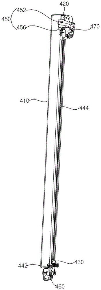
参照图13,气流变换器400包括:引导板410(guide board),配置于塔,向吹风间隙105凸出;一对板引导件420、430,安装于引导板410,变更引导板410的配置;一对驱动齿轮440、442,可旋转地配置于第一塔110或第二塔120内侧,与一对板引导件420、430啮合;轴444,连接一对驱动齿轮440、442;以及驱动马达470,与一对驱动齿轮440、442中的一个连接,提供驱动力。Referring to Fig. 13, the air flow converter 400 includes: a guide board 410 (guide board), configured on the tower, protruding to the
参照图13,气流变换器400包括一对支撑件450、460,所述一对支撑件450、460固定配置在第一塔110或第二塔120内侧,并且引导一对板引导件420、430各自的移动。一对支撑件450、460在轴444的上端和下端分别接触,并且能够支撑轴444的旋转。气流变换器400通过与驱动马达470连接来旋转,并且可以包括马达齿轮472,所述马达齿轮472配置为与一对驱动齿轮440、442中的一个啮合。Referring to FIG. 13 , the air flow converter 400 includes a pair of
引导板410可以隐藏于塔的内部或向吹风间隙105凸出。引导板410可以由透明的材质形成。The
参照图13,一对板引导件420、430包括配置于引导板410的上端部的上引导件420和配置于引导板410的下端部的下引导件430。一对驱动齿轮440、442包括配置为与上引导件420啮合的上齿轮440和配置为与下引导件430啮合的下齿轮442。一对支撑件450、460包括引导上引导件420的移动的上支撑件450和引导下引导件430的移动的下支撑件460。Referring to FIG. 13 , a pair of plate guides 420 and 430 includes an
参照图14,上引导件420与上支撑件450连接,并且通过与上齿轮440啮合来移动。参照图18,下引导件430与下支撑件460连接,并且通过与下齿轮442啮合来移动。Referring to FIG. 14 , the
参照图15,上引导件420包括:上板安装部422,使上引导件420固定于引导板410的一侧;上板齿轮424,与上齿轮440啮合,变更上引导件420的配置;以及上引导筋426,插入到形成于上支撑件450的上引导槽(未图示)中以引导上引导件420的移动。15, the
参照图15,上板安装部422朝上板齿轮424的上侧和下侧方向延伸。在上板安装部422形成有上紧固孔422a、422b,以与引导板410连接。上紧固孔422a、422b可以包括在上下方向上隔开配置的一对。在一对上紧固孔422a、422b之间配置有上板齿轮424。在一对上紧固孔422a、422b之间配置有上引导筋426。上引导件420和引导板410可以通过一对上紧固孔422a、422b而被紧固。因此,引导板410的配置可以随着上引导件420的移动而变更。上板安装部422可以配置在上板齿轮424的上侧和下侧。Referring to FIG. 15 , the upper
参照图15,上板齿轮424向上板安装部422的下侧延伸,并且在面向引导板410的相反面配置有与上齿轮440啮合的齿轮。形成于上板齿轮424的齿轮可以呈齿条形状。即,上板齿轮424和上齿轮440可以是齿条和小齿轮结构。因此,上板齿轮424可以随着上齿轮440的旋转变更引导板410的配置。Referring to FIG. 15 , the
参照图15,上引导筋426可以配置在上板安装部422和上板齿轮424之间。上引导筋426可以具有从形成上板齿轮424面凸出的结构。上引导筋426包括:上水平筋426a,在上板齿轮424和上板安装部422之间向上支撑件450的配置方向凸出;以及上垂直筋426b,从上水平筋426a的端部向上侧方向凸出。上垂直筋426b可以配置为插入到上支撑件450的上引导槽(未图示)中。Referring to FIG. 15 , the
当俯视时,上垂直筋426b可以呈具有与引导板410的曲率中心相同的曲率中心的曲面形状。The upper
在上支撑件450形成有上引导槽,所述上引导槽形成为引导上引导筋426的移动。上支撑件450固定配置在第一塔110或第二塔120的内侧。参照图16,上支撑件450可以包括固定在第一塔110或第二塔120的内侧的上壳体安装部454。An upper guide groove is formed in the
参照图16,上支撑件450包括:上固定主体452,安装在第一塔110或第二塔120的内侧;以及上紧固主体456,与上固定主体452结合,驱动马达470安装于该上紧固主体456。16, the
上固定主体452和上紧固主体456彼此结合。上固定主体452配置在上紧固主体456的上侧。上紧固主体456包括支撑上引导件420的上水平筋426a的上支撑板457,上固定主体452形成有引导上垂直筋426b的移动的上引导槽。上引导槽可以限制上垂直筋426b的移动范围。The
参照图16,在上紧固主体456的下侧安装有驱动马达470。驱动马达470固定配置在上紧固主体456的下侧。参照图16至图17,在上紧固主体456的下部面配置有固定驱动马达470的马达安装部458,和使轴444的一端插入的上轴安装部459。上轴安装部459可以形成有上轴槽459a,轴444的上端可以插入到所述上轴槽459a并旋转。Referring to FIG. 16 , a driving
在轴444的上端部配置有上齿轮440。上齿轮440固定配置于轴444。因此,轴444可以随着上齿轮440的旋转而一起旋转。An
参照图14,以与地面垂直形成的假想的轴Z为基准,轴444可以配置为倾斜规定角度θ。轴444可以倾斜地配置为与在第一内侧壁115或第二内侧壁125形成的第一板狭缝119或第二板狭缝129所形成的方向对应。Referring to FIG. 14 , the
上齿轮440配置为与连接于驱动马达470的马达齿轮472啮合。另外,在上齿轮440的一侧通过与马达齿轮472啮合而旋转时,上齿轮440的另一侧可以通过与上引导件420的上板齿轮424啮合来变更上板齿轮424的配置。另外,上齿轮440可以在通过与马达齿轮472啮合而旋转时,通过使轴444旋转而使配置于轴444的下端部的下齿轮442旋转。The
参照图18,下引导件430与下支撑件460连接,并且通过与下齿轮442啮合来移动。下引导件430与下支撑件460连接,并且通过与下齿轮442啮合来移动。Referring to FIG. 18 , the
参照图19,下引导件430包括:下板安装部432,使下引导件430固定于引导板410的一侧;下板齿轮434,与下齿轮442啮合,变更下引导件430的配置;以及下引导筋436,插入到形成于下支撑件460的下引导槽462a,引导下引导件430的移动。Referring to FIG. 19 , the
参照图19,下板安装部432沿下板齿轮434的上下方向延伸。下板安装部432形成有复数个下紧固孔432a,以与引导板410连接。复数个下紧固孔432a可以以下板齿轮434为基准而配置于上下侧。下引导件430和引导板410可以通过复数个下紧固孔432a中的至少一个而被紧固。因此,引导板410的配置可以随着下引导件430的移动而变更。下板安装部432可以配置在下板齿轮434的上侧和下侧。Referring to FIG. 19 , the lower
参照图19,下板齿轮434可以配置于在下板安装部432的沿上下方向形成的复数个下紧固孔432a之间。在下板齿轮434的面向引导板410的面的相反面配置有与下齿轮442啮合的齿条。下板齿轮434和下齿轮442可以是齿条和小齿轮结构。因此,下板齿轮434可以随着下齿轮442的旋转而沿下板齿轮434所形成的方向移动。Referring to FIG. 19 , the
下引导筋436可以在下板安装部432的下端部延伸。下引导筋436可以具有朝形成有下板齿轮434的面的相反面延伸的结构。即,上引导筋426和下引导筋436具有朝彼此相反的方向凸出的结构。The
下引导筋436包括:下水平筋436a,从下板安装部432的下端部朝下支撑件460的配置方向凸出;以及下垂直筋436b,从下水平筋436a的端部沿上下方向凸出。下水平筋436a朝引导板410的方向凸出。The
下垂直筋436b可以配置为插入到下支撑件460的下引导槽462a。下垂直筋436b包括:上筋436b2,从下水平筋436a的端部向上侧延伸;以及下筋436b1,从下水平筋436a的端部向下侧延伸。The lower
当俯视时,下垂直筋436b可以呈具有与引导板410的曲率中心相同的曲率中心的曲面形状。The lower
参照图20至图21,下支撑件460形成有下引导槽462a,所述下引导槽462a形成为引导下引导筋436的移动。下引导槽462a可以包括:下引导槽462a,下筋436b1插入到该下引导槽462a;以及追加引导槽(未图示),形成为使上筋436b2插入。Referring to FIGS. 20 to 21 , the
下支撑件460固定配置在第一塔110或第二塔120的内侧。下支撑件460可以包括固定在第一塔110或第二塔120的内侧的下壳体安装部464。The
下支撑件460包括安装于第一塔110或第二塔120的内侧的下固定主体462。The
下固定主体462包括支撑下引导件430的下水平筋436a的下支撑板465。在下固定主体462形成有下引导槽462a,所述下引导槽462a形成为引导下引导筋436的移动。下固定主体462包括引导壁463,所述引导壁463防止下引导筋436朝垂直于下引导件430的移动方向的方向移动。以下引导槽462a为基准,引导壁463配置在下轴安装部466的相反方向。引导壁463具有与上筋436b2的凸出的高度对应地向上侧凸出的结构。因此,在下引导筋436插入到下引导槽462a的情况下,下筋436b1可以配置于下引导槽462a,上筋436b2可以配置为面向引导壁463。The
上引导筋426和下引导筋436可以向彼此不同的方向延伸。The
参照图15,上引导筋426的上水平筋426a朝远离引导板410的方向延伸,参照图19,下引导筋436的下水平筋436a朝引导板410的方向延伸。Referring to FIG. 15 , the upper
另外,参照图15,上引导筋426的上垂直筋426b朝上侧方向延伸,参照图19,下引导筋436的下垂直筋436b朝下侧方向延伸。具体而言,下垂直筋436b的下筋436b1向下侧方向延伸。因此,上引导槽向上侧形成,下引导槽462a向下侧形成。15, the upper
下引导槽462a可以限制下垂直筋436b的移动范围。下固定主体462配置有下轴安装部466,轴444的另一端插入到该下轴安装部466。下轴安装部466形成有下轴槽466a,轴444的下端能够插入到该下轴槽466a并旋转。The
以上对本发明的优选实施例进行了图示和说明,但是本发明并不限定于以上所述的特定的实施例,在不背离权利要求书中主张的本发明的主旨的范围内,本领域的一般技术人员能够对其进行多种变形实施是显而易见的,并且这样的变形实施不应脱离本发明的技术思想或前景而单独地加以理解。The preferred embodiments of the present invention have been illustrated and described above, but the present invention is not limited to the above-described specific embodiments, and within the scope of not departing from the gist of the present invention claimed in the claims, those skilled in the art It is obvious that those skilled in the art can carry out various modifications, and such modifications should not be understood separately without departing from the technical idea or prospect of the present invention.
Claims (14)
Applications Claiming Priority (2)
| Application Number | Priority Date | Filing Date | Title |
|---|---|---|---|
| KR1020210117647A KR102572842B1 (en) | 2021-09-03 | 2021-09-03 | Blower |
| KR10-2021-0117647 | 2021-09-03 |
Publications (1)
| Publication Number | Publication Date |
|---|---|
| CN115750466A true CN115750466A (en) | 2023-03-07 |
Family
ID=83151908
Family Applications (1)
| Application Number | Title | Priority Date | Filing Date |
|---|---|---|---|
| CN202211054597.9A Pending CN115750466A (en) | 2021-09-03 | 2022-08-31 | Air blower |
Country Status (4)
| Country | Link |
|---|---|
| US (2) | US11808275B2 (en) |
| EP (1) | EP4144997A1 (en) |
| KR (4) | KR102572842B1 (en) |
| CN (1) | CN115750466A (en) |
Families Citing this family (1)
| Publication number | Priority date | Publication date | Assignee | Title |
|---|---|---|---|---|
| EP4219951B1 (en) | 2020-05-14 | 2024-12-25 | LG Electronics Inc. | Blower |
Citations (5)
| Publication number | Priority date | Publication date | Assignee | Title |
|---|---|---|---|---|
| CN203614369U (en) * | 2012-11-28 | 2014-05-28 | 拉斯科控股公司 | Portable pneumatic device |
| US20150017028A1 (en) * | 2013-07-09 | 2015-01-15 | Dyson Technology Limited | Fan assembly |
| US20180306452A1 (en) * | 2015-10-23 | 2018-10-25 | Samsung Electronics Co., Ltd. | Air conditioner |
| CN109538450A (en) * | 2019-01-29 | 2019-03-29 | 杭州坦布科技有限公司 | A kind of bladeless fan |
| WO2021107696A1 (en) * | 2019-11-28 | 2021-06-03 | Lg Electronics Inc. | Air conditioner |
Family Cites Families (28)
| Publication number | Priority date | Publication date | Assignee | Title |
|---|---|---|---|---|
| KR100365591B1 (en) * | 2000-06-12 | 2002-12-26 | 삼성전자 주식회사 | Opening and closing apparatus for air discharge port of air conditioner |
| KR20080010683A (en) | 2006-07-27 | 2008-01-31 | 주식회사 대우일렉트로닉스 | Wall-mounted air conditioner with liftable flow guide unit |
| KR101328937B1 (en) | 2007-01-26 | 2013-11-14 | 엘지전자 주식회사 | Air conditioner |
| KR101370271B1 (en) | 2009-03-04 | 2014-03-04 | 다이슨 테크놀러지 리미티드 | fan |
| GB0903682D0 (en) | 2009-03-04 | 2009-04-15 | Dyson Technology Ltd | A fan |
| US20120051884A1 (en) * | 2010-08-28 | 2012-03-01 | Zhongshan Longde Electric Industries Co., Ltd. | Air blowing device |
| CN203453146U (en) * | 2013-09-17 | 2014-02-26 | 应辉 | Nozzle device of bladeless fan |
| JP5964873B2 (en) * | 2014-02-19 | 2016-08-03 | 株式会社シーエー産商 | Fanless fan |
| KR20150144354A (en) * | 2014-06-16 | 2015-12-28 | 한온시스템 주식회사 | Air conditioner for vehicle |
| KR101516364B1 (en) * | 2014-12-31 | 2015-05-04 | 엘지전자 주식회사 | Air conditioner |
| CN104848508B (en) * | 2015-04-29 | 2017-12-12 | 广东美的制冷设备有限公司 | Air conditioner |
| CN105042695B (en) * | 2015-07-31 | 2017-09-19 | 芜湖美智空调设备有限公司 | Cabinet air-conditioner guider and through-flow cabinet air-conditioner |
| WO2017069437A1 (en) * | 2015-10-23 | 2017-04-27 | 삼성전자주식회사 | Air conditioner |
| CN106705212A (en) * | 2015-11-13 | 2017-05-24 | 青岛海尔空调器有限总公司 | Air conditioner indoor unit |
| BR112018073722A2 (en) * | 2016-05-18 | 2019-02-26 | De' Longhi Appliances S.R.L. Con Unico Socio | fan |
| CN206247479U (en) | 2016-08-31 | 2017-06-13 | 芜湖美智空调设备有限公司 | A kind of air conditioner room unit |
| CN106642311B (en) * | 2016-09-19 | 2022-05-27 | 珠海格力电器股份有限公司 | Air conditioner and control method thereof |
| CN206877265U (en) * | 2017-06-26 | 2018-01-12 | 华北电力大学(保定) | A kind of Novel bladeless fan radiator for high-performance CPU |
| KR20190025443A (en) | 2017-09-01 | 2019-03-11 | 엘지전자 주식회사 | Flow generator |
| JP6934598B2 (en) * | 2017-09-27 | 2021-09-15 | パナソニックIpマネジメント株式会社 | Blower, airflow supply method and airflow provision program |
| GB2568979A (en) * | 2017-12-01 | 2019-06-05 | Dyson Technology Ltd | A fan assembly |
| KR102151236B1 (en) * | 2018-10-18 | 2020-09-02 | 엘지전자 주식회사 | Humidifying air cleaner |
| CN209083703U (en) * | 2018-11-29 | 2019-07-09 | 浙江优美莱智能科技有限公司 | A kind of fan that nozzle is relatively independent |
| GB201900025D0 (en) * | 2019-01-02 | 2019-02-13 | Dyson Technology Ltd | A fan assembly |
| KR20200089362A (en) * | 2019-01-16 | 2020-07-27 | 주식회사 위니아딤채 | Air conditioner |
| CN110701676A (en) * | 2019-11-08 | 2020-01-17 | 海信(山东)空调有限公司 | Indoor unit of air conditioner |
| CN111322701A (en) * | 2020-04-03 | 2020-06-23 | 杰马科技(中山)有限公司 | bladeless cooling fan |
| US11629727B2 (en) * | 2020-11-10 | 2023-04-18 | Airmate Electrical (Jiu Jiang) Co., Ltd | Bladeless fan with multiple air ducts |
-
2021
- 2021-09-03 KR KR1020210117647A patent/KR102572842B1/en active Active
-
2022
- 2022-08-30 US US17/898,575 patent/US11808275B2/en active Active
- 2022-08-31 EP EP22193201.5A patent/EP4144997A1/en active Pending
- 2022-08-31 CN CN202211054597.9A patent/CN115750466A/en active Pending
-
2023
- 2023-06-20 KR KR1020230078590A patent/KR102713137B1/en active Active
- 2023-10-02 US US18/375,653 patent/US12313077B2/en active Active
-
2024
- 2024-09-27 KR KR1020240131533A patent/KR20240148780A/en active Pending
- 2024-10-30 KR KR1020240151258A patent/KR20240160072A/en active Pending
Patent Citations (5)
| Publication number | Priority date | Publication date | Assignee | Title |
|---|---|---|---|---|
| CN203614369U (en) * | 2012-11-28 | 2014-05-28 | 拉斯科控股公司 | Portable pneumatic device |
| US20150017028A1 (en) * | 2013-07-09 | 2015-01-15 | Dyson Technology Limited | Fan assembly |
| US20180306452A1 (en) * | 2015-10-23 | 2018-10-25 | Samsung Electronics Co., Ltd. | Air conditioner |
| CN109538450A (en) * | 2019-01-29 | 2019-03-29 | 杭州坦布科技有限公司 | A kind of bladeless fan |
| WO2021107696A1 (en) * | 2019-11-28 | 2021-06-03 | Lg Electronics Inc. | Air conditioner |
Also Published As
| Publication number | Publication date |
|---|---|
| US12313077B2 (en) | 2025-05-27 |
| KR20240160072A (en) | 2024-11-08 |
| KR20230034639A (en) | 2023-03-10 |
| KR20240148780A (en) | 2024-10-11 |
| KR20230098109A (en) | 2023-07-03 |
| KR102713137B1 (en) | 2024-10-02 |
| US20240026890A1 (en) | 2024-01-25 |
| US11808275B2 (en) | 2023-11-07 |
| KR102572842B1 (en) | 2023-08-29 |
| EP4144997A1 (en) | 2023-03-08 |
| US20230071183A1 (en) | 2023-03-09 |
Similar Documents
| Publication | Publication Date | Title |
|---|---|---|
| KR102800258B1 (en) | Air cean fan | |
| CN115750466A (en) | Air blower | |
| KR102622929B1 (en) | Blower | |
| CN115726993A (en) | Air blower | |
| EP4332383A2 (en) | Blower | |
| KR102658126B1 (en) | Air cean fan | |
| KR102800260B1 (en) | Air cean fan | |
| KR102879893B1 (en) | Air cean fan | |
| KR102429658B1 (en) | Air cean fan | |
| KR102619416B1 (en) | Air clean fan | |
| EP4530475A1 (en) | Blower | |
| CN120813772A (en) | Blower fan | |
| CN115726992A (en) | Blower | |
| HK40054480B (en) | Blower |
Legal Events
| Date | Code | Title | Description |
|---|---|---|---|
| PB01 | Publication | ||
| PB01 | Publication | ||
| SE01 | Entry into force of request for substantive examination | ||
| SE01 | Entry into force of request for substantive examination |