CN115695667A - Information processing apparatus, control method thereof, and storage medium - Google Patents
Information processing apparatus, control method thereof, and storage medium Download PDFInfo
- Publication number
- CN115695667A CN115695667A CN202211223221.6A CN202211223221A CN115695667A CN 115695667 A CN115695667 A CN 115695667A CN 202211223221 A CN202211223221 A CN 202211223221A CN 115695667 A CN115695667 A CN 115695667A
- Authority
- CN
- China
- Prior art keywords
- character
- character string
- scanned image
- displayed
- file name
- Prior art date
- Legal status (The legal status is an assumption and is not a legal conclusion. Google has not performed a legal analysis and makes no representation as to the accuracy of the status listed.)
- Pending
Links
Images


Classifications
-
- H—ELECTRICITY
- H04—ELECTRIC COMMUNICATION TECHNIQUE
- H04N—PICTORIAL COMMUNICATION, e.g. TELEVISION
- H04N1/00—Scanning, transmission or reproduction of documents or the like, e.g. facsimile transmission; Details thereof
- H04N1/0035—User-machine interface; Control console
- H04N1/00405—Output means
- H04N1/00408—Display of information to the user, e.g. menus
- H04N1/00411—Display of information to the user, e.g. menus the display also being used for user input, e.g. touch screen
-
- H—ELECTRICITY
- H04—ELECTRIC COMMUNICATION TECHNIQUE
- H04N—PICTORIAL COMMUNICATION, e.g. TELEVISION
- H04N1/00—Scanning, transmission or reproduction of documents or the like, e.g. facsimile transmission; Details thereof
- H04N1/00912—Arrangements for controlling a still picture apparatus or components thereof not otherwise provided for
- H04N1/00938—Software related arrangements, e.g. loading applications
-
- G—PHYSICS
- G06—COMPUTING; CALCULATING OR COUNTING
- G06F—ELECTRIC DIGITAL DATA PROCESSING
- G06F3/00—Input arrangements for transferring data to be processed into a form capable of being handled by the computer; Output arrangements for transferring data from processing unit to output unit, e.g. interface arrangements
- G06F3/01—Input arrangements or combined input and output arrangements for interaction between user and computer
- G06F3/048—Interaction techniques based on graphical user interfaces [GUI]
- G06F3/0481—Interaction techniques based on graphical user interfaces [GUI] based on specific properties of the displayed interaction object or a metaphor-based environment, e.g. interaction with desktop elements like windows or icons, or assisted by a cursor's changing behaviour or appearance
- G06F3/04817—Interaction techniques based on graphical user interfaces [GUI] based on specific properties of the displayed interaction object or a metaphor-based environment, e.g. interaction with desktop elements like windows or icons, or assisted by a cursor's changing behaviour or appearance using icons
-
- G—PHYSICS
- G06—COMPUTING; CALCULATING OR COUNTING
- G06F—ELECTRIC DIGITAL DATA PROCESSING
- G06F3/00—Input arrangements for transferring data to be processed into a form capable of being handled by the computer; Output arrangements for transferring data from processing unit to output unit, e.g. interface arrangements
- G06F3/01—Input arrangements or combined input and output arrangements for interaction between user and computer
- G06F3/048—Interaction techniques based on graphical user interfaces [GUI]
- G06F3/0481—Interaction techniques based on graphical user interfaces [GUI] based on specific properties of the displayed interaction object or a metaphor-based environment, e.g. interaction with desktop elements like windows or icons, or assisted by a cursor's changing behaviour or appearance
- G06F3/0482—Interaction with lists of selectable items, e.g. menus
-
- G—PHYSICS
- G06—COMPUTING; CALCULATING OR COUNTING
- G06F—ELECTRIC DIGITAL DATA PROCESSING
- G06F3/00—Input arrangements for transferring data to be processed into a form capable of being handled by the computer; Output arrangements for transferring data from processing unit to output unit, e.g. interface arrangements
- G06F3/01—Input arrangements or combined input and output arrangements for interaction between user and computer
- G06F3/048—Interaction techniques based on graphical user interfaces [GUI]
- G06F3/0484—Interaction techniques based on graphical user interfaces [GUI] for the control of specific functions or operations, e.g. selecting or manipulating an object, an image or a displayed text element, setting a parameter value or selecting a range
- G06F3/04845—Interaction techniques based on graphical user interfaces [GUI] for the control of specific functions or operations, e.g. selecting or manipulating an object, an image or a displayed text element, setting a parameter value or selecting a range for image manipulation, e.g. dragging, rotation, expansion or change of colour
-
- G—PHYSICS
- G06—COMPUTING; CALCULATING OR COUNTING
- G06F—ELECTRIC DIGITAL DATA PROCESSING
- G06F3/00—Input arrangements for transferring data to be processed into a form capable of being handled by the computer; Output arrangements for transferring data from processing unit to output unit, e.g. interface arrangements
- G06F3/01—Input arrangements or combined input and output arrangements for interaction between user and computer
- G06F3/048—Interaction techniques based on graphical user interfaces [GUI]
- G06F3/0487—Interaction techniques based on graphical user interfaces [GUI] using specific features provided by the input device, e.g. functions controlled by the rotation of a mouse with dual sensing arrangements, or of the nature of the input device, e.g. tap gestures based on pressure sensed by a digitiser
- G06F3/0488—Interaction techniques based on graphical user interfaces [GUI] using specific features provided by the input device, e.g. functions controlled by the rotation of a mouse with dual sensing arrangements, or of the nature of the input device, e.g. tap gestures based on pressure sensed by a digitiser using a touch-screen or digitiser, e.g. input of commands through traced gestures
- G06F3/04883—Interaction techniques based on graphical user interfaces [GUI] using specific features provided by the input device, e.g. functions controlled by the rotation of a mouse with dual sensing arrangements, or of the nature of the input device, e.g. tap gestures based on pressure sensed by a digitiser using a touch-screen or digitiser, e.g. input of commands through traced gestures for inputting data by handwriting, e.g. gesture or text
-
- G—PHYSICS
- G06—COMPUTING; CALCULATING OR COUNTING
- G06F—ELECTRIC DIGITAL DATA PROCESSING
- G06F3/00—Input arrangements for transferring data to be processed into a form capable of being handled by the computer; Output arrangements for transferring data from processing unit to output unit, e.g. interface arrangements
- G06F3/01—Input arrangements or combined input and output arrangements for interaction between user and computer
- G06F3/048—Interaction techniques based on graphical user interfaces [GUI]
- G06F3/0487—Interaction techniques based on graphical user interfaces [GUI] using specific features provided by the input device, e.g. functions controlled by the rotation of a mouse with dual sensing arrangements, or of the nature of the input device, e.g. tap gestures based on pressure sensed by a digitiser
- G06F3/0488—Interaction techniques based on graphical user interfaces [GUI] using specific features provided by the input device, e.g. functions controlled by the rotation of a mouse with dual sensing arrangements, or of the nature of the input device, e.g. tap gestures based on pressure sensed by a digitiser using a touch-screen or digitiser, e.g. input of commands through traced gestures
- G06F3/04886—Interaction techniques based on graphical user interfaces [GUI] using specific features provided by the input device, e.g. functions controlled by the rotation of a mouse with dual sensing arrangements, or of the nature of the input device, e.g. tap gestures based on pressure sensed by a digitiser using a touch-screen or digitiser, e.g. input of commands through traced gestures by partitioning the display area of the touch-screen or the surface of the digitising tablet into independently controllable areas, e.g. virtual keyboards or menus
-
- G—PHYSICS
- G06—COMPUTING; CALCULATING OR COUNTING
- G06F—ELECTRIC DIGITAL DATA PROCESSING
- G06F40/00—Handling natural language data
- G06F40/10—Text processing
- G06F40/166—Editing, e.g. inserting or deleting
-
- G—PHYSICS
- G06—COMPUTING; CALCULATING OR COUNTING
- G06F—ELECTRIC DIGITAL DATA PROCESSING
- G06F40/00—Handling natural language data
- G06F40/10—Text processing
- G06F40/166—Editing, e.g. inserting or deleting
- G06F40/174—Form filling; Merging
-
- H—ELECTRICITY
- H04—ELECTRIC COMMUNICATION TECHNIQUE
- H04N—PICTORIAL COMMUNICATION, e.g. TELEVISION
- H04N1/00—Scanning, transmission or reproduction of documents or the like, e.g. facsimile transmission; Details thereof
- H04N1/00127—Connection or combination of a still picture apparatus with another apparatus, e.g. for storage, processing or transmission of still picture signals or of information associated with a still picture
- H04N1/00326—Connection or combination of a still picture apparatus with another apparatus, e.g. for storage, processing or transmission of still picture signals or of information associated with a still picture with a data reading, recognizing or recording apparatus, e.g. with a bar-code apparatus
-
- H—ELECTRICITY
- H04—ELECTRIC COMMUNICATION TECHNIQUE
- H04N—PICTORIAL COMMUNICATION, e.g. TELEVISION
- H04N1/00—Scanning, transmission or reproduction of documents or the like, e.g. facsimile transmission; Details thereof
- H04N1/0035—User-machine interface; Control console
- H04N1/00352—Input means
- H04N1/00384—Key input means, e.g. buttons or keypads
-
- H—ELECTRICITY
- H04—ELECTRIC COMMUNICATION TECHNIQUE
- H04N—PICTORIAL COMMUNICATION, e.g. TELEVISION
- H04N1/00—Scanning, transmission or reproduction of documents or the like, e.g. facsimile transmission; Details thereof
- H04N1/44—Secrecy systems
- H04N1/4406—Restricting access, e.g. according to user identity
- H04N1/4413—Restricting access, e.g. according to user identity involving the use of passwords, ID codes or the like, e.g. PIN
-
- H—ELECTRICITY
- H04—ELECTRIC COMMUNICATION TECHNIQUE
- H04N—PICTORIAL COMMUNICATION, e.g. TELEVISION
- H04N2201/00—Indexing scheme relating to scanning, transmission or reproduction of documents or the like, and to details thereof
- H04N2201/0077—Types of the still picture apparatus
- H04N2201/0094—Multifunctional device, i.e. a device capable of all of reading, reproducing, copying, facsimile transception, file transception
Abstract
The invention relates to an information processing apparatus, a control method thereof, and a storage medium. So that the user can easily perform partial editing of an undetermined file name or the like being displayed on the UI screen of the image processing apparatus. An editing UI screen that takes the character string selected by the user as an object is displayed.
Description
(this application is a divisional application of an application having an application date of 2020, 4/17/10, application No. 2020103056733 entitled "image processing apparatus and control method therefor, and storage medium")
Technical Field
The present technology relates to a character input technology.
Background
Conventionally, as a document management method, a method of converting a scanned image obtained by reading a document with a scanner into a file of a predetermined format and transmitting the file to a storage server on a network to save the file is widely used. Then, as a method of simply setting a file name to a scanned image, there is a method of causing a user to select a character region (text block) on the scanned image displayed in a preview by touching the character region. Japanese patent laid-open No. 2018-124656 discloses a technique of generating and displaying a file name by using a character string described at a specific position within a document and receiving user's editing of the file name in the case where a scanned image obtained by scanning the document coincides with a predefined image feature.
In the technique of japanese patent laid-open No. 2018-124656 described above, a plurality of character strings obtained from a specific position of a document are connected and presented to a user (displayed on a UI screen) in a state of a series of file names. Thus, a user who wishes to edit each character string that is part of a file name needs to edit by specifying the position and range of the editing target character string from the entire file name presented. That is, a lot of time and effort are required to partially edit the presented file name.
In order to cope with the above problems, the technique of the present invention has been developed. That is, the object is to enable a user to easily perform partial editing of an undetermined file name or the like being displayed on a UI screen.
Disclosure of Invention
An image processing apparatus according to the present invention includes: detecting a character region from a scanned image obtained by scanning a document; controlling to display a UI screen for setting an attribute to the scanned image, wherein the displayed UI screen includes an input field for displaying a character string corresponding to the selected character region as an attribute to be set, wherein in a case where an operation on the input field in a state where at least one character string is displayed is detected, a soft keyboard for modifying one character string specified from the displayed at least one character string based on the operation is displayed; and setting an attribute to the scanned image by using the character string displayed in the input field after modifying the specified one character string with the soft keyboard.
An image processing apparatus comprising: at least one memory for storing a program; and at least one processor configured to execute the program to perform: detecting a character region from a scanned image obtained by scanning a document; controlling to display a UI screen for setting an attribute to the scanned image, wherein the displayed UI screen includes an input field for displaying a character string corresponding to the selected character region as an attribute to be set, wherein in a case where an operation on the input field in a state where at least one character string is displayed is detected, a soft keyboard for modifying one character string specified from the displayed at least one character string based on the operation is displayed; and setting an attribute to the scanned image by using the character string displayed in the input field after modifying the specified one character string with the soft keyboard.
A control method of an image processing apparatus, the control method comprising: detecting a character region from a scanned image obtained by scanning a document; controlling to display a UI screen for setting an attribute to the scanned image, wherein the displayed UI screen includes an input field for displaying a character string corresponding to the selected character area as an attribute to be set, and wherein, in a case where an operation on the input field in a state where at least one character string is being displayed is detected, a soft keyboard for modifying one character string specified from the displayed at least one character string based on the operation is displayed; and setting an attribute to the scanned image by using the character string displayed in the input field after modifying the specified one character string with the soft keyboard.
A non-transitory computer-readable storage medium storing a program for causing a computer to perform: detecting a character region from a scanned image obtained by scanning a document; controlling to display a UI screen for setting an attribute to the scanned image, wherein the displayed UI screen includes an input field for displaying a character string corresponding to the selected character region as an attribute to be set, and wherein, in a case where an operation on the input field in a state where at least one character string is being displayed is detected, a soft keyboard for modifying one character string specified from the displayed at least one character string based on the operation is displayed; and setting an attribute to the scanned image by using the character string displayed in the input field after modifying the specified one character string with the soft keyboard.
Further features of the invention will become apparent from the following description of exemplary embodiments with reference to the attached drawings.
Drawings
Fig. 1 is a diagram showing the entire structure of an image processing system;
FIG. 2 is a block diagram showing a hardware configuration of the MFP;
fig. 3 is a block diagram showing the hardware configuration of the MFP cooperation server and the storage server;
fig. 4 is a block diagram showing a software configuration of an image processing system;
fig. 5 is a sequence diagram showing a processing flow of the entire image processing system;
fig. 6 is a diagram showing an example of a main menu screen;
fig. 7 is a diagram showing an example of a login screen;
fig. 8 is a diagram showing an example of a scan setting screen;
fig. 9A is a diagram showing an example of a request ID, and fig. 9B and 9C are each a diagram showing an example of a response to a query relating to a processing situation;
fig. 10 is a diagram showing an example of a file name setting screen;
fig. 11 is a diagram showing an example of a learning request;
FIG. 12 is a flowchart showing a flow of processing in the MFP;
fig. 13 is a diagram showing an example of a scanned image;
fig. 14 is a diagram showing an example of a filename condition setting screen;
fig. 15 is a diagram showing an example of a character recognition result;
FIG. 16 is a diagram showing an example of a similar business form determination result;
fig. 17 is a diagram showing an example of a scanned image;
fig. 18A and 18B are flowcharts showing the flow of the file name setting processing in the MFP;
fig. 19A and 19B are flowcharts showing a flow of file name setting processing in the MFP;
FIG. 20 is a diagram showing an initial display portion of a preview area;
fig. 21 is a diagram showing an example of a file name setting screen;
fig. 22 is a diagram showing an example of a soft keyboard;
fig. 23 is a diagram showing an example of a file name setting screen on which an operation guide is displayed;
fig. 24 is a diagram showing an example of a file name setting screen in the case of a touch operation on a character region; and
fig. 25 is a diagram showing an initial display portion of the preview area in the case where the initial magnification is adjusted.
Detailed Description
The present invention will be described in detail below according to preferred embodiments with reference to the accompanying drawings. The structures shown in the following embodiments are merely exemplary, and the present invention is not limited to the schematically shown structures.
[ first embodiment ]
< System Structure >
Fig. 1 is a diagram showing the entire structure of an image processing system according to the present embodiment. The image processing system includes an MFP (multifunction peripheral) 110 and server devices 120 and 130 that provide a cloud service on the internet. The MFP 110 is connected with the server devices 120 and 130 to be able to communicate via the internet.
The MFP 110 is an example of an information processing apparatus having a scanning function. The MFP 110 is a multifunction peripheral having a plurality of functions such as a print function and a BOX saving function in addition to a scan function. Both of the server devices 120 and 130 are each an example of an information processing device that provides a cloud service. The server device 120 of the present embodiment provides a cloud service to perform image analysis on a scanned image received from the MFP 110, and transmits a request from the MFP 110 to the server device 130 that provides other services, and so on. Hereinafter, the cloud service provided by the server apparatus 120 is referred to as "MFP cooperation service". The server device 130 provides a cloud service (hereinafter referred to as a "storage service") to save a file transmitted via the internet, and provides a saved file in response to a request from a web browser such as a mobile terminal (not shown), and the like. In the present embodiment, the server apparatus 120 that provides the MFP cooperation service is referred to as an "MFP cooperation server", and the server apparatus 130 that provides the storage service is referred to as a "storage server".
The structure of the image processing system 100 shown in fig. 1 is an example, and the structure is not limited thereto. For example, the MFP 110 may also have the function of the MFP cooperation server 120. Further, the MFP cooperation server 120 may be connected to the MFP 110 via a LAN (local area network) instead of the internet. Further, it is also possible to replace the storage server 130 with a mail server that performs a mail distribution service, and apply the system to a case where a scanned image of a document is transmitted by attaching the scanned image to a mail.
< hardware configuration of MFP >
Fig. 2 is a block diagram showing the hardware configuration of the MFP 110. The MFP 110 includes a control unit 210, an operation unit 220, a printer unit 221, a scanner unit 222, and a modem 223. The control unit 210 includes the following respective units 211 to 219, and controls the operation of the entire MFP 110. The CPU 211 reads various control programs (programs corresponding to various functions shown in a software configuration diagram to be described later) stored in the ROM 212 and executes the programs. The RAM 213 is used as a temporary storage area of the CPU 211 such as a main memory and a work area. In the present embodiment, one CPU 211 performs each process shown in a flowchart to be described later by using one memory (the RAM 213 or the HDD 214), but the present embodiment is not limited thereto. For example, it is also possible to perform each process by causing a plurality of CPUs and a plurality of RAMs or HDDs to cooperate with each other. The HDD 214 is a large-capacity storage unit configured to store image data and various programs. The operation unit I/F215 is an interface connecting the operation unit 220 and the control unit 210. The operation unit 220 is provided with a touch panel, a keyboard, and the like, and receives an operation/input/instruction of a user. The touch operation on the touch panel includes an operation by a human finger and an operation with a touch pen. The printer I/F216 is an interface connecting the printer unit 221 and the control unit 210. Image data for printing is transferred from the control unit 210 to the printer unit 221 via the printer I/F216, and printed on a printing medium such as paper. The scanner I/F217 is an interface connecting the scanner unit 222 and the control unit 210. The scanner unit 222 optically reads a document placed on an unillustrated document table or ADF (automatic document feeder) to generate scanned image data and inputs the data to the control unit 210 via a scanner I/F217. The scanned image data generated by the scanner unit 222 can be printed (copied and output) in the printer unit 221, saved in the HDD 214, and transmitted as a file to an external apparatus such as the MFP cooperation server 120, or the like. The modem I/F218 is an interface connecting the modem 223 and the control unit 210. The modem 223 communicates image data with a facsimile apparatus (not shown) on the PSTN by facsimile. The network I/F219 is an interface that connects the control unit 210 (MFP 110) to the LAN. The MFP 110 transmits the scanned image data to the MFP cooperation server 120 by using the network I/F219, and receives various data from the MFP cooperation server 120, and the like. The hardware configuration of the MFP 110 described above is an example, and the hardware configuration may include other configurations as necessary or may not have a part of the configuration.
< hardware configuration of Server apparatus >
Fig. 3 is a block diagram showing the hardware configuration of the MFP cooperation server 120/storage server 130. The MFP cooperation server 120 and the storage server 130 have a common hardware configuration including a CPU 311, a ROM 312, a RAM 313, an HDD 314, and a network I/F315. The CPU 311 controls the entire operation by reading a control program stored in the ROM 312 and performing various processes. The RAM 313 is used as a temporary storage area of the CPU 311 such as a main memory and a work area. The HDD 314 is a large-capacity storage unit configured to store image data and various programs. The network I/F315 is an interface connecting the control unit 310 to the internet. The MFP cooperation server 120 and the storage server 130 receive requests for various processes from other devices (the MFP 110 and the like) via the network I/F315, and return processing results corresponding to the requests.
< software architecture of image processing System >
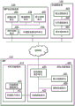
Fig. 4 is a block diagram showing a software configuration of the image processing system 100 according to the present embodiment. Hereinafter, software configurations corresponding to the roles of each of the MFP 110, the MFP cooperation server 120, and the storage server 130 constituting the image processing system 100 are explained in order. Hereinafter, a description will be given by narrowing various functions possessed by each device to functions related to processing of scanning a document and converting a scanned image into a file, and then saving the file in the storage server 130.
< MFP software Structure >, in the following description of the present invention
The functional modules of the MFP 110 are roughly divided into a native functional module 410 and an additional functional module 420. The native function module 410 is an application provided in the MFP 110 as a standard application, and the additional function module 420 is an application additionally installed in the MFP 110. The additional function module 420 is a Java (registered trademark) -based application, and addition of functions to the MFP 110 can be easily realized. In the MFP 110, other additional applications not shown may be installed.
The native function module 410 has a scan execution unit 411 and a scan image management unit 412. Further, the additional function module 420 has a display control unit 421, a scan control unit 422, a cooperation service request unit 423, and an image processing unit 424.
The display control unit 421 displays a user interface screen (UI screen) for receiving various user operations on the touch panel of the operation unit 220. Various user operations include, for example: an input of login authentication information for accessing the MFP cooperation server 120; scanning setting; providing a scanning start indication; setting a file name; and provision of file save instructions, etc.
The scan control unit 422 supplies an instruction to perform the scan processing to the scan execution unit 411 together with the scan setting information according to a user operation performed on the UI screen (for example, pressing a "start scan" button). The scan execution unit 411 causes the scanner unit 222 to perform a document reading operation via the scanner I/F217 and generate scanned image data according to an instruction to perform a scanning process from the scan control unit 422. The generated scanned image data is saved in the HDD 214 by the scanned image management unit 412. At this time, the scan control unit 422 is notified of information on a scan image identifier that uniquely represents the saved scan image data. The scanned image identifier is a number, a symbol, or a letter for uniquely identifying an image scanned in the MFP 110. The scan control unit 422 acquires the object scan image data converted into a file from the scan image management unit 412 by using the scan image identifier described above, for example. Then, the scan control unit 422 instructs the cooperation service request unit 423 to make a request to the MFP cooperation server 120 for processing necessary to transform the scanned image data into a file.
The cooperation service request unit 423 makes requests for various processes to the MFP cooperation server 120, and receives responses to the requests, and the like. The various processes include, for example, login authentication, scan image analysis, and scan image data transmission. For transmission and reception with the MFP cooperation server 120, communication protocols such as REST and SOAP are used.
The image processing unit 424 generates an image used on the UI screen displayed by the display control unit 421 by performing predetermined image processing on the scanned image data. Details of the predetermined image processing will be described later.
< software Structure of Server device >, computer program for executing the method, and computer-readable recording Medium having the program recorded thereon
First, a software configuration of the MFP cooperation server 120 is explained. The MFP cooperation server 120 has a request control unit 431, an image processing unit 432, a storage server access unit 433, a data management unit 434, and a display control unit 435. The request control unit 431 stands by in a state capable of receiving a request from an external apparatus, and instructs the image processing unit 432, the storage server access unit 433, and the data management unit 434 to perform predetermined processing according to the received request content. The image processing unit 432 performs image modification processing such as rotation and inclination correction, in addition to image analysis processing such as character area detection processing, character recognition processing, and similar document determination processing, on the scanned image data transmitted from the MFP 110. The storage server access unit 433 makes a request for processing of the storage server 130. The cloud service discloses various interfaces for saving a file in a storage server, and for acquiring the saved file and the like by using protocols such as REST and SOAP. The storage server access unit 433 makes a request to the storage server 130 by using the disclosed interface. The data management unit 434 stores and manages user information and various setting data and the like managed in the MFP cooperation server 120. The display control unit 435 receives a request from a web browser running on a PC or a mobile terminal (both not shown) connected via the internet, and returns screen structure information (HTML and CSS, etc.) necessary for screen display. The user can check the registered user information and change the scan setting, etc. via the screen displayed on the web browser.
Next, a software configuration of the storage server 130 will be described. The storage server 130 has a request control unit 441, a file management unit 442, and a display control unit 443. The request control unit 441 stands by in a state capable of receiving a request from an external device, and in the present embodiment, instructs the file management unit 442 to save a received file and read the saved file in accordance with a request from the MFP cooperation server 120. Then, the request control unit 441 returns a response corresponding to the request to the MFP cooperation server 120. The display control unit 443 receives a request from a web browser running on a PC or a mobile terminal (both not shown) connected via the internet, and returns screen configuration information (HTML, CSS, and the like) necessary for screen display. The user can check and acquire the saved file or the like via the screen displayed on the web browser.
< Process flow of the entire image processing System >
Fig. 5 is a sequence diagram of the flow of processing between the devices when a document is scanned in the MFP 110, the obtained scanned image is converted into a file, and the file is saved in the storage server. Fig. 6 is a diagram showing an example of a UI screen (hereinafter referred to as "home screen") of a main menu displayed at the time of startup of the MFP 110. By scanning a document and transforming the scanned image into a file, and installing a dedicated application required to use the cloud storage service in the MFP 110, a "scan and save in cloud storage" button 601 is displayed on the home screen 600. Then, in a case where the user presses a "scan and save in cloud storage" button 601 among the menu buttons displayed in the home screen 600, a series of processes shown in the sequence diagram of fig. 5 starts. Hereinafter, operations between the devices are explained in time series according to the sequence diagram of fig. 5. In the following description, the symbol "S" represents a step.
The MFP 110 displays, on the operation unit 220, a UI screen (hereinafter referred to as "login screen") on which information on login authentication for accessing the MFP cooperation server 120 is input (S501). Fig. 7 shows an example of a login screen. When the user inputs a user ID and a password registered in advance in the input fields 702 and 703 on the login screen 700, respectively, and presses the "login" button 701, a request for login authentication is transmitted to the MFP cooperation server 120 (S502).
The MFP cooperation server 120 that has received the request for login authentication performs authentication processing by using the user ID and the password included in the request (S503). In a case where it is checked by the result of the authentication that the user is a real user, the MFP cooperation server 120 returns an access token to the MFP 110. After that, the login user is specified by transmitting the access token together when the MFP 110 makes various requests to the MFP cooperation server 120. In the present embodiment, it is assumed that the login to the MFP cooperation server 120 is completed and the login to the storage server 130 is also completed. Thus, the user associates the user ID for using the MFP cooperation service and the user ID for using the storage service in advance via a web browser or the like of a PC (not shown) on the internet. Thus, when login authentication to the MFP cooperation server 120 is successful, login authentication to the storage server 130 is also completed at the same time, and the operation of logging in to the storage server 130 can be omitted. Then, the MFP cooperation server 120 can handle a request related to the storage service from the user who has logged in to the MFP cooperation server 120. In general, the login authentication method can be performed by using a known method (basic authentication, digest authentication, authentication using OAuth, and the like).
In the case where the login is completed, the MFP 110 displays a UI screen for scan setting (hereinafter referred to as "scan setting screen") on the operation unit 220 (S504). Fig. 8 shows an example of the scan setting screen. On the scan setting screen 800, there are a "start scan" button 801, a color setting column 802, and a resolution setting column 803. The "start scanning" button 801 is a button for giving an instruction to start scanning processing of a document (in the present embodiment, a business form such as a quotation and a bill is assumed) placed on the original table. In the color setting field 802, a color mode at the time of scanning is set. For example, the color setting column 802 is designed so that a color mode can be specified from among alternatives such as full color and monochrome. In the resolution setting field 803, the resolution at the time of scanning is set. For example, the resolution setting field 803 is designed so that the resolution can be specified from alternative items such as 600dpi and 1200 dpi. The setting items of the color mode and the resolution are only exemplary, and all of these items need not exist, or other setting items other than these items may exist. Further, the alternatives regarding color mode and resolution may also be limited to only the settings required for the storage service. The login user performs detailed condition setting of the scanning process via the scan setting screen 800 such as this. In a case where the user who has completed the scan setting sets a scan target document on the document table of the MFP 110 and presses the "start scan" button 801, scanning is performed (S505). Thereby, image data obtained by computerizing the paper document is generated. After the scan is completed, the MFP 110 transmits the image data obtained by the scan to the MFP cooperation server 120 together with an analysis request for the image data (S506).
In the MFP cooperation server 120 that has received the request to analyze the scanned image, the request control unit 431 instructs the image processing unit 432 to perform image analysis processing (S507). At this time, the request control unit 431 returns a request ID capable of uniquely specifying the received analysis request to the MFP 110. Fig. 9A shows an example of a request ID. On the other hand, the image processing unit 432 that has received the instruction to perform the analysis processing performs the analysis processing on the scanned image (S508). In this image analysis processing, processing to detect a character region (text block) present in a scanned image is first performed. For the detection of the character region, for example, a known method such as a method of extracting a rectangular region predicted as a character from an image binarized with a specific threshold value or the like can be applied. Next, optical Character Recognition (OCR) is performed on each character area detected by the character area detection processing. Then, a process (similar document determination process) is performed to determine whether or not the present scanning target business form is similar to the past scanning target business form. The judgment of the similar business form uses the arrangement information indicating at which position of the scanned image each character area existing within the scanned image is located. Specifically, the arrangement information on the past scanned image and the arrangement information on the present scanned image are compared, and it is determined whether the arrangement of the character regions is similar. This is based on the fact that: in the case where the configuration of the character area is similar, it can be predicted that the business form is created using the same format. The configuration information on past scanned images for judgment of similar business forms is accumulated by "business form learning processing" to be described later. The result obtained by the image analysis processing is transmitted to the request control unit 431. In the present embodiment, the similarity between the business forms is judged based only on the degree of similarity between the configurations of the character areas, but for example, it is also possible to specify the type of the business form (quotation and billing, etc.) based on the OCR result and judge the similarity by considering the obtained type information.
While the above-described image analysis processing is in progress, the MFP 110 periodically (for example, every several hundred milliseconds to every several milliseconds) makes an inquiry about the processing situation to the MFP cooperation server 120 by using the above-described request ID (S509 to S509'). This inquiry is repeatedly performed until a completion response of the image analysis processing from the MFP cooperation server 120 is acquired (S510). Upon receiving the inquiry about the processing situation, the MFP cooperation server 120 checks the progress situation of the image analysis processing corresponding to the request ID, and returns a response indicating that the processing is in progress in the case where the image analysis processing has not been completed (see fig. 9B). In the case where the image analysis processing is completed, the MFP cooperation server 120 returns a response indicating that the image analysis processing is completed (see fig. 9C). In the "status" of the response, a character string indicating the current processing situation is input, specifically, "processing" is input in the case where the processing is in progress in the MFP cooperation server 120, and "completed" is input in the case where the processing is completed. There are cases where a character string indicating another situation, such as "failed" in the case where the processing has failed, is input. As shown in fig. 9C, the response at the time of completion of the processing includes information on the analysis result of the scanned image and the like in addition to the situation information.
After receiving the process completion response, the MFP 110 makes a request for the result of the image analysis process to the MFP cooperation server 120 by using the URL indicating the storage destination of the image analysis result included in the response (S511). As URLs in this case, there are "ocrrresulturl" and "matchingtresulturl". Upon receiving the request, the request control unit 431 of the MFP cooperation server 120 returns result information about the image analysis processing.
Then, the MFP 110 displays a UI screen for setting a file name (hereinafter referred to as "file name setting screen") by using the acquired result information (S512). Fig. 10 shows an example of a file name setting screen. In a case where the user sets a file name and presses the send button 1007, the MFP 110 first sends a learning request including information on an input operation performed by the user when setting the file name (input information at the time of setting) to the MFP cooperation server 120 (S513). Fig. 11 shows an example of the learning request. The learning content is specified in "learning content" in which there are "rectInfoArray" relating to a character area used by a file name and "metadataArray" relating to metadata. In the "recatnfoarray", coordinate information on a character area used at the time of file name setting is input. In the "metadataArray", information on a character area corresponding to a character string used by a file name and information on a delimiter attached to the character string are input. The example of FIG. 11 shows that the filename structure is such that: the character string of the character area headed "fileRegion0", followed by the separator, and the character string of the character area ended "fileRegion1", and these three are arranged in this order.
In the MFP cooperation server 120 that has received the learning request, the request control unit 431 instructs the image processing unit 432 to perform the business form learning process (S514). Upon receiving the instruction, the image processing unit 432 saves the configuration information on each character region existing in the scanned image, and the input information (file name structure information) at the time of file name setting included in the learning request received in S513 (S515).
After that, the MFP 110 transmits a request to save the scanned image to the MFP cooperation server 120 together with the scanned image data and information such as the file name set at the time of conversion into a file (S516). In the MFP cooperation server 120 that has received the save request, the request control unit 431 returns a response indicating that the save request has been normally received to the MFP 110 in addition to starting the file generation process. The MFP 110 that received the response terminates the processing, and the state returns to the state in which the scan setting screen is displayed (S504). On the other hand, the MFP cooperation server 120 acquires information on a file format from scan settings registered in advance, and converts a scanned image into a file according to the file format (S517). At this time, the file name specified in the save request is attached to the generated file. The scanned image file thus generated is transmitted to the storage server and saved in the storage server (S518).
The above is the processing flow of the entire image processing system.
< details of MFP processing >
Subsequently, by focusing attention on the operation in the MFP 110, the processing in the case of using the storage service in the above-described image processing system is described in detail. Fig. 12 is a flowchart showing a flow of processing in the MFP 110. This series of processing is realized by the CPU 211 executing a control program stored in the HDD 214 in the control unit 210, and is started in response to pressing the "scan and save in cloud storage" button 601 on the home screen 600 described earlier. A detailed description is given below along with a flowchart shown in fig. 12. The symbol "S" above each process means a step.
In S1201, the display control unit 421 displays the aforementioned login screen 700. In a case where a user name and a password are input to the input fields 702 and 703, respectively, on the login screen 700, and it is detected that the "login" button 701 is pressed, the processing proceeds to S1202.
In S1202, the cooperation service request unit 423 transmits a request for login authentication to the MFP cooperation server 120. The cooperation service requesting unit 423 receives an access token from the MFP cooperation server 120 in a case where it is checked that the user is a real user through login authentication in the MFP cooperation server 120.
In S1203, in the MFP 110 that received the access token, the display control unit 421 displays the aforementioned scan setting screen 800 on the operation unit 220. In a case where the login user places a document on the document table and detects the pressing of the "start scanning" button 801, the display control unit 421 notifies the scanning control unit 422 of this.
In S1204, the scan control unit 422 having received the above notification instructs the scan execution unit 411 to perform the scan process. Upon receiving the instruction, the scan execution unit 411 scans the document placed on the document table. In the description of the flow, it is assumed that the description is given by taking a business form (more specifically, a quotation) as an example of a scanning object. Thereby, a scanned image of the quotation as shown in fig. 13 is obtained. The scanned image data generated by scanning is saved in the scanned image management unit 412, and an identifier capable of specifying a scanned image is notified to the display control unit 421. At this time, a message screen (not shown) indicating that scanning is in progress may also be displayed on the operation unit 220.
Next, in S1205, the cooperation service request unit 423 acquires the scanned image data via the scan control unit 422, and transmits the scanned image data to the MFP cooperation server 120 together with the analysis request. In the MFP cooperation server 120, the aforementioned image analysis processing is performed on the received scanned image data based on the analysis request. At this time, the request ID is returned from the request control unit 431 of the MFP cooperation server 120.
In S1206, the cooperation service request unit 423 that received the request ID transmits an acquisition request for the process status to the MFP cooperation server 120 together with the request ID. Based on the acquisition request, the MFP cooperation server 120 returns a response corresponding to the situation of progress of the image analysis processing specified by the request ID to the MFP 110.
In S1207, the cooperation service request section 423 returns to S1206 when the status in the received response indicates "processing" in progress. Then, after waiting until a predetermined time elapses, the cooperation service request unit 423 transmits an acquisition request for the process status to the MFP cooperation server 120 again. In the case where the status in the received response is "completed" indicating that the processing is completed, the process proceeds to S1208. Here, information on the image analysis result included in the response at the time of completion of the processing of the present embodiment is explained with reference to fig. 9C described earlier. As information on the image analysis result, there are three kinds of information of "ocrrresulturl", "matchingResultUrl", and "formKeys". The information "ocrreulturl" is information on a URL for acquiring a result of the OCR process in the image analysis process. The information "matchresulturl" is information on a URL for acquiring a result of the similar business form judgment processing of the image analysis processing. The information "formKeys" is information on setting values for setting attributes (such as a file name, metadata, and a folder path) to the scanned image, and is set in advance in the MFP cooperation server 120. The "formKeys" includes the following information.
Key: value uniquely representing set value set to scanned image
KeyType: value indicating type of set value of key
Value: initial value of set value (for example, "scan" representing scanned image)
Type: a value indicating the kind of a value input to the set value (e.g., "string" representing a character string, "number" representing a numerical value, date "representing a date, etc.)
displayName; display name in case of displaying setting screen on touch panel of MFP
Required: value indicating whether input of set value is indispensable
multiSelect: value indicating whether or not character strings of a plurality of character areas are used for file names
Seperator: content of separator of character string in case of connecting character strings using a plurality of character areas
AutoInput: value indicating whether or not automatic input of initial file name is performed
In fig. 9C, "formKeys" in the case of setting a file name to a scanned image is shown. By taking the case of fig. 9C as an example, how the respective values of "value", "displayName", "required", and "multiSelect" affect the file name setting screen displayed in the following S1209 (fig. 10) will be described. Now the contents of "value" are empty. In this case, the initial value is not displayed in the file name input field 1001 on the file name setting screen 1000. Further, "displayName" is "filename". In this case, as in the case of the file name setting screen 1000 of fig. 10, a character string indicating the "file name" of the set title or label is displayed in the upper part of the screen (in this example, with an empty character on a colored background). Further, "required" is "true". In this case, the "send" button 1007 cannot be pressed any more in a state where a character string is not input in the file name input field 1001. Further, "multiSelect" is "true". In this case, a plurality of character areas detected from the scanned image can be selected, and therefore, a file name connecting character strings corresponding to the respective character areas can be set. The above-described contents contained in "formKeys" are set by the user via the file name condition setting screen displayed by the display control unit 435 of the MFP cooperation server 120. Fig. 14 shows an example of a file name condition setting screen. A check box 1401 within the filename condition setting screen 1400 is used by the user to select whether to automatically input a filename by using information about character regions previously used at the time of filename setting of a scanned image. In the setting field 1402, in the case of using a plurality of character strings corresponding to a plurality of character regions for a file name, separators inserted between the character strings are set from alternatives (underline, hyphen, and the like) displayed in the drop-down list. Here, underlining is selected. At the initial display of the file name setting screen (fig. 10), the setting field 1403 is brought into an input state in advance, and a character string (initial file name) presented to the user as a candidate for a file name is set. The contents set on this file name condition setting screen 1400 are stored in the data management unit 434, and are referred to in the case of creating a response at the time of completion of the processing.
In S1208, the cooperation service requesting unit 423 accesses the URL included in the response when the processing is completed and acquires the image analysis result. In the example of fig. 9C, information is stored in "ocrrresulturl" and "matchingResultUrl", and thus the cooperation service request unit 423 accesses the two URLs and acquires the image analysis result. Table 1 below shows the coordinates of the character areas detected from the scanned image of fig. 13 and the character recognition results (recognized character strings) of the respective character areas.
TABLE 1

Then, fig. 15 shows the character recognition result for the scanned image in fig. 13 acquired by accessing "ocrreulturl". Here, "imageWidth" represents the number of pixels in the X direction (lateral direction) of the analysis target scanned image, and "imageHeight" represents the number of pixels in the Y direction (longitudinal direction) of the analysis target scanned image. In the "regions", coordinate information ("rect") about a character region detected from a scanned image and character string information ("Text") corresponding to the character region are included. In "rect", information for specifying the detected character area is included, "X" represents an X coordinate of the upper left corner of the character area, "Y" represents a Y coordinate of the upper left corner of the character area, "width" represents the number of pixels in the X (width) direction of the character area, and "height" represents the number of pixels in the Y (height) direction of the character area. Then, "text" represents information on a character string obtained by performing OCR processing on the character region specified by "rect". The information "rect" and "text" is included so as to correspond to all the character regions detected within the analysis object scanned image. However, in fig. 15, a part of these character regions is omitted.
Then, fig. 16 shows the similar business form judgment result for the scanned image of fig. 13 acquired by accessing "matchingResultUrl". In "matched", either "true" or "false" is input as a value indicating whether or not a scanned image similar to the scanned image of the analysis target of this time is found in the scanned images in the past by the similar business form determination processing described above. The case of a value of "true" indicates that the current scan object business form is similar to the previously scanned business form, and the case of "false" indicates that the current scan object business form is not similar to the previously scanned business form. In "formID", in the case where a similar business form is found, a value (ID value) uniquely representing a scanned image of a past similar business form is input. On the other hand, in a case where a similar business form is not found, a newly created ID value uniquely representing a scanned image of the business form for which the scan is performed this time is input. Then, in a case where input information (structural information about file names) at the time of file name setting for a scanned image of a business form for which a similar business form does not exist in the past is caused to be learned, a newly created ID value is used. In "matchscore", a value representing the coincidence rate is input in the case where similar business forms exist. The degree of similarity of the present embodiment represents the coincidence rate between the arrangement information on the character region in the past scanned image and the arrangement information on the character region in the present scanned image with a real numerical value between 0 and 1, and this indicates that: the larger the value, the more similar the two. In the "recatnfoarray", information indicating a character area in the analysis target scanned image of this time, which corresponds to a character area used when the file name of the scanned image for the past similar business form is set, is input.
In the case of the example of fig. 16, for the scanned image of fig. 13 obtained by scanning the quotation, the file name is set by using two character strings (i.e., "quotation" and "kakka"), and learning of the input information is performed. Thereafter, the quotation created in the same format is scanned and the scanned image shown in fig. 17 is generated, and as a result of performing similar business form determination processing on the scanned image, it is determined that the scanned image is similar to the scanned image of fig. 13. Then, the example of fig. 16 shows a state in which information on a character region used at the time of file name setting for the scanned image of fig. 13 is stored as information on an automatic input target character region. Hereinafter, the processing until the result of the similar business form judgment processing shown in fig. 16 is obtained is explained.
As a premise, it is assumed that the learning result based on the previously described learning request of fig. 11 is saved in the data management unit 434. Then, in the similar business form determination process, of the character regions included in the scanned image of this time, a character region in which a part overlaps with the character region indicated by the coordinate information is specified by using the coordinate information on the character regions of the "quotation note" and "kakka", which are used at the time of the previous file name setting. Then, coordinate information on a part of the character area designated as overlapping and the character string of the character area are stored in "text" of "rectInfoArray". In "key", a value uniquely representing a character region used for automatic input of a file name is input. In the "region", coordinate information on a character region uniquely represented by the "key" and a character string obtained by OCR processing on the character region are stored. Then, in "rect", information for specifying the character region uniquely represented by "key" is included. In this case, "X" represents an X coordinate of the upper left corner of the character region, "Y" represents a Y coordinate of the upper left corner of the character region, "width" represents the number of pixels in the X (width) direction of the character region, and "height" represents the number of pixels in the Y (height) direction of the character region. Then, information on a character string obtained by performing OCR processing on the character region specified by "rect" is input in "text". In the "metadataArray", the order of character areas used when automatically inputting a file name and information indicating where a delimiter is inserted are stored. In the case where attribute information such as metadata is set in addition to the file name, in "recatunnoarray" and "metadataArray", necessary information is added. In "key", a value uniquely representing a set value set to a scanned image is stored. In "keyType", a value representing the type of the set value of "key" is stored. In the case of being used for a file name, "filename" is input in "key", and "filename" is input in "keyType". In "value", a character region for the value of "key" and information on a delimiter are stored. In the example of FIG. 16, the character string of the character area having the "key" of "fileRegion0" in "recanfoarray" is the first, the separator is the second, and the character string of the character area having the "key" of "fileRegion1" is the third. Then, the three are automatically input in the file name input field 1001 in this order and displayed as the initial file name.
In S1209, the display control unit 421 displays the aforementioned filename setting screen 1000 on the operation unit 220 so that the user can make a filename setting for the scanned image. Details of this file name setting processing will be described later.
In S1210, the cooperation service requesting unit 423 determines whether the file name automatic input is set and determines the next process by referring to the response to the request for the process status in S1206. Specifically, the collaboration service request unit 423 refers to the value of "autoInput" included in the response at the time of completion of the processing shown in fig. 9C described earlier, and in the case of "true" meaning that automatic input is performed, the processing proceeds to S1211. On the other hand, if "false" means that automatic input is not performed, the process proceeds to S1214.
In S1211, the cooperation service request unit 423 determines whether or not there is a scanned image similar to the scanned image of this time in the past based on the image analysis result acquired in S1208. Specifically, the collaboration service request unit 423 refers to the value of "matched" included in the result of the similar business form determination processing shown in fig. 16 described earlier, and in the case of "true" indicating that there is a similar scanned image in the scanned images in the past, the processing proceeds to S1212. On the other hand, in the case of "false" indicating that there is no similar scanned image, the process proceeds to S1214.
In S1212, the cooperation service requesting unit 423 determines whether the initial file name automatically input in the file name input field 1001 in the file name setting process of S1209 has been changed by the user. The changes in this case include, for example: changing a character area of the file name for this time to a character area different from the character area used in the initial file name; and add or delete delimiters; and so on. Then, this determination is made by comparing the value of "value" of "metadataArray" included in the result of the similar business form determination processing of fig. 16 with the information input in the file name input field 1001 after the file name setting is made on the scanned image of this time. As a result of this comparison, in the case where there is a difference, it is determined that the initial file name has been changed and the process proceeds to S1213, and in the case where both of them coincide with each other, it is determined that the initial file name has not been changed and the process proceeds to S1214. Regarding the top character string of the file name automatically input by "value" of "formKeys", even if the user deletes the character string, the process may proceed to S1214 without regarding that the input information has changed.
In S1213, the cooperation service request unit 423 transmits a learning request (see fig. 11 described earlier) for input information at the time of setting indicating the structure of the file name set for the scanned image of this time to the MFP cooperation server 120. As the "formId" included in the learning request in this case, the value of the "formId" included in the similar business form determination processing result of the image analysis result acquired in S1208 is used. In the example of fig. 16, "aaaaaaaa-ffff-49ab-acf8-55558888eeee" is input as the value of "formId", and thus the value is stored in the learning request. In addition, in the "leaningcontent", the content of input information used at the time of file name setting is stored. First, in the "recatnfoarray", coordinate information on a character area to which a character string used by a file name belongs is stored so as to correspond to the number of character areas. Then, in the "metadataArray", information on the character area and the delimiter used for the file name setting is stored. To explain the operation performed by the user at this time with reference to table 1 described earlier, first, the user touches "quotation" with number 1 in the preview area 1002 on the filename setting screen 1000. Next, the user touches "kakka having number 8", and finally presses the "send" button 1007. The MFP cooperation server 120 that has received the learning request accumulates input information based on a user operation such as this, and uses the accumulated input information in the next and subsequent image analysis processes. When a response indicating that the learning request is normally processed is received from the MFP cooperation server 120 after the learning request is transmitted, the process proceeds to S1214.
In S1214, the cooperation service requesting unit 423 associates the processing target scanned image data and the file name set in S1209 with each other, and transmits both to the MFP cooperation server 120. In the case where the transmission is completed, the process ends. In the present embodiment, the transmission of the scanned image data and its file name is performed last, but both may be transmitted to the MFP cooperation server 120 in parallel at the point in time of saving of the scanned image data by the scanned image management unit 412 after the completion of the scanning process.
The above is a processing flow in the case where the storage service focusing on the operation in the MFP 110 is used. In the above description, the following scenario is assumed: file name setting is performed when one scanned image obtained by scanning one quotation is converted into a file. However, the present embodiment is not limited to this, and the present embodiment may also be applied to a scene where file name setting is performed when a plurality of scanned images obtained by scanning a plurality of quotations are converted into files. In this case, a button to turn a page may also be provided in the filename setting screen 1000 so that a filename may also be set from a character region in the scanned image on the second page or the third page.
(File name setting processing)
Subsequently, the file name setting process performed by the display control unit 421 in S1209 described earlier is described in detail along with flowcharts shown in fig. 18A, 18B, 19A, and 19B.
In S1801, a file name (initial file name) displayed in the file name input field 1001 on the file name setting screen 1000 described earlier in the initial state is generated. The initial file name is generated by the following procedure. First, the display control unit 421 refers to the response when the aforementioned processing is completed, and sets a value to the head of the file name in the case where the value is input in "value" of "formKeys". For example, in a case where a character string of "scan" is input as "value" of "formKeys", the display control unit 421 sets "scan" to the beginning of the initial file name. Next, the display control unit 421 sets a predetermined character string according to the similar business form judgment result obtained by accessing "mathingResultUrl". That is, in the case where the value of "matched" is "true" and "matched score" is a numerical value (for example, 0.6 or more) greater than or equal to a predetermined value, the display control unit 421 sets the character string according to the file name structure specified by "value" of "metadataArray". Specifically, the display control unit 421 sets the character strings of the character areas specified by "rectInfoArray" according to the order specified in "value". In the example of the similar business form judgment result, the value "formatted" is "true" and "matchScore" is "0.74 ·", so this is a value greater than or equal to a predetermined value. Then, in "value" of "metadataArray", f is specifiedileRegion0 "is the first, segment" is the next, and fileRegion1 "is the last permutation. As a result, "quotation" as the value of "text" of "fileRegion0", "_ (underlined)" as the value of "partner" included in the process completion response, and "lower pellet company" as the value of "text" of "fileRegion1" are connected in this order. In this way, "quotation _ lower pellet press" is generated as the initial file name. In the case where a certain value (for example, "scan _") is input in "value" of "formKeys", the "scan _ quotation _ lower pellet company" obtained by adding "scan _" to the "quotation _ lower pellet company" is an initial file name. In the similar business form judgment result, in the case where the value of "matched" is "false" and "matched score" is a numerical value smaller than a predetermined value, the character string is regarded as the initial file name as it is under the condition that the character string is input in "value" of "formKeys". In addition, when a character string is not input in "value" of "formKeys", the initial file name (blank column) is not displayed. In the present embodiment, two values of the value of "matched" and the value of "matched score" are adopted (i.e., according to "metadataThe order of "value" of Array "is information specified in" rectInfoarray ") as a condition for initial file name generation. However, the condition is not limited thereto, and one of these results may also be adopted as the condition. For example, it is also possible to generate an initial file name by only taking the value of "matched" as "true" as a condition, or to generate a file name by only taking the value indicating the degree of similarity greater than or equal to a threshold value as a condition.
In S1802, when the scanned image is displayed in the preview area 1002 on the file name setting screen 1000 in the initial state, the scanned image is reduced in size (hereinafter referred to as initial magnification) to be displayed. To determine the initial magnification, a character recognition result acquired by accessing "ocrreulturl" is used. First, of all the character regions detected within the scanned image, the leftmost character region and the rightmost character region are found, respectively. In this case, the leftmost character region is a character region in which the value of the x coordinate is the minimum value among all the character regions. Further, the rightmost character region is a character region in which the sum of the value of the x coordinate and the value of the width of the character region is largest among all the character regions. Magnifications respectively causing the left side of the leftmost character area thus determined to coincide with the left side of the preview area 1002 and causing the right side of the rightmost character area to coincide with the right side of the preview area 1002 are determined as initial magnifications. In the case where the end of the specified character region is made to completely coincide with the end of the preview region, there is a possibility that the user cannot easily make a selection (press) on the condition that the character region is small, and therefore the initial magnification can also be determined by giving a margin of a predetermined amount. For example, the initial magnification is determined such that a margin corresponding to 10 pixels is secured between the left end of preview region 1002 and the left end of the character region displayed at the leftmost position within preview region 1002, and between the right end of preview region 1002 and the right end of the character region displayed at the rightmost position. Further, in the case where UI components such as various operation buttons and the like are displayed on the preview area 1002 in an overlapping manner, the initial magnification may also be determined so that the character area and the UI components do not overlap. Specifically, the initial magnification may also be determined such that the leftmost character region and the rightmost character region are both included within the width of the remaining region after subtracting the width of the UI component from the width of the preview region 1002. In the previously described example of the file name setting screen 1000 of fig. 10, three operation buttons (the enlargement button 1004, the reduction button 1005, and the restoration button 1006) are present within the preview area 1002, and therefore the initial magnification is determined so that the character area does not overlap with these buttons. Further, there is a case where header information or the like relating to the printing process is printed in the vicinity of the upper end, the lower end, the left end, and the right end of the scan-target business form, and the possibility that a character string of a character area corresponding to the header information such as this is adopted as a part of the file name is low. As a result, it is also possible to exclude character regions existing within a predetermined distance (for example, 50 pixels) from the upper end, lower end, left end, and right end of the scanned image when the leftmost character region and rightmost character region described above are found.
In S1803, it is determined which portion of the scanned image after enlargement/reduction at the initial magnification determined in S1802 is displayed in the initial state within the preview area 1002 on the file name setting screen 1000. In the scanned image after the enlargement/reduction at the magnification determined in S1802 described above, the width including the leftmost character area and the rightmost character area substantially matches the width of the preview area 1002. As a result, first, in the horizontal direction, a portion displayed in an initial state (hereinafter referred to as "initial display portion") is determined such that the leftmost character region and the rightmost character region are exactly included in the preview region 1002, for example, the left of the leftmost character region coincides with the left of the preview region 1002. Thereafter, the initial display portion in the vertical direction is determined such that the uppermost character region is located near the upper end of preview region 1002. At this time, in the case where the margin is taken into consideration in the determination of the initial magnification, it is sufficient to determine the initial display section by also taking the margin into consideration. For example, it is also possible to exclude a character area existing within a predetermined distance (for example, 50 pixels) from the upper end of the scanned image from the display object and determine the initial display portion so that a character area located at the uppermost position among character areas other than the character area is displayed at the upper end of the preview area 1002. Fig. 20 is a diagram showing an initial display portion determined for the scanned image in fig. 13. A line frame in fig. 20 indicates a range of the scanned image displayed in the initial state in the preview region 1002. As a result of determining the initial display portion as described above, there is a case where a character area of a character string for use for an initial file name under a condition that a similar business form exists and the initial file name is automatically input in the file name input field 1001 is not displayed in the preview area 1002. In this case, it is sufficient to determine the initial display portion so that the character area of the character string for use with the initial file name is displayed in the center of the preview area 1002. At this time, the character string constituting the initial file name automatically input in the file name input field 1001 and the character region of the character string used for the initial file name may be highlighted (for example, the colors of both are changed). Fig. 21 is an example of a file name setting screen 1000 in the case where a character string of "kawasaki corporation" is automatically input as an initial file name in the scanned image of fig. 13. Here, the character region and the character string "kawasaki corporation" input in the file name input field 1001 are displayed such that the character region corresponding to the character string "kawasaki corporation" is located at the center of the preview region 1002, and the color of the character region is further changed. At this time, in the case where the character size in the highlighted character area is small, the initial magnification may also be adjusted to achieve an appropriate character size. The initial magnification after adjustment may be obtained, for example, based on the size of the touch panel of the operation unit 220 and the range displayed in the initial state in the preview region 1002. Specifically, it is sufficient to find a dot of a character size based on the height of the character area of the character string used for the initial file name, and adjust the initial magnification of the preview so that the found dot becomes greater than or equal to a threshold value (greater than or equal to a predetermined size).
In S1804, the file name setting screen 1000 described previously is displayed on the operation unit 220 by using the processing results of S1801 to S1803. The user sets the file name of the scanned image saved in the storage server 130 by using the file name setting screen 1000 shown in fig. 10. This will be explained in detail below.
1) File name input field
In the case where the user touches the file name input field 1001, the display of the touch panel of the operation unit 220 is switched to the soft keyboard, and an arbitrary character and an automatically input character string and the like can be edited. For example, as in the example of fig. 21 described above, when the user touches the character string portion in the file name input field 1001 of the automatic input "kawasaki corporation", the software keyboard 2200 shown in fig. 22 is displayed. At this time, as shown in fig. 22, the software keyboard 2200 is displayed in a state where the touched character string is input in the input area 2201. Thus, the user can modify the touched character string "kawasaki corporation" by operating the soft keyboard 2200. Further, in the case of touching the file name input field 1001 in a state where no character string is input as shown in fig. 10, the software keyboard 2200 in a state where no content is input in the input area 2201 is displayed, and the user can input an arbitrary character string in the file name input field 1001 by operating the software keyboard 2200.
2) Preview area
In the preview area 1002, as described above, a specific portion of the scanned image on which the variable magnification processing is performed is displayed. Then, when the user touches and selects an arbitrary character region within the preview region 1002, a character string of the selected character region is added to the file name input field 1001. At this time, the selected character region may also be highlighted by underlining the region related to the selection, surrounding the character region with a frame, coloring the character region, and the like, so that the character region is known to be selected. Further, it is also possible to change the display portion, change the display magnification, and the like so that the selected character region is located at the center. Further, in the case where a plurality of character regions are selected, the display aspect of the character regions may be made different from each other by coloring each character region with a different color. Then, in a case where the user touches the character area selected once again, the selected state is canceled (i.e., the line or color attached to the character area is deleted and returned to the original state), and the character string corresponding to the character area within the file name input field 1001 is also deleted. In this embodiment, in a state where a character region is not selected, a frame or the like indicating each character region is not displayed in the preview region 1002. However, a frame or the like indicating each character region may also be displayed in advance so that the user can recognize a portion that the user can touch, and change the color of the portion in the case where the portion is selected, or the like. Further, it is also possible to enable the user to switch whether or not to display a frame or the like so that each character region is recognized by a button or the like. Then, the user can move the image portion displayed by performing the slide operation in the preview region 1002.
3) Various operation buttons
The "x" mark button 1003 is a delete button for deleting a character string at the end of the character string input in the file name input field 1001. The "+" mark button 1004 is an enlargement button for displaying the image being displayed in the preview area 1002 in an enlarged state, and is used in the case where it is desired to display each character area in an enlarged state. A "-" mark button 1005 is a reduction button for displaying the image being displayed in the preview area 1002 in a reduced state, and is used in a case where it is desired to display a wider range. In the case of performing enlargement or reduction, the display position is adjusted so that the coordinates of the center in the preview area 1002 are the same before and after the enlargement or reduction is performed. The "U-arrow" mark button 1006 is a return button for returning the preview area 1002 to the initial display state when the display position is moved by a slide operation or the display magnification is changed by pressing the zoom-in button 1004 or the zoom-out button 1005. The "send" button 1007 is a button for converting a scanned image into a file having a file name set on the file name setting screen 1000 and saving the file in the storage server 130. In response to pressing the "send" button 1007, the scanned image data is sent to the MFP cooperation server 120 together with information on the set file name.
In S1805, the operation guidance is displayed within the file name setting screen 1000 in the initial display state. With this operation guidance, the user who performs the first operation can easily understand that the file name can be set by touching and selecting the character region in preview region 1002. Fig. 23 shows a state in which a message 2301 as an operation guide is displayed in an overlapping manner in an upper portion of the preview area 1002 in the file name setting screen 1000 shown in fig. 10. An operation guidance such as this is not necessary for a user who is known to know the operation method, and therefore at a point of time when some user operation such as a touch operation and a slide operation is detected, the operation guidance is set not to be displayed. Further, in the upper part of a general document, there are, for example, characters or numbers having significance to the document such as a document title, a company name, a business form number and date, and the like in many cases. As a result, it is also possible to shift down or the like the image portion or the like displayed in the preview area 1002 in accordance with the attribute of the character string so that the character areas of these character strings having significance do not overlap with the operation guide. Further, in the case where the operation guide overlaps one of the character regions, or in the case where the operation guide is included within a predetermined distance from the character region, it is sufficient to determine the display position of the operation guide so that the operation guide does not overlap with the character region or is not too close to the character region. As described above, by flexibly determining the display position of the operation guide instead of the fixed display position, the user can more easily select the character region.
S1806 is a process for monitoring the presence or absence of a user operation. The presence or absence of a user operation is checked at predetermined intervals, and in the case where some kind of user operation is detected, the processing proceeds to S1807. Then, in S1807, the operation guidance is set not to be displayed as described previously.
S1808 to S18015 are determination processing to determine next processing in accordance with the content of the detected user operation. In a case where the processing corresponding to the detected user operation is completed, the processing returns to S1806, and detection of the next user operation is awaited.
In S1808, it is determined whether the detected user operation is a touch operation on one of the character areas within the preview area 1002. Specifically, first, the coordinates of the touched position are transformed in association with the coordinates of the scanned image. Then, in the case where the coordinates after the conversion are included in one of the character regions specified in the "regions" of the character recognition result (see fig. 15) described previously, it is determined that the user operation is a touch to the character region. In a case where the determination result indicates a touch to the character region, the process proceeds to S1816, and in a case where the user operation is not a touch to the character region, the process proceeds to S1809. In S1816, in the case where the user operation is a touch to a character area, it is determined whether the touched character area has been selected. The process proceeds to S1817 in the case where the touched character area is a character area that has not been selected, and to S1818 in the case where the touched character area is a selected character area.
In S1817, the character string of the touched character area is added to the file name input field 1001, and the character area is subjected to highlighting processing to indicate that the character area is selected. At this time, when another character string is not input in the file name input field 1001, the character string is added as it is. Then, the fact that the character area is used for the file name setting is stored as input information at the time of the file name setting. On the other hand, in the case where a character string of another character region has been input in the file name input field 1001, after the separator is added, the character string of the touched character region is added. In this case, in addition to the fact that the character region is used for the file name setting, the fact that separators (such as "first character region", "separator", and "second character region", etc.) are inserted between character strings is also stored. Fig. 24 is a diagram showing a file name setting screen 1000 in a case where a character area in which a character is recognized as "quotation note" is selected first, and then a character area in which a character is recognized as "lower pellet corp". In the file name input field 1001, two character strings corresponding to the order of the touched character regions are input, and between the two character strings, an underline as a separator is input.
In S1818, the character string of the touched character area is deleted from the file name input field 1001 and the highlight indicating that the character area is selected is canceled, and the state is returned to the normal display state indicating that the character area is not selected. When a separator is added to the character string, the separator is also deleted. For example, assume that the file name structure used for the generation of the initial file name is [ "first character region", "separator", "second character region" ]. In this case, under the condition that the user touches the character area of the "first character area", the separator is also deleted together with the character string of the first character area, and only the character string of the "second character area" remains in the file name input field 1001.
In S1809, if the detected user operation is not a touch on the character area, it is determined whether the detected user operation is a slide operation within preview area 1002. In the case where the slide operation is detected, the process proceeds to S1819, and in other cases, the process proceeds to S1810.
In S1819, processing to move the image portion displayed in the preview area 1002 in the direction of the slide operation is performed. Specifically, the image portion displayed in the preview area 1002 is updated in accordance with the amount of movement by which the user moves his/her finger on the touch panel. It is also possible to limit the processing to a case where a touch operation is detected in an area other than the character area within preview area 1002. Further, even if the user operation is a touch operation to the character region, the user operation may be handled as a slide operation according to the amount by which the user moves his/her finger later, instead of handling the user operation as a touch to the character region.
In S1810, it is determined whether the detected user operation is pressing of the zoom-in button 1004 or the zoom-out button 1005. In the case of pressing of the zoom-in button 1004 or the zoom-out button 1005, the process proceeds to S1820, and in other cases, the process proceeds to S1811.
In S1820, processing to enlarge or reduce the image portion being displayed in the preview region 1002 is performed. Specifically, in the case where the zoom-in button 1004 is pressed, processing to increase the magnification of the scanned image by a predetermined amount is performed, and in the case where the zoom-out button 1005 is pressed, processing to reduce the magnification of the scanned image by a predetermined amount is performed. Here, the predetermined amount is arbitrary, and is about 10% based on the current magnification, for example. At this time, in the case where there is an initial magnification or a magnification at which the width/height of the scanned image and the width/height of the preview area 1002 coincide with each other during enlargement or reduction by a predetermined amount, the enlargement or reduction may be stopped at that magnification. Control is performed so that the image portion is not reduced at a magnification (minimum magnification) or less at which the entire scanned image is included in the preview area 1002, and the image portion is not enlarged at a magnification (maximum magnification) at which the minimum character area becomes a predetermined size or more.
In S1811, it is determined whether the detected user operation is pressing of the resume button 1006. In the case where the resume button 1006 is pressed, the process proceeds to S1821, and in other cases, the process proceeds to S1812.
In S1821, processing for returning the preview area 1002 to the initial display state is performed. Specifically, the following processing is performed: the magnification of the scanned image displayed in the preview area 1002 is returned to the initial magnification determined in S1802, and the display portion in the preview area 1002 is further returned to the initial display portion determined in S1803. At this time, in the case where the adjustment of the initial magnification and the initial display portion is performed, it is desirable to return the magnification and the display portion to the initial magnification and the initial display portion after the adjustment.
In S1812, it is determined whether the detected user operation is a touch operation on the character string input in the file name input field 1001. At this time, when a touch operation is detected for a blank region subsequent to the character string input in the file name input field 1001, it is sufficient to treat the touch operation as a touch operation for the last character string. In the case of a touch operation on the character string input in the file name input field 1001, the process proceeds to S1822, and in other cases, the process proceeds to S1813.
In S1822, the editing software keyboard in a state where the character string for which the touch operation is performed is input in the input region 2201 is displayed on the operation unit 220. Here, it is assumed that the file name setting screen 1000 is in the state shown in fig. 24. In this state, when a touch operation on the character string "quotation" in the file name input field 1001 is detected, the software keyboard 2200 in a state where the character string "quotation" is input in the input area 2201 of the software keyboard is displayed. Further, when a touch operation to the character string "lower pill corporation" is detected or a touch operation to a blank area subsequent to the character string is detected, the software keyboard 2200 in a state where the character string "_ lower pill corporation" as the last character string is input in the input area 2201 is displayed. The operation of the software keyboard 2200 is the same as that of a general keyboard, and thus, the description of the software keyboard 2200 is omitted. Subsequent S1823 is a process to monitor the presence or absence of the user operation. The presence or absence of pressing of the OK button 2202 in the software keyboard 2200 is checked at predetermined intervals, and in the case where pressing of the OK button 2202 is detected, the processing proceeds to S1824. When a key other than the OK button is pressed, the character string displayed in the input area 2201 is edited according to the pressed key. For example, the user can modify a character string misrecognized in the character recognition process by using the soft keyboard 2200.
In S1824, it is determined whether a change to delete a delimiter has been made. In the present embodiment, this determination is made only in the case where the character string touched in S1812 is displayed together with the separator in S1822, and the character string displayed without the separator is handled as a character string for which deletion of the separator is not made. That is, when a character string is displayed with a separator added to the head of the character string, it is determined whether or not the character string is edited to delete the separator based on whether or not the separator exists at the head of the character string at the time point when the OK button 2202 is pressed. For example, in the case where a touch operation is performed on the character string "lower pill corporation" in S1812, the character string is displayed in the input area 2201 of the software keyboard 2200 in a state where a separator is appended to the top "_ lower pill corporation" as described above. Then, whether or not the delimiter is deleted is determined by checking whether or not the delimiter remains at the head. Further, in the case where the touch operation for the character string "quotation" is performed in S1812, "quotation" is displayed in the input area 2201 as described above, and therefore in this case, the character string is treated as a character string for which no change to delete the separator is performed.
In the above example, the description has been given of the case where the character string with the separator attached at the head is displayed in the input area 2201 on the assumption that the character string touched in S1812 is preceded by the separator, but this is not limited thereto. For example, in the case where a separator exists after the character string touched in S1812, the same determination may be made under the condition that the touched character string is arranged so as to be displayed in the input area 2201 with the separator attached to the end of the character string. That is, the following case is explained: in accordance with the touch operation on the character string "quotation" in the example of fig. 24, it is configured such that the character string is displayed in the input area 2201 of the soft keyboard 2200 in a state in which a separator is attached to the end of the character string such as "quotation _". In this case, it is sufficient to judge whether the deletion of the delimiter has been performed by checking whether the delimiter remains at the end in this step S1824.
If it is determined in S1824 that the delimiter has been deleted, the process proceeds to S1825. Then, in S1825, the fact that the separator has been deleted from the file name is stored. For example, assume that the file name structure used for the generation of the initial file name is [ "first character region", "separator", "second character region" ]. At this time, in a case where the user touches a character string corresponding to the "second character region" in the file name input field 1001 and deletes the separator by using the software keyboard 2200, the file name structure after the change will be [ "first character region", "second character region" ]. Then, information on the file name structure after the change is stored. In the following S1826, it is determined whether a change to add a delimiter to the file name has been made. If it is determined that a separator is added, the process proceeds to S1827. Then, at S1827, the fact that the delimiter has been added to the file name is stored. For example, assume that the file name structure used for the generation of the initial file name is [ "first character region", "second character region" ]. At this time, in a case where the user touches a character string corresponding to the "second character region" in the file name input field 1001 and adds a separator to the head of the character string by using the software keyboard 2200, the file name structure after the change will be [ "first character region", "separator", "second character region" ]. Then, information on the file name structure after the change is stored.
Then, in S1828, after the display screen of the operation unit 220 is returned from the soft keyboard 2200 to the file name setting screen 1000, the file name is modified to the content after the change. At this time, the display portion of the scanned image may also be changed so that the character region corresponding to the modified character string is located at the center of the preview region 1002. Even if a part of a character string used for a file name is modified, information on the file name structure is not newly stored without changing the file name structure. However, in the case where a modification is made to delete all characters included in a specific character string, the file name structure also changes. As a result, also in this case (although this is omitted in the flowchart), the structure information on the file name after the change is stored. For example, assume that the file name structure used for the generation of the initial file name is [ "first character region", "separator", "second character region" ]. At this time, it is assumed that the user touches a character string corresponding to "second character region" in the file name input field 1001 and deletes all characters by using the software keyboard 2200. In this case, the delimiters that are no longer needed are also deleted, and the file name structure after the change is changed to [ "first character region" ], thus storing information about the file name structure after the change.
In S1813, it is determined whether the detected user operation is a touch operation on the empty filename entry field 1001 in a state where no character string is entered. In the case of the touch operation to the empty filename input field 1001, the process proceeds to S1829, and in other cases, the process proceeds to S1814.
In S1829, the character string addition software keyboard in a state in which nothing is input in the input area 2201 is displayed on the operation unit 220. The following S1830 is processing for monitoring the presence or absence of a user operation. The presence or absence of pressing of the OK button 2202 on the software keyboard 2200 is checked at predetermined intervals, and in the case where pressing of the OK button 2202 is detected, the processing proceeds to S1831. Then, in S1831, after the display screen of the operation unit 220 is returned from the soft keyboard 2200 to the file name setting screen 1000, the input character string is added to the file name.
In S1814, it is determined whether the detected user operation is pressing of the delete button 1003. In the case where the delete button 1003 is pressed, the process proceeds to S1832, and in other cases, the process proceeds to S1815. In S1832, the last character string of the character strings input in the file name input field 1001 is deleted. For example, in the case where the file name structure used for the generation of the initial file name is [ "first character region", "separator", "second character region" ], the character string corresponding to the "second character region" is deleted by pressing the delete button 1003. As a result thereof, the file name structure after deletion is [ "first character area" ], and the file name is only a character string corresponding to "first character area". At this time, the character area corresponding to the deleted character string returns to a state indicating that the character area is not selected in preview area 1002. Then, information on the file name structure after the change is stored.
In S1815, it is determined whether the detected user operation is pressing of the send button 1007. In the case where the send button 1007 is pressed, the process is terminated, and the process proceeds to S1210 in the flowchart of fig. 12.
The above is the content of the file name setting processing performed in S1209.
< modification example _1>
In the case of following the initial magnification determined based on the leftmost character area and the rightmost character area in S1802 (determination of initial magnification) described above, the average height of each character area displayed in the preview is smaller than a predetermined threshold, and the initial magnification may also be changed so that the average height becomes greater than or equal to the predetermined threshold. In this case, the "average height" may be an average of all the character areas, or may be an average of a part of the character areas. As examples of the average value of a part of the character areas, an average value of the height of the character area to be displayed in the preview area 1002 at the determined initial magnification, an average value of the height of the character area in a specific part (for example, the upper half part) of the scanned image, and the like are mentioned. Specific examples are illustrated. Here, it is assumed that the interval (width) between the left end of the leftmost character region and the right end of the rightmost character region is 2,000px, the width of the preview region 1002 is 800px, and the predetermined threshold is 15px. Here, the calculated initial magnification is 0.4 (= 800 ÷ 2,000), and in the case where the average value of the heights of all the character areas is 60px, the average value of the heights of all the character areas is 24px (= 60 × 0.4) and this is not less than the predetermined threshold value, so 0.4 is taken as it is as the initial magnification. On the other hand, in the case where the average value of the heights of all the character areas is 30px, the average value of the heights of all the character areas is 12px (= 30 × 0.4). In this case, the average value of the heights of all the character areas is smaller than the predetermined threshold value, so the initial magnification is changed to 0.5 (= 0.4 × 15 ÷ 12) so that the average value becomes greater than or equal to the predetermined threshold value (here, the average value is the same value as the threshold value). Fig. 25 shows an example of initial display of the filename setting screen 1000 in a case where the average value of the heights of the character areas does not satisfy the threshold and the initial magnification is adjusted. In this example, after adjustment to increase the initial magnification value is made, the display portion is determined in S1803 according to the left end of the leftmost character region and the upper end of the uppermost character region. As a result thereof, the area corresponding to the right side of the business form is no longer included in the display section, but the visibility of each character area existing in the preview area 1002 is ensured.
< modification example _2>
In the case where a plurality of character regions for the initial file name exist in S1803 (specification of the initial display portion) described above, the display portion may be specified such that the uppermost character region of the character regions used is displayed in preview region 1002. Further, it is also possible to determine the meaning and type of character strings in each character area, and adjust the display portion so that a character area with a high possibility for a file name is displayed in the preview area 1002. Further, the display portion may also be determined such that character regions corresponding to the number of character regions specified in advance are displayed in the preview region 1002. Further, the display portion may also be determined such that a middle point between the uppermost character region and the lowermost character region among the character regions of the character strings for the initial filename is located at the center of the preview region 1002.
< modification example _3>
In the case where the initial file name according to the file name structure of the similar business form is automatically input in the file name input field 1001 in the above-described S1805 (display of the operation guide), the operation guide may be displayed so as not to overlap with the character region of the character string for the initial file name. At this time, a case is considered in which there are a plurality of character strings for the initial file name, and it is difficult to display the operation guidance so as not to overlap these character regions. In such a case, it is also possible to prioritize the character area of the character string located at the head of the initial file name and display the operation guidance so as to overlap a part or all of the character area of the character string located at the end. Further, in the case where a document attribute (for example, metadata) other than the initial file name is set, it is also possible to determine a character region in which overlap with the operation guide should be avoided and determine the display position of the operation guide in accordance with the type of the document attribute. For example, in the case where the value is set as the document attribute whose type is date, the operation guide is displayed in a manner not to overlap with the character region of the date in the target document. At this time, it is determined whether or not the character string corresponding to each character area is a date by determining whether or not the character string extracted from the scanned image corresponds to the specific character array. For example, in a case where numerals are input to "yy", "mm", and "dd" in the format of yy/mm/dd, respectively, it can be determined that the character string is a date.
< modification example _4>
In S1822 (display of the software keyboard for editing) described above, instead of displaying the software keyboard for editing in a state where the touched character string is input, the software keyboard for editing may be displayed in a state where the entire file name is input in the input area 2201. In this case, in order to prevent the user from misrecognizing the editing object, the character string is displayed so that the range of the editing object is known by highlighting the character string (changing the color of the character string, attaching a frame to the character string, and the like) to distinguish the character string from other character strings, and displaying a cursor or the like at the end of the character string. Instead of displaying the soft keyboard for editing in response to a touch operation on the character string input in the file name input field 1001, the soft keyboard for editing may be displayed by waiting for a further additional user operation (for example, pressing a dedicated button (not shown)).
< modification example _5>
Further, in the description of the present embodiment, in the case where the touch operation of the character area by the user is detected, the processing to add or delete the character string of the touched character area to or from the file name is performed (S1817, S1818). However, there are cases where: the response of the system is slow, so it takes time until the addition or deletion of the object character string is reflected in the file name after the touch operation is detected. In this case, it is considered that the user misjudges that the system does not respond to the user's own touch operation and repeats the touch operation on the same character region several times. In this case, there may be a case where addition and deletion of character strings of the same character area are repeatedly performed and cannot be stopped in a state desired by the user. For example, in a case where the user touches the deletion object character string multiple times, a case where the deletion object character string is input again may occur. Therefore, in order to prevent the touch operation for the same character area from being repeatedly performed during the addition/deletion process, it is also possible to design the system so that the touch operation for new addition or deletion for the same character area is not received until the addition/deletion process is completed. At this time, a message indicating that the processing is in progress may be displayed together. This prevents addition or deletion of a character string, which is not intended by the user, in the input operation at the time of file name setting.
OTHER EMBODIMENTS
The embodiments of the present invention can also be realized by a method of supplying software (programs) that performs the functions of the above-described embodiments to a system or an apparatus through a network or various storage media, and a method of reading out and executing the programs by a computer or a Central Processing Unit (CPU), a Micro Processing Unit (MPU) of the system or the apparatus.
According to the technique of the present invention, partial editing of an unspecified file name or the like being displayed on a UI screen can be easily performed. Therefore, the operation efficiency of the user in the file name editing operation is improved.
While the present invention has been described with reference to the exemplary embodiments, it is to be understood that the invention is not limited to the disclosed exemplary embodiments. The scope of the following claims is to be accorded the broadest interpretation so as to encompass all such modifications and equivalent structures and functions.
Claims (12)
1. An information processing apparatus comprising:
a first control section for causing a display to display a UI screen for setting an attribute of a file including a scanned image obtained by scanning a document, wherein the UI screen displays a connection string including one character string and one or more than one character string recognized from the scanned image as an attribute to be set;
a second control means for causing the display to display the designated one character string recognized from the scanned image as an editing target without displaying the one or more character strings as the editing target in response to detection of a user operation of designating the one character string on the displayed UI screen in a state in which the connection string is displayed; and
setting means for setting the attribute by using a connection string including the one character string, which is displayed as an editing object and then edited by a user while being displayed as the editing object, and one or more than one character strings.
2. An information processing apparatus comprising:
a first control section for causing a display to display a UI screen for setting an attribute of a file including a scanned image obtained by scanning a document, wherein the UI screen displays a connection string including one character string and one or more than one character string recognized from the scanned image as an attribute to be set;
a second control section that, in response to detection of a user operation to specify the one character string on the displayed UI screen in a state in which the connection string is displayed, causes the display to display another UI screen that displays the specified one character string recognized from the scanned image as an editing target without displaying the one or more than one character strings on the other UI screen as editing targets; and
receiving means for receiving an edit of the one character string displayed as an edit object from a user,
wherein the attribute is set by using a connection string including the one character string and the one or more than one character string edited by the user.
3. The information processing apparatus according to claim 1,
displaying, on the UI screen, a connection string used for setting of the attribute after editing the one character string.
4. The information processing apparatus according to claim 1 or 2,
in response to detecting the user action, displaying the one string with a soft keyboard for editing the one string.
5. The information processing apparatus according to claim 1 or 2,
the attribute is a file name of a file including the scanned image.
6. The information processing apparatus according to claim 1 or 2,
the one character string recognized from the scanned image corresponds to a character region detected from the scanned image.
7. The information processing apparatus according to claim 1 or 2,
the one or more character strings correspond to one or more character regions detected from the scanned image.
8. The information processing apparatus according to claim 1 or 2,
the information processing apparatus includes a scanner, and the scanned image is obtained by scanning the document with the scanner.
9. The information processing apparatus according to claim 1 or 2,
the information processing apparatus is capable of communicating with a server, and transmitting the file together with the attribute to the server and saving in the server.
10. A control method of an information processing apparatus, comprising:
causing a display to display a UI screen for setting an attribute of a file including a scanned image obtained by scanning a document, wherein the UI screen displays a connection string including one character string and one or more than one character string recognized from the scanned image as an attribute to be set;
in response to detecting a user operation of designating the one character string on the displayed UI screen in a state in which the connection string is displayed, causing the display to display the designated one character string recognized from the scanned image as an editing target without displaying the one or more than one character strings as editing targets; and
the attribute is set by using a connection string including the one character string, which is displayed as an editing object and then edited by a user while being displayed as the editing object, and one or more character strings.
11. A control method of an information processing apparatus, comprising:
causing a display to display a UI screen for setting an attribute of a file including a scanned image obtained by scanning a document, wherein the UI screen displays a connection string including one character string and one or more than one character string recognized from the scanned image as an attribute to be set;
in response to detecting a user operation of designating the one character string on the displayed UI screen in a state in which the connection string is displayed, causing the display to display another UI screen that displays the designated one character string recognized from the scanned image as an editing object without displaying the one or more character strings on the other UI screen as editing objects; and
receiving an edit of the one character string displayed as an edit object from a user,
wherein the attribute is set by using a connection string including the one character string and the one or more than one character string edited by the user.
12. A non-transitory computer-readable storage medium storing a program for causing a computer to perform the method of controlling the information processing apparatus according to claim 10 or 11.
Applications Claiming Priority (3)
| Application Number | Priority Date | Filing Date | Title |
|---|---|---|---|
| JP2019-080384 | 2019-04-19 | ||
| JP2019080384A JP7317561B2 (en) | 2019-04-19 | 2019-04-19 | Image processing device for character input using touch panel, its control method and program |
| CN202010305673.3A CN111835933B (en) | 2019-04-19 | 2020-04-17 | Image processing apparatus, control method thereof, and storage medium |
Related Parent Applications (1)
| Application Number | Title | Priority Date | Filing Date |
|---|---|---|---|
| CN202010305673.3A Division CN111835933B (en) | 2019-04-19 | 2020-04-17 | Image processing apparatus, control method thereof, and storage medium |
Publications (1)
| Publication Number | Publication Date |
|---|---|
| CN115695667A true CN115695667A (en) | 2023-02-03 |
Family
ID=72832131
Family Applications (2)
| Application Number | Title | Priority Date | Filing Date |
|---|---|---|---|
| CN202010305673.3A Active CN111835933B (en) | 2019-04-19 | 2020-04-17 | Image processing apparatus, control method thereof, and storage medium |
| CN202211223221.6A Pending CN115695667A (en) | 2019-04-19 | 2020-04-17 | Information processing apparatus, control method thereof, and storage medium |
Family Applications Before (1)
| Application Number | Title | Priority Date | Filing Date |
|---|---|---|---|
| CN202010305673.3A Active CN111835933B (en) | 2019-04-19 | 2020-04-17 | Image processing apparatus, control method thereof, and storage medium |
Country Status (3)
| Country | Link |
|---|---|
| US (3) | US11463594B2 (en) |
| JP (3) | JP7317561B2 (en) |
| CN (2) | CN111835933B (en) |
Families Citing this family (5)
| Publication number | Priority date | Publication date | Assignee | Title |
|---|---|---|---|---|
| WO2020065777A1 (en) * | 2018-09-26 | 2020-04-02 | 日本電気株式会社 | Information processing device, control method, and program |
| JP7225017B2 (en) * | 2019-04-19 | 2023-02-20 | キヤノン株式会社 | Image processing device for character input using touch panel, its control method and program |
| US11303769B2 (en) | 2020-01-21 | 2022-04-12 | Canon Kabushiki Kaisha | Image processing system that computerizes documents with notification of labeled items, control method thereof, and storage medium |
| JP7476557B2 (en) * | 2020-02-14 | 2024-05-01 | 株式会社リコー | DEVICE, PROCESSING EXECUTION SYSTEM, PROCESSING EXECUTION METHOD, AND PROGRAM |
| JP2022137608A (en) * | 2021-03-09 | 2022-09-22 | キヤノン株式会社 | Information processing apparatus, information processing method, and program |
Family Cites Families (39)
| Publication number | Priority date | Publication date | Assignee | Title |
|---|---|---|---|---|
| JP3046887B2 (en) * | 1993-02-25 | 2000-05-29 | 株式会社ピーエフユー | Output file generation method in OCR data entry system |
| JP4843867B2 (en) * | 2001-05-10 | 2011-12-21 | ソニー株式会社 | Document processing apparatus, document processing method, document processing program, and recording medium |
| JP2005157458A (en) | 2003-11-20 | 2005-06-16 | Glory Ltd | Automatic contract system, automatic contract reception machine, and automatic contract method |
| JP3962721B2 (en) * | 2003-12-15 | 2007-08-22 | キヤノン株式会社 | Document processing apparatus and document processing method |
| JP4574235B2 (en) * | 2004-06-04 | 2010-11-04 | キヤノン株式会社 | Image processing apparatus, control method therefor, and program |
| JP2005352696A (en) * | 2004-06-09 | 2005-12-22 | Canon Inc | Image processing device, control method thereof, and program |
| KR100747879B1 (en) * | 2004-06-10 | 2007-08-08 | 캐논 가부시끼가이샤 | Image processing apparatus, control method therefor, and recording medium |
| JP4510535B2 (en) * | 2004-06-24 | 2010-07-28 | キヤノン株式会社 | Image processing apparatus, control method therefor, and program |
| JP4405939B2 (en) * | 2005-05-18 | 2010-01-27 | キヤノン株式会社 | Image processing apparatus, control method therefor, and image processing system |
| JP4732031B2 (en) * | 2005-06-30 | 2011-07-27 | キヤノン株式会社 | Image processing apparatus, image processing method, and computer program |
| JP2007065809A (en) | 2005-08-30 | 2007-03-15 | Sony Corp | Help guidance display method, help guidance display device, information processor, print kiosk device and program |
| JP2008071050A (en) | 2006-09-13 | 2008-03-27 | Sharp Corp | Information processing terminal device, information processor, file management server, information processing system, method for automatically creating file name, program, and recording medium |
| JP5404130B2 (en) * | 2009-03-30 | 2014-01-29 | キヤノン株式会社 | Information processing apparatus, control method thereof, and program |
| JP5460145B2 (en) * | 2009-07-01 | 2014-04-02 | キヤノン株式会社 | Data processing apparatus, data processing apparatus control method, and program |
| KR20110040108A (en) * | 2009-10-13 | 2011-04-20 | 삼성전자주식회사 | Image forming apparatus and document management method thereof |
| JP5528121B2 (en) * | 2010-01-05 | 2014-06-25 | キヤノン株式会社 | Image processing apparatus, image processing method, and program |
| JP5511450B2 (en) * | 2010-03-16 | 2014-06-04 | キヤノン株式会社 | Image processing apparatus, image processing method, and program |
| JP5599035B2 (en) * | 2010-04-02 | 2014-10-01 | キヤノン株式会社 | Document management system, document management method and program |
| JP2012243229A (en) | 2011-05-24 | 2012-12-10 | Sharp Corp | Display device and display method for input correction |
| JP5834529B2 (en) | 2011-06-23 | 2015-12-24 | ブラザー工業株式会社 | Input device and input control program |
| JP6494166B2 (en) | 2014-03-12 | 2019-04-03 | キヤノン株式会社 | Image processing apparatus, image processing method, and program |
| JP2015215878A (en) | 2014-04-21 | 2015-12-03 | 株式会社リコー | Image processor and image processing system |
| JP2016186717A (en) | 2015-03-27 | 2016-10-27 | キヤノン株式会社 | Character conversion device, control method of the same, program, and storage medium |
| JP6762727B2 (en) * | 2016-01-26 | 2020-09-30 | キヤノン株式会社 | Information processing device, data processing method of information processing device, and program |
| JP2017151793A (en) | 2016-02-25 | 2017-08-31 | 沖電気工業株式会社 | Image segmentation device, image segmentation method, and image segmentation processing program |
| JP6555206B2 (en) * | 2016-07-28 | 2019-08-07 | 京セラドキュメントソリューションズ株式会社 | Display device and display control program |
| US20180198930A1 (en) * | 2017-01-10 | 2018-07-12 | Ricoh Company, Ltd. | Input/output device and information processing system |
| JP6881990B2 (en) | 2017-01-30 | 2021-06-02 | キヤノン株式会社 | Image processing device, its control method, and program |
| JP6953230B2 (en) | 2017-08-22 | 2021-10-27 | キヤノン株式会社 | A device for setting a file name, etc. on a scanned image, its control method, and a program. |
| JP7062388B2 (en) | 2017-08-22 | 2022-05-06 | キヤノン株式会社 | A device for setting a file name, etc. on a scanned image, its control method, and a program. |
| JP6968647B2 (en) | 2017-10-03 | 2021-11-17 | キヤノン株式会社 | A device for setting a file name for a scanned image, its control method, and a program. |
| JP7102170B2 (en) * | 2018-02-28 | 2022-07-19 | キヤノン株式会社 | Image processing device and control method and program of image processing device |
| JP7158200B2 (en) | 2018-07-31 | 2022-10-21 | キヤノン株式会社 | Information processing system, server, control method thereof, and program |
| JP7199906B2 (en) * | 2018-10-19 | 2023-01-06 | キヤノン株式会社 | Data transmission device and control method |
| JP7330742B2 (en) * | 2019-04-19 | 2023-08-22 | キヤノン株式会社 | IMAGE PROCESSING APPARATUS, CONTROL METHOD AND PROGRAM FOR SETTING PROPERTIES ON SCANNED IMAGES |
| JP7225017B2 (en) * | 2019-04-19 | 2023-02-20 | キヤノン株式会社 | Image processing device for character input using touch panel, its control method and program |
| JP7297510B2 (en) * | 2019-04-19 | 2023-06-26 | キヤノン株式会社 | IMAGE PROCESSING APPARATUS FOR DISPLAYING GUIDANCE FOR USER OPERATION, CONTROL METHOD AND PROGRAM THEREOF |
| JP7234024B2 (en) | 2019-04-23 | 2023-03-07 | キヤノン株式会社 | Information processing device, information processing method and program |
| JP7302270B2 (en) * | 2019-05-10 | 2023-07-04 | 株式会社リコー | Display terminal, shared system, display control method and program |
-
2019
- 2019-04-19 JP JP2019080384A patent/JP7317561B2/en active Active
-
2020
- 2020-04-17 CN CN202010305673.3A patent/CN111835933B/en active Active
- 2020-04-17 CN CN202211223221.6A patent/CN115695667A/en active Pending
- 2020-04-17 US US16/851,230 patent/US11463594B2/en active Active
-
2022
- 2022-08-03 US US17/880,548 patent/US11843732B2/en active Active
-
2023
- 2023-07-19 JP JP2023117277A patent/JP2023145553A/en active Pending
- 2023-11-01 US US18/499,905 patent/US20240073330A1/en active Pending
- 2023-11-10 JP JP2023192092A patent/JP2024016222A/en active Pending
Also Published As
| Publication number | Publication date |
|---|---|
| US20200336613A1 (en) | 2020-10-22 |
| JP7317561B2 (en) | 2023-07-31 |
| JP2024016222A (en) | 2024-02-06 |
| JP2020177521A (en) | 2020-10-29 |
| CN111835933A (en) | 2020-10-27 |
| CN111835933B (en) | 2022-10-04 |
| US11843732B2 (en) | 2023-12-12 |
| JP2023145553A (en) | 2023-10-11 |
| US11463594B2 (en) | 2022-10-04 |
| US20240073330A1 (en) | 2024-02-29 |
| US20230188654A1 (en) | 2023-06-15 |
Similar Documents
| Publication | Publication Date | Title |
|---|---|---|
| CN111835933B (en) | Image processing apparatus, control method thereof, and storage medium | |
| JP7467737B2 (en) | Image processing device that displays guidance for user operations, and control method and program thereof | |
| CN113225446A (en) | Image processing system for computerizing document, control method thereof and storage medium | |
| US11265431B2 (en) | Image processing apparatus for inputting characters using touch panel, control method thereof and storage medium | |
| CN111835934B (en) | Image processing apparatus, control method thereof, and storage medium | |
| JP2021184190A (en) | Image processing device, image processing method, and program | |
| JP2023053602A (en) | Apparatus, information processing method, and program | |
| JP2021164132A (en) | Image processing system and program | |
| JP2021190834A (en) | Information processing device, processing method and program of the same | |
| JP7358663B2 (en) | Image processing device for character input using a touch panel, its control method, and program | |
| JP7387282B2 (en) | Image processing device that displays a preview of a scanned image, its control method, and program | |
| JP2020177526A (en) | Image processing device for displaying preview of scanned image, control method therefor, and program | |
| JP2023120267A (en) | Image processing device for inputting text using touch panel, control method for the same, and program | |
| JP2020178284A (en) | Image processing device for displaying preview of scanned image, control method of the same, and program | |
| JP2020177523A (en) | Image processing device for displaying preview of scanned image, control method therefor, and program | |
| JP2021076975A (en) | Image processing apparatus, image processing method, and program | |
| JP2022167157A (en) | Image processing device, image processing method, and program | |
| JP2023071227A (en) | Information processing device, method for controlling information processing device and program | |
| JP2023167871A (en) | Image processing apparatus, information processing apparatus, image processing system, image processing method, information processing method, and program | |
| JP2024032563A (en) | Information processing device, control method and program for information processing device | |
| JP2022189109A (en) | Image processing apparatus, image processing method, and program | |
| JP2023167880A (en) | Image processing apparatus, image processing method, and program |
Legal Events
| Date | Code | Title | Description |
|---|---|---|---|
| PB01 | Publication | ||
| PB01 | Publication | ||
| SE01 | Entry into force of request for substantive examination | ||
| SE01 | Entry into force of request for substantive examination |