CN115675673A - Underwater robot laying device - Google Patents
Underwater robot laying device Download PDFInfo
- Publication number
- CN115675673A CN115675673A CN202211395731.1A CN202211395731A CN115675673A CN 115675673 A CN115675673 A CN 115675673A CN 202211395731 A CN202211395731 A CN 202211395731A CN 115675673 A CN115675673 A CN 115675673A
- Authority
- CN
- China
- Prior art keywords
- robot
- main body
- bracket
- frame
- body frame
- Prior art date
- Legal status (The legal status is an assumption and is not a legal conclusion. Google has not performed a legal analysis and makes no representation as to the accuracy of the status listed.)
- Pending
Links
Images


Abstract
The invention provides an underwater robot laying device, which comprises a robot; a main body frame for carrying and holding the robot; the main body frame is sequentially provided with a head bracket, a top pressing frame and a tail bracket; the head bracket is supported on the bottom side of the head end of the robot; the top pressing frame presses against the top side of the robot; the tail bracket is erected on two sides of the tail end of the robot, and stern guide frames clamped on the tail bracket are arranged on two sides of the tail end of the robot; a moving mechanism for carrying the main body frame and moving to a designated position; the moving mechanism is arranged at the bottom end of the main body frame; the control cabin is used for controlling the movement and the function of the whole distribution device; and the energy power system is used for providing power for the operation of the whole distribution device. The underwater long-distance working platform has the characteristics of large moving range, good maneuvering performance, rapidness and safety, fully utilizes all spatial positions to reduce load, and is suitable for underwater long-distance long-time working; the robot is supported, fixed and guided by the matching of the head bracket, the top pressing frame and the tail bracket.
Description
Technical Field
The invention relates to the field of underwater robots, in particular to a distributing device of an underwater robot.
Background
Compared with a cable remote control underwater robot, the autonomous underwater robot has the characteristics of large moving range, good maneuvering performance, intellectualization and the like, and becomes an important tool for completing underwater tasks. At present, research on underwater robots has become a hot research field, and underwater robots can perform detection and search tasks underwater and perform some necessary emergency processing.
In a long-distance water-conveying tunnel detection task, the energy carried by an autonomous underwater robot is very limited due to the limitation of volume and quality, and for an AUV working in a tunnel for a long time, the AUV must be distributed and recovered through a support platform so as to supplement energy, transmit information and maintain guarantee. In a complicated water area, the AUV cannot be deployed by a surface ship or in the air under the influence of factors such as surface waves and water currents, so that the underwater deployment device is an important research direction of the AUV at present.
Disclosure of Invention
The invention aims to provide an underwater robot laying device, which is used for carrying an underwater robot to a working place for laying at a fixed point in the process of entering a tunnel, and has the advantages of large moving range, good maneuvering performance, rapidity, safety and the like. The underwater long-distance working platform is suitable for various underwater long-distance working occasions.
In order to achieve the above object, the present invention provides an underwater robot deployment device, including a robot, a main body frame, a moving mechanism, a control cabin and an energy power system, wherein:
the robot is used for completing underwater work;
the main body frame bears and clamps the robot and is used for providing an installation position and a space; a head bracket, a top pressing frame and a tail bracket are sequentially arranged on the main body frame from head to tail; the head bracket is supported against the bottom side of the robot head end; the top pressing frame presses against the top side of the robot; the tail bracket is erected on two sides of the tail end of the robot, and stern guide frames clamped on the tail bracket are arranged on two sides of the tail end of the robot;
the moving mechanism bears the main body frame and moves to a specified position; the moving mechanism is arranged at the bottom end of the main body frame;
the control cabin is used for controlling the movement and functions of the whole distribution device;
the energy power system is used for providing power for the operation of the whole distribution device.
Further, in the underwater robot deployment device, the moving mechanism comprises a chassis beam and crawler-type moving wheels, the chassis beam is horizontally erected at the bottom of the main body frame, and the crawler-type moving wheels are symmetrically arranged at two ends of the chassis beam;
the crawler-type moving wheel comprises a moving rack, a driving wheel, a driven wheel and a rubber crawler, wherein anti-skid ribs are arranged on the outer side of the rubber crawler, inducing teeth are arranged on the inner side of the rubber crawler, the driving wheel and the driven wheel are installed on the moving rack, the driving wheel is meshed with the inducing teeth, and the driven wheel is used for supporting the rubber crawler.
Furthermore, the underwater robot laying device also comprises a hydraulic system which is used for controlling the head bracket and the top pressing bracket to carry out laying operation;
the head bracket and the top pressing frame respectively comprise a hydraulic actuator, a transmission mechanism and a guide fixture, the bottom end of the hydraulic actuator is movably connected with the main body frame, a hydraulic output shaft of the hydraulic actuator is connected with the guide fixture through the transmission mechanism, and the hydraulic system is in driving connection with the hydraulic actuator;
the control cabin and the hydraulic system are both fixedly arranged on the inner side of the main body frame, and the control cabin is in control connection with the hydraulic system.
Further, in the underwater robot deployment device, the guide clamp includes an arc-shaped wheel plate and directional pulleys symmetrically arranged on two sides in the arc-shaped wheel plate.
Further, in the underwater robot deployment device, the transmission mechanism of the head bracket includes a forward-tilting bracket, a rotary connector and a transmission connector, the forward-tilting bracket is of a bending structure, one end of the forward-tilting bracket is connected with the guide clamp, the other end of the forward-tilting bracket is movably connected with the hydraulic output shaft through the transmission connector, the bending part of the forward-tilting bracket is movably connected with the main body frame through the rotary connector, and the bottom end of the hydraulic actuator is movably connected with the main body frame.
Further, in the underwater robot deployment device, a bottom plate is arranged at the bottom of the main body frame, the control cabin is fixedly arranged on the main body frame, the hydraulic system is fixedly arranged on the bottom plate, and the bottom end of the hydraulic actuator in the head bracket is movably connected with the bottom plate.
Further, in the underwater robot deployment device, the transmission mechanism of the jacking frame comprises a turning support, push-pull frame rods and a turning connecting piece, the turning support is of a barb structure, the hooked end of the turning support is connected with the guide fixture, the rod-shaped other end of the turning support is movably connected with the main body frame through the turning connecting piece, the bottom end of the hydraulic actuator is movably connected with the main body frame, the hydraulic output shaft is respectively connected with the two push-pull frame rods, one push-pull frame rod is rotationally fixed on the main body frame, and the other push-pull frame rod is rotationally fixed at the middle section of the turning support.
Furthermore, in the underwater robot deployment device, an extension stay bar is arranged on the outer side of the main body frame, and the bottom ends of the hydraulic actuators in the push-pull frame bar and the top pressing frame are movably connected with the bottom plate.
Further, in the underwater robot deployment device, the tail bracket includes a U-shaped slide rail and a tail support frame, the U-shaped slide rail is fixed on the plurality of parallel tail support frames, an opening direction of the U-shaped slide rail is identical to a moving direction of the robot, and the stern guide frame clamp is disposed on an inner side of the U-shaped slide rail.
Further, in the underwater robot arrangement device, a U-shaped connecting piece is arranged at a bent part of the U-shaped slide rail and used for connecting the U-shaped slide rail in a U-shape, and a hollow plate is arranged on one side of the U-shaped connecting piece and used for reinforcing the U-shaped slide rail in a U-shape.
Compared with the prior art, the invention has the following beneficial effects:
1. the crawler-type moving mechanism has the characteristics of large moving range, good maneuvering performance, rapidness and safety;
2. the overall structure of the distributing device fully utilizes each space position of the main body frame, reduces the load, prolongs the working time, and is suitable for various underwater long-distance long-time working occasions;
3. the pulley that adopts in the structure of pressing the card top to hold in the palm combines with the slide rail mode, can play a fixed and supported effect to torpedo robot, can play a guide effect again.
Drawings
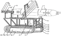
FIG. 1 is a schematic structural diagram of an underwater robot deployment device according to the present invention;
FIG. 2 is a schematic structural diagram of the underwater robot deployment device of the present invention when carrying a robot;
FIG. 3 is a schematic structural view of an underwater robot deployment device in the present invention when the robot is clamped;
fig. 4 is a schematic structural view of the underwater robot deployment device of the present invention when the robot is driven away.
Wherein: the robot comprises a robot 1, a stern part guide frame 11, a main body frame 2, a bottom plate 21, an extension support rod 22, a moving mechanism 3, a chassis cross beam 31, a moving rack 32, a driving wheel 33, a driven wheel 34, a rubber crawler 35, a driving motor 36, a control cabin 4, a hydraulic system 5, a hydraulic actuator 51, a hydraulic output shaft 52, a guide clamp 6, an arc-shaped wheel plate 61, a directional pulley 62, a forward-inclined support 71, a rotary connecting piece 72, a transmission connecting piece 73, an overturning support 81, a push-pull frame rod 82, an overturning connecting piece 83, a U-shaped sliding rail 91, a tail support 92, a U-shaped connecting piece 93 and a hollow plate 94.
Detailed Description
The underwater robot deployment device of the present invention will be described in greater detail in connection with the schematic drawings in which preferred embodiments of the present invention are shown, it being understood that those skilled in the art may modify the invention described herein while still achieving the advantageous effects of the invention. Accordingly, the following description should be construed as broadly as possible to those skilled in the art and not as limiting the invention.
In the description of the present invention, it should be noted that, for the terms of orientation, such as "central", "lateral", "longitudinal", "length", "width", "thickness", "upper", "lower", "front", "rear", "left", "right", "vertical", "horizontal", "top", "bottom", "inner", "outer", "clockwise", "counterclockwise", etc., indicate orientations and positional relationships based on the orientations or positional relationships shown in the drawings, which are merely for convenience of description and simplification of the description, and do not indicate or imply that the device or element referred to must have a specific orientation, be constructed and operated in a specific orientation, and should not be construed as limiting the specific scope of the present invention.
In the present invention, unless otherwise explicitly defined or limited, the terms "assembled", "connected" and "connected" should be construed broadly and include, for example, fixed connections, detachable connections or integral connections; or may be a mechanical connection; the two elements can be directly connected or connected through an intermediate medium, and the two elements can be communicated with each other. The specific meanings of the above terms in the present invention can be understood by those of ordinary skill in the art according to specific situations.
The invention is described in more detail in the following paragraphs by way of example with reference to the accompanying drawings. The advantages and features of the present invention will become more apparent from the following description. It is to be noted that the drawings are in a very simplified form and are not to precise scale, which is merely for the purpose of facilitating and distinctly claiming the embodiments of the present invention.
As shown in fig. 2 to 4, the invention provides an underwater robot deployment device, which comprises a robot 1, a main body frame 2, a moving mechanism 3, a control cabin 4, an energy power system and a hydraulic system 5, wherein:
the robot 1 is used for completing underwater work, and the robot 1 is a torpedo-shaped robot;
the main body frame 2 is used for bearing and clamping the robot 1 and providing an installation position and a space for other structures;
a moving mechanism 3 which carries the main body frame 2 and moves to a specified position;
the control cabin 4 is used for controlling the movement and the function of the whole distribution device;
the energy power system is used for providing power for the operation of the whole distribution device;
and the hydraulic system 5 is used for controlling the head bracket and the jacking bracket to perform laying operation.
Specifically, as shown in fig. 1 to 2, a head bracket, a top pressing bracket and a tail bracket are sequentially arranged on the main body frame 2 from head to tail; the head bracket is supported and supported at the bottom side of the head end of the robot 1; the top pressing frame presses against the top side of the robot 1; the tail bracket is erected on two sides of the tail end of the robot 1, and stern guide frames 11 clamped on the tail bracket are arranged on two sides of the tail end of the robot 1.
Specifically, as shown in fig. 1 to 2, the moving mechanism 3 includes a chassis cross member 31 and crawler-type moving wheels, and the moving mechanism 3 is disposed at the bottom end of the main body frame 2; a plurality of chassis crossbeams 31 are horizontally erected at the bottom of the main body frame 2, namely the chassis crossbeams 31 are fixedly connected with the main body frame 2 through screws, and crawler-type moving wheels are symmetrically arranged at two ends of the chassis crossbeams 31.
Wherein, the crawler-type removes the wheel including removing frame 32, action wheel 33, follow driving wheel 34 and rubber track 35, and the rubber track 35 outside is equipped with the anti-skidding muscle to improve the adhesion nature of track and ground, rubber track 35 inboard is equipped with the induction tooth, is used for normalizing rubber track 35, and action wheel 33 and follow driving wheel 34 are all installed on removing frame 32, action wheel 33 and the meshing of induction tooth, follow driving wheel 34 and be used for supporting rubber track 35.
The energy power system comprises a driving motor, the control cabin 4 is electrically connected with a driving motor 36, the driving motor controls the driving wheel 32 to operate, and the matched driven wheel 33 drives the crawler 34 to operate.
Further, as shown in fig. 1 to 2, a bottom plate 21 fixed on the chassis beam 31 is arranged at the bottom of the main body frame 2, the control cabin 4 is fixedly arranged on the main body frame 2, the hydraulic system 5 is fixedly arranged on the bottom plate 21, and the control cabin 4 is in control connection with the hydraulic system 5. Meanwhile, the head bracket and the jacking frame comprise the hydraulic actuator 51, the transmission mechanism and the guide fixture 6, the hydraulic system 5 is in driving connection with the hydraulic actuator 51, and the position of the guide fixture 6 is controlled by controlling the extension and retraction of the hydraulic output shaft 52 and overturning of the transmission mechanism so as to clamp and fasten or loosen the support and guide the robot 1.
Specifically, as shown in fig. 1 to 2, the head carriage includes a hydraulic actuator 51, a transmission mechanism and a guide jig 6, and a bottom end of the hydraulic actuator 51 is movably connected to the bottom plate 21 at the bottom of the main body frame 2, and a hydraulic output shaft 52 of the hydraulic actuator 51 is connected to the guide jig 6 through the transmission mechanism. The transmission mechanism of the head bracket comprises a forward-leaning bracket 71, a rotary connecting piece 72 and a transmission connecting piece 73, wherein the forward-leaning bracket 71 is of an L-shaped bending structure, and the rotary connecting piece 72 is locked and fixed at the center of a cross beam at the front end of the main body frame 2. One end of the forward-leaning bracket 71 is fixed at the bottom side of the guide clamp 6, the other end is movably connected with the hydraulic output shaft 52 through a transmission connecting piece 73, and the bent part of the forward-leaning bracket 71 is movably connected with the main body frame 2 through a rotating connecting piece 72.
As shown in fig. 4, when the hydraulic output shaft 52 of the hydraulic actuator 51 at the head bracket extends and outputs, the forward-tilting bracket 71 is pushed to rotate forward around the rotary connecting piece 72, so that the forward-tilting bracket 71 drives the guide clamp 6 to move forward at a vertical position, so as to adjust the position of the head end of the robot 1, and facilitate the robot 1 to pull out and drive away.
As shown in fig. 3, when the hydraulic output shaft 52 of the hydraulic actuator 51 at the head bracket is retracted and input, the retracting forward-tilting bracket 71 rotates backward around the rotating connector 72, so that the forward-tilting bracket 71 drives the guide clamp 6 to prop up backward at the forward-tilting position, thereby adjusting the position of the head end of the robot 1 and facilitating the clamping and fastening of the robot 1.
Specifically, as shown in fig. 1 to 2, the top press frame comprises a hydraulic actuator 51, a transmission mechanism and a guide clamp 6, wherein the bottom end of the hydraulic actuator 51 is movably connected with the extension stay 22 outside the main body frame 2, and the hydraulic output shaft 52 of the hydraulic actuator 51 is connected with the guide clamp 6 through the transmission mechanism. The transmission mechanism of the top pressing frame comprises a turning support 81, a push-pull frame rod 82 and a turning connecting piece 83, a horizontal extending support rod 22 is arranged on the outer side of the main body frame 2, and the turning connecting piece 83 is locked and fixed at the middle section of the longitudinal beam at the side end of the main body frame 2. The turning support 81 is of a barb structure, the hooked end of the turning support 81 is fixed on the top side of the guiding fixture 6, the rod-shaped other end of the turning support is movably connected with the main body frame 2 through a turning connecting piece 83, the bottom end of the hydraulic actuator 51 is movably connected with the inner side end of the extending support rod 22, the hydraulic output shaft 52 is respectively connected with two push-pull support rods 82, one push-pull support rod 82 is movably connected with the outer side end of the extending support rod 22, the other push-pull support rod 82 is movably connected with the middle section of the turning support 81, and the extending support rod 22, the hydraulic actuator 51, the turning support 81 and the push-pull support rods 82 are on the same plane.
As shown in fig. 4, when the hydraulic output shaft 52 of the hydraulic actuator 51 at the top pressure frame extends and outputs, the push-pull frame rod 82 is pushed to the outer side of the extension stay bar 22, the turning bracket 81 rotates outwards around the turning connecting piece 83 along with the pulling of the push-pull frame rod 82, so that the turning bracket 81 drives the guide fixture 6 to move outwards in a loose manner, the guide fixture 6 is far away from the top side of the robot 1 to loosen the clamping action on the top side of the robot 1, and the robot 1 can conveniently pull out and drive away.
As shown in fig. 3, when the hydraulic output shaft 52 of the hydraulic actuator 51 at the top pressure frame contracts and inputs, the push-pull frame rod 82 is pulled towards the inner side of the extension stay 22, the turning support 81 rotates inwards around the turning connecting piece 83 along with the pushing force of the push-pull frame rod 82, so that the turning support 81 drives the guide fixture 6 to move towards the inner side, and the guide fixture 6 presses the top side of the robot 1 to clamp the clamping action on the top side of the robot 1, thereby facilitating the clamping and fastening of the robot 1.
Furthermore, the end of the hydraulic output shaft 52 is in a flat circular ring shape, the push-pull rack rod 82 is in an H shape, and the end of the hydraulic output shaft 52 is matched with the push-pull rack rod 82 and movably connected through a bolt.
Further, the guiding fixture 6 comprises an arc-shaped wheel plate 61 and directional pulleys 62 symmetrically arranged on two inner sides of the arc-shaped wheel plate 61, and the directional pulleys 62 are fixed on short rib plates extending obliquely from the arc-shaped wheel plate 61 through screws, so that the two directional pulleys 62 are inclined inwards relatively, the wheel surfaces of the directional pulleys 62 are ensured to be in close contact with the robot 1, and the robot 1 can slide through the directional pulleys 62 conveniently.
Meanwhile, as shown in fig. 1 to 2, the tail bracket includes a U-shaped slide rail 91 and an L-shaped tail bracket support frame 92, the U-shaped slide rail 91 is fixed on the plurality of parallel tail bracket support frames 92, and the opening direction of the U-shaped slide rail 91 is the same as the moving direction of the robot 1, the stern guide frame 11 is clamped and arranged on the inner side of the U-shaped slide rail 91, and plays a role of guiding while supporting the torpedo robot 1.
Specifically, as shown in fig. 1 to fig. 2, a U-shaped connector 93 is disposed at a bent portion of the U-shaped slide rail 91 for connecting the U-shaped slide rail 91 in a U-shape, that is, the U-shaped slide rail 91 is formed by two slide bars fastened and connected in a U-shape through the U-shaped connector 93. One side of the U-shaped connecting member 93 is provided with a hollow plate member 94 for reinforcing the U-shaped slide rail 91 in a U-shape. The hollow plate 94 is fastened and connected with the two sliding rods through a hollow position in the middle by screws, so that the firmness of the U-shaped sliding rail 91 is enhanced.
The specific working principle is as follows:
as shown in fig. 3 to 4, when the crawler-type moving wheel drives the robot 1 to travel to a designated position, the torpedo-shaped underwater robot 1 gradually drives away from the deploying device, the stern portion guide frames 11 on both sides of the stern portion slide along the U-shaped slide rails 91 on both sides of the main body frame 2, meanwhile, the hydraulic system 5 controls the two hydraulic actuators 51 to work simultaneously, so that the hydraulic actuators push out the hydraulic output shafts 52, the transmission mechanism of the jacking frame is pushed by the hydraulic actuators 51 to turn over and loose to the outside, and the jacking frame is in an open state at this time; the transmission mechanism of the head carriage is forwardly displaced by the urging of the hydraulic actuator 51. The main body of the torpedo robot 1 will gradually slide forward along the directional pulleys 62 of the upper and lower two guiding jigs 6 until it moves away from the laying device.
In summary, in this embodiment, the proposed underwater robot deployment device has the following advantages:
1. the crawler-type moving mechanism has the characteristics of large moving range, good maneuvering performance, rapidness and safety;
2. the overall structure of the distributing device fully utilizes each space position of the main body frame, reduces the load, prolongs the working time, and is suitable for various underwater long-distance long-time working occasions;
3. the pulley that adopts in the structure of pressing card top support combines with the mode of slide rail, can play a fixed and supported effect to torpedo robot, can play a guide effect again.
The above description is only a preferred embodiment of the present invention, and does not limit the present invention in any way. It will be understood by those skilled in the art that various changes, substitutions and alterations can be made herein without departing from the spirit and scope of the invention as defined by the appended claims.
Claims (10)
1. The underwater robot laying device is characterized by comprising a robot (1), a main body frame (2), a moving mechanism (3), a control cabin (4) and an energy power system, wherein:
the robot (1) is used for completing underwater work;
the main body frame (2) is used for bearing and clamping the robot (1) and providing an installation position and a space; a head bracket, a jacking bracket and a tail bracket are sequentially arranged on the main body frame (2) from head to tail; the head bracket is supported and propped against the bottom side of the head end of the robot (1); the top pressing frame presses against the top side of the robot (1); the tail bracket is erected on two sides of the tail end of the robot (1), and stern guide frames (11) clamped on the tail bracket are arranged on two sides of the tail end of the robot (1);
the moving mechanism (3) bears the main body frame (2) and moves to a specified position; the moving mechanism (3) is arranged at the bottom end of the main body frame (2);
the control cabin (4) is used for controlling the movement and the function of the whole distribution device;
the energy power system is used for providing power for the operation of the whole distribution device.
2. The underwater robot deployment device of claim 1, wherein the moving mechanism (3) comprises a chassis beam (31) and crawler-type moving wheels, the chassis beam (31) is horizontally erected at the bottom of the main body frame (2), and the crawler-type moving wheels are symmetrically arranged at two ends of the chassis beam (31);
the crawler-type moving wheel comprises a moving frame (32), an driving wheel (33), a driven wheel (34) and a rubber crawler (35), anti-skid ribs are arranged on the outer side of the rubber crawler (35), inducing teeth are arranged on the inner side of the rubber crawler (35), the driving wheel (33) and the driven wheel (34) are installed on the moving frame (32), the driving wheel (33) is meshed with the inducing teeth, and the driven wheel (34) is used for supporting the rubber crawler (35).
3. The underwater robot deployment device of claim 1, further comprising a hydraulic system (5) for controlling the head bracket and the top press frame to perform deployment operations;
the head bracket and the top pressing frame both comprise a hydraulic actuator (51), a transmission mechanism and a guide clamp (6), the bottom end of the hydraulic actuator (51) is movably connected with the main body frame (2), a hydraulic output shaft (52) of the hydraulic actuator (51) is connected with the guide clamp (6) through the transmission mechanism, and the hydraulic system (5) is in driving connection with the hydraulic actuator (51);
the control cabin (4) and the hydraulic system (5) are both fixedly arranged on the inner side of the main body frame (2), and the control cabin (4) is in control connection with the hydraulic system (5).
4. The underwater robot deployment device according to claim 3, wherein the guiding jig (6) includes an arc-shaped wheel plate (61) and directional pulleys (62) symmetrically disposed on both inner sides of the arc-shaped wheel plate (61).
5. The underwater robot deployment device according to claim 3, wherein the transmission mechanism of the head bracket comprises a forward-tilting bracket (71), a rotary connector (72) and a transmission connector (73), the forward-tilting bracket (71) is of a bent structure, one end of the forward-tilting bracket (71) is connected with the guide clamp (6), the other end of the forward-tilting bracket is movably connected with the hydraulic output shaft (52) through the transmission connector (73), the bent part of the forward-tilting bracket (71) is movably connected with the main frame (2) through the rotary connector (72), and the bottom end of the hydraulic actuator (51) is movably connected with the main frame (2).
6. Underwater robot deployment device according to claim 5, characterised in that a bottom plate (21) is provided at the bottom of the main body frame (2), the control pod (4) is fixedly arranged on the main body frame (2), the hydraulic system (5) is fixedly arranged on the bottom plate (21), and the bottom end of the hydraulic actuator (51) in the head bracket is movably connected with the bottom plate (21).
7. The underwater robot deployment device according to claim 3, wherein the transmission mechanism of the jacking frame comprises a turning support (81), push-pull frame rods (82) and a turning connecting piece (83), the turning support (81) is of a barb structure, one hooked end of the turning support (81) is connected with the guide fixture (6), the other rod-shaped end of the turning support is movably connected with the main body frame (2) through the turning connecting piece (83), the bottom end of the hydraulic actuator (51) is movably connected with the main body frame (2), the hydraulic output shaft (52) is respectively connected with the two push-pull frame rods (82), one push-pull frame rod (82) is rotatably fixed on the main body frame (2), and the other push-pull frame rod (82) is rotatably fixed at the middle section of the turning support (81).
8. The underwater robot deployment device according to claim 7, wherein the outside of the main body frame (2) is provided with an extension stay (22), and the bottom ends of the hydraulic actuators (51) in one of the push-pull frame rod (82) and the top press frame are movably connected with the bottom plate (21).
9. The underwater robot deployment device according to claim 1, wherein the tail bracket comprises a U-shaped slide rail (91) and a tail bracket support frame (92), the U-shaped slide rail (91) is fixed on the plurality of parallel tail bracket support frames (92), the opening direction of the U-shaped slide rail (91) is consistent with the moving direction of the robot (1), and the stern guide frame (11) is clamped and arranged on the inner side of the U-shaped slide rail (91).
10. The underwater robot arrangement device of claim 9, wherein a U-shaped connecting member (93) is disposed at a bent portion of the U-shaped slide rail (91) for connecting the U-shaped slide rail (91) in a U-shape, and a hollow plate member (94) is disposed at one side of the U-shaped connecting member (93) for reinforcing the U-shaped slide rail (91) in a U-shape.
Priority Applications (1)
| Application Number | Priority Date | Filing Date | Title |
|---|---|---|---|
| CN202211395731.1A CN115675673A (en) | 2022-11-08 | 2022-11-08 | Underwater robot laying device |
Applications Claiming Priority (1)
| Application Number | Priority Date | Filing Date | Title |
|---|---|---|---|
| CN202211395731.1A CN115675673A (en) | 2022-11-08 | 2022-11-08 | Underwater robot laying device |
Publications (1)
| Publication Number | Publication Date |
|---|---|
| CN115675673A true CN115675673A (en) | 2023-02-03 |
Family
ID=85049355
Family Applications (1)
| Application Number | Title | Priority Date | Filing Date |
|---|---|---|---|
| CN202211395731.1A Pending CN115675673A (en) | 2022-11-08 | 2022-11-08 | Underwater robot laying device |
Country Status (1)
| Country | Link |
|---|---|
| CN (1) | CN115675673A (en) |
-
2022
- 2022-11-08 CN CN202211395731.1A patent/CN115675673A/en active Pending
Similar Documents
| Publication | Publication Date | Title |
|---|---|---|
| EP3250345B1 (en) | Underwater manipulator arm robot | |
| US8051793B2 (en) | Retractable hydrofoil for marine vehicles | |
| US7815394B2 (en) | Device for a watercraft for picking up and launching boats | |
| US7520239B2 (en) | Retractable leg assembly for amphibious vehicle | |
| CN104002929B (en) | A kind of folding and unfolding method of canoe | |
| CN218662125U (en) | Underwater robot laying device | |
| CN115675673A (en) | Underwater robot laying device | |
| RU2700240C1 (en) | All-purpose vehicle on rotary screw propulsor | |
| WO2009048342A9 (en) | Mooring system and related means | |
| CN104044700B (en) | A kind of draw off gear of canoe | |
| US20130017019A1 (en) | Laying Ramp, Laying Unit Comprising Such a Laying Ramp, and Method of Operating Such a Laying Unit | |
| CN204037852U (en) | A kind of draw off gear of canoe | |
| CN210347091U (en) | Automobile towing hook strength test detection device | |
| CN111319735B (en) | Three-stage folding and unfolding mechanism for boat | |
| CN113401323A (en) | Modular slideway clamping type recovery device for autonomously recovering underwater robot | |
| CN111139811B (en) | Ship lift chamber bottom obstacle cleaning device and method | |
| CN116373514A (en) | Caterpillar ROV with dual-mode operation capability | |
| CN110094166B (en) | Joint-cutting hole drilling machine | |
| US20060000121A1 (en) | Excavation apparatus and method | |
| CN115026556B (en) | Multifunctional climbing operation platform and operation method | |
| US9975620B2 (en) | Bow and stern thruster and related methods | |
| CN115384601B (en) | Sail navigation-aiding snowfield roaming robot and method | |
| CN204037853U (en) | A kind of draw off gear of canoe | |
| CN117141685A (en) | Underwater dynamic recovery device for underwater robot | |
| CN115723905B (en) | Towing type retraction device |
Legal Events
| Date | Code | Title | Description |
|---|---|---|---|
| PB01 | Publication | ||
| PB01 | Publication | ||
| SE01 | Entry into force of request for substantive examination | ||
| SE01 | Entry into force of request for substantive examination | ||
| CB03 | Change of inventor or designer information |
Inventor after: Zhang Cheng Inventor after: Gan Wenyang Inventor after: Chu Zhenzhong Inventor after: Xia Tianxing Inventor after: Yu Xing Inventor before: Zhang Cheng Inventor before: Gan Wenyang Inventor before: Chu Zhenzhong Inventor before: Xia Tianxing Inventor before: Yu Xing |
|
| CB03 | Change of inventor or designer information |