CN115672848A - Cleaning equipment for building floor and using method thereof - Google Patents
Cleaning equipment for building floor and using method thereof Download PDFInfo
- Publication number
- CN115672848A CN115672848A CN202211702033.1A CN202211702033A CN115672848A CN 115672848 A CN115672848 A CN 115672848A CN 202211702033 A CN202211702033 A CN 202211702033A CN 115672848 A CN115672848 A CN 115672848A
- Authority
- CN
- China
- Prior art keywords
- cleaning
- air inlet
- cooling tower
- building floor
- lifting frame
- Prior art date
- Legal status (The legal status is an assumption and is not a legal conclusion. Google has not performed a legal analysis and makes no representation as to the accuracy of the status listed.)
- Granted
Links
Images


Abstract
The invention belongs to the technical field of cleaning equipment, and particularly relates to cleaning equipment for a building floor and a using method thereof, wherein the cleaning equipment for the building floor comprises the following components: the feeding and conveying mechanism conveys the building floor slab to the cleaning mechanism, and the cleaning mechanism drives the building floor slab to be immersed into a cleaning solution in the cleaning tank for cleaning; the cleaning mechanism drives the building floor to be separated from the cleaning pool and incline towards the discharging and conveying mechanism; the cooling tower mechanism exchanges heat with the cleaning solution in the cleaning pool through the heat exchange mechanism; the intelligent feeding, cleaning and discharging device can realize intelligent feeding, cleaning and discharging, and meanwhile, through the cooperation of the cooling tower mechanism and the heat exchange mechanism, the temperature of the cleaning solution in the cleaning pool can be controlled, the cleaning effect is ensured, the volatilized cleaning solution can be diluted, and the cleaning safety is improved.
Description
Technical Field
The invention belongs to the technical field of cleaning equipment, and particularly relates to cleaning equipment for a building floor slab and a using method of the cleaning equipment.
Background
The surface of the building floor still has residual cement after demoulding, so the cement on the building floor needs to be cleaned, a cleaning pool needs to be built, the building floor is soaked in the cleaning solution, the hydrochloric acid is contained in the cleaning solution, but the hydrochloric acid has volatility, the concentration is heavy, the corrosivity is high, and the volatile cleaning solution needs to be treated.
Cleaning solution can produce a large amount of heats cleaning building floor, cleaning solution's temperature needs accurate control in certain extent, can not be too high also can not hang down excessively, otherwise can influence the cleaning performance, the tradition adopts the cooling tower to carry out the heat transfer, the coolant liquid that nevertheless returns to the cooling tower need cool down, traditional cooling tower is direct to be windowed in the side, because pack in order to guarantee the cooling performance to cooling tower cooling liquid, it is outer thin interior thick setting to pack, the cooling tower is direct to be windowed in the side and can cause cooling tower interior air volume from outer to inner decay, can influence the life of packing, the invariable air volume makes cooling tower cooling liquid low in winter environment simultaneously, and then influence cleaning solution's temperature.
Therefore, there is a need to develop a new cleaning device for building floor and a method for using the same to solve the above problems.
Disclosure of Invention
The invention aims to provide cleaning equipment for a building floor and a using method thereof.
In order to solve the above technical problems, the present invention provides a cleaning apparatus for a building floor, comprising: the device comprises a cooling tower mechanism, a feeding conveying mechanism, a cleaning pool, a heat exchange mechanism, a cleaning mechanism and a discharging conveying mechanism; the feeding conveying mechanism is positioned on the feeding side of the cleaning pool, the discharging conveying mechanism is positioned on the discharging side of the cleaning pool, the heat exchange mechanism is positioned in the cleaning pool and communicated with the cooling tower mechanism, and the cleaning mechanism is movably arranged above the cleaning pool; the feeding and conveying mechanism conveys the building floor to the cleaning mechanism, and the cleaning mechanism drives the building floor to be immersed into a cleaning solution in the cleaning pool for cleaning; the cleaning mechanism drives the building floor slab to be separated from the cleaning pool and incline towards the discharging and conveying mechanism, so that the building floor slab slides from the cleaning mechanism to the discharging and conveying mechanism; and the cooling tower mechanism exchanges heat with the cleaning solution in the cleaning pool through the heat exchange mechanism.
Further, the heat exchange mechanism includes: a heat exchange conduit; the heat exchange pipeline is arranged in the cleaning tank and is communicated with the cooling tower mechanism; and the cooling tower mechanism circulates cooling liquid through a heat exchange pipeline so as to exchange heat with the cleaning solution in the cleaning pool, namely, the cleaning pool is heated, or the temperature is preserved or reduced.
Further, the cleaning mechanism includes: the lifting device comprises a first lifting cylinder, a first lifting frame, a second lifting cylinder and a second lifting frame; the movable part of the first lifting cylinder is connected with a first lifting frame, and the movable part of the second lifting cylinder is connected with a second lifting frame; the first lifting frame is movably arranged above the feeding position of the cleaning pool, and the second lifting frame is movably arranged above the discharging position of the cleaning pool; the first lifting cylinder drives the first lifting frame, the second lifting cylinder drives the second lifting frame to move to the position below the feeding conveying belt, so that the first lifting frame and the second lifting frame receive the building floor slab sent out by the feeding conveying mechanism, and the first lifting cylinder drives the first lifting frame and the second lifting cylinder drives the second lifting frame to drive the building floor slab to be immersed into a cleaning solution in the cleaning pool for cleaning; first lift cylinder drive first crane, second lift cylinder drive second crane drive building floor and break away from the washing pond, just first lift cylinder drive first crane is higher than the second crane to make building floor orientation ejection of compact conveying mechanism inclines.
Further, the outfeed conveyor mechanism comprises: a discharging conveyer belt; the discharging conveying belt is positioned on the discharging side of the cleaning tank; the discharging conveyer belt receives the building floor slab sliding off from the cleaning mechanism so as to convey the building floor slab to a discharging area.
Further, the cooling tower mechanism includes: at least one cooling tower; the cooling tower body circulates cooling liquid through the heat exchange mechanism.
Further, each side surface on the cooling tower body is provided with an air inlet window; an air inlet box and an air inlet grille are movably arranged at the air inlet window, and the air inlet grille is movably arranged above the air inlet box; the air inlet box is positioned below the filler in the cooling tower body, the bottom of the air inlet box is provided with an air inlet, one side of the air inlet box, which faces the interior of the cooling tower body, is provided with an air outlet, and the top of the air inlet box is arranged in a stepped inclined plane; when the suction fan at the top of the cooling tower body sucks air, air enters the air inlet on the air inlet box and the air inlet grille, and air flow absorbs heat in cooling liquid in the cooling tower body through the filler and is discharged from the suction fan, namely the air inlet box is pushed to stretch into the cooling tower body or stretch out of the cooling tower body, so that the air inlet amount of the air inlet, the air inlet amount of the air inlet grille and the position of the air outlet below the filler are adjusted; the relative air inlet grid of air inlet case removes in order to vibrate the air inlet grid, so that impurity landing to the top of air inlet case on the air inlet grid, just the condensation water drips to the top of air inlet case in the cooling tower body in order to clear away impurity.
Furthermore, a wind shield is arranged at the top of the air inlet box, and the wind shield is arranged in parallel to the air inlet grille and is positioned in the cooling tower body; pushing the air inlet box to extend out of the cooling tower body until the air inlet grille is blocked by the wind blocking plate, so that all air enters the filler from the bottom of the filler through the air inlet; the air baffle, the top of the cooling tower body and the air inlet grille form a thermostatic bath to collect the dropped condensed water and keep the temperature constant until the condensed water overflows from the thermostatic bath to wash the top of the air inlet tank.
Further, a first cover body is arranged at the top of the first lifting frame, and a second cover body is arranged at the top of the second lifting frame; the side surface of the air inlet box is provided with a pipe joint communicated with the air duct, and the first cover body and the second cover body are connected with the pipe joint through corresponding pipelines; and the volatilized white fog generated by the cleaning solution in the cleaning pool enters the air channel through the first cover body and the second cover body to be diluted by the dropped condensed water.
In another aspect, the present invention provides a method for using the above cleaning apparatus for building floor, including: the feeding and conveying mechanism conveys the building floor slab to the cleaning mechanism, and the cleaning mechanism drives the building floor slab to be immersed into a cleaning solution in the cleaning tank for cleaning; the cleaning mechanism drives the building floor slab to be separated from the cleaning pool and incline towards the discharge conveying mechanism, so that the building floor slab slides from the cleaning mechanism to the discharge conveying mechanism; and the cooling tower mechanism exchanges heat with the cleaning solution in the cleaning pool through the heat exchange mechanism.
The intelligent feeding, cleaning and discharging device has the advantages that intelligent feeding, cleaning and discharging can be achieved, meanwhile, through the cooperation of the cooling tower mechanism and the heat exchange mechanism, the temperature of the cleaning solution in the cleaning pool can be controlled, the cleaning effect is guaranteed, the volatilized cleaning solution can be diluted, and the cleaning safety is improved.
Additional features and advantages of the invention will be set forth in the description which follows, and in part will be obvious from the description, or may be learned by practice of the invention.
In order to make the aforementioned and other objects, features and advantages of the present invention comprehensible, preferred embodiments accompanied with figures are described in detail below.
Drawings
In order to more clearly illustrate the embodiments of the present invention or the technical solutions in the prior art, the drawings used in the description of the embodiments or the prior art will be briefly described below, and it is obvious that the drawings in the following description are some embodiments of the present invention, and other drawings can be obtained by those skilled in the art without creative efforts.
FIG. 1 is a view showing the construction of a cleaning apparatus for a construction floor according to the present invention;
FIG. 2 is a block diagram of the feed delivery mechanism of the present invention;
FIG. 3 is a block diagram of the cleaning tank of the present invention;
FIG. 4 is a block diagram of the wash mechanism of the present invention;
FIG. 5 is a block diagram of the outfeed conveyor mechanism of the present invention;
FIG. 6 is a block diagram of a cooling tower mechanism of the present invention;
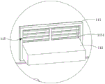
FIG. 7 is a partial block diagram of the cooling tower of the present invention;
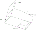
fig. 8 is a structural view of an air inlet box of the present invention.
In the figure:
1. a cooling tower mechanism; 11. cooling the tower body; 111. an air inlet window; 112. an air inlet box; 1121. an air inlet; 1122. an air outlet; 1123. a step slope; 1124. a wind deflector; 1125. a pipe interface; 113. an air inlet grille; 1131. a grid leaf; 12. an exhaust fan;
2. a feed conveying mechanism; 21. a feed conveyor belt;
3. a cleaning tank;
4. a heat exchange mechanism; 41. a heat exchange conduit;
5. a cleaning mechanism; 51. a first lifting frame; 52. a second lifting frame; 53. a first cover body; 54. a second cover body;
6. a discharge conveying mechanism; 61. and (7) a discharging conveyer belt.
Detailed Description
To make the objects, technical solutions and advantages of the embodiments of the present invention clearer, the technical solutions of the present invention will be clearly and completely described below with reference to the accompanying drawings, and it is apparent that the described embodiments are some, but not all embodiments of the present invention. All other embodiments, which can be derived by a person skilled in the art from the embodiments given herein without making any creative effort, shall fall within the protection scope of the present invention.
Example 1
In this embodiment, as shown in fig. 1 to 8, the present embodiment provides a cleaning apparatus for a building floor, including: the device comprises a cooling tower mechanism 1, a feeding conveying mechanism 2, a cleaning pool 3, a heat exchange mechanism 4, a cleaning mechanism 5 and a discharging conveying mechanism 6; the feeding conveying mechanism 2 is positioned on the feeding side of the cleaning pool 3, the discharging conveying mechanism 6 is positioned on the discharging side of the cleaning pool 3, the heat exchange mechanism 4 is positioned in the cleaning pool 3 and communicated with the cooling tower mechanism 1, and the cleaning mechanism 5 is movably arranged above the cleaning pool 3; the feeding and conveying mechanism 2 conveys the building floor slab to a cleaning mechanism 5, and the cleaning mechanism 5 drives the building floor slab to be immersed into a cleaning solution in a cleaning pool 3 for cleaning; the cleaning mechanism 5 drives the building floor slab to be separated from the cleaning pool 3 and incline towards the discharging and conveying mechanism 6, so that the building floor slab slides from the cleaning mechanism 5 to the discharging and conveying mechanism 6; and the cooling tower mechanism 1 exchanges heat with the cleaning solution in the cleaning pool 3 through the heat exchange mechanism 4.
In this embodiment, intelligent feeding, washing and the ejection of compact can be realized to this embodiment, simultaneously through cooling tower mechanism 1 and the 4 cooperation of heat transfer mechanism, can guarantee the cleaning performance to cleaning solution accuse temperature in the washing pond 3, and can dilute volatile cleaning solution, improve abluent security.
Because the concrete sediment appears on building floor uses the back surface and glues and influence the secondary use last, the workman can only be single at every turn beat, means clearance such as strike and manual polishing, the operation can be operated the deformation and influence the precision of secondary use and the unclean condition of clearance, the efficiency of clearance extremely low influence production efficiency in addition.
In this embodiment, the infeed conveyor 21 serves to feed the building floor into the washer mechanism 5.
In this embodiment, the heat exchanging mechanism 4 includes: a heat exchange conduit 41; the heat exchange pipeline 41 is arranged in the cleaning pool 3 and is communicated with the cooling tower mechanism 1; the cooling tower mechanism 1 circulates cooling liquid through a heat exchange pipeline 41 to exchange heat with the cleaning solution in the cleaning pool 3, namely, the cleaning pool 3 is heated or kept warm or cooled.
In this embodiment, since the cleaning solution can generate heat when cleaning the building floor, the cooling liquid in the heat exchange pipeline 41 can take away the heat from the cleaning tank 3 in a circulating manner, so as to achieve a good heat exchange effect.
In the present embodiment, the cleaning mechanism 5 includes: a first lifting cylinder, a first lifting frame 51, a second lifting cylinder and a second lifting frame 52; the movable part of the first lifting cylinder is connected with a first lifting frame 51, and the movable part of the second lifting cylinder is connected with a second lifting frame 52; the first lifting frame 51 is movably arranged above the feeding position of the cleaning pool 3, and the second lifting frame 52 is movably arranged above the discharging position of the cleaning pool 3; the first lifting cylinder drives the first lifting frame 51, the second lifting cylinder drives the second lifting frame 52 to move to the lower part of the feeding conveyer belt 21, so that the first lifting frame 51 and the second lifting frame 52 receive the building floor slab sent out by the feeding conveyer mechanism 2, and the first lifting cylinder drives the first lifting frame 51 and the second lifting frame 52 to drive the building floor slab to be immersed into the cleaning solution in the cleaning pool 3 for cleaning; the first lifting cylinder drives the first lifting frame 51, the second lifting cylinder drives the second lifting frame 52 to drive the building floor slab to be separated from the cleaning pool 3, and the first lifting cylinder drives the first lifting frame 51 to be higher than the second lifting frame 52 so that the building floor slab inclines towards the discharging and conveying mechanism 6.
In the present embodiment, the first crane 51 and the second crane 52 are changed in shape, so that the building floor can be received, cleaned, and delivered.
In this embodiment, the outfeed conveyor mechanism 6 comprises: a discharge conveyor belt 61; the discharging conveyer belt 61 is positioned at the discharging side of the cleaning pool 3; the discharge conveyor 61 receives the building floor slid off the cleaning mechanism 5 to deliver the building floor to the discharge area.
In the present embodiment, the discharge conveyor 61 functions to discharge the building floor to the discharge area.
In the present embodiment, the cooling tower apparatus 1 includes: at least one cooling tower 11; the cooling tower body 11 circulates cooling liquid through the heat exchange mechanism 4.
In this embodiment, each side surface of the cooling tower body 11 is provided with an air inlet window 111; an air inlet box 112 and an air inlet grille 113 are movably arranged at the air inlet window 111, and the air inlet grille 113 is movably arranged above the air inlet box 112; the air inlet box 112 is located below the filler inside the cooling tower body 11, an air inlet 1121 is formed in the bottom of the air inlet box 112, an air outlet 1122 is formed in one side, facing the inside of the cooling tower body 11, of the air inlet box 112, and the top of the air inlet box 112 is arranged in a stepped inclined plane 1123; when the suction fan 12 at the top of the cooling tower 11 sucks air, air enters the air inlet 1121 and the air inlet grille 113 on the air inlet box 112, and the air flow passes through the filler to absorb heat in the cooling liquid in the cooling tower 11 and is discharged from the suction fan 12, that is, the air inlet box 112 is pushed to extend into the cooling tower 11 or extend out from the cooling tower 11, so as to adjust the air inlet amount of the air inlet 1121, the air inlet amount of the air inlet grille 113 and the position of the air outlet 1122 below the filler; the air inlet box 112 moves relative to the air inlet grille 113 to vibrate the air inlet grille 113, so that impurities on the air inlet grille 113 slide to the top of the air inlet box 112, and condensed water in the cooling tower body 11 drops to the top of the air inlet box 112 to remove the impurities.
The cooling liquid is heated through the heat exchange pipe, and the cooling liquid returned to the cooling tower unit needs to be cooled, the conventional cooling tower body 11 is directly windowed on the side surface, because the filler is arranged with a thin outer layer and a thick inner layer to ensure the cooling effect on the cooling liquid in the cooling tower body 11, the air quantity in the cooling tower body 11 is attenuated from outside to inside due to the direct windowing of the side surface of the cooling tower body 11, the service life of the filler is influenced, meanwhile, the air quantity is constant in winter, the cooling liquid in the cooling tower body 11 is too low, the cleaning solution in the cleaning tank 3 is influenced, in the embodiment, an air inlet box 112 and an air inlet grille 113 are movably arranged at the air inlet window 111, because the air inlet box 112 is positioned below the filler in the cooling tower body 11, the air flow pumped into the cooling tower body 11 from an air inlet 1121 directly enters the filler through an air outlet 1122 instead of permeating from the outside of the filler inwards, therefore, the cooling effect of the air flow entering the filler from the air inlet box 112 on the cooling liquid is better, because the filler is arranged with a thin outer part and a thick inner part, the air quantity can be attenuated from the outside to the inside by directly windowing the side surface of the traditional cooling tower body 11, the filler and the air flow form opposite impact, and the cooling tower body is more easily damaged by fatigue, the air quantity entering the cooling tower body 11 is matched with the filler after the air inlet box 112 is arranged, the service life of the filler can be prolonged, meanwhile, the cooling effect on the cooling liquid is better, the top part of the air inlet box 112 is arranged in a step inclined plane 1123, when the air inlet box 112 gradually extends into the cooling tower body 11, the air inlet quantity of the air inlet grille 113 is gradually increased, the air inlet quantity of the air inlet 1121 is gradually reduced, the cooling tower body 11 needs to be insulated when the air inlet box 112 gradually extends out of the cooling tower body 11 in autumn, the air inlet grille 113 is gradually reduced, and the air inlet quantity of the air inlet 1121 is gradually increased, the cooling liquid in the cooling tower body 11 needs to be cooled when the cooling tower is suitable for spring and summer seasons, and meanwhile, the position of the air inlet box 112 can be adjusted according to actual conditions, so that the service life of the filler is prolonged, and the cooling effect is coordinated.
In this embodiment, a wind shield 1124 is disposed on the top of the air inlet box 112, and the wind shield 1124 is disposed in parallel with the air inlet grille 113 and is located in the cooling tower 11; pushing the air inlet box 112 to extend out from the cooling tower 11 until the air baffles 1124 block the air inlet grilles 113, so that all the air enters the filler from the bottom of the filler through the air inlets 1121; the wind screen 1124, the top of the cooling tower 11 and the air inlet grille 113 form a thermostatic bath for collecting the dripping condensate water to keep constant temperature until the condensate water overflows from the thermostatic bath to flush the top of the air inlet box 112.
In this embodiment, when the cooling tower 11 does not work or the environmental adjustment is poor, the wind screen 1124 directly blocks the air inlet grille 113, so as to prevent impurities from entering the cooling tower 11 and prevent the filler from being polluted.
In this embodiment, the air inlet grille 113 includes a spring post and a plurality of grids 1131, each grid 1131 is longitudinally arranged on the spring post at an interval, the top end of the spring post is movably connected to the inside of the air inlet window 111, the other end of the spring post abuts against the step slope 1123, the spring post can be abutted into the air inlet window 111, and the grids 1131 at the lowest end of the spring post, the wind shield 1124 and the top of the cooling tower 11 form a thermostatic bath.
In this embodiment, the condensate water drop can be in the thermostatic bath, splashes at the top of cooling tower body 11 for the heat scatters in thermostatic bath department, forms the thermostatted layer, avoids freezing or forming the ice bank and stopping up air inlet window 111 and freeze the bottom of cooling tower body 11 because the temperature is low excessively in air inlet window 111 in autumn and winter season, and the comdenstion water can wash out the top of air inlet box 112 when overflowing from the thermostatic bath simultaneously, keeps air inlet box 112 clean.
In this embodiment, a first cover 53 is provided on the top of the first crane 51, and a second cover 54 is provided on the top of the second crane 52; the side surface of the air inlet box 112 is provided with a pipe connector 1125 communicated with an air duct, and the first cover body 53 and the second cover body 54 are connected with the pipe connector 1125 through corresponding pipes; the volatilized white fog generated by the cleaning solution in the cleaning pool 3 enters the air duct through the first cover body 53 and the second cover body 54 to be diluted by the dropped condensed water.
In this embodiment, there is suction in the wind channel, can induced draft from first cover body 53, the second cover body 54 to the white fog that volatilizees that cleaning solution produced in will wasing pond 3 takes away, can produce the comdenstion water in the cooling tower body 11 simultaneously, and the comdenstion water drips along the wind channel, thereby dilutes and takes away white vaporific cleaning solution.
Example 2
On the basis of embodiment 1, the present embodiment provides a method for using the cleaning apparatus for building floor provided in embodiment 1, which includes: the feeding and conveying mechanism 2 conveys the building floor slab to the cleaning mechanism 5, and the cleaning mechanism 5 drives the building floor slab to be immersed into the cleaning solution in the cleaning tank 3 for cleaning; the cleaning mechanism 5 drives the building floor slab to be separated from the cleaning pool 3 and incline towards the discharging and conveying mechanism 6, so that the building floor slab slides from the cleaning mechanism 5 to the discharging and conveying mechanism 6; and the cooling tower mechanism 1 exchanges heat with the cleaning solution in the cleaning pool 3 through the heat exchange mechanism 4.
In conclusion, the intelligent feeding, cleaning and discharging device can realize intelligent feeding, cleaning and discharging, meanwhile, the temperature of the cleaning solution in the cleaning pool can be controlled by matching the cooling tower mechanism with the heat exchange mechanism, the cleaning effect is ensured, the volatile cleaning solution can be diluted, and the cleaning safety is improved.
The components (components without specific structures) selected for use in the present application are all common standard components or components known to those skilled in the art, and the structures and principles thereof can be known to those skilled in the art through technical manuals or through routine experimental methods.
In the description of the embodiments of the present invention, unless otherwise explicitly specified or limited, the terms "mounted," "connected," and "connected" are to be construed broadly and may, for example, be fixedly connected, detachably connected, or integrally connected; can be mechanically or electrically connected; they may be connected directly or indirectly through intervening media, or they may be interconnected between two elements. The specific meanings of the above terms in the present invention can be understood in specific cases to those skilled in the art.
In the description of the present invention, it should be noted that the terms "center", "upper", "lower", "left", "right", "vertical", "horizontal", "inner", "outer", etc., indicate orientations or positional relationships based on the orientations or positional relationships shown in the drawings, and are only for convenience of description and simplicity of description, but do not indicate or imply that the device or element being referred to must have a particular orientation, be constructed and operated in a particular orientation, and thus, should not be construed as limiting the present invention. Furthermore, the terms "first," "second," and "third" are used for descriptive purposes only and are not to be construed as indicating or implying relative importance.
In the several embodiments provided in the present application, it should be understood that the disclosed system, apparatus and method may be implemented in other ways. The above-described apparatus embodiments are merely illustrative, and for example, the division of the units into only one type of logical function may be implemented in other ways, and for example, multiple units or components may be combined or integrated into another system, or some features may be omitted, or not implemented. In addition, the shown or discussed mutual coupling or direct coupling or communication connection may be an indirect coupling or communication connection of devices or units through some communication interfaces, and may be in an electrical, mechanical or other form.
The units described as separate parts may or may not be physically separate, and parts displayed as units may or may not be physical units, may be located in one place, or may be distributed on a plurality of network units. Some or all of the units can be selected according to actual needs to achieve the purpose of the solution of the embodiment.
In addition, functional units in the embodiments of the present invention may be integrated into one processing unit, or each unit may exist alone physically, or two or more units are integrated into one unit.
In light of the foregoing description of the preferred embodiment of the present invention, many modifications and variations will be apparent to those skilled in the art without departing from the spirit and scope of the invention. The technical scope of the present invention is not limited to the content of the specification, and must be determined according to the scope of the claims.
Claims (6)
1. A cleaning apparatus for building floor slabs, comprising:
the device comprises a cooling tower mechanism, a feeding conveying mechanism, a cleaning pool, a heat exchange mechanism, a cleaning mechanism and a discharging conveying mechanism; wherein
The feeding conveying mechanism is positioned on the feeding side of the cleaning pool, the discharging conveying mechanism is positioned on the discharging side of the cleaning pool, the heat exchange mechanism is positioned in the cleaning pool and communicated with the cooling tower mechanism, and the cleaning mechanism is movably arranged above the cleaning pool;
the feeding and conveying mechanism conveys the building floor slab to the cleaning mechanism, and the cleaning mechanism drives the building floor slab to be immersed into a cleaning solution in the cleaning tank for cleaning;
the cleaning mechanism drives the building floor slab to be separated from the cleaning pool and incline towards the discharging and conveying mechanism, so that the building floor slab slides from the cleaning mechanism to the discharging and conveying mechanism; and
the cooling tower mechanism exchanges heat with the cleaning solution in the cleaning pool through the heat exchange mechanism;
the cleaning mechanism includes: the lifting device comprises a first lifting cylinder, a first lifting frame, a second lifting cylinder and a second lifting frame;
the movable part of the first lifting cylinder is connected with a first lifting frame, and the movable part of the second lifting cylinder is connected with a second lifting frame;
the first lifting frame is movably arranged above the feeding position of the cleaning pool, and the second lifting frame is movably arranged above the discharging position of the cleaning pool;
the first lifting cylinder drives the first lifting frame, the second lifting cylinder drives the second lifting frame to move to the position below the feeding conveying belt, so that the first lifting frame and the second lifting frame receive the building floor slab sent out by the feeding conveying mechanism, and the first lifting cylinder drives the first lifting frame and the second lifting cylinder drives the second lifting frame to drive the building floor slab to be immersed into a cleaning solution in the cleaning pool for cleaning;
the first lifting cylinder drives the first lifting frame, the second lifting cylinder drives the second lifting frame to drive the building floor to be separated from the cleaning pool, and the first lifting cylinder drives the first lifting frame to be higher than the second lifting frame so that the building floor is inclined towards the discharging conveying mechanism;
the cooling tower mechanism comprises: at least one cooling tower;
the cooling tower body circulates cooling liquid through the heat exchange mechanism;
each side surface of the cooling tower body is provided with an air inlet window;
an air inlet box and an air inlet grille are movably arranged at the air inlet window, and the air inlet grille is movably arranged above the air inlet box;
the air inlet box is positioned below the filler in the cooling tower body, the bottom of the air inlet box is provided with an air inlet, one side of the air inlet box, which faces the interior of the cooling tower body, is provided with an air outlet, and the top of the air inlet box is arranged in a stepped inclined plane;
when the suction fan at the top of the cooling tower body sucks air, air enters the air inlet on the air inlet box and the air inlet grille, and the air flow absorbs heat in cooling liquid in the cooling tower body through the filler and is discharged from the suction fan, namely
Pushing the air inlet box to extend into the cooling tower body or extend out of the cooling tower body so as to adjust the air inlet volume of the air inlet, the air inlet volume of the air inlet grille and the position of the air outlet below the filler;
the relative air inlet grid of air inlet case removes in order to vibrate the air inlet grid, so that impurity landing to the top of air inlet case on the air inlet grid, just the condensation water drips to the top of air inlet case in the cooling tower body in order to clear away impurity.
2. A cleaning apparatus for building floor slabs as claimed in claim 1,
the heat exchange mechanism comprises: a heat exchange conduit;
the heat exchange pipeline is arranged in the cleaning tank and is communicated with the cooling tower mechanism;
the cooling tower mechanism circulates cooling liquid through a heat exchange pipeline to exchange heat with the cleaning solution in the cleaning pool, namely
And heating or insulating or cooling the cleaning pool.
3. A cleaning apparatus for building floor slabs as claimed in claim 1,
the ejection of compact conveying mechanism includes: a discharge conveyer belt;
the discharging conveying belt is positioned on the discharging side of the cleaning tank;
the discharging conveyer belt receives the building floor slab sliding off from the cleaning mechanism so as to convey the building floor slab to a discharging area.
4. The cleaning apparatus for building floor according to claim 1,
the top of the air inlet box is provided with a wind shield which is arranged in parallel with the air inlet grille and is positioned in the cooling tower body;
pushing the air inlet box to extend out of the cooling tower body until the air inlet grille is blocked by the wind blocking plate, so that all air enters the filler from the bottom of the filler through the air inlet;
the wind shield, the top of the cooling tower body and the air inlet grille form a constant temperature groove to collect dropped condensate water to keep constant temperature until the condensate water overflows from the constant temperature groove to wash the top of the air inlet box.
5. A cleaning apparatus for building floor slabs as claimed in claim 1,
the top of the first lifting frame is provided with a first cover body, and the top of the second lifting frame is provided with a second cover body;
the side surface of the air inlet box is provided with a pipe joint communicated with the air duct, and the first cover body and the second cover body are connected with the pipe joint through corresponding pipelines;
and the volatilized white fog generated by the cleaning solution in the cleaning pool enters the air channel through the first cover body and the second cover body to be diluted by the dropped condensed water.
6. A method of using the cleaning apparatus for building floor according to any one of claims 1 to 5, comprising:
the feeding and conveying mechanism conveys the building floor slab to the cleaning mechanism, and the cleaning mechanism drives the building floor slab to be immersed into a cleaning solution in the cleaning tank for cleaning;
the cleaning mechanism drives the building floor slab to be separated from the cleaning pool and incline towards the discharging and conveying mechanism so that the building floor slab slides from the cleaning mechanism to the discharging and conveying mechanism; and
the cooling tower mechanism exchanges heat with the cleaning solution in the cleaning pool through the heat exchange mechanism.
Priority Applications (1)
| Application Number | Priority Date | Filing Date | Title |
|---|---|---|---|
| CN202211702033.1A CN115672848B (en) | 2022-12-29 | 2022-12-29 | Cleaning equipment for building floor and using method thereof |
Applications Claiming Priority (1)
| Application Number | Priority Date | Filing Date | Title |
|---|---|---|---|
| CN202211702033.1A CN115672848B (en) | 2022-12-29 | 2022-12-29 | Cleaning equipment for building floor and using method thereof |
Publications (2)
| Publication Number | Publication Date |
|---|---|
| CN115672848A true CN115672848A (en) | 2023-02-03 |
| CN115672848B CN115672848B (en) | 2023-04-18 |
Family
ID=85056615
Family Applications (1)
| Application Number | Title | Priority Date | Filing Date |
|---|---|---|---|
| CN202211702033.1A Active CN115672848B (en) | 2022-12-29 | 2022-12-29 | Cleaning equipment for building floor and using method thereof |
Country Status (1)
| Country | Link |
|---|---|
| CN (1) | CN115672848B (en) |
Cited By (1)
| Publication number | Priority date | Publication date | Assignee | Title |
|---|---|---|---|---|
| CN117443839A (en) * | 2023-12-21 | 2024-01-26 | 湖南隆深氢能科技有限公司 | Bipolar plate cleaning equipment |
Citations (5)
| Publication number | Priority date | Publication date | Assignee | Title |
|---|---|---|---|---|
| CN213409612U (en) * | 2020-10-23 | 2021-06-11 | 湖北构美新型材料科技有限公司 | Template bottom surface cleaning device |
| JP2021092348A (en) * | 2019-12-10 | 2021-06-17 | 三菱重工業株式会社 | Cooling installation, heating treatment installation and method for reconstructing cooling installation |
| CN215142462U (en) * | 2021-05-31 | 2021-12-14 | 江苏东和循环科技有限公司 | Engineering wood formwork residual concrete recovery device |
| CN114683180A (en) * | 2022-05-07 | 2022-07-01 | 中南大学 | Novel environmental protection formula building aluminum mould board self-cleaning machine |
| CN115352880A (en) * | 2022-08-23 | 2022-11-18 | 嵊州陌桑高科股份有限公司 | Shelf soaking device |
-
2022
- 2022-12-29 CN CN202211702033.1A patent/CN115672848B/en active Active
Patent Citations (5)
| Publication number | Priority date | Publication date | Assignee | Title |
|---|---|---|---|---|
| JP2021092348A (en) * | 2019-12-10 | 2021-06-17 | 三菱重工業株式会社 | Cooling installation, heating treatment installation and method for reconstructing cooling installation |
| CN213409612U (en) * | 2020-10-23 | 2021-06-11 | 湖北构美新型材料科技有限公司 | Template bottom surface cleaning device |
| CN215142462U (en) * | 2021-05-31 | 2021-12-14 | 江苏东和循环科技有限公司 | Engineering wood formwork residual concrete recovery device |
| CN114683180A (en) * | 2022-05-07 | 2022-07-01 | 中南大学 | Novel environmental protection formula building aluminum mould board self-cleaning machine |
| CN115352880A (en) * | 2022-08-23 | 2022-11-18 | 嵊州陌桑高科股份有限公司 | Shelf soaking device |
Cited By (2)
| Publication number | Priority date | Publication date | Assignee | Title |
|---|---|---|---|---|
| CN117443839A (en) * | 2023-12-21 | 2024-01-26 | 湖南隆深氢能科技有限公司 | Bipolar plate cleaning equipment |
| CN117443839B (en) * | 2023-12-21 | 2024-03-19 | 湖南隆深氢能科技有限公司 | Bipolar plate cleaning equipment |
Also Published As
| Publication number | Publication date |
|---|---|
| CN115672848B (en) | 2023-04-18 |
Similar Documents
| Publication | Publication Date | Title |
|---|---|---|
| CN115672848B (en) | Cleaning equipment for building floor and using method thereof | |
| KR20130009844A (en) | Apparatus and method to recover and dispense potable water | |
| CN101634499B (en) | Hot-water and heating-cooling room supply system | |
| CN108474625A (en) | Water for evaporation-cooled device minimizes method and device | |
| CN102944136A (en) | On-line cleaning system and cleaning method for central air-conditioning condenser | |
| CN107246693B (en) | Air conditioning system and air conditioning humidifying method | |
| CN100554791C (en) | Smoke exhaust ventilator | |
| CN2828608Y (en) | Kitchen ventilator | |
| CN217774414U (en) | Waste oil purification treatment device for rolling line lubrication station | |
| CN207081187U (en) | Air conditioner without draining | |
| CN205579795U (en) | Automatic cleaning system of air conditioning system air -cooled type off -premises station | |
| CN107620491A (en) | Based on the bus platform of heliotechnics fan and pad heat sink | |
| CN210741159U (en) | Cooling tower for mesh belt furnace | |
| CN114165857A (en) | Indoor refrigeration central system of water-cooling heat pump circulation | |
| CN210980279U (en) | Data center air conditioner water charging system with rainwater collection and filtration functions | |
| CN108413535B (en) | Air conditioner | |
| CN106152864A (en) | Condenser of central air conditioner on-line cleaning system | |
| CN219934701U (en) | Vertical cooling tower of cake | |
| CN101713580B (en) | Evaporative water chilling unit comprising parallel air coolers, air filter and water filter | |
| CN216205403U (en) | Closed condenser device | |
| CN213931214U (en) | Condensed water collector | |
| CN203478767U (en) | Air cooler defrosting sewage draining device | |
| CN216558385U (en) | Wet film humidifying and cooling system for counter-flow cooling tower | |
| CN216244820U (en) | Cooling compensation structure of refrigerating system | |
| CN111271261A (en) | Vacuum pump treatment device before air intake |
Legal Events
| Date | Code | Title | Description |
|---|---|---|---|
| PB01 | Publication | ||
| PB01 | Publication | ||
| SE01 | Entry into force of request for substantive examination | ||
| SE01 | Entry into force of request for substantive examination | ||
| GR01 | Patent grant | ||
| GR01 | Patent grant |