CN115667706A - Wind turbine with a power generation assembly and method for detecting a fault condition in such a wind turbine - Google Patents
Wind turbine with a power generation assembly and method for detecting a fault condition in such a wind turbine Download PDFInfo
- Publication number
- CN115667706A CN115667706A CN202180041989.9A CN202180041989A CN115667706A CN 115667706 A CN115667706 A CN 115667706A CN 202180041989 A CN202180041989 A CN 202180041989A CN 115667706 A CN115667706 A CN 115667706A
- Authority
- CN
- China
- Prior art keywords
- wind turbine
- temperature
- detection unit
- generator
- turbine according
- Prior art date
- Legal status (The legal status is an assumption and is not a legal conclusion. Google has not performed a legal analysis and makes no representation as to the accuracy of the status listed.)
- Pending
Links
- 238000010248 power generation Methods 0.000 title claims abstract description 22
- 238000000034 method Methods 0.000 title claims description 9
- 238000001514 detection method Methods 0.000 claims abstract description 48
- 230000007704 transition Effects 0.000 claims description 10
- 238000012423 maintenance Methods 0.000 claims description 8
- 238000005259 measurement Methods 0.000 claims description 4
- 238000013021 overheating Methods 0.000 description 17
- 238000012544 monitoring process Methods 0.000 description 8
- 230000000694 effects Effects 0.000 description 5
- 238000011156 evaluation Methods 0.000 description 3
- 238000010586 diagram Methods 0.000 description 2
- 230000003213 activating effect Effects 0.000 description 1
- 229910002113 barium titanate Inorganic materials 0.000 description 1
- JRPBQTZRNDNNOP-UHFFFAOYSA-N barium titanate Chemical compound [Ba+2].[Ba+2].[O-][Ti]([O-])([O-])[O-] JRPBQTZRNDNNOP-UHFFFAOYSA-N 0.000 description 1
- 229910010293 ceramic material Inorganic materials 0.000 description 1
- 230000003750 conditioning effect Effects 0.000 description 1
- 238000013500 data storage Methods 0.000 description 1
- 230000001419 dependent effect Effects 0.000 description 1
- 239000002019 doping agent Substances 0.000 description 1
- 238000009434 installation Methods 0.000 description 1
- 238000007726 management method Methods 0.000 description 1
- 230000001151 other effect Effects 0.000 description 1
- 238000004904 shortening Methods 0.000 description 1
Images

Classifications
-
- F—MECHANICAL ENGINEERING; LIGHTING; HEATING; WEAPONS; BLASTING
- F03—MACHINES OR ENGINES FOR LIQUIDS; WIND, SPRING, OR WEIGHT MOTORS; PRODUCING MECHANICAL POWER OR A REACTIVE PROPULSIVE THRUST, NOT OTHERWISE PROVIDED FOR
- F03D—WIND MOTORS
- F03D17/00—Monitoring or testing of wind motors, e.g. diagnostics
-
- F—MECHANICAL ENGINEERING; LIGHTING; HEATING; WEAPONS; BLASTING
- F03—MACHINES OR ENGINES FOR LIQUIDS; WIND, SPRING, OR WEIGHT MOTORS; PRODUCING MECHANICAL POWER OR A REACTIVE PROPULSIVE THRUST, NOT OTHERWISE PROVIDED FOR
- F03D—WIND MOTORS
- F03D9/00—Adaptations of wind motors for special use; Combinations of wind motors with apparatus driven thereby; Wind motors specially adapted for installation in particular locations
- F03D9/20—Wind motors characterised by the driven apparatus
- F03D9/25—Wind motors characterised by the driven apparatus the apparatus being an electrical generator
-
- F—MECHANICAL ENGINEERING; LIGHTING; HEATING; WEAPONS; BLASTING
- F05—INDEXING SCHEMES RELATING TO ENGINES OR PUMPS IN VARIOUS SUBCLASSES OF CLASSES F01-F04
- F05B—INDEXING SCHEME RELATING TO WIND, SPRING, WEIGHT, INERTIA OR LIKE MOTORS, TO MACHINES OR ENGINES FOR LIQUIDS COVERED BY SUBCLASSES F03B, F03D AND F03G
- F05B2260/00—Function
- F05B2260/80—Diagnostics
-
- F—MECHANICAL ENGINEERING; LIGHTING; HEATING; WEAPONS; BLASTING
- F05—INDEXING SCHEMES RELATING TO ENGINES OR PUMPS IN VARIOUS SUBCLASSES OF CLASSES F01-F04
- F05B—INDEXING SCHEME RELATING TO WIND, SPRING, WEIGHT, INERTIA OR LIKE MOTORS, TO MACHINES OR ENGINES FOR LIQUIDS COVERED BY SUBCLASSES F03B, F03D AND F03G
- F05B2270/00—Control
- F05B2270/30—Control parameters, e.g. input parameters
- F05B2270/303—Temperature
- F05B2270/3032—Temperature excessive temperatures, e.g. caused by overheating
-
- H—ELECTRICITY
- H02—GENERATION; CONVERSION OR DISTRIBUTION OF ELECTRIC POWER
- H02P—CONTROL OR REGULATION OF ELECTRIC MOTORS, ELECTRIC GENERATORS OR DYNAMO-ELECTRIC CONVERTERS; CONTROLLING TRANSFORMERS, REACTORS OR CHOKE COILS
- H02P2101/00—Special adaptation of control arrangements for generators
- H02P2101/15—Special adaptation of control arrangements for generators for wind-driven turbines
-
- H—ELECTRICITY
- H04—ELECTRIC COMMUNICATION TECHNIQUE
- H04Q—SELECTING
- H04Q2209/00—Arrangements in telecontrol or telemetry systems
- H04Q2209/80—Arrangements in the sub-station, i.e. sensing device
- H04Q2209/82—Arrangements in the sub-station, i.e. sensing device where the sensing device takes the initiative of sending data
- H04Q2209/823—Arrangements in the sub-station, i.e. sensing device where the sensing device takes the initiative of sending data where the data is sent when the measured values exceed a threshold, e.g. sending an alarm
-
- Y—GENERAL TAGGING OF NEW TECHNOLOGICAL DEVELOPMENTS; GENERAL TAGGING OF CROSS-SECTIONAL TECHNOLOGIES SPANNING OVER SEVERAL SECTIONS OF THE IPC; TECHNICAL SUBJECTS COVERED BY FORMER USPC CROSS-REFERENCE ART COLLECTIONS [XRACs] AND DIGESTS
- Y02—TECHNOLOGIES OR APPLICATIONS FOR MITIGATION OR ADAPTATION AGAINST CLIMATE CHANGE
- Y02E—REDUCTION OF GREENHOUSE GAS [GHG] EMISSIONS, RELATED TO ENERGY GENERATION, TRANSMISSION OR DISTRIBUTION
- Y02E10/00—Energy generation through renewable energy sources
- Y02E10/70—Wind energy
- Y02E10/72—Wind turbines with rotation axis in wind direction
Abstract
A wind turbine (1) having a power generating assembly (5) and a control device (9) for controlling the power generating assembly (5), the power generating assembly (5) comprising a generator (6), at least one converter (7) connected to the generator (6) and an overheat detection device (10), characterized in that the overheat detection device (10) comprises: -at least two temperature sensing elements (12) at different positions of the power generation assembly (5), wherein the temperature sensing elements (12) are connected in series along a signal line (14) to provide a common sensor signal and are each adapted to indicate in the common sensor signal that a respective critical temperature at their position is exceeded, and-a detection unit (15) for evaluating the common sensor signal, the detection unit (15) being connected to the signal line (14).
Description
Technical Field
The present invention relates to a wind turbine having a power generating assembly and a control device for controlling the power generating assembly, wherein the power generating assembly comprises a generator, at least one converter connected to the generator and an overheat detection device. The invention also relates to a method for detecting a fault condition in a power generating assembly of such a wind turbine.
Background
Wind turbines generally comprise at least two, typically three, wind turbine blades mounted to a hub. The wind energy rotates the rotating assembly such that electrical power may be generated from the rotation using a generator of a power generation assembly of the wind turbine. Such a generator and optionally other components of the power generation assembly may for example be housed in a nacelle which is rotatably mounted on the tower of the wind turbine.
In general, in the generator of a wind turbine, a three-phase alternating current is generated, which cannot be directly introduced into the grid. Thus, the power generating assembly of a wind turbine usually comprises one or more converters to which the generator is connected. The at least one converter, which may also be referred to as a power conditioning circuit or power converter, adjusts the generator frequency and voltage to the frequency and voltage of the grid.
The wind turbine may further comprise control means for controlling and/or monitoring the power generating assembly, in particular performing intelligent control. It has been proposed in the prior art to use a temperature sensor, in particular a Pt100 sensor, at the hottest point of the generator to be able to protect the generator section and/or the generator as a whole from overheating. For example, if a certain temperature is exceeded, the control device may perform associated measures, such as deactivating or disconnecting at least one subsystem of the generator, etc.
Yet another problem that may arise in the power generating assembly of a wind turbine is thermal or other effects of phase imbalance. This effect may occur, for example, if one or more electrical connections of a phase are at least partially disconnected. This may be caused, for example, by loose bolts or other mounting/attachment means. The resulting phase imbalance causes overheating of the electrical connections, thereby shortening the life of the power generation assembly, causing damage and, in the worst case, even causing a fire.
In the prior art, in the field of motors, it has been proposed to provide a motor protection relay which uses a fuse for each phase to prevent an overcurrent. Although this solution can also be applied to larger electrical machines, it causes an imbalance in the generator, which in turn leads to strong vibrations.
As a concept for detecting thermal effects, in particular caused by phase imbalance, it may be suggested to use a temperature sensor, for example a Pt100 sensor, for each electrical connection between the generator and the at least one converter to sense a temperature increase caused by an overload of the electrical connection. However, modern wind turbines typically use a large number of converters, for example twelve converters, so that in a common three-phase system thirty-six connections will need to be monitored with respect to their temperature. This would result in a large number of temperature sensors, a large number of wires and a complex, computationally intensive evaluation of the measured temperature, all in all, a large workload and high costs.
Disclosure of Invention
It is an object of the present invention to provide a robust overheating monitoring in a power generating assembly of a wind turbine that is efficient to implement.
This object is achieved by providing a wind turbine according to claim 1 and a method according to claim 11. Advantageous embodiments are described by the dependent claims.
In the wind turbine as initially described, the overheat detection means comprises:
-at least two temperature sensing elements at different positions of the power generation assembly, wherein the temperature sensing elements are connected in series along a signal line to provide a common sensor signal and are each adapted to indicate in the common sensor signal that a respective critical temperature at their position is exceeded, and
-a detection unit for evaluating the common sensor signal, the detection unit being connected to the signal line.
The detection unit is preferably connected to the control device such that the control device of the wind turbine can further evaluate the information provided by the detection unit. In particular, the detection unit or a control device of the wind turbine to which the detection unit is connected is adapted to perform at least one measure in case that at least one critical temperature is detected in the sensor signal to be exceeded. For example, such measures may comprise outputting an alarm signal, in particular at an external remote output device, for example at the manufacturer of the wind turbine and/or at a maintenance service. Further, the measures may include deactivating and/or disconnecting at least one subsystem of the generator to protect the power generation components from damage and/or fire. However, in the most preferred application of the invention, i.e. the detection of overheating by phase imbalance, an alarm signal as the sole measure has proven to be sufficient, since actual concrete damage (concrete dam) is not common, so that the said fault condition, in this case overheating of at least one electrical connection, mainly results in a shortened lifetime of the power generation components, which can be kept small if maintenance is carried out rapidly.
The invention is based on the idea that: for certain monitoring purposes in wind turbines, in particular overheating associated with phase imbalance, it is reasonable to know that overheating occurs at one of the (arbitrary) locations is sufficient to trigger certain measures, in particular to inform service personnel that maintenance will be warranted. In particular, a critical temperature may be assigned to each position, which may be similar or even identical for each position if the positions are identical, as is the case, for example, when monitoring the electrical connection between the generator and the converter. A temperature sensing element is placed at each location. These temperature sensing elements are all connected in series along a signal line, which in turn is connected to a detection unit that measures or reads the sensor signal. Each temperature sensing element has a characteristic that modifies the sensor signal detected by the detection unit if the temperature of the temperature sensing element exceeds a critical temperature at its location. In this way, by connecting these temperature sensing elements in series, it is possible to detect whether the temperature exceeds the critical temperature without using a separate temperature sensor at each position. A simple installation is proposed which produces only one piece of information to be supplied to the control device, whereas when using separate temperature sensors, a large number of wiring and input modules for the control device would be required.
In summary, the effort and costs for monitoring and thus protecting the power generating components, in particular the electrical connections thereof, against fault conditions, including overheating, are greatly reduced since only one input module, i.e. one detection unit, is required per generator. It is to be noted, however, that of course a plurality of overheat detection devices may be used in the wind turbine, each having at least two temperature sensing elements connected in series to the detection unit along a signal line. For example, such multiple overheat detection means may each be used for a subsystem of the at least one generator and/or for a different generator employed. In one embodiment, each parallel path of each phase may be thermally monitored by connecting the same number of temperature sensing elements connected in series to a single detection unit, thereby reducing the cost and effort in hardware and data storage, also in this case.
Although only one detection circuit is used, thermal effects, for example due to phase imbalance, and in particular a single electrical disconnect event, can be detected down to a single location, which allows the wind turbine to be serviced in time before any major accident occurs. That is, in case of phase imbalance, the disconnection can be repaired by providing a fast maintenance without permanent damage to the power generating components, in particular the generator or the electrical connection between the generator and the at least one converter.
In a preferred and particularly advantageous embodiment, the temperature sensing element is a PTC thermistor, wherein the transition temperature of the switching PTC thermistor is said critical temperature. A PTC thermistor is a resistor with a Positive Temperature Coefficient (PTC), which means that the resistance increases with increasing temperature. In this case, a switching type PTC thermistor is used. Such switching PTC thermistors have a transition temperature, which may also be referred to as a switching temperature or Curie temperature (Curie temperature). The transition temperature is a temperature at which the resistance of the switching type PTC thermistor starts to rapidly rise. The PTC thermistor usable in the present invention may be made of, for example, a polycrystalline ceramic material such as barium titanate. In this case, the conductivity is provided by the dopant. In the prior art, switching PTC thermistors having a transition temperature between 50 ℃ and over 200 ℃ are known.
The detection unit may then comprise a resistance measurement circuit for measuring the resistance of the temperature sensing element along the signal line. For example, the voltage drop at a constant current can be measured, as is known in principle in the prior art. As a result of the evaluation of the sensor signal, the measured resistance may be information provided to the control device for further evaluation, however, in a preferred embodiment the detection unit has been adapted to detect a switching event of the at least one switching PTC thermistor by detecting a corresponding increase in the resistance.
In summary, the PTC thermistors are connected in series to detect the occurrence of overheating at one or more locations of the power generation assembly, so that a separate temperature sensor is not required. The increase in resistance can be used to detect the exceeding of at least one critical temperature and to trigger certain measures, such as the sending of an alarm signal.
In a preferred application of the invention, the power generation assembly may comprise phase connectors to connect the generator to the at least one converter, wherein a temperature sensing element is located at each phase connector. In particular, three phase connectors may be provided for each converter. Typically, since the power generation assembly may comprise a plurality of, e.g. six to fifteen converters, there is a large number of phase connectors, which may be, e.g., bus bars. For example, in a wind turbine with twelve converters, thirty-six connectors may be used, each preferably implemented as a bus bar. In such applications, the critical temperature of each connector may be selected in the interval 90 ℃ to 200 ℃, in particular 120 ℃ to 150 ℃.
As already indicated, a plurality of such overheat detection means may be used for the phase connector, but in a preferred embodiment one overheat detection means is sufficient. In particular, for dedicated monitoring of the connectors, temperature sensing elements may be used only (exclusively) at the phase connectors of the power generation assembly.
However, other means for obtaining temperature information, in particular from the generator, may of course be used in addition. For example, in one embodiment, the generator may further comprise at least one temperature sensor, in particular a Pt100 sensor, in particular at its hottest location, for measuring a temperature value, wherein the temperature sensor is connected to the control device. In this way, for example, intelligent control of the power generation assembly may be achieved.
The detection unit may comprise a box-like housing and may be connected to the control device, in particular directly through a connector of the housing. For example, the detection unit may be plugged directly into a corresponding socket of the control device by using a plug as a connector. It is noted that in general, the signal line may be realized by any wire or in particular a single wire cable.
The invention further relates to a method for detecting a fault condition, in particular an overheating condition, in a power generating assembly of a wind turbine according to the invention, wherein a common sensor signal is evaluated in a detection unit and/or a control device and at least one measure is performed by the control device if the common sensor signal indicates that a critical temperature at least one position of a temperature sensing element is exceeded. All features and comments regarding the wind turbine are similarly applicable to the method according to the invention, so that the same advantages can be achieved.
In particular, at least one of the at least one measure may comprise outputting the alarm signal to an external output device, in particular at a manufacturer of the wind turbine and/or at a maintenance service. Additionally or alternatively, at least one of the at least one measure may comprise activating and/or disconnecting at least one subsystem of the generator such that the generator and/or the electrical connection may be protected from thermal overload. However, in case of monitoring overheating at the phase connector between the generator and the at least one converter to detect the thermal effect of the phase imbalance, even a single disconnection event can be robustly detected, so that an alarm signal is sufficient as a measure.
Drawings
Other objects and features of the present invention will become apparent from the following detailed descriptions considered in conjunction with the accompanying drawings. However, the drawings are designed solely for the purpose of illustration and not as a definition of the limits of the invention. The figures show:
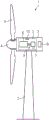
FIG. 1: according to the principle of the wind turbine of the invention,
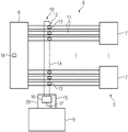
FIG. 2: a schematic view of the power generating assembly of the wind turbine, an
FIG. 3: resistance-temperature diagram of a PTC thermistor.
Detailed Description
Fig. 1 is a schematic view of a wind turbine 1 according to the invention. The wind turbine 1 comprises a tower 2 carrying a nacelle 3 having a hub 4, to which hub 4 at least two wind turbine blades 5 are mounted. A power generation assembly 5 is housed in the nacelle 3, the power generation assembly 5 comprising a generator 6 and a plurality of converters 7, only one of which is shown in figure 1 for clarity. The generator 6 is connected to each of the converters 7 by three electrical connections 8, one for each of the three phases used. For example, the generator 6 may comprise a subsystem connected to a specific converter 7. In one example, the power generation assembly 5 may include twelve converters. The operation of the wind turbine 1, and in particular the operation of the same power generation assembly 5, is controlled by a control device 9, sometimes referred to as a "controller".
The wind turbine 1 may be a direct drive wind turbine or may comprise a gearbox housed in the nacelle 3.
In any case, the power generation assembly 5 further comprises overheating detection means 10 for monitoring the electrical connections 8 for thermal effects caused by phase imbalances, for example by the disconnection of at least one electrical connection 8.
The overheat detection apparatus 10 will be described in more detail with reference to fig. 2. As shown in fig. 2, the generator 6 is connected to the converter 7 by a phase connector 11, which phase connector 11 is in this case a bus bar. On each bus bar, a temperature sensing element 12, in this embodiment a PTC thermistor 13, is located.
Fig. 3 shows a resistance-temperature diagram of the PTC thermistor 13, wherein the resistance is shown on a logarithmic scale. As can be seen, the PTC thermistor 13 may have a slightly negative temperature coefficient up to a point of minimum resistance R min From this point a slightly positive temperature coefficient up to the transition temperature T occurs C . At this transition temperature, a sharp increase in resistance occurs. For example, the transition temperature may be defined as the temperature at which the resistance is twice the minimum resistance value, as exemplarily shown in fig. 3.
In this embodiment, the transition temperature corresponding to the critical temperature of the phase connector 11 is in the interval of 90 ℃ to 200 ℃, for example 120 ℃ or 150 ℃.
Therefore, if the temperature of the corresponding phase connector 11 rises to the transition temperature T C As described above, the resistance of the PTC thermistor is switched to a very high value, so that the PTC thermistor is also referred to as a switching-type PTC thermistor (switching-type PTC thermistor) or simply a switching PTC thermistor (switching PTC thermistor) 13.
As can be seen from fig. 2, the temperature sensing elements 12 are all connected in series along a signal line 14, which signal line 14 may be a simple wire or a single wire cable. The signal line 14 starts and ends at a detection unit 15, which detection unit 15 comprises a resistance measurement circuit 16 for measuring the resistance along the signal line 14. For example, the voltage at which a constant current is forced can be measured by the resistance measurement circuit. It is clear that if the critical temperature is exceeded for at least one PTC thermistor 13, the sensor signal along the signal line 14 will change, because the resistance along the entire signal line 14 will increase strongly. That is, all temperature sensing elements 12 share a common sensor signal, since it is not necessary to detect the exact location at which the critical temperature is exceeded. In other words, knowing that overheating has occurred at least one of the phase connectors 11 is sufficient to conclude that a fault condition exists that requires maintenance.
The detection unit 15 may also comprise a microcontroller 17 for evaluating the common sensor signal, in which case the common sensor signal is processed to derive information which is then transmitted to the connected control device 9. Such overheating information may comprise the actual measured resistance, but is preferably a binary overheating signal, indicating the presence (high resistance, in particular exceeding a threshold) or absence (low resistance) of overheating.
If overheating is detected, an alarm signal is output to an external remote output device, so that an alarm can be output, for example at the manufacturer of the wind turbine and/or at a maintenance service.
Thus, the overheat detection means 10 allows early detection of at least one disconnection event, so that it is generally not necessary to disconnect and/or deactivate the generator 6 or at least one subsystem of the generator 6, since sufficient time remains to resolve a fault condition, such as reconnecting a disconnected phase connector 11.
It is noted that further thermal management may also be provided in the wind turbine 1, for example by using temperature sensors 18, such as Pt100 sensors, at the hottest points of the generator 6 and possibly other locations. As can be seen, the overheat detection means 10 is limited to the phase connector 11. However, multiple overheat detection arrangements 10 for different subsets of the phase connectors 11 may be provided, or even additional overheat detection arrangements 10 may be provided for other groups of locations and/or components of the power generation assembly 5.
While the invention has been described in detail with reference to preferred embodiments, the invention is not limited by the disclosed examples, and other variations can be made from the disclosed examples by those skilled in the art without departing from the scope of the invention.
Claims (13)
1. Wind turbine (1) having a power generating assembly (5) and control means (9) for controlling the power generating assembly (5), the power generating assembly (5) comprising a generator (6), at least one converter (7) connected to the generator (6) and overheat detection means (10),
characterized in that the overheat detection device (10) comprises:
-at least two temperature sensing elements (12) at different positions of the power generation assembly (5), wherein the temperature sensing elements (12) are connected in series along a signal line (14) to provide a common sensor signal and are each adapted to indicate in the common sensor signal that a respective critical temperature at their position is exceeded, and
-a detection unit (15) for evaluating the common sensor signal, the detection unit (15) being connected to the signal line (14).
2. Wind turbine according to claim 1, characterized in that the detection unit (16) or the control device (9) of the wind turbine (1) to which the detection unit (15) is connected is adapted to perform at least one measure in case that at least one of the critical temperatures is detected to be exceeded in the common sensor signal.
3. Wind turbine according to claim 1 or 2, wherein the temperature sensing element (12) is a PTC thermistor (13), wherein the transition temperature for switching the PTC thermistor (13) is the critical temperature.
4. A wind turbine according to claim 3, wherein the detection unit (15) comprises a resistance measurement circuit (16) for measuring the resistance of the temperature sensing element (12) along the signal line (14).
5. Wind turbine according to any of the preceding claims, wherein the power generation assembly (5) comprises phase connectors (11) to connect to the at least one converter (7), wherein a temperature sensing element (12) is located at each phase connector (11).
6. Wind turbine according to claim 5, characterized in that three phase connectors (11) are provided for each converter (7) and/or that the power generating assembly (5) comprises a plurality, in particular 6 to 15, converters (7).
7. Wind turbine according to claim 5 or 6, characterized in that the critical temperature of each connector (11) is 90-200 ℃.
8. Wind turbine according to any of claims 5 to 7, characterized in that the connector (11) is a busbar.
9. Wind turbine according to any of the preceding claims, characterized in that the generator (6) further comprises at least one temperature sensor (18), in particular a Pt100 sensor, for measuring a temperature value, in particular at its hottest location, wherein the temperature sensor (18) is connected to the control device (9).
10. Wind turbine according to any one of the preceding claims, characterized in that said detection unit (15) comprises a box-like housing (20) and is connected to said control device (9), in particular directly through a connector of said housing (20).
11. Method for detecting a fault condition in a power generating assembly (5) of a wind turbine according to any of the preceding claims, wherein a common sensor signal is evaluated at least in a detection unit (15) and at least one measure is performed by the detection unit (15) and/or a control device (9) if the common sensor signal indicates that a critical temperature at least one position of a temperature sensing element is exceeded.
12. Method according to claim 11, wherein at least one of the at least one measure comprises outputting an alarm signal to an external output device, in particular at a manufacturer of the wind turbine (1) and/or at a maintenance service.
13. Method according to claim 11 or 12, characterized in that at least one of said at least one measures comprises deactivating and/or disconnecting at least one subsystem of the generator (6).
Applications Claiming Priority (3)
| Application Number | Priority Date | Filing Date | Title |
|---|---|---|---|
| EP20179660.4 | 2020-06-12 | ||
| EP20179660.4A EP3922843A1 (en) | 2020-06-12 | 2020-06-12 | Wind turbine having an electrical power generation assembly and method for detecting a fault condition in such a wind turbine |
| PCT/EP2021/063603 WO2021249743A1 (en) | 2020-06-12 | 2021-05-21 | Wind turbine having an electrical power generation assembly and method for detecting a fault condition in such a wind turbine |
Publications (1)
| Publication Number | Publication Date |
|---|---|
| CN115667706A true CN115667706A (en) | 2023-01-31 |
Family
ID=71094144
Family Applications (1)
| Application Number | Title | Priority Date | Filing Date |
|---|---|---|---|
| CN202180041989.9A Pending CN115667706A (en) | 2020-06-12 | 2021-05-21 | Wind turbine with a power generation assembly and method for detecting a fault condition in such a wind turbine |
Country Status (4)
| Country | Link |
|---|---|
| US (1) | US20230275532A1 (en) |
| EP (2) | EP3922843A1 (en) |
| CN (1) | CN115667706A (en) |
| WO (1) | WO2021249743A1 (en) |
Families Citing this family (1)
| Publication number | Priority date | Publication date | Assignee | Title |
|---|---|---|---|---|
| EP4215745A1 (en) * | 2022-01-21 | 2023-07-26 | Ørsted Wind Power A/S | Wind turbine cable connector monitoring method and device |
Family Cites Families (2)
| Publication number | Priority date | Publication date | Assignee | Title |
|---|---|---|---|---|
| DE102010051675A1 (en) * | 2010-11-17 | 2012-05-24 | Repower Systems Ag | Wind energy plant and method for operating a wind turbine with temperature monitoring of the transformer |
| ES2613305T3 (en) * | 2013-01-25 | 2017-05-23 | Vestas Wind Systems A/S | Wind turbine control |
-
2020
- 2020-06-12 EP EP20179660.4A patent/EP3922843A1/en not_active Withdrawn
-
2021
- 2021-05-21 US US18/008,264 patent/US20230275532A1/en active Pending
- 2021-05-21 EP EP21728044.5A patent/EP4136343B1/en active Active
- 2021-05-21 WO PCT/EP2021/063603 patent/WO2021249743A1/en unknown
- 2021-05-21 CN CN202180041989.9A patent/CN115667706A/en active Pending
Also Published As
| Publication number | Publication date |
|---|---|
| EP4136343B1 (en) | 2023-12-20 |
| WO2021249743A1 (en) | 2021-12-16 |
| EP4136343A1 (en) | 2023-02-22 |
| US20230275532A1 (en) | 2023-08-31 |
| EP3922843A1 (en) | 2021-12-15 |
Similar Documents
| Publication | Publication Date | Title |
|---|---|---|
| KR101470348B1 (en) | Photovoltaic power generation system having fire prevention apparatus | |
| US8981697B2 (en) | Asset condition monitoring in an electric motor | |
| CN107872196B (en) | Photovoltaic system with voltage limiting device | |
| JP2006517781A (en) | Arc fault detection for SSPC power distribution system | |
| JP3618902B2 (en) | Grid-connected inverter device | |
| US10473708B2 (en) | Methods and systems for real-time monitoring of the insulation state of wind-powered generator windings | |
| US10270317B2 (en) | Motor temperature monitoring | |
| JP6253656B2 (en) | How to monitor multiple electrical energy lines in a cable bundle | |
| EP3928425A1 (en) | Method and apparatus for controlling a power supply to an electrical motor | |
| WO2023272980A1 (en) | Wind turbine control method, apparatus, and system, device and medium | |
| EP4136343B1 (en) | Wind turbine having an electrical power generation assembly and method for detecting a fault condition in such a wind turbine | |
| Boothman et al. | Thermal tracking-A rational approach to motor protection | |
| Maughan et al. | Advances in motor and generator rotor health | |
| Sudha et al. | A novel protecting method for induction motor against faults due to voltage unbalance and single phasing | |
| US11573254B2 (en) | Systems for detecting temperature and current events in a power grid and related methods | |
| CN2349602Y (en) | Motor temp. controller | |
| CN110912084B (en) | Filter capacitor protection method and device and converter | |
| US20230204638A1 (en) | Systems for detecting temperature and current events in a power grid and related methods | |
| Widarsono et al. | Design and Implementation of Protection Relay 3 Phase Induction Motor | |
| KR101491655B1 (en) | Motor Control Device Using Driving Current | |
| CN112689747A (en) | Device for detecting a temperature increase in an electric machine | |
| KR102382799B1 (en) | System of diagnosing receiving end status and load | |
| EP4106186A1 (en) | Method of determining cooling efficiency of an electric motor | |
| Sutar et al. | Induction motor faults mitigation using microcontroller | |
| KR102467410B1 (en) | Secondary side monitoring apparatus of wound-rotor induction motor |
Legal Events
| Date | Code | Title | Description |
|---|---|---|---|
| PB01 | Publication | ||
| PB01 | Publication | ||
| SE01 | Entry into force of request for substantive examination | ||
| SE01 | Entry into force of request for substantive examination |