CN115649217B - Railway vehicle, bogie and primary spring suspension device thereof - Google Patents
Railway vehicle, bogie and primary spring suspension device thereof Download PDFInfo
- Publication number
- CN115649217B CN115649217B CN202211645810.3A CN202211645810A CN115649217B CN 115649217 B CN115649217 B CN 115649217B CN 202211645810 A CN202211645810 A CN 202211645810A CN 115649217 B CN115649217 B CN 115649217B
- Authority
- CN
- China
- Prior art keywords
- spring
- plate
- telescopic mechanism
- baffle
- bogie
- Prior art date
- Legal status (The legal status is an assumption and is not a legal conclusion. Google has not performed a legal analysis and makes no representation as to the accuracy of the status listed.)
- Active
Links
Images


Classifications
-
- Y—GENERAL TAGGING OF NEW TECHNOLOGICAL DEVELOPMENTS; GENERAL TAGGING OF CROSS-SECTIONAL TECHNOLOGIES SPANNING OVER SEVERAL SECTIONS OF THE IPC; TECHNICAL SUBJECTS COVERED BY FORMER USPC CROSS-REFERENCE ART COLLECTIONS [XRACs] AND DIGESTS
- Y02—TECHNOLOGIES OR APPLICATIONS FOR MITIGATION OR ADAPTATION AGAINST CLIMATE CHANGE
- Y02T—CLIMATE CHANGE MITIGATION TECHNOLOGIES RELATED TO TRANSPORTATION
- Y02T30/00—Transportation of goods or passengers via railways, e.g. energy recovery or reducing air resistance
Landscapes
- Vehicle Body Suspensions (AREA)
Abstract
The invention discloses a rail vehicle, a bogie and a primary spring suspension device thereof, wherein the primary spring suspension device of the bogie comprises a framework and an axle box, wherein two upper spring seats are arranged on the framework; a telescopic mechanism is arranged in the mounting hole of the upper spring seat, and a piston rod of the telescopic mechanism is connected with a first baffle plate through a thread pair. The telescopic mechanism is arranged in the primary spring, so that when the transverse rigidity and the longitudinal rigidity of the primary spring need to be adjusted, the telescopic mechanism can be used for pushing, the distance between the upper clamping plate and the lower clamping plate is increased, and the operations of adjusting the spring steering and increasing or replacing various gaskets can be safely and efficiently completed.
Description
Technical Field
The invention relates to the technical field of railway vehicles, in particular to a railway vehicle, a bogie and a primary spring suspension device thereof.
Background
As is well known, a bogie is a portion of a vehicle that directly contacts a track and supports a vehicle body between the track and the vehicle body. The bogie bears the whole weight of the vehicle body and transmits various loads and acting forces from the vehicle body to the wheel rail or from the wheel rail to the vehicle body, so that the vehicle can smoothly pass through a curve.
A bogie primary spring suspension device in the prior art needs to hoist a framework of a bogie in an overhaul workshop or use a precompression device on an operation site to compress and adjust a spring when a fault spring is replaced or the rigidity direction of the spring is adjusted and an adjusting gasket is added in the overhaul process of a vehicle, all the precompression devices adopt a thread pair connection structure, when a screw of the precompression device is loosened and screwed, the operation amount is large, the operation is inconvenient, the labor intensity of workers is high, the risk is high, complex tools are needed to ensure the accuracy of the precompression position of the spring and the safety of the overhaul process, the operation time is long, the maintenance cost of the primary spring suspension device is high, the overhaul efficiency is low, and the overhaul quality is difficult to ensure.
Disclosure of Invention
In order to overcome the defects in the prior art, the invention provides a railway vehicle, a bogie and a primary spring suspension device thereof, which solve the technical problems of high maintenance cost, low maintenance efficiency and difficulty in ensuring the maintenance quality caused by large workload, inconvenience in operation and high risk in the installation and maintenance process of the conventional primary spring suspension device through the structural optimization of the bogie primary spring suspension device.
The invention provides a first-series spring suspension device of a bogie, which comprises a framework and an axle box, wherein two upper spring seats are arranged on the framework, two lower spring seats are arranged on the axle box, an upper clamping plate and a lower clamping plate are arranged between each upper spring seat and the lower spring seat opposite to the upper spring seat, and a first-series spring clamped between the upper clamping plate and the lower clamping plate is arranged on the axle box; the telescopic mechanism is characterized in that a first baffle is connected to a piston rod of the telescopic mechanism through a thread pair, the lower clamping plate comprises a lower skirt portion, the lower skirt portion is arranged in a lower spring seat center hole in a penetrating mode, the first baffle is arranged at the upper end of the lower skirt portion, and the outer diameter of the first baffle is larger than the inner diameter of the lower skirt portion.
Further, still be provided with the mounting panel between punch holder and last spring holder, the hole of mounting panel and telescopic machanism's cylinder body surface fixed connection, the mounting panel passes through the bolt and is connected with last spring holder.
Preferably, the mounting plate comprises a convex conical matching part, the upper spring seat comprises a concave conical mounting hole, and the matching part of the mounting plate is connected with the mounting hole of the upper spring seat in a matching manner.
Furthermore, an adjusting pad is arranged between the contact surfaces of the upper clamping plate and the mounting plate.
Furthermore, an insulating cover and a backing plate are respectively arranged between the contact surfaces of the upper clamping plate and the series of springs.
Furthermore, the telescopic mechanism is a single-action single-piston hydraulic cylinder or a single-action single-piston air cylinder.
Furthermore, a second baffle is connected to the piston rod of the telescopic mechanism through a thread pair, the second baffle is arranged at the lower end of the lower skirt portion of the lower clamping plate, and the outer diameter of the second baffle is larger than the inner diameter of the lower skirt portion and smaller than the diameter of the center hole of the lower spring seat. The second baffle is not arranged on a piston rod of the telescopic mechanism when the train normally runs, and is only used when a series of springs are arranged as a pre-compression device, and the second baffle is detached when the series of springs are in place and put down the train body. And when the gap between the lower clamping plate and the lower spring seat is adjusted, the second resisting plate is required to be installed and used when the lower clamping plate is pushed upwards.
Preferably, the telescopic mechanism is a double-acting single-piston hydraulic cylinder or a double-acting single-piston air cylinder.
Furthermore, the telescopic mechanism is respectively connected with a hydraulic station or a pneumatic pump station through an external interface A and an external interface B; the external interface A is connected with an inlet at one end of the cylinder body, and the external interface B is connected with an inlet at the other end of the cylinder body through a pipeline arranged in the cylinder wall of the cylinder body; a piston capable of sliding along the inner wall of the cylinder body is arranged in the cylinder body between the outer connector A and the outer connector B, and the piston is fixedly connected with a piston rod with partial threads.
Furthermore, the telescopic mechanisms of the two primary spring suspension devices arranged on the two sides of the axle box center are respectively connected with hydraulic or pneumatic pipelines which are connected in parallel or are independently connected with each other. The hydraulic or pneumatic pipeline is connected with external equipment special for maintenance or connected with a hydraulic or pneumatic system of the train.
Furthermore, the lower clamping plate also comprises an upper skirt part, a spring contact surface, a first baffle plate contact surface, a lower port and an adjusting block contact surface, wherein the spring contact surface is in contact with the lower end surface of a series of springs.
Furthermore, the first baffle contact surface is an annular boss, and the working surfaces of the first baffle contact surface, the lower port and the adjusting block contact surface are all planes.
More closely, still be provided with rubber spring between the upper skirt portion of lower plate and telescopic machanism's the cylinder body surface.
As optimization, an adjusting block is further arranged between the lower clamping plate and the lower spring seat.
Further, a third baffle is further installed on a piston rod of the telescopic mechanism through a thread pair, the diameter of the third baffle is larger than that of a central hole of the lower spring seat, and the distance between the third baffle and the first baffle is larger than the maximum amplitude of the extension of the spring.
Further, the series of springs are spiral steel springs or metal rubber springs.
Furthermore, a series of vertical shock absorbers are arranged between the framework and the axle box; the system of vertical shock absorbers are fixedly connected with the framework through the mounting seats.
Furthermore, a transverse stopping lifting lug is hung on the framework and fixed to the top of the axle box through a bolt, and the effect of limiting the transverse maximum displacement of the bogie assembled with the axle box when the bogie passes through a curve is achieved.
The invention also provides a bogie comprising a frame and an axle box located below the frame, the axle box being connected to the frame by a bogie-spring suspension as described in any one of the preceding claims.
The invention further provides a railway vehicle, and the railway vehicle is provided with the bogie provided by the invention.
The invention has the beneficial effects that:
1. according to the invention, the telescopic mechanism is arranged in the primary spring, the first baffle is arranged on the piston rod of the telescopic mechanism through the thread pair, when the transverse and longitudinal stiffness of the primary spring needs to be adjusted, or a gap is adjusted between the upper spring seat and the upper clamp plate, and the gasket is increased, or whether the insulating cover and the backing plate between the contact surfaces of the upper clamp plate and the primary spring are worn or not and are replaced after being checked, the telescopic mechanism can be used for pushing the first baffle to move downwards to be in contact with the contact surface of the first baffle of the lower clamp plate, and the thrust is transmitted to the lower spring seat through the lower clamp plate, and finally the framework is lifted under the pushing of the telescopic mechanism, so that the distance between the upper clamp plate and the lower clamp plate is increased, and the operations of adjusting the spring steering, increasing or replacing various gaskets are smoothly realized.
2. When the telescopic mechanisms of the two primary spring suspension devices on the two sides of the center of the shaft box contract simultaneously, the second baffle plate moves upwards, and the second baffle plate can pull the lower clamping plate to move upwards due to the fact that the outer diameter of the second baffle plate is larger than the inner diameter of the lower skirt portion and smaller than the diameter of the mounting hole of the lower spring seat, the gap between the lower clamping plate and the lower spring seat is increased, and the adjusting block can be adjusted or replaced.
3. The primary spring suspension device can be used as a pre-compression device and a guide post of the primary spring to participate in the installation of the primary spring, and a hydraulic or pneumatic device connected with the primary spring suspension device is provided with a pressure gauge, so that the pre-compression amount is more accurate, the installation precision of the spring is improved, the pre-compression of the spring is not required to be adjusted by screws, the workload is greatly reduced, and the working efficiency is improved.
4. According to the telescopic mechanism of the primary spring suspension devices of each bogie, the outer interfaces of the telescopic mechanism can be independently connected with a hydraulic or pneumatic system or can be switched into parallel connection, and the pressure can be accurately controlled through the pressure meter and various control valves, so that the compression amount of two primary springs on two sides of an axle box can be controlled, the overhaul process is safe and stable, and the assembly and overhaul quality can be guaranteed.
5. According to the primary spring suspension device, the piston cylinder of the telescopic mechanism can be additionally provided with the third baffle, when the whole bogie including the wheel set needs to be lifted and hoisted for maintenance, as the diameter of the third baffle is larger than that of the mounting hole of the lower spring seat, a lifting chain consisting of the upper spring seat, the mounting plate, the telescopic mechanism, the third baffle and the lower spring seat can lift the whole bogie, the function of the primary spring suspension device is increased, and convenience is brought to maintenance.
6. According to the primary spring suspension device, the telescopic mechanism replaces a common screw precompression device, so that convenience is provided for overhauling the primary spring suspension device, the installation space of a bogie is not occupied, the installation space of the bogie is saved, the structure is compact, remote operation is facilitated through a hydraulic or pneumatic pipeline, and the safety and convenience of maintenance are improved.
7. According to the primary spring suspension device, the matching part of the mounting plate is matched and connected with the matching part of the upper spring seat, so that the mounting accuracy and convenience are improved; the telescopic mechanism is a double-acting single-piston hydraulic cylinder or air cylinder, so that the adaptability is improved.
Drawings
FIG. 1 is a schematic view of an arrangement of an embodiment of the present invention mounted on a truck;
FIG. 2 is a partial sectional view of embodiment 1;
FIG. 3 is an enlarged sectional view of portion A of FIG. 1;
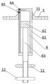
FIG. 4 is a schematic view of the telescopic structure of embodiment 2;
FIG. 5 is a partial sectional view of embodiment 3;
in the figure: 1. the structure comprises a framework, 2, an upper spring seat, 21, a mounting hole, 3, a mounting plate, 31, a matching part, 4, an upper clamping plate, 5, an axle box, 51, a lower spring seat, 52, a central hole, 6, a telescopic mechanism, 61, a cylinder body, 62, a piston, 63, a piston rod, 64, an outer port A,65, an outer port B,7, a lower clamping plate, 71, a lower skirt part, 72, an upper skirt part, 73, a spring contact surface, 74, a first baffle contact surface, 75, a lower port, 76, an adjusting block contact surface, 8, a series of springs, 9, a rubber spring, 10, an adjusting block, 11, a first baffle, 12, a second baffle, 13, a mounting seat, 14, a vertical shock absorber, 15, a transverse baffle lug, 16, an insulating cover, 17, a backing plate, 18 and a third baffle.
Detailed Description
To illustrate the features of the present invention, the present invention is further described below with reference to the accompanying drawings and examples.
Embodiment 1, please refer to fig. 1 and 2, an embodiment of the present invention provides a bogie primary spring suspension device, which includes a frame 1 and an axle box 5, wherein the frame 1 is provided with two upper spring seats 2, the axle box 5 is provided with two lower spring seats 51, an upper clamp plate 4 and a lower clamp plate 7 are arranged between each upper spring seat 2 and the lower spring seat 51 opposite to the upper spring seat 2, and a primary spring 8 clamped between the upper clamp plate 4 and the lower clamp plate 7, a telescopic mechanism 6 is arranged in an installation hole 21 of the upper spring seat 2, the telescopic mechanism 6 includes a cylinder body 61 and a piston rod 63, the cylinder body 61 and the upper spring seat 2 of the telescopic mechanism 6 are detachably connected, and the telescopic mechanism 6 is used as a guide column and sequentially passes through central holes 52 of the upper clamp plate 4, the primary spring 8, the lower clamp plate 7 and the lower spring seat 51; a first baffle 11 is connected to the piston rod 63 of the telescopic mechanism 6 through a thread pair, the lower clamp plate 7 includes a lower skirt portion 71, the lower skirt portion 71 is inserted into the central hole 52 of the lower spring seat 51, the first baffle 11 is arranged at the upper end of the lower skirt portion 71, and the outer diameter of the first baffle 11 is larger than the inner diameter of the lower skirt portion 71.
Still be provided with mounting panel 3 between punch holder 4 and last spring holder 2, the hole of mounting panel 3 and telescopic machanism 6's cylinder body 61 external surface fixed connection, mounting panel 3 passes through the bolt and is connected with last spring holder 2. The mounting plate 3 comprises a convex conical matching portion 31, the upper spring seat 2 comprises a concave conical mounting hole 21, and the matching portion 31 of the mounting plate 3 is matched and connected with the mounting hole 21 of the upper spring seat 2. The matching part 31 of the mounting plate 3 is matched and connected with the mounting hole 21 of the upper spring seat 2, so that the mounting accuracy and convenience are improved.
An adjusting pad (not shown) is arranged between the contact surfaces of the upper clamping plate 4 and the mounting plate 3. An insulating cover 16 and a backing plate 17 are respectively arranged between the contact surfaces of the upper clamping plate 4 and the series of springs 8.
In this embodiment, the telescopic mechanism 6 is a double-acting single-piston hydraulic cylinder or a double-acting single-piston air cylinder.
The lower clamping plate 7 further comprises an upper skirt portion 72, a spring contact surface 73, a first baffle contact surface 74, a lower port 75 and an adjusting block contact surface 76, wherein the spring contact surface 73 is in contact with the lower end surface of the primary spring 8, the first baffle contact surface 74 is an annular boss, and the working surfaces of the first baffle contact surface 74, the lower port 75 and the adjusting block contact surface 76 are all planes.
A rubber spring 9 is also arranged between the upper skirt part 72 of the lower clamping plate 7 and the outer surface of the cylinder body 61 of the telescopic mechanism 6.
An adjusting block 10 is also arranged between the lower clamping plate 7 and the lower spring seat 51.
The primary spring 8 is a spiral steel spring or a metal rubber spring.
A series of vertical shock absorbers 14 are arranged between the framework 1 and the axle box 5; the series of vertical dampers 14 are fixedly connected to the frame 1 by means of mounting seats 13. The vertical shock absorber 14 can improve the running stability and prolong the service life of vehicle parts and line components. A transverse stopping lifting lug 15 is hung on the framework 1, and the transverse stopping lifting lug 15 is fixed to the top of the axle box 5 through a bolt and plays a role in limiting the transverse maximum displacement of the bogie and the axle box during curve passing. Of course, during the maintenance work, the vertical damper 14 and the horizontal stopping lug 15 need to be removed in advance to adjust the height of the axle box 5.
In the embodiment, the telescopic mechanism 6 is arranged in the mounting hole of the upper spring seat, the first baffle 11 is mounted on the piston rod 63 of the telescopic mechanism 6 through a thread pair, when the transverse and longitudinal stiffness of the primary spring needs to be adjusted, or a gap is adjusted between the upper spring seat 2 and the upper clamp plate 4, and a gasket is added, or whether the insulating cover 16 and the cushion plate 17 between the contact surfaces of the upper clamp plate 4 and the primary spring 8 are worn and worn or not are checked and then replaced, the telescopic mechanism 6 can be used for promoting the first baffle 11 to move downwards to be in contact with the first baffle contact surface 74 of the lower clamp plate 7, and the thrust is transmitted to the lower spring seat 51 through the lower clamp plate 7, and finally the framework 1 is lifted under the promotion of the telescopic mechanism 6, so that the distance between the upper clamp plate 4 and the lower clamp plate 7 is increased, and the operations including spring steering adjustment, and increasing or replacing various worn gaskets can be smoothly realized. Of course, the spacer may be split or open at one end to facilitate installation.
The telescopic mechanism 6 in this embodiment is a double-acting single-piston hydraulic cylinder or air cylinder. The telescopic mechanism 6 is a double-acting single-piston hydraulic cylinder or air cylinder, so that the adaptability is improved.
The telescopic mechanism 6 is respectively connected with a hydraulic station or a pneumatic pump station through an external interface A64 and an external interface B65; the external interface A64 is connected with an inlet at one end of the cylinder body 61, and the external interface B65 is connected with an inlet at the other end of the cylinder body 61 through a pipeline arranged in the cylinder wall of the cylinder body 61; a piston 62 which can slide along the inner wall of the cylinder 61 is arranged inside the cylinder 61 between an outer connector A64 and an outer connector B65, and the piston 62 is fixedly connected with a piston rod 63 with partial threads.
The two telescopic mechanisms 6 of the primary spring suspension devices arranged at the two sides of the center of the axle box 5 are respectively and independently connected or connected in parallel on a hydraulic or pneumatic pipeline, and the hydraulic or pneumatic pipeline is a system special for maintenance or self-contained in a train.
The external interface of the telescopic mechanism 6 of the one-spring suspension device of each bogie of the embodiment can be independently connected with a hydraulic or pneumatic system (not shown in the figure) or switched into parallel connection, and the pressure can be accurately controlled through a pressure gauge and various control valves, so that the compression amount of two one-spring springs on two sides of an axle box can be controlled, the maintenance process can be safe and stable, and the assembly and maintenance quality can be guaranteed.
When the two telescopic mechanisms 6 of the primary spring suspension devices on both sides of the axle box 5 are contracted simultaneously, the second baffle 12 moves upwards, and because the outer diameter of the second baffle 12 is larger than the inner diameter of the lower skirt 71 and smaller than the diameter of the central hole 52 of the lower spring seat 51, the second baffle 12 will pull the lower clamp plate 7 to move upwards, so that the gap between the lower clamp plate 7 and the lower spring seat 51 is increased, the adjusting block 10 can be adjusted or replaced, and a buffer damping material such as a rubber pad can be added between the lower clamp plate 7 and the lower spring seat 51 as required.
The primary spring suspension device of embodiment 2 can participate in the installation of a spring as the precompression device and the guide post of a spring, and because the hydraulic or pneumatic device connected with the primary spring suspension device is provided with a pressure gauge, the precompression amount is more accurate, the installation accuracy of the spring is improved, and the precompression of the spring is not adjusted by screws, so that the workload is greatly reduced, and the working efficiency is improved. Replace common screw precompression device with telescopic machanism, not only provide convenience for a spring linkage's maintenance, do not occupy the installation space of bogie moreover, both saved the installation space of bogie, compact structure is convenient for carry out remote operation through hydraulic drive or pneumatic pipeline again, has increased the security and the convenience of maintenance.
In embodiment 3, referring to fig. 5, a third baffle 18 is further installed on a piston rod 63 of the telescopic mechanism 6 through a thread pair, the diameter of the third baffle 18 is larger than the diameter of the central hole 52 of the lower spring seat 51, the third baffle 18 can be installed on site when the bogie is overhauled, and if the third baffle 18 is not removed during train operation for convenience of carrying, the position distance between the third baffle 18 and the first baffle 11 is adjusted to be larger than the maximum amplitude elongation of the primary spring 8 during operation. In the primary spring suspension device of the embodiment, the third baffle 18 is additionally arranged on a piston rod of the telescopic mechanism, when the whole bogie including wheel pairs needs to be lifted and hung for maintenance, because the diameter of the third baffle 18 is larger than that of a central hole 52 of a lower spring seat 51, the whole bogie is lifted by a lifting chain consisting of the framework 1 with the upper spring seat 2, the mounting plate 3, the telescopic mechanism 6, the third baffle 18 and an axle box 5 with the lower spring seat 51, so that the functions of the primary spring suspension device are increased, convenience is provided for maintenance, an external port A64 and an external port B65 of the telescopic mechanism 6 can be connected with an oil pipe of a maintenance hydraulic station during maintenance to adjust the gap between the framework 1 and the axle box 5, one bogie is provided with eight sets of primary spring suspension devices, the telescopic mechanisms of the primary spring suspension devices can be independently connected with the hydraulic station, or can be connected with the hydraulic station after being assembled in parallel, a control valve of the hydraulic station can be operated to arbitrarily adjust the gaps between two wheel pairs of the bogie and four axle boxes and the axle box 5, one side of the primary spring suspension device can also adjust the gap of one side of the axle box, and the bogie, and the operation of the bogie is more convenient and complex bogie, and the practical and the test device is provided with a great application value for the operation of the bogie.
The embodiment of the present invention further provides a bogie, which includes a frame 1 and an axle box 5 located below the frame 1, wherein the axle box 5 is connected to the frame 1 through any one of the bogie-spring suspension devices described above.
The embodiment of the invention also provides a railway vehicle, and the railway vehicle is provided with the bogie provided by the embodiment.
The above embodiments and drawings are only for illustrating the technical solutions of the present invention and are not to be construed as limiting the present invention, and the present invention has been described in detail with reference to the preferred embodiments, it should be understood by those skilled in the art that changes, modifications, additions and substitutions can be made by those skilled in the art without departing from the spirit of the present invention and the scope of the present invention is also defined by the claims. Other related art structures not disclosed in detail herein are prior art in this field.
Claims (9)
1. A bogie primary spring suspension device comprises a framework (1) and an axle box (5), wherein two upper spring seats (2) are arranged on the framework (1), two lower spring seats (51) are arranged on the axle box (5), and the bogie primary spring suspension device is characterized in that: an upper clamping plate (4), a lower clamping plate (7) and a series of springs (8) clamped between the upper clamping plate (4) and the lower clamping plate (7) are arranged between each upper spring seat (2) and the lower spring seat (51) opposite to the upper spring seat (2); a telescopic mechanism (6) is arranged in a mounting hole (21) of the upper spring seat (2), the telescopic mechanism (6) comprises a cylinder body (61) and a piston rod (63), the cylinder body (61) is detachably connected with the upper spring seat (2), and the telescopic mechanism (6) serving as a guide column sequentially penetrates through an upper clamping plate (4), a series of springs (8), a lower clamping plate (7) and a central hole (52) of a lower spring seat (51); a first baffle plate (11) is connected to the piston rod (63) through a thread pair, the lower clamp plate (7) comprises a lower skirt portion (71), the lower skirt portion (71) is arranged in a central hole (52) of the lower spring seat (51) in a penetrating mode, the first baffle plate (11) is arranged at the upper end of the lower skirt portion (71), and the outer diameter of the first baffle plate (11) is larger than the inner diameter of the lower skirt portion (71);
a mounting plate (3) is further arranged between the upper clamping plate (4) and the upper spring seat (2), an inner hole of the mounting plate (3) is fixedly connected with the outer surface of a cylinder body (61) of the telescopic mechanism (6), and the mounting plate (3) is connected with the upper spring seat (2) through a bolt;
an adjusting pad is arranged between the contact surfaces of the upper clamping plate (4) and the mounting plate (3);
an insulating cover (16) and a backing plate (17) are respectively arranged between the contact surfaces of the upper clamping plate (4) and the primary spring (8);
a piston rod (63) of the telescopic mechanism (6) is connected with a second baffle plate (12) through a thread pair, the second baffle plate (12) is arranged at the lower end of the lower skirt part (71), and the outer diameter of the second baffle plate (12) is larger than the inner diameter of the lower skirt part (71) and smaller than the diameter of a central hole (52) of the lower spring seat (51);
an adjusting block (10) is arranged between the lower splint (7) and the lower spring seat (51);
a piston rod (63) of the telescopic mechanism (6) is further connected with a third baffle plate (18) through a thread pair, and the diameter of the third baffle plate (18) is larger than that of a central hole (52) of the lower spring seat (51);
the telescopic mechanism is arranged in the first series of springs, the first baffle is arranged on a piston rod of the telescopic mechanism through a thread pair, when the transverse and longitudinal stiffness of the first series of springs needs to be adjusted, or a gap is adjusted between the upper spring seat and the upper clamp plate, and a gasket is increased, or whether an insulating cover and a base plate between contact surfaces of the upper clamp plate and the first series of springs are worn and replaced after the abrasion is checked, the first baffle can be pushed to move downwards by the telescopic mechanism to be in contact with the contact surface of the first baffle of the lower clamp plate, and the thrust is transmitted to the lower spring seat through the lower clamp plate, and finally the framework is lifted under the pushing of the telescopic mechanism, so that the distance between the upper clamp plate and the lower clamp plate is increased, and the operations of adjusting the spring steering and increasing or replacing various gaskets are smoothly realized;
when the telescopic mechanisms of the two primary spring suspension devices on the two sides of the center of the shaft box contract simultaneously, the second baffle plate moves upwards, and the second baffle plate can pull the lower clamping plate to move upwards to increase the gap between the lower clamping plate and the lower spring seat due to the fact that the outer diameter of the second baffle plate is larger than the inner diameter of the lower skirt part and smaller than the diameter of the mounting hole of the lower spring seat, and the adjusting block can be adjusted or replaced;
still add the third and support the baffle on the telescopic machanism's of spring linkage first, when the maintenance needs to carry and hang the bogie including the wheel pair when whole, because the diameter of third support the baffle is greater than the mounting hole diameter of spring holder down, the promotion chain that comprises by last spring holder, mounting panel, telescopic machanism, third support the baffle, lower spring holder so will mention whole bogie, has increased spring linkage's function, provides convenience for overhauing.
2. The truck-spring suspension as set forth in claim 1, wherein: the telescopic mechanism (6) is a single-action single-piston hydraulic cylinder or a single-action single-piston cylinder.
3. The primary suspension device of claim 1, wherein: the telescopic mechanism (6) is a double-acting single-piston hydraulic cylinder or a double-acting single-piston air cylinder.
4. The truck-spring suspension as set forth in claim 1, wherein: the telescopic mechanism (6) is respectively connected with a hydraulic station or a pneumatic pump station through an external interface A (64) and an external interface B (65); the external interface A (64) is connected with an inlet at one end of the cylinder body (61), and the external interface B (65) is connected with an inlet at the other end of the cylinder body (61) through a pipeline arranged in the cylinder wall of the cylinder body (61); a piston (62) capable of sliding along the inner wall of the cylinder body (61) is arranged in the cylinder body (61) between the outer connector A (64) and the outer connector B (65), and the piston (62) is fixedly connected with a piston rod (63) with partial threads.
5. The truck-spring suspension as set forth in claim 1, wherein: the lower clamping plate (7) further comprises an upper skirt portion (72), a spring contact surface (73), a first resisting plate contact surface (74), a lower port (75) and an adjusting block contact surface (76), and the spring contact surface (73) is in contact with the lower end surface of the primary spring (8).
6. The truck-spring suspension as set forth in claim 5, wherein: and a rubber spring (9) is also arranged between the upper skirt part (72) of the lower clamping plate (7) and the outer surface of the cylinder body (61) of the telescopic mechanism (6).
7. The truck-spring suspension as set forth in claim 1, wherein: a system of vertical shock absorbers (14) are arranged between the framework (1) and the axle box (5), and the system of vertical shock absorbers (14) are fixedly connected with the framework (1) through mounting seats (13).
8. A bogie comprising a frame (1) and an axle box (5) below the frame (1), characterized in that the axle box (5) is connected to the frame (1) by a bogie spring suspension according to any of claims 1 to 7.
9. A rail vehicle comprising a bogie, characterized in that: the bogie is a bogie as claimed in claim 8.
Priority Applications (1)
| Application Number | Priority Date | Filing Date | Title |
|---|---|---|---|
| CN202211645810.3A CN115649217B (en) | 2022-12-21 | 2022-12-21 | Railway vehicle, bogie and primary spring suspension device thereof |
Applications Claiming Priority (1)
| Application Number | Priority Date | Filing Date | Title |
|---|---|---|---|
| CN202211645810.3A CN115649217B (en) | 2022-12-21 | 2022-12-21 | Railway vehicle, bogie and primary spring suspension device thereof |
Publications (2)
| Publication Number | Publication Date |
|---|---|
| CN115649217A CN115649217A (en) | 2023-01-31 |
| CN115649217B true CN115649217B (en) | 2023-03-10 |
Family
ID=85022998
Family Applications (1)
| Application Number | Title | Priority Date | Filing Date |
|---|---|---|---|
| CN202211645810.3A Active CN115649217B (en) | 2022-12-21 | 2022-12-21 | Railway vehicle, bogie and primary spring suspension device thereof |
Country Status (1)
| Country | Link |
|---|---|
| CN (1) | CN115649217B (en) |
Citations (6)
| Publication number | Priority date | Publication date | Assignee | Title |
|---|---|---|---|---|
| JPH10181596A (en) * | 1998-02-16 | 1998-07-07 | Hitachi Ltd | Axle spring gear for rolling stock |
| CN102673596A (en) * | 2011-03-10 | 2012-09-19 | 南车青岛四方机车车辆股份有限公司 | Composite axle box positioning device and processing and assembling method thereof |
| CN107235051A (en) * | 2017-08-09 | 2017-10-10 | 南京中车浦镇城轨车辆有限责任公司 | A kind of rail vehicle reorganizes and outfit the next system's spring load method of adjustment of state |
| CN108349511A (en) * | 2015-10-21 | 2018-07-31 | 利勃海尔运输系统股份有限公司 | Level(l)ing device |
| JP2019073060A (en) * | 2017-10-12 | 2019-05-16 | 日本車輌製造株式会社 | Truck for railway vehicle |
| CN110667633A (en) * | 2019-10-10 | 2020-01-10 | 中车长春轨道客车股份有限公司 | Adjusting device for forming bogie frame and wheel set axle box spring assembly |
Family Cites Families (4)
| Publication number | Priority date | Publication date | Assignee | Title |
|---|---|---|---|---|
| CN201472404U (en) * | 2009-08-11 | 2010-05-19 | 南车青岛四方机车车辆股份有限公司 | Single stage suspension structure of rail car |
| CN202038318U (en) * | 2011-03-10 | 2011-11-16 | 南车青岛四方机车车辆股份有限公司 | Composite axle box positioning device |
| CN103661468B (en) * | 2013-12-13 | 2016-09-14 | 齐齐哈尔轨道交通装备有限责任公司 | Bogie and hanging and locating device of axle box thereof |
| CN215640179U (en) * | 2021-09-13 | 2022-01-25 | 中车青岛四方机车车辆股份有限公司 | Auxiliary device for adjusting height of tie spring of bogie |
-
2022
- 2022-12-21 CN CN202211645810.3A patent/CN115649217B/en active Active
Patent Citations (6)
| Publication number | Priority date | Publication date | Assignee | Title |
|---|---|---|---|---|
| JPH10181596A (en) * | 1998-02-16 | 1998-07-07 | Hitachi Ltd | Axle spring gear for rolling stock |
| CN102673596A (en) * | 2011-03-10 | 2012-09-19 | 南车青岛四方机车车辆股份有限公司 | Composite axle box positioning device and processing and assembling method thereof |
| CN108349511A (en) * | 2015-10-21 | 2018-07-31 | 利勃海尔运输系统股份有限公司 | Level(l)ing device |
| CN107235051A (en) * | 2017-08-09 | 2017-10-10 | 南京中车浦镇城轨车辆有限责任公司 | A kind of rail vehicle reorganizes and outfit the next system's spring load method of adjustment of state |
| JP2019073060A (en) * | 2017-10-12 | 2019-05-16 | 日本車輌製造株式会社 | Truck for railway vehicle |
| CN110667633A (en) * | 2019-10-10 | 2020-01-10 | 中车长春轨道客车股份有限公司 | Adjusting device for forming bogie frame and wheel set axle box spring assembly |
Also Published As
| Publication number | Publication date |
|---|---|
| CN115649217A (en) | 2023-01-31 |
Similar Documents
| Publication | Publication Date | Title |
|---|---|---|
| CN106018097A (en) | Microprocessor control electro-hydraulic servo load-shear test machine | |
| CN208109368U (en) | A kind of air spring rigidity characteristic test apparatus | |
| CN110685195A (en) | Rail transit vibration damping mount | |
| CN111069877A (en) | Hydraulic damper rubber node frock of impressing for rail transit vehicle | |
| CN115649217B (en) | Railway vehicle, bogie and primary spring suspension device thereof | |
| CN210938105U (en) | Precise horizontal machining center | |
| CN201945463U (en) | Cushioning and adjusting device for shafting box spring of railway vehicle bogie | |
| CN217819314U (en) | Three-degree-of-freedom coordinated loading test bed for hinge device | |
| CN208528408U (en) | Stringer assembly welding clamp | |
| CN206940344U (en) | A kind of cold rolling mill hydraulic cylinder changing device | |
| CN203210293U (en) | Dismantling apparatus for air valve lock clamp of diesel engine | |
| CN212239920U (en) | Hydraulic damper rubber node frock of impressing for rail transit vehicle | |
| CN212193035U (en) | Support convenient to ball valve installation | |
| CN210359922U (en) | Welding set is trailed to steel reinforcement cage | |
| CN113118323A (en) | Maintenance device for rail transit | |
| CN110666527A (en) | Precise horizontal machining center | |
| CN206732480U (en) | The liftout component of brake pump pump cover feeder | |
| CN214352120U (en) | Novel water conservancy pipeline is connected supplementaryly device | |
| CN220029257U (en) | Hub axle tube assembling clamp | |
| CN213840485U (en) | Press gas holder mounting structure | |
| CN217996554U (en) | Fixing device for horizontal wheel base of multifunctional crown block | |
| CN206696169U (en) | Egative film fixing device | |
| CN218931544U (en) | Large-angle luffing mechanism for portal crane | |
| CN218428017U (en) | Brake adjuster overhauls auxiliary device | |
| CN115165330B (en) | Three-degree-of-freedom coordinated loading test bed for hinging device |
Legal Events
| Date | Code | Title | Description |
|---|---|---|---|
| PB01 | Publication | ||
| PB01 | Publication | ||
| SE01 | Entry into force of request for substantive examination | ||
| SE01 | Entry into force of request for substantive examination | ||
| GR01 | Patent grant | ||
| GR01 | Patent grant |