CN115648503A - Deburring equipment for air conditioner ABS shell after injection molding - Google Patents
Deburring equipment for air conditioner ABS shell after injection molding Download PDFInfo
- Publication number
- CN115648503A CN115648503A CN202211111586.XA CN202211111586A CN115648503A CN 115648503 A CN115648503 A CN 115648503A CN 202211111586 A CN202211111586 A CN 202211111586A CN 115648503 A CN115648503 A CN 115648503A
- Authority
- CN
- China
- Prior art keywords
- air conditioner
- plate
- base
- deburring
- screw
- Prior art date
- Legal status (The legal status is an assumption and is not a legal conclusion. Google has not performed a legal analysis and makes no representation as to the accuracy of the status listed.)
- Granted
Links
Images


Landscapes
- Milling Processes (AREA)
Abstract
The invention relates to the technical field of air conditioner shell processing, in particular to deburring equipment for an air conditioner ABS shell after injection molding, which comprises a base, a supporting plate, a fixing plate, a rib plate, a supporting unit and a deburring unit, wherein the base is provided with a plurality of through holes; the prior deburring device also has the following problems: the surface of a grinding knife adopted by the device is easy to adhere to burr scraps, so that the machining precision of the air conditioner shell cannot be ensured by the burr scraps; the grinding knife is difficult to remove small burrs, so that the burrs of the air conditioner shell are easy to remain, and the smoothness of the air conditioner shell cannot be ensured; according to the invention, the arc-shaped cutting knife and the deburring knife are used for cutting the burrs of the air conditioner shell, so that burr scraps cannot be attached to the arc-shaped cutting knife or the deburring knife, and the air conditioner shell can be prevented from being scratched or damaged; according to the invention, smaller burrs can be filed by the fan-shaped file and the cylinder file, so that the burr residue is avoided, and the smoothness of the top of the air conditioner shell is ensured.
Description
Technical Field
The invention relates to the technical field of air conditioner shell processing, in particular to deburring equipment for an air conditioner ABS shell after injection molding.
Background
The air conditioner is a common electric appliance in daily life of people, common functions of the air conditioner include refrigeration and heating, and household air conditioners can be divided into a wall-mounted air conditioner, a cabinet air conditioner, a window air conditioner and a ceiling air conditioner according to types, wherein the wall-mounted air conditioner is more comfortable to use and convenient to disassemble and clean daily, so the wall-mounted air conditioner is popular among people.
Wall-hanging air conditioner's shell is dismantled relatively easily, because wall-hanging air conditioner's shell adopts PP plastics material and ABS plastics material more, the mode that adopts injection moulding in the air conditioner shell production process more, because there is the gap between the movable mould seat and the cover half seat of injection molding machine, consequently burr appears easily in its edge of air conditioner shell injection moulding's in-process, consequently, in order to make things convenient for the later stage to use, need clear up the burr of air conditioner shell, the air conditioner shell still adopts the manual work to get rid of the burr most of when the burring at present, it is inefficient to make the burring.
In view of the above-mentioned problem of inefficient deburring, the prior art provides corresponding solutions, such as: the utility model discloses a chinese utility model patent that publication number is CN213351873U discloses a domestic air conditioner plastic casing processing deburring device, and the deburring device that this patent provided drives through the third motor and polishes the sword and rotate, then drives through first slider and polishes the sword and control the removal, and the burr is got rid of to the position about the shell, drives through the second slider simultaneously and polishes the sword and carry out the back-and-forth movement, and the front and back position to the shell is got rid of the burr.
However, the above deburring apparatus has the following problems: 1. this burring device carries out burring processing to air conditioner shell through the sword of polishing, and the sword of polishing can carry out the rotation, consequently the easy burr piece of twining of its outer wall of the in-process of deburring of the sword of polishing for the burr piece influences the sharpness of the sword of polishing easily, and causes the fish tail or the damage at air conditioner shell top easily, thereby can't ensure the machining precision to air conditioner shell.
2. Because the actual working area of the polishing knife is limited, small burrs are difficult to remove, the burrs of the air conditioner shell are easy to remain, the smoothness of the air conditioner shell cannot be ensured, and the polishing knife cannot be correspondingly adjusted according to the shape profile of the air conditioner shell, so that the polishing knife cannot adapt to the air conditioner shells in different shapes, and the polishing knife can easily damage or incompletely deburr the air conditioner shell in the deburring process of the air conditioner shell.
Disclosure of Invention
1. The technical problem to be solved is as follows: the deburring equipment for the air conditioner ABS shell after injection molding can solve the problems pointed out in the background technology.
2. The technical scheme is as follows: in order to achieve the purpose, the invention adopts the following technical scheme that the deburring equipment for the air conditioner ABS shell after injection molding comprises a base, support plates, fixing plates, rib plates, support units and deburring units, wherein the support plates are bilaterally symmetrical at the top of the base and are arranged at equal intervals along the front and back directions of the base, the fixing plates are respectively arranged at the tops of the support plates on the left side and the right side of the base, the rib plates are arranged between the support plates and the fixing plates, the support units are arranged at the tops of the base and positioned at the inner sides of the support plates, and the deburring units are arranged on the fixing plates.
The supporting unit comprises a positioning plate, a swingable jacking plate, a linkage plate, a bearing plate, a wedge-shaped seat, a supporting slide block, a first screw and an auxiliary assembly, wherein: the upper end of the base is bilaterally and symmetrically provided with two supporting groups, the supporting groups are positioned on one side, close to the middle part of the base, of the supporting plate, each supporting group comprises two positioning plates and a linkage plate which are arranged front and back, the upper end of each positioning plate is rotatably provided with a swingable jacking plate, a bearing plate is arranged between each positioning plate and the linkage plate, a limiting chute is formed in each bearing plate, a wedge-shaped seat is slidably arranged in each limiting chute, the top of each wedge-shaped seat is rotatably provided with a supporting slide block, the bottom of each swingable jacking plate is provided with a connecting chute, each supporting slide block is slidably arranged in each connecting chute, a first screw rod is rotatably arranged on each positioning plate, and one end, away from the positioning plates, of each first screw rod penetrates through the wedge-shaped seat in a threaded connection mode and then extends to the rear side of the linkage plate; the support unit can adjust the inclination angle of the swingable jacking plate according to different radians of the air conditioner shell, so that the air conditioner shell is attached to the swingable jacking plate, the stability of the air conditioner shell in the deburring treatment process is further ensured, and the adaptability of the deburring device can be improved.
The burring unit includes guide rail, first electronic slider, supporting spring pole, support frame, removal wheel, a location section of thick bamboo, second screw rod, sliding block, execution piece and cutter conversion components, wherein: the bottom of a left fixed plate and the bottom of a right fixed plate on a base are both provided with guide rails, lead screws are arranged in the guide rails, the outer wall of each lead screw is sleeved with a first electric slider arranged at the bottom of each guide rail in a sliding mode in a threaded connection mode, the bottom of each first electric slider is provided with a support frame through a support spring rod, each support frame is of a U-shaped structure with a downward opening, a moving wheel is rotatably arranged at the opening of each support frame, one side of each support frame, which is far away from the middle of the base, is fixedly provided with a positioning cylinder with a downward opening, the upper end of each positioning cylinder is provided with a second screw rod in a penetrating mode in a threaded connection mode, the bottom of each second screw rod is rotatably provided with a sliding block arranged in the corresponding positioning cylinder in a sliding mode, the bottom of each sliding block is provided with an execution block, and a cutter conversion assembly is arranged in each execution block; the deburring unit can remove burrs on the left side and the right side of the air conditioner shell according to the outline of the top of the air conditioner shell, so that the machining precision of the cutter conversion assembly during deburring can be ensured, and the air conditioner shell can be prevented from being scratched or damaged.
As a preferred technical solution of the present invention, the auxiliary assembly includes a fixing base, a fixing screw, a second electric slider, a connecting plate, a third screw, a displacement plate, a guide post, and a deburring tool, wherein: a fixed seat is arranged on the front side of the base, a sliding groove is formed in one side, close to the middle of the base, of the fixed seat, a fixed screw is rotationally arranged in the sliding groove, a second electric slider is sleeved on the outer wall of the fixed screw in a threaded connection mode, a connecting plate is installed on one side, close to the middle of the base, of the second electric slider, a third screw penetrates through the middle of the connecting plate in a threaded connection mode, a displacement plate is rotationally arranged at the bottom of the third screw, two guide pillars are symmetrically arranged on the top of the displacement plate along the third screw in a left-right mode, the upper ends of the guide pillars slidably penetrate through the connecting plate, and a deburring cutter is installed in the middle of the lower end of the connecting plate; the height of the deburring cutter can be adjusted by the auxiliary assembly according to the thickness of the front end of the air conditioner shell, so that the deburring cutter can be used for deburring air conditioner shells with different thicknesses.
As a preferred technical scheme of the present invention, the cutter switching assembly includes a rotating shaft, a gear, a rack plate, a first swing link, an arc-shaped cutter, a second swing link, a support seat, and a fan-shaped file, wherein: the downside of carrying out the piece has seted up the swing groove, the through-hole that slides has been seted up to swing groove upper end, swing groove middle part is rotated and is provided with the pivot, the fixed cover in middle part of pivot is equipped with the gear, it is provided with the rack board with gear engaged with to slide in the through-hole that slides, the fixed cover of pivot outer wall along the gear bilateral symmetry is equipped with two first pendulum rods, the lower extreme of two first pendulum rods is provided with the camber cutting knife jointly, and the pivot outer wall is equipped with two second pendulum rods along the fixed cover of gear bilateral symmetry, the second pendulum rod is located one side that the gear was kept away from to first pendulum rod, the lower extreme of two second pendulum rods is provided with fan-shaped file through the supporting seat jointly.
As a preferred aspect of the present invention, the tool changer assembly further comprises an impact pad and a magnetic strip, wherein: the front end and the rear end of the rack plate are both provided with impact pads, and two attracted magnetic strips are symmetrically arranged between the impact pads and the execution block along the upper part and the lower part of the rack plate; the position between arc cutting knife and the sector file is converted after the cutter conversion component deburres the air conditioner shell, so that the sector file can file the deburring part at the top of the air conditioner shell, burrs are prevented from being left at the top of the air conditioner shell, and the smoothness of the top of the air conditioner shell is ensured.
As a preferred technical scheme of the invention, two first L-shaped plates corresponding to the position of the execution block are symmetrically arranged on one side of the fixed seat close to the middle part of the base in the left-right direction, and second L-shaped plates corresponding to the position of the execution block are arranged at the lower ends of a left guide rail and a right guide rail on the base; can contradict the front and back both sides of rack board respectively through first L template and second L template, drive the gear through the rack board and take place to rotate to can realize automatic switching arc cutting knife and fan-shaped file, the simple operation.
As a preferred technical scheme of the invention, a through groove is formed in one side of the positioning cylinder, which is far away from the middle part of the base, scale marks are symmetrically formed in the front and back of one side of the positioning cylinder, which is far away from the middle part of the base, along the through groove, a pointer is installed on one side of the sliding block, which is far away from the middle part of the base, and one end of the pointer, which is far away from the sliding block, extends to the outside of the positioning cylinder; when the second screw rod is rotated to adjust the height of the sliding block, the accuracy of adjusting the height of the sliding block can be ensured through the pointer and the scale marks.
According to a preferable technical scheme, the cutting tool bits are detachably arranged on the left side and the right side of the deburring tool, and two cylindrical files are symmetrically arranged on the lower end of the connecting plate along the deburring tool in the left-right direction; can carry out the file to the air conditioner shell front end through cylinder file, avoid the burring department of air conditioner shell front end to remain the burr and influence the later stage and use.
As a preferred technical scheme of the invention, two groups of clamping groups are symmetrically arranged on one side of the fixed seat close to the middle part of the base in a left-right mode, and each clamping group comprises two clamping plates which are vertically arranged; the front end of the air conditioner shell is inserted between the two clamping plates, and then the air conditioner shell is placed on the swingable jacking plate, so that the air conditioner shell can be supported through the clamping plates and the swingable jacking plate, and the stability of the air conditioner shell in the machining process is ensured.
3. Has the advantages that: 1. according to the invention, the arc-shaped cutting knife and the deburring knife are used for cutting the burrs of the air conditioner shell, and the cut burr scraps fall downwards, so that the burr scraps cannot be attached to the arc-shaped cutting knife or the deburring knife, and the influence of the burr scraps on the use effect of the arc-shaped cutting knife or the deburring knife can be avoided, thus the processing precision during deburring can be ensured, and the air conditioner shell can be prevented from being scratched or damaged; the invention can remove the burrs at the front end and the left and right sides of the air conditioner shell and can remove the burrs of the air conditioner shells with different thicknesses, thereby improving the adaptability of the invention; according to the invention, the deburring unit can be used for deburring the air conditioner shell according to the profile of the air conditioner shell, and the height of the arc-shaped cutting knife can be adjusted according to the thickness of the edge of the air conditioner shell, so that burrs on the air conditioner shell can be completely removed.
2. According to the invention, the inclination angle of the swingable jacking plate can be adjusted according to different radians of the air conditioner shell through the supporting unit, so that the air conditioner shell is attached to the swingable jacking plate, and the stability of the air conditioner shell in the deburring treatment process is further ensured.
3. The auxiliary assembly can adjust the height of the deburring knife according to the thickness of the front end of the air conditioner shell, so that the deburring knife can perform deburring treatment on the air conditioner shells with different thicknesses.
4. After the cutter conversion assembly deburres the air conditioner shell, the position between the arc-shaped cutting knife and the fan-shaped file can be automatically converted, so that the fan-shaped file can conveniently file the deburred part at the top of the air conditioner shell, and the operation is convenient and fast.
5. According to the invention, the burr of the air conditioner shell can be filed through the fan-shaped file and the cylinder file, so that the influence on later use caused by the burr of the air conditioner shell remaining at the burr is avoided, the smaller burr can be filed, the burr remaining is avoided, and the smoothness of the top of the air conditioner shell is ensured.
Drawings
The invention is further illustrated with reference to the following figures and examples.
Fig. 1 is a schematic perspective view of the present invention.
Fig. 2 is a schematic perspective view of the present invention (without an air conditioning case).
Fig. 3 is a cross-sectional view (looking from right to left) of the present invention.
Fig. 4 is a partial cutaway view of the support unit of the present invention.
Fig. 5 is a perspective view of the auxiliary assembly of the present invention.
Fig. 6 is a partial cutaway view of the deburring unit of the present invention.
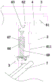
Fig. 7 is a partial enlarged view of fig. 6 a of the present invention.
Fig. 8 is a partial enlarged view of the present invention at B of fig. 6.
Fig. 9 is an initial state diagram of the tool changer assembly of the present invention.
Fig. 10 is a partial enlarged view of the invention at S of fig. 9.
Fig. 11 is an operational state diagram of the tool changer assembly of the present invention.
Fig. 12 is a partial enlarged view of fig. 11 at D of the present invention.
In the figure: 1. a base; 2. a support plate; 3. a fixing plate; 4. a rib plate; 5. a support unit; 51. positioning a plate; 52. a lifting plate can be swung; 53. a linkage plate; 54. a support plate; 55. a wedge-shaped seat; 56. a support slide block; 57. a first screw; 58. an auxiliary component; 581. a fixed seat; 582. fixing the screw rod; 583. a second electric slider; 584. a connecting plate; 585. a third screw; 586. a displacement plate; 587. a guide post; 588. a deburring cutter; 589. a first L-shaped plate; 580. a cylinder file; 590. a clamping and connecting plate; 6. a deburring unit; 61. a guide rail; 611. a second L-shaped plate; 62. a first electric slider; 63. a support spring rod; 64. a support frame; 65. a moving wheel; 66. a positioning cylinder; 661. scale marks are marked; 67. a second screw; 68. a sliding block; 681. a pointer; 69. an execution block; 60. a tool change-over assembly; 601. a rotating shaft; 602. a gear; 603. a rack plate; 604. a first swing link; 605. an arc-shaped cutter; 606. a second swing link; 607. a supporting seat; 608. a fan-shaped file; 609. an impact pad; 610. a magnetic strip; 7. an air conditioner housing.
Detailed Description
The embodiments of the invention will be described in detail below with reference to the drawings, but the invention can be implemented in many different ways as defined and covered by the claims.
Referring to fig. 1, 2 and 3, burring equipment behind air conditioner ABS shell injection moulding, including base 1, backup pad 2, fixed plate 3, floor 4, support element 5 and burring unit 6, a plurality of backup pads 2 are installed to base 1's top bilateral symmetry and along its fore-and-aft direction equidistance, and 2 tops of backup pad of the left and right sides are provided with fixed plate 3 respectively on base 1, install floor 4 between backup pad 2 and the fixed plate 3, and base 1 top just is located backup pad 2 inboards and is provided with support element 5, and burring unit 6 installs on fixed plate 3.
Referring to fig. 2 and 4, the supporting unit 5 includes a positioning plate 51, a swingable lifting plate 52, a linkage plate 53, a supporting plate 54, a wedge-shaped seat 55, a supporting slider 56, a first screw 57, and an auxiliary assembly 58, wherein: the upper end of the base 1 is bilaterally and symmetrically provided with two support groups, the support groups are positioned on one side, close to the middle part of the base 1, of the support plate 2, each support group comprises two positioning plates 51 and a linkage plate 53 which are arranged in front and back, the upper end of each positioning plate 51 is rotatably provided with a swinging jacking plate 52, a bearing plate 54 is installed between each positioning plate 51 and the linkage plate 53, a limiting sliding groove is formed in each bearing plate 54, a wedge-shaped seat 55 is slidably arranged in each limiting sliding groove, the thickness of each wedge-shaped seat 55 is of a structure which is gradually reduced from back to front, a support sliding block 56 is rotatably arranged at the top of each wedge-shaped seat 55, a connecting sliding groove is formed in the bottom of each swinging jacking plate 52, each support sliding block 56 is slidably arranged in each connecting sliding groove, a first screw 57 is rotatably arranged on each positioning plate 51, and one end, far away from the positioning plates 51, of each first screw 57, penetrates through the wedge-shaped seats 55 in a threaded connection mode and extends to the rear side of the linkage plate 53; in this embodiment, a rubber mat (not shown) may be disposed on the top of the swingable lifting plate 52, so that after the air conditioner case 7 is placed on the swingable lifting plate 52, the friction force between the air conditioner case 7 and the rubber mat can be increased by the rubber mat, thereby preventing the air conditioner case 7 from being deviated during the processing.
During specific work, the first screw 57 is rotated, the first screw 57 drives the supporting slide block 56 to move back and forth through the wedge-shaped seat 55, then the first screw 57 can be automatically locked, the supporting slide block 56 drives the swingable jacking plate 52 to rotate along the top of the positioning plate 51, so that the inclination angle of the swingable jacking plate 52 can be adjusted, then the air conditioner shell 7 is placed on the swingable jacking plate 52, the inclination angle of the swingable jacking plate 52 can be adjusted according to different radians of the air conditioner shell 7 through the supporting unit 5, the air conditioner shell 7 is attached to the swingable jacking plate 52, the stability of the air conditioner shell 7 in the deburring process is further ensured, and the adaptability of the deburring device can be improved.
Referring to fig. 5, the auxiliary assembly 58 includes a fixing base 581, a fixing screw 582, a second electric slider 583, a connecting plate 584, a third screw 585, a displacement plate 586, a guide post 587, and a deburring blade 588, wherein: a fixed seat 581 is arranged on the front side of the base 1, two groups of clamping groups are symmetrically arranged on one side of the fixed seat 581 close to the middle part of the base 1 from left to right, and each clamping group comprises two clamping plates 590 which are arranged up and down; two first L-shaped plates 589 corresponding to the execution blocks 69 are symmetrically arranged on one side, close to the middle of the base 1, of the fixing seat 581; a sliding groove is formed in one side, close to the middle of the base 1, of the fixing seat 581, a fixing screw 582 is rotationally arranged in the sliding groove, a second electric slider 583 is sleeved on the outer wall of the fixing screw 582 in a threaded connection mode, the fixing screw 582 is connected, a connecting plate 584 is installed on one side, close to the middle of the base 1, of the second electric slider 583, a third screw 585 penetrates through the middle of the connecting plate 584 in a threaded connection mode, a displacement plate 586 is rotationally arranged at the bottom of the third screw 585, two guide posts 587 are symmetrically arranged on the top of the displacement plate 586 in a left-right mode along the third screw 585, the upper end of each guide post 587 slidably penetrates through the connecting plate 584, the displacement plate 586 can be limited through the guide posts 587, the displacement plate 586 can only move up and down under the action of the guide posts 587 in the rotating process of the third screw 585, and a deburring cutter 588 is installed in the middle of the lower end of the connecting plate 584; cutting tool bits are detachably arranged on the left side and the right side of the deburring tool 588, and two cylinder files 580 are symmetrically arranged on the lower end of the connecting plate 584 along the deburring tool 588 in the left-right direction; in the moving process of the connecting plate 584 along with the second electric slider 583, the front end of the air conditioner shell 7 can be filed by the cylinder file 580, so that the influence of residual burrs at the deburring position at the front end of the air conditioner shell 7 on later use is avoided; in the initial state, the second electric slider 583 is located at the rightmost end of the sliding groove, so that the air conditioner shell 7 can be placed conveniently.
During specific work, the front end of the air conditioner shell 7 is firstly inserted between the two clamping plates 590, then the air conditioner shell 7 is placed on the swingable jacking plate 52, so that the air conditioner shell 7 can be supported through the clamping plates 590 and the swingable jacking plate 52, stability in the machining process of the air conditioner shell 7 is ensured, after the placement of the air conditioner shell 7 is completed, the third screw 585 is rotated, the third screw 585 can drive the displacement plate 586 and the deburring blade 588 to move up and down while rotating, so that the height of the deburring blade 588 is adjusted according to the thickness of the front end of the air conditioner shell 7, the height of the deburring blade 588 is equal to the thickness of the front end of the air conditioner shell 7, then the fixing screw 582 is driven to rotate by the first external reciprocating motor, the second electric slider 583 can reciprocate along the sliding groove under the action of the fixing screw 582, the second electric slider 583 can drive the third screw 586, the displacement plate 585 and the deburring blade 588 to synchronously move through the connecting plate 584, and the deburring blade 588 is attached to the top of the front end of the air conditioner shell 7.
Referring to fig. 6, 7, 8 and 11, the deburring unit 6 includes a guide rail 61, a first motorized slider 62, a support spring bar 63, a support bracket 64, a moving wheel 65, a positioning cylinder 66, a second screw 67, a sliding block 68, an actuating block 69 and a tool switching assembly 60, wherein: the bottoms of the left fixed plate 3 and the right fixed plate 3 on the base 1 are both provided with guide rails 61, the lower ends of the left guide rail 61 and the right guide rail 61 on the base 1 are both provided with second L-shaped plates 611 corresponding to the execution blocks 69, and the second L-shaped plates 611 are of telescopic adjusting structures; a lead screw is arranged in the guide rail 61, a first electric slider 62 which is arranged at the bottom of the guide rail 61 in a sliding manner is sleeved on the outer wall of the lead screw in a threaded connection manner, a support frame 64 is arranged at the bottom of the first electric slider 62 through a support spring rod 63, the support frame 64 is of a U-shaped structure with a downward opening, a moving wheel 65 is arranged at the opening of the support frame 64 in a rotating manner, the support spring rod 63 can contract under the action of external force, the support spring rod 63 can reset under the action of elasticity of the support spring rod 63 without the action of external force, the support spring rod 63 always exerts a contact force on the support frame 64 and the moving wheel 65 and is abutted against the upper end of the air conditioner shell 7, a positioning cylinder 66 with a downward opening is fixedly arranged on one side of the support frame 64 far away from the middle part of the base 1, a second screw rod 67 is arranged at the upper end of the positioning cylinder 66 in a penetrating manner in a threaded connection manner, a sliding block 68 which is arranged in a sliding manner in the positioning cylinder 66 in a rotating manner is arranged at the bottom of the second screw rod 67, an actuating block 69, and a cutter conversion assembly 60 is arranged in the actuating block 69; a through groove is formed in one side, away from the middle of the base 1, of the positioning cylinder 66, scale marks 661 are symmetrically formed in one side, away from the middle of the base 1, of the positioning cylinder 66 along the through groove in a front-back manner, a pointer 681 is installed on one side, away from the middle of the base 1, of the sliding block 68, and one end, away from the sliding block 68, of the pointer 681 extends to the outside of the positioning cylinder 66; when the second screw 67 is rotated to adjust the height of the sliding block 68, the accuracy of adjusting the height of the sliding block 68 can be ensured by the pointer 681 and the scale mark 661; it should be noted that the second screw 67 is rotated to drive the sliding block 68 to move up and down, so that the sliding block 68 can drive the actuating block 69 to move up and down, so that the height of the cutter switching assembly 60 can be adjusted according to the top of the left side and the right side of the air conditioner casing 7, and the cutter switching assembly 60 is attached to the top of the air conditioner casing 7.
In this embodiment, the first screw 57, the second screw 67, and the third screw 585 involved in the present invention are all self-locking screws, and the same as the working principle of the self-locking screws in the prior art, and are not described herein again, and in addition, the first electric slider 62 and the second electric slider 583 can both be provided with air pumps, so when the auxiliary assembly 58 and the deburring unit 6 perform deburring processing on the air conditioner case 7, burrs at the top of the air conditioner case 7 can be blown off by the air pumps, and undesirable phenomena such as scratches on the top of the air conditioner case 7 due to burr residues are avoided.
During specific work, after the air conditioner shell 7 is placed and completed, the moving wheel 65 abuts against the top of the air conditioner shell 7, then the screw rod is driven to rotate through an external second reciprocating motor, the first electric slider 62 slides back and forth along the guide rail 61 under the action of the screw rod, the first electric slider 62 drives the moving wheel 65 to roll at the top of the air conditioner shell 7 through the supporting spring rod 63 and the supporting frame 64, so that the supporting frame 64 drives the cutter conversion assembly 60 to remove burrs on the left side and the right side of the air conditioner shell 7, because the air conditioner shell 7 has a certain radian, and the air conditioner shell 7 is placed in an inclined manner, the supporting frame 64 can move up and down along the moving wheel 65 along the contour of the top of the air conditioner shell 7 in the moving process of the air conditioner shell 7, so that the supporting frame 64 drives the cutter conversion assembly 60 to remove burrs on the left side and the right side of the air conditioner shell 7 according to the contour of the top of the air conditioner shell 7, the machining precision of the cutter conversion assembly 60 in the process of removing the burrs can be ensured, scratch or damage to the air conditioner shell 7 can be prevented, and the moving wheel 65 can drive the cutter conversion assembly 60 to remove the burrs on the air conditioner shells 7 with different thicknesses through the supporting frame 64.
Referring to fig. 8, 9, 10, 11 and 12, the cutter conversion assembly 60 includes a rotating shaft 601, a gear 602, a rack plate 603, a first swing link 604, an arc-shaped cutter 605, a second swing link 606, a support base 607 and a fan-shaped file 608, wherein: a swing groove is formed in the lower side of the execution block 69, a sliding through hole is formed in the upper end of the swing groove, a rotating shaft 601 is rotatably arranged in the middle of the swing groove, a gear 602 is fixedly sleeved in the middle of the rotating shaft 601, a rack plate 603 meshed with the gear 602 is slidably arranged in the sliding through hole, two first swing rods 604 are fixedly sleeved on the outer wall of the rotating shaft 601 along the bilateral symmetry of the gear 602, an arc-shaped cutter 605 is jointly arranged at the lower ends of the two first swing rods 604, two second swing rods 606 are fixedly sleeved on the outer wall of the rotating shaft 601 along the bilateral symmetry of the gear 602, the length of each second swing rod 606 is larger than that of each first swing rod 604, when the rotating shaft 601 rotates, the first swing rods 604 and the second swing rods 606 rotate along with the rotating shaft 601, the second swing rods 606 are located on one side of the first swing rods 604 away from the gear 602, and fan-shaped files 608 are jointly arranged at the lower ends of the two second swing rods 606 through 607; the tool changer assembly 60 further comprises a strike pad 609 and a magnetic strip 610, wherein: the front end and the rear end of the rack plate 603 are both provided with an impact pad 609, and two magnetic strips 610 which are attracted to each other are symmetrically arranged between the impact pad 609 and the execution block 69 up and down along the rack plate 603; the rack plate 603 can be limited and fixed through the magnetic strips 610, so that the rotation of the gear 602 caused by the random movement of the rack plate 603 is avoided, and the first swing rod 604 and the second swing rod 606 can be limited and fixed; in addition, the front side and the rear side of the rack plate 603 can be respectively abutted by the first L-shaped plate 589 and the second L-shaped plate 611, and the rack plate 603 drives the gear 602 to rotate, so that the arc-shaped cutting knife 605 and the fan-shaped file 608 can be automatically switched, and the operation is convenient and fast; in an initial state, the first electric slider 62 is positioned at the foremost side of the guide rail 61, the actuating block 69 is positioned below the first electric slider 62, at this time, the impact pad 609 at the front end of the rack plate 603 abuts against the outer wall of the first L-shaped plate 589, and the magnetic strip 610 of the impact pad 609 at the front end of the rack plate 603 and the magnetic strip 610 at the front end of the actuating block 69 are attracted, so that the first swing link 604 is in a vertical state, and the second swing link 606 is in an inclined state (as shown in fig. 9 and 10); when the inclination angle of the air conditioner casing 7 changes, the distance between the rear base 1 of the air conditioner casing 7 changes accordingly, so that the impact pad 609 cannot be in contact with the second L-shaped plate 611, and therefore, the length of the second L-shaped plate 611 can be adjusted according to the inclination angle of the air conditioner casing 7, so that the impact pad 609 can be in contact with the second L-shaped plate 611, and automatic switching between the arc-shaped cutting knife 605 and the fan-shaped file 608 is achieved.
During specific work, the execution block 69 moves towards the rear side along the guide rail 61 along with the first electric sliding block 62, at the moment, the arc-shaped cutting knife 605 below the execution block 69 is attached to the tops of the left side and the right side of the air conditioner shell 7 and scrapes the burrs avoided by the arc-shaped cutting knife 605, and during the period, the air conditioner shell 7 can apply upward supporting force to the arc-shaped cutting knife 605, so that the arc-shaped cutting knife 605 can perform deburring treatment on the arc-shaped cutting knife 605 according to the outline of the upper end of the air conditioner shell 7, and the burr scraping precision of the air conditioner shell 7 can be ensured; when the first electric slider 62 moves to the rearmost side of the guide rail 61, the actuating block 69 synchronously moves with the first electric slider 62 and drives the rack plate 603 to abut against the outer wall of the second L-shaped plate 611, so that the rack plate 603 moves towards the front side and drives the gear 602 to rotate, the gear 602 rotates and simultaneously can drive the first swing rod 604 and the second swing rod 606 to rotate along with the rotation through the rotating shaft 601, at this time, the first swing rod 604 is in an inclined state, the second swing rod 606 is in a vertical state, and the magnetic strip 610 on the impact pad 609 on the rear side of the rack plate 603 and the magnetic strip 610 on the rear end of the actuating block 69 are attracted (as shown in fig. 11 and 12), at this time, the second swing rod 606 drives the fan-shaped file 608 to abut against the tops of the left side and the right side of the air conditioner shell 7, and then the first electric slider 62 drives the actuating block 69 to move towards the front side, and the actuating block 69 drives the fan-shaped file 608 to file the deburring position on the top of the air conditioner shell 7, so as to avoid residual burrs on the top of the air conditioner shell 7 and ensure the smoothness of the top of the air conditioner shell 7.
In addition, when the arc-shaped cutting knife 605 scrapes burrs on the left side and the right side of the air conditioner shell 7, the arc-shaped cutting knife 605 moves towards the rear side, so that the air conditioner shell 7 applies a reaction force towards the front side to the arc-shaped cutting knife 605, the arc-shaped cutting knife 605 applies a rotating force to the rotating shaft 601 through the first swing rod 604, the rotating shaft 601 drives the rack plate 603 to abut against the rear side through the gear 602, the rack plate 603 cannot move randomly, and the stability of the arc-shaped cutting knife 605 can be ensured; on the contrary, after the arc-shaped cutter 605 and the fan-shaped file 608 are switched, the fan-shaped file 608 moves to the front side and files the burr of the air conditioning casing 7, so that the air conditioning casing 7 applies a reaction force to the fan-shaped file 608 to the rear side, and thus a rotation force can be applied to the rotating shaft 601 through the fan-shaped file 608 and the second swing link 606, so that the rotating shaft 601 locks the rack plate 603 through the rack plate 603, and the stability of the fan-shaped file 608 is ensured.
The working process of the invention is as follows: the first step is as follows: the inclination angle of the swingable lifting plate 52 is adjusted, then the front end of the air-conditioning case 7 is inserted between the two engagement plates 590, the air-conditioning case 7 is placed on the swingable lifting plate 52, and then the air-conditioning case 7 is placed on the swingable lifting plate 52.
The second step: the third screw 585 is rotated and the height of the deburring blade 588 is adjusted according to the thickness of the front end of the air-conditioning case 7, and then the fixing screw 582 is rotated by the first reciprocating motor of the outside, and the second motor-driven slider 583 drives the deburring blade 588 to reciprocate by the fixing screw 582, during which the deburring blade 588 removes burrs from the front end of the air-conditioning case 7, and rasps the burrs from the front end of the air-conditioning case 7 by the cylinder rasp 580.
The third step: the screw rod is driven to rotate by an external second reciprocating motor, the first electric sliding block 62 slides in a reciprocating mode along the guide rail 61 under the action of the screw rod, the moving wheel 65 is driven to roll at the top of the air conditioner shell 7 through the supporting spring rod 63 and the supporting frame 64, and the supporting frame 64 drives the arc-shaped cutting knife 605 to perform deburring processing on the arc-shaped cutting knife according to the outline of the upper end of the air conditioner shell 7 through the execution block 69.
The fourth step: when the first electric sliding block 62 moves to the rearmost side of the guide rail 61, the second L-shaped plate 611 abuts against the rack plate 603 and drives the gear 602 to rotate, the gear 602 can drive the first swing rod 604 and the second swing rod 606 to rotate along with the rotation of the rotating shaft 601 while rotating, so as to change the position between the arc-shaped cutting knife 605 and the fan-shaped file 608, and then the first electric sliding block 62 moves to the front side, at this time, the execution block 69 drives the fan-shaped file 608 to file the deburring position at the top of the air conditioner shell 7, so as to avoid residual burrs at the top of the air conditioner shell 7.
The fifth step: after the deburring of the side of the air-conditioning casing 7 is completed, the first electric slider 62 and the second electric slider 583 are restored to the initial state, and then the air-conditioning casing 7 after the machining is completed is taken down.
The above description is only a preferred embodiment of the present invention and is not intended to limit the present invention, and various modifications and changes may be made by those skilled in the art. Any modification, equivalent replacement, or improvement made within the spirit and principle of the present invention should be included in the protection scope of the present invention.
Claims (8)
1. Burring equipment behind air conditioner ABS shell injection moulding, including base (1), backup pad (2), fixed plate (3), floor (4), support element (5) and burring unit (6), its characterized in that: the top bilateral symmetry of base (1) just installs a plurality of backup pads (2) along its fore-and-aft direction equidistance, and backup pad (2) top of the left and right sides is provided with fixed plate (3) respectively on base (1), installs between backup pad (2) and fixed plate (3) floor (4), and base (1) top just is located backup pad (2) inboard and is provided with support element (5), and burring unit (6) are installed on fixed plate (3), wherein:
the supporting unit (5) comprises a positioning plate (51), a swingable jacking plate (52), a linkage plate (53), a bearing plate (54), a wedge-shaped seat (55), a supporting sliding block (56), a first screw rod (57) and an auxiliary assembly (58), wherein: the upper end of the base (1) is bilaterally symmetrically provided with two support groups, the support groups are located on one side, close to the middle part of the base (1), of the support plate (2), each support group comprises two positioning plates (51) and a linkage plate (53) which are arranged in front and back, the upper end of each positioning plate (51) is rotatably provided with a swingable jacking plate (52), a bearing plate (54) is installed between each positioning plate (51) and each linkage plate (53), a limiting sliding groove is formed in each bearing plate (54), a wedge-shaped seat (55) is slidably arranged in each limiting sliding groove, a support sliding block (56) is rotatably arranged at the top of each wedge-shaped seat (55), a connection sliding groove is formed in the bottom of each swingable jacking plate (52), each support sliding block (56) is slidably arranged in each connection sliding groove, a first screw rod (57) is rotatably arranged on each positioning plate (51), and one end, far away from each positioning plate (51), of each first screw rod (57), penetrates through each wedge-shaped seat (55) in a threaded connection mode and extends to the rear side of each linkage plate (53);
the deburring unit (6) comprises a guide rail (61), a first electric sliding block (62), a supporting spring rod (63), a supporting frame (64), a moving wheel (65), a positioning cylinder (66), a second screw rod (67), a sliding block (68), an execution block (69) and a cutter conversion assembly (60), wherein: guide rail (61) are all installed to the bottom of two fixed plates (3) about on base (1), be provided with the lead screw in guide rail (61), the lead screw outer wall is equipped with through threaded connection's mode cover and slides and set up first electronic slider (62) in guide rail (61) bottom, support frame (64) are installed through supporting spring pole (63) in first electronic slider (62) bottom, support frame (64) are the U type structure of opening decurrent, the opening part of support frame (64) is rotated and is provided with removal wheel (65), one side fixed mounting that base (1) middle part was kept away from in support frame (64) has opening decurrent location section of thick bamboo (66), the mode through threaded connection of location section of thick bamboo (66) upper end is run through and is provided with second screw rod (67), the bottom of second screw rod (67) is rotated and is provided with and slides and sets up at inside sliding block (68) of location section of thick bamboo (66), carry out piece (69) is installed to the bottom of sliding block (68), carry out the inside cutter conversion subassembly (60) that is provided with of carrying out block (69).
2. The air conditioner ABS shell deburring apparatus after injection molding of claim 1, characterized in that: auxiliary assembly (58) include fixing base (581), clamping screw (582), second electric slider (583), connecting plate (584), third screw (585), displacement plate (586), guide pillar (587) and deburring knife (588), wherein: the front side of base (1) is provided with fixing base (581), the groove of sliding has been seted up to one side that fixing base (581) is close to base (1) middle part, the inslot internal rotation that slides is provided with clamping screw (582), clamping screw (582) outer wall is equipped with second electric slider (583) through threaded connection's mode cover, connecting plate (584) is installed to one side that second electric slider (583) are close to base (1) middle part, the mode that passes through threaded connection in connecting plate (584) middle part is provided with third screw (585), the bottom of third screw (585) is rotated and is provided with displacement board (586), displacement board (586) top is provided with two guide pillars (587) along third screw (585) bilateral symmetry, guide pillar (587) upper end slides and runs through connecting plate (584), the mid-mounting of connecting plate (584) lower extreme has unhairing bayonet (588).
3. The air conditioner ABS shell deburring apparatus after injection molding of claim 1, characterized in that: cutter converting component (60) includes pivot (601), gear (602), rack plate (603), first pendulum rod (604), arc type cutting knife (605), second pendulum rod (606), supporting seat (607) and fan-shaped file (608), wherein: the swing groove has been seted up to the downside of carrying out piece (69), the through-hole that slides has been seted up to swing groove upper end, swing groove middle part is rotated and is provided with pivot (601), the fixed cover in middle part of pivot (601) is equipped with gear (602), it is provided with rack plate (603) with gear (602) engaged with to slide in the through-hole that slides, the fixed cover of pivot (601) outer wall along gear (602) bilateral symmetry is equipped with two first pendulum rod (604), the lower extreme of two first pendulum rod (604) is provided with arc type cutting knife (605) jointly, and the fixed cover of pivot (601) outer wall along gear (602) bilateral symmetry is equipped with two second pendulum rod (606), second pendulum rod (606) are located one side that gear (602) were kept away from to first pendulum rod (604), the lower extreme of two second pendulum rod (606) is provided with fan-shaped file (608) through supporting seat (607) jointly.
4. The air conditioner ABS shell deburring apparatus after injection molding of claim 3, characterized in that: the tool changer assembly (60) further comprises a strike pad (609) and a magnetic strip (610), wherein: the front end and the rear end of the rack plate (603) are respectively provided with an impact pad (609), and two magnetic strips (610) which are attracted to each other are symmetrically arranged between the impact pad (609) and the execution block (69) along the rack plate (603).
5. The air conditioner ABS shell deburring apparatus after injection molding of claim 2, characterized in that: the fixing base (581) is close to one side of the middle of the base (1), and is symmetrically provided with two first L-shaped plates (589) corresponding to the execution blocks (69) in a left-right mode, and the lower ends of the left guide rail (61) and the right guide rail (61) on the base (1) are respectively provided with a second L-shaped plate (611) corresponding to the execution blocks (69).
6. The air conditioner ABS shell post-injection-molding deburring device of claim 1, wherein: one side that base (1) middle part was kept away from in a location section of thick bamboo (66) has been seted up logical groove, and has been seted up scale mark (661) along leading to groove front and back symmetry in one side that base (1) middle part was kept away from in a location section of thick bamboo (66), and pointer (681) are installed to one side of keeping away from base (1) middle part of sliding block (68), and the one end that sliding block (68) were kept away from in pointer (681) extends to the outside of a location section of thick bamboo (66).
7. The air conditioner ABS shell post-injection-molding deburring apparatus as claimed in claim 2, wherein: the left and right sides of deburring sword (588) all are provided with the cutting tool bit through the detachable mode, and the lower extreme of connecting plate (584) is provided with two cylinder files (580) along deburring sword (588) bilateral symmetry.
8. The air conditioner ABS shell deburring apparatus after injection molding of claim 2, characterized in that: the fixing base (581) is close to one side and the bilateral symmetry in the middle of base (1) and is provided with two sets of centre gripping groups, and every centre gripping group is including two joint board (590) of arranging from top to bottom.
Priority Applications (1)
| Application Number | Priority Date | Filing Date | Title |
|---|---|---|---|
| CN202211111586.XA CN115648503B (en) | 2022-09-13 | 2022-09-13 | Deburring equipment for air conditioner ABS shell after injection molding |
Applications Claiming Priority (1)
| Application Number | Priority Date | Filing Date | Title |
|---|---|---|---|
| CN202211111586.XA CN115648503B (en) | 2022-09-13 | 2022-09-13 | Deburring equipment for air conditioner ABS shell after injection molding |
Publications (2)
| Publication Number | Publication Date |
|---|---|
| CN115648503A true CN115648503A (en) | 2023-01-31 |
| CN115648503B CN115648503B (en) | 2023-10-20 |
Family
ID=84982991
Family Applications (1)
| Application Number | Title | Priority Date | Filing Date |
|---|---|---|---|
| CN202211111586.XA Active CN115648503B (en) | 2022-09-13 | 2022-09-13 | Deburring equipment for air conditioner ABS shell after injection molding |
Country Status (1)
| Country | Link |
|---|---|
| CN (1) | CN115648503B (en) |
Citations (25)
| Publication number | Priority date | Publication date | Assignee | Title |
|---|---|---|---|---|
| SE7407806L (en) * | 1973-06-14 | 1974-12-16 | Sundstrand Syracuse | |
| US4787134A (en) * | 1986-09-19 | 1988-11-29 | Mazda/Motor Corporation | Automatic tool exchange apparatus |
| JPH11347866A (en) * | 1998-06-02 | 1999-12-21 | Nagase Integurekkusu:Kk | Machine tool |
| CN104308263A (en) * | 2014-09-17 | 2015-01-28 | 重庆和剑机械制造有限公司 | Mechanism special for removing burrs in transverse through hole of cylinder part |
| US20180085882A1 (en) * | 2016-09-24 | 2018-03-29 | Citic Dicastal Co.,Ltd | Burr removing device for wheel |
| CN107984321A (en) * | 2017-12-28 | 2018-05-04 | 新昌县长城空调部件有限公司 | A kind of air supply rate surface burr remover |
| US20180215007A1 (en) * | 2016-06-29 | 2018-08-02 | Chongqing University | Abrasive belt grinding device for profile precision consistency |
| JP2019111592A (en) * | 2017-12-21 | 2019-07-11 | ダイハツ工業株式会社 | Deburring device |
| CN110744398A (en) * | 2019-12-26 | 2020-02-04 | 烟台工程职业技术学院(烟台市技师学院) | Computer metal keyboard shell grinding device |
| CN111230641A (en) * | 2020-03-19 | 2020-06-05 | 嵊州佳想汽车用品有限公司 | Be used for car different grade type wheel hub burr equipment of polishing |
| CN210678105U (en) * | 2019-09-30 | 2020-06-05 | 天津源通自动化设备有限公司 | A burr grinding device for upper plate |
| CN210818839U (en) * | 2019-09-30 | 2020-06-23 | 杭州蓝本汽车电器有限公司 | Automobile air conditioner controller shell deburring device |
| CN213351873U (en) * | 2020-08-17 | 2021-06-04 | 苏州塑豪机械科技有限公司 | Deburring device for machining plastic shell of household air conditioner |
| CN213411461U (en) * | 2019-12-16 | 2021-06-11 | 瓦房店龙工机械制造有限公司 | Grinding device is used in screw rod production |
| CN113211695A (en) * | 2021-05-25 | 2021-08-06 | 深圳市磐锋精密技术有限公司 | Automatic auxiliary production equipment for continuous injection molding |
| CN214109920U (en) * | 2020-12-16 | 2021-09-03 | 大连保利泵阀密封材料有限公司 | Universal grinding machine for processing rubber sealing ring |
| CN113442352A (en) * | 2021-07-01 | 2021-09-28 | 陈栋 | Rubber ring burr removing equipment |
| CN215092674U (en) * | 2021-05-31 | 2021-12-10 | 芜湖锐研机电设备有限公司 | Surface grinding device behind air condition compressor shell shaping |
| CN215216502U (en) * | 2021-04-12 | 2021-12-17 | 汉福启东空气处理设备有限公司 | Air conditioner dehumidification unit utilizing sensible heat of compressor exhaust |
| CN215700853U (en) * | 2021-09-24 | 2022-02-01 | 深圳市倍斯科技有限公司 | Clamp device for grinding oblique angle for numerical control machine tool |
| CN215748340U (en) * | 2021-06-04 | 2022-02-08 | 山东永锦电气股份有限公司 | Grinding device is used in rectifier shell production |
| CN114193289A (en) * | 2021-12-13 | 2022-03-18 | 中国船舶重工集团公司第七一六研究所 | Equipment and method for continuously feeding and discharging and continuously polishing arc plate for ship |
| CN114310540A (en) * | 2021-08-30 | 2022-04-12 | 中国科学院沈阳自动化研究所 | Equipment and method for automatically grinding weld joint of flow channel of casing by robot |
| CN216913190U (en) * | 2022-02-15 | 2022-07-08 | 河南通臻科技有限公司 | Deburring device for machining special-shaped thin-wall shell |
| CN114808572A (en) * | 2022-06-08 | 2022-07-29 | 四川大学 | Tool setting method for profile-shaped vertical inclined grinding wheel of steel rail |
-
2022
- 2022-09-13 CN CN202211111586.XA patent/CN115648503B/en active Active
Patent Citations (25)
| Publication number | Priority date | Publication date | Assignee | Title |
|---|---|---|---|---|
| SE7407806L (en) * | 1973-06-14 | 1974-12-16 | Sundstrand Syracuse | |
| US4787134A (en) * | 1986-09-19 | 1988-11-29 | Mazda/Motor Corporation | Automatic tool exchange apparatus |
| JPH11347866A (en) * | 1998-06-02 | 1999-12-21 | Nagase Integurekkusu:Kk | Machine tool |
| CN104308263A (en) * | 2014-09-17 | 2015-01-28 | 重庆和剑机械制造有限公司 | Mechanism special for removing burrs in transverse through hole of cylinder part |
| US20180215007A1 (en) * | 2016-06-29 | 2018-08-02 | Chongqing University | Abrasive belt grinding device for profile precision consistency |
| US20180085882A1 (en) * | 2016-09-24 | 2018-03-29 | Citic Dicastal Co.,Ltd | Burr removing device for wheel |
| JP2019111592A (en) * | 2017-12-21 | 2019-07-11 | ダイハツ工業株式会社 | Deburring device |
| CN107984321A (en) * | 2017-12-28 | 2018-05-04 | 新昌县长城空调部件有限公司 | A kind of air supply rate surface burr remover |
| CN210678105U (en) * | 2019-09-30 | 2020-06-05 | 天津源通自动化设备有限公司 | A burr grinding device for upper plate |
| CN210818839U (en) * | 2019-09-30 | 2020-06-23 | 杭州蓝本汽车电器有限公司 | Automobile air conditioner controller shell deburring device |
| CN213411461U (en) * | 2019-12-16 | 2021-06-11 | 瓦房店龙工机械制造有限公司 | Grinding device is used in screw rod production |
| CN110744398A (en) * | 2019-12-26 | 2020-02-04 | 烟台工程职业技术学院(烟台市技师学院) | Computer metal keyboard shell grinding device |
| CN111230641A (en) * | 2020-03-19 | 2020-06-05 | 嵊州佳想汽车用品有限公司 | Be used for car different grade type wheel hub burr equipment of polishing |
| CN213351873U (en) * | 2020-08-17 | 2021-06-04 | 苏州塑豪机械科技有限公司 | Deburring device for machining plastic shell of household air conditioner |
| CN214109920U (en) * | 2020-12-16 | 2021-09-03 | 大连保利泵阀密封材料有限公司 | Universal grinding machine for processing rubber sealing ring |
| CN215216502U (en) * | 2021-04-12 | 2021-12-17 | 汉福启东空气处理设备有限公司 | Air conditioner dehumidification unit utilizing sensible heat of compressor exhaust |
| CN113211695A (en) * | 2021-05-25 | 2021-08-06 | 深圳市磐锋精密技术有限公司 | Automatic auxiliary production equipment for continuous injection molding |
| CN215092674U (en) * | 2021-05-31 | 2021-12-10 | 芜湖锐研机电设备有限公司 | Surface grinding device behind air condition compressor shell shaping |
| CN215748340U (en) * | 2021-06-04 | 2022-02-08 | 山东永锦电气股份有限公司 | Grinding device is used in rectifier shell production |
| CN113442352A (en) * | 2021-07-01 | 2021-09-28 | 陈栋 | Rubber ring burr removing equipment |
| CN114310540A (en) * | 2021-08-30 | 2022-04-12 | 中国科学院沈阳自动化研究所 | Equipment and method for automatically grinding weld joint of flow channel of casing by robot |
| CN215700853U (en) * | 2021-09-24 | 2022-02-01 | 深圳市倍斯科技有限公司 | Clamp device for grinding oblique angle for numerical control machine tool |
| CN114193289A (en) * | 2021-12-13 | 2022-03-18 | 中国船舶重工集团公司第七一六研究所 | Equipment and method for continuously feeding and discharging and continuously polishing arc plate for ship |
| CN216913190U (en) * | 2022-02-15 | 2022-07-08 | 河南通臻科技有限公司 | Deburring device for machining special-shaped thin-wall shell |
| CN114808572A (en) * | 2022-06-08 | 2022-07-29 | 四川大学 | Tool setting method for profile-shaped vertical inclined grinding wheel of steel rail |
Non-Patent Citations (2)
| Title |
|---|
| "ST124周边导轨磨床", 精密制造与自动化, no. 03 * |
| 刘洪斌;王增平;王金兰;: "雷达罩内壁电厚度测量与磨削校正系统研究", 测控技术, no. 08 * |
Also Published As
| Publication number | Publication date |
|---|---|
| CN115648503B (en) | 2023-10-20 |
Similar Documents
| Publication | Publication Date | Title |
|---|---|---|
| CN216681512U (en) | Abrasive cutting machine with highlight chamfer function | |
| CN115648503A (en) | Deburring equipment for air conditioner ABS shell after injection molding | |
| CN219005224U (en) | Rear floor burr-proof shearing and punching device | |
| CN114193267B (en) | Equipment for removing burrs on inner surface and outer surface of spring and working method thereof | |
| CN112757092B (en) | Surface polishing device for processing round chopping board | |
| CN114734566A (en) | Plastic product trimming device | |
| CN212218036U (en) | Acrylic edge trimmer | |
| CN210435916U (en) | Desktop type polishing repair machine | |
| CN112936033A (en) | Automatic processing system of furniture board | |
| CN113043098A (en) | Circuit board milling flutes device | |
| CN218312572U (en) | Deburring equipment for original standard production | |
| CN117300641B (en) | Trimming die for metal product production | |
| CN220863543U (en) | Deburring equipment is used in working of plastics production | |
| CN214214559U (en) | Plastic product edge trimmer | |
| CN220093733U (en) | Cutting grinding device | |
| CN215661370U (en) | Trimming device for rubber processing | |
| CN219685722U (en) | Cutting structure for production of automobile seat dust cover | |
| CN218614293U (en) | Cutting machine capable of protecting clamping | |
| CN117584180B (en) | Plastic plate production device and production method | |
| CN215019746U (en) | Nose tip former | |
| CN219882061U (en) | Burr removing device for cast part | |
| CN219170405U (en) | Edging machine | |
| CN219310636U (en) | Incomplete limit trimming means is used to window frame corner | |
| CN219053555U (en) | Edge trimming equipment for machining steel inlaid guide rail | |
| CN214869786U (en) | Automatic grinding wheel adjusting mechanism |
Legal Events
| Date | Code | Title | Description |
|---|---|---|---|
| PB01 | Publication | ||
| PB01 | Publication | ||
| SE01 | Entry into force of request for substantive examination | ||
| SE01 | Entry into force of request for substantive examination | ||
| CB02 | Change of applicant information |
Address after: 226200 No. 38, Jiangtian Road, Binhai Industrial Park, Qidong City, Nantong City, Jiangsu Province Applicant after: Hanfu Qidong Environmental Technology Co.,Ltd. Address before: 226200 No. 38, Jiangtian Road, Binhai Industrial Park, Qidong City, Nantong City, Jiangsu Province Applicant before: HANFU QIDONG AIR TREATMENT EQUIPMENT Co.,Ltd. |
|
| CB02 | Change of applicant information | ||
| GR01 | Patent grant | ||
| GR01 | Patent grant |