CN115646044A - Cleaning and filtering synchronous control method in water treatment system - Google Patents
Cleaning and filtering synchronous control method in water treatment system Download PDFInfo
- Publication number
- CN115646044A CN115646044A CN202111383421.3A CN202111383421A CN115646044A CN 115646044 A CN115646044 A CN 115646044A CN 202111383421 A CN202111383421 A CN 202111383421A CN 115646044 A CN115646044 A CN 115646044A
- Authority
- CN
- China
- Prior art keywords
- filter element
- filter
- cleaning
- barrel
- driving mechanism
- Prior art date
- Legal status (The legal status is an assumption and is not a legal conclusion. Google has not performed a legal analysis and makes no representation as to the accuracy of the status listed.)
- Pending
Links
Images


Landscapes
- Filtration Of Liquid (AREA)
Abstract
The invention is suitable for the technical field of sewage treatment, and provides a synchronous control method for cleaning and filtering in a water treatment system, wherein two filter cores connected with a driving beam are lifted synchronously and switched to work, and when one filter core is used for filtering, the other filter core is cleaned; when the filtered filter element is filtered, the filter element is rotated to a cleaning station, and meanwhile, the cleaned filter element is also rotated to a working station. The invention can effectively prevent the filter element from blocking the hole and stably work.
Description
Technical Field
The invention belongs to the technical field of sewage treatment, and particularly relates to a synchronous control method for cleaning and filtering in a water treatment system.
Background
With the development of economy and the advancement of science and technology, the living conditions of people are widely improved, and the corresponding environmental protection problem faced by people is more severe. Among them, water pollution caused by discharge of various domestic sewage and industrial and agricultural wastewater has become a problem to be solved urgently.
The sewage usually contains less dense source floes, as well as heavier suspended matter and large clumps of dirt. Sewage treatment is a process of purifying sewage to meet the requirement of discharging the sewage into a certain water body or reusing the sewage. In the sewage treatment process, the most important link is solid-liquid separation, and the solid-liquid separation is generally realized by adopting a filtering or precipitating mode in the prior art.
In the existing water treatment technology, a method is adopted to add a water treatment agent (such as a flocculating agent) into sewage so as to generate flocculate in a water body, and then clear liquid is taken out through filtration or sedimentation so as to achieve the process of sewage purification.
Disclosure of Invention
The invention aims to overcome the problem of hole blockage of a filter element in the prior art and provides a synchronous control method for cleaning and filtering in a water treatment system.
The invention is realized by the following steps:
a synchronous control method for cleaning and filtering in a water treatment system drives two filter elements connected with a cross beam to synchronously lift and switch, and when one filter element filters, the other filter element is cleaned; when the filter element after filtration finishes filtering, the filter element rotates to a cleaning station, and meanwhile, the cleaned filter element also rotates to a working station.
Step 1: preparation work:
the filter vat is in the high position, put into the sewage in the filter vat first, add water treatment agent, after reacting fully, form many flocculates in the sewage;
step 2: filtration and cleaning
The filter element is controlled to descend, water enters the filter element through the filter holes on the outer wall of the filter element in the filter barrel, and flocculate is discharged outside the filter element, namely is left in the filter barrel. At the moment, the filter element rotates, so that the possibility of hole blocking is reduced; after a certain amount of water is stored in the filter element, starting a liquid pumping mechanism to pump away the water (clear liquid) in the filter element;
the other end of the filter element rotates in the cleaning barrel while the filter element descends, and the nozzle is controlled to spray water to clean the outer wall of the filter element; until the filter element descends to the lowest end; the water after cleaning is recycled or discharged to other places;
the filter element descends to the lowest position, and after the water in the filter element is completely pumped out, the process is finished;
and 3, step 3: and (3) switching the filter element:
the electric push rod controls the filter elements to ascend to the highest position, and the cross beam rotation driving mechanism drives the cross beam to rotate 180 degrees, so that 2 filter elements are exchanged left and right; one cycle is over;
and then entering the step 1 to carry out the cycle of the next period.
A system for performing the cleaning and filtration synchronization of sewage treatment for performing the method of the present invention comprises a synchronization lift mechanism, a filter element assembly, a cleaning tank and a filter tank;
the synchronous lifting mechanism comprises a lifting driving mechanism and a cross beam; two ends of the beam are respectively and correspondingly connected with the 2 groups of filter element assemblies; the middle part of the beam is connected with the movable end of the lifting driving mechanism, and the lifting driving mechanism drives the beam to lift so as to drive the 2 groups of filter element assemblies to lift synchronously;
the cleaning barrel and the filtering barrel are respectively arranged at two sides of the lifting driving mechanism; after the 2 groups of filter element assemblies descend, the 2 groups of filter element assemblies correspondingly descend into the cleaning barrel and the filter barrel;
a spray head for cleaning is arranged in the cleaning barrel;
the synchronous lifting mechanism or the cross beam is also provided with a cross beam rotation driving mechanism for driving the cross beam to rotate.
The beam rotation driving mechanism is a motor-gear driving mechanism. Specifically, be equipped with the bearing on the crossbeam, the upper end (or called push rod upper end) cartridge of lift actuating mechanism's end of moving is in the shaft hole of bearing, and the crossbeam can be rotatory around the push rod upper end like this, and the outer lane of bearing is fixed in driven gear, is equipped with at least one motor on the crossbeam, and crossbeam rotation driving motor promptly is equipped with the driving gear in the pivot of motor, and the motor is preferred 2, plays the balancing action. The two motors are started to drive the cross beam to rotate. The motor is arranged on the beam through the motor bracket.
Other mechanisms for driving the rotation of the beam are also possible. The crossbeam is fixedly connected with the upper end of the push rod, and the driving mechanism drives the lifting driving mechanism to integrally rotate.
The shower nozzle sets up along the circumference of wasing the bucket.
An annular water supply pipe is arranged in the cleaning barrel, the spray heads are arranged on the annular water supply pipe, and the spray heads are uniformly arranged along the circumferential direction of the annular water supply pipe.
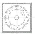
The radial inclination angle theta of the spray head relative to the filter element is more than 0 and less than 30 degrees. Such as 15 deg. or the like.
The filter element assembly is a rotary filter element assembly, and the filter element can rotate automatically under the driving of the driving mechanism.
The cleaning machine also comprises a controller, and the synchronous lifting mechanism, the beam rotation driving mechanism, the filter element assembly and the cleaning mechanism are all controlled by the controller.
An alignment mechanism is also included. The device is used for aligning the filter element with the filter barrel and the cleaning barrel, and is controlled by a code disc or an angle sensor combined with a motor, and belongs to the prior art.
The bottom of the synchronous lifting mechanism is provided with an oblique supporting piece. The support forbidden end is fixed and stable.
The lifting driving mechanism is an electric push rod or a hydraulic cylinder type driving mechanism.
The both ends of crossbeam pass through the jib and link to each other with filter element group spare. Or can be directly butted with the filter element without a suspender.
The filter vat is butted with the dosing module, and the butting means that the solution output by the dosing module enters the filter vat. The chemical dosing module is used for adding a water treatment agent solution into the container, and in addition, the front end of the filter barrel is connected with the front-stage filter device, namely clear liquid output by the front-stage filter device enters the filter barrel for further treatment.
It should be noted that the bottom of the container (cleaning barrel and filtering barrel) is provided with a blow-off pipe for discharging the filtered solid slag, an electrically controlled valve is arranged on the blow-off valve, the valve is closed during filtering, and is opened when the solid slag needs to be discharged, the valve is controlled by the MCU, and the specific control method is the prior art.
Compared with the prior art, the filter element lifting assembly provided by the invention is provided with the lifting driving mechanism which can be used for lifting the filter element, so that the filter element can be conveniently mounted and dismounted, and meanwhile, the height of the filter element in a container can be adjusted in a lifting way when the filter element works, so that the filter element can conveniently achieve the optimal filtering effect; moreover, two ends of one cross beam are connected with two groups of filter element assemblies, so that on the basis of synchronous lifting of the filter elements of the two-stage treatment pool, balance and stability during lifting can be guaranteed, the conditions of blocking and the like during lifting are avoided, and the practicability is high. In addition, still be equipped with the rotatory mechanism of drive crossbeam to make the filter core can filter and wash in turn, the structure is ingenious, and easy to carry out, thereby furthest has avoided stifled hole, and the guarantee sewage filtering operation can last, stable, reliable, circulation and high-efficient going on.
The water treatment device corresponding to the method of the invention has the following characteristics:
1. the water treatment device (water treatment unit) has compact and integrated structure; the occupied space is small; flexible configuration is facilitated; 2. automatic operation; the device can be unattended; remote monitoring; the equipment can automatically run under the control of the controller, unattended operation can be realized, remote control can be realized after the controller is connected with a communication module, and on-site data can be transmitted to a remote server or a data terminal (such as a smart phone) to realize remote monitoring; therefore, the automation degree is high, and the digitization degree is high; the control can also be realized by adopting a simulated relay control system, and the specific control is the existing mature technology. 3. The modular concept is adopted, and the modular operation is realized; can be flexibly connected in parallel or cascaded; the module type operation is convenient for later maintenance; 4. the water treatment device (water treatment unit) has a self-cleaning function; the whole process and structure are ingenious in design concept; the processing capacity is strong. 5. Ultraviolet sterilization and ozone sterilization can be further added at the water outlet pipe;
the water treatment device of the invention has the core characteristics that: automatic lifting (lifting action, cleaning filter element and circulating action), self-cleaning, wastewater purification by filtration and circulating action.
In conclusion, the water treatment device has high automation degree, can realize the refined treatment of the wastewater or the water to be purified, is easy to implement, has compact structure, is convenient to flexibly move and combine, is a great improvement on the existing water treatment equipment, and has great social benefit and economic benefit.
Reinforced module (add medicine module promptly), have following characteristics: (1) The control quantity is accurate, and the control quantity is measured by taking the capacity of the concave part as a unit, for example, the concave part can contain 5 grams or 10 grams of materials, and the control is accurate. (2) The feeding speed is controllable, the feeding amount can be controlled by controlling the rotating speed of the roller driving motor, and the feeding amount can also be adjusted by replacing different rollers. (3) The hopper upper end can be sealed, and the hopper lower extreme can be sealed through the running roller, can not lead to the material contact a large amount of air in the hopper, and the leakproofness is better. And (4) through the inclined channel, the equipment is prevented from being corroded by water vapor. And the lower end sealing port of the unique inclined channel is designed, the material pushes the baffle open under the action of gravity to enter the liquid medicine barrel, and the lower end port of the inclined channel is closed by the baffle without the material, so that the water vapor is prevented from flowing to the feeding device. (5) The position of the roller is positioned through the positioning mechanism, so that accurate feeding is realized. In a word, the feeding device has the advantages of compact structure, controllable precision and easy implementation. (6) This kind of reinforced module combines feeding device and liquid medicine bucket together organically, and occupation space is little, compact structure.
In summary, the water treatment apparatus (core equipment) of the present invention is combined (organically combined) with the preceding stage equipment and the chemical dosing module, which complement each other, and can realize comprehensive, fast and efficient treatment of sewage.
Drawings
FIG. 1 is a schematic view showing the structure of a water treatment apparatus according to an embodiment of the present invention (in a state where a filter element module is lowered);
FIG. 2 is a schematic view of the water treatment apparatus according to an embodiment of the present invention in a state in which the filter element assembly is raised;
FIG. 3 is a schematic view of the cleaning and filtration synchronized system for wastewater treatment with the filter element raised to the highest position;
FIG. 4 is a schematic view of the system for simultaneous cleaning and filtration of wastewater treatment with the filter element lowered to the lowest position;
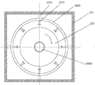
FIG. 5 is a schematic view of the arrangement of the nozzles in the cleaning tank (orthographic nozzles);
FIG. 6 is a schematic view showing the arrangement of the nozzles in the washing tub (inclined nozzles);
FIG. 7 is a schematic view of a base support;
FIG. 8 is a schematic view of a beam drive mechanism;
FIG. 9 is a schematic view (front sectional view) of a roller structure with a strip-shaped recess;
FIG. 10 is a schematic view (cross-sectional side view) of a roller with strip-shaped recesses;
FIG. 11 is a schematic view (front sectional view) of a roller with a circular recess;
FIG. 12 is a schematic view (cross-sectional side view) of a roller with a circular recess;
FIG. 13 is a schematic structural view (front view) of a roller-type quantitative feeding device;
FIG. 14 is a schematic structural view (side view) of a roller-type metering device;
FIG. 15 is a schematic view of the position of a concave portion of the roller-type quantitative feeding device;
fig. 16 is a schematic structural view (front view) of a roller-type dosing module;
fig. 17 is a schematic structural view (side view) of a roller type dosing module;
FIG. 18 isbase:Sub>A sectional view taken along line A-A of FIG. 17;
FIG. 19 is a front view of a preceding stage (front end) water treatment apparatus (device);
FIG. 20 is a side view of a preceding stage (front end) water treatment apparatus (plant);
FIG. 21 is a perspective view of a preceding stage (front end) water treatment apparatus (device);
FIG. 22 is a cross-sectional view B-B of FIG. 19;
FIG. 23 isbase:Sub>A cross-sectional view A-A of FIG. 20;
FIG. 24 is a sectional view of a preceding stage (front end) water treatment apparatus (device);
FIG. 25 is a top view of a backing (front end) water treatment apparatus (device) (without a backing pump).
The reference numbers illustrate:
100. a water treatment device;
200. a water treatment unit; 210. a container; 220. a filter element assembly; 221. a filter element; 222. a drive member; 222a, a driving motor; 222b, a speed regulating gear; 223. a lifting platform;
300. a filter element lifting assembly; 310. a lifting drive mechanism; 320. a cross member.
2001-base, 2002-push rod, 2003-motor support, 2004-crossbeam rotation driving motor, 2005-driving gear, 2006-driven gear, 2007-suspender, 2008-filter element rotating shaft, 2009-cleaning pipe, 2010-cleaning barrel, 2011-filter barrel, 2012-bearing, 2013-spray head, 2014-connecting piece, 2015-oblique support piece and 2016-bottom plate.
256-liquid medicine barrel, 265-oblique feeding channel. 266-a recess; 267-hopper, 269-strip-shaped concave part, 271-round concave part, 276-blanking roller, 277-roller rotating shaft, 278-baffle rotating shaft, 279-baffle, 280-pipe wall, 281-supporting frame and 281-blanking driving motor; 283-an upper support frame, 284-a lower support frame and 285-a liquid medicine stirring motor; 286-roller mounting plate.
1-1 outer barrel, 1-2 backing stage bearings, 1-3 driven gears, 1-4 backing stage liquid pumps, 1-5 water pumping pipes, 1-6 driving motors, 1-7 driving gears, 1-8 main rotating shafts, 1-9 sewage suction pumps, 1-10 filter barrels, 1-11 water inlet holes, 1-12 bottom valves, 1-13 cascade pipes, 1-14 backing stage water inlet pipes and 1-15 backing stage water outlet pipes. 1-16 lower brackets; 1-17 upper supports, 1-18 synchronous belts, 1-19 driving synchronous wheels and 1-20 driven synchronous wheels.
Detailed Description
In order to make the objects, technical solutions and advantages of the present invention more apparent, the present invention is described in further detail below with reference to the accompanying drawings and embodiments. It should be understood that the specific embodiments described herein are merely illustrative of the invention and are not intended to limit the invention.
Example 1
Referring to fig. 1 to 8, a system for synchronous cleaning and filtering for sewage treatment includes a synchronous lifting mechanism, a filter element assembly, a cleaning barrel 2010 and a filtering barrel 2011;
the synchronous lifting mechanism comprises a lifting driving mechanism (preferably an electric push rod) and a cross beam 320; two ends of the beam are respectively and correspondingly connected with the 2 groups of filter element assemblies; the middle part of the beam is connected with the movable end of the lifting driving mechanism, and the lifting driving mechanism drives the beam to lift so as to drive the 2 groups of filter element assemblies to lift synchronously;
the cleaning barrel and the filtering barrel are respectively arranged at two sides of the lifting driving mechanism; after the 2 groups of filter element assemblies descend, the 2 groups of filter element assemblies correspondingly descend into the cleaning barrel and the filter barrel;
a spray head 2013 for cleaning is arranged in the cleaning barrel;
the synchronous lifting mechanism or the cross beam is also provided with a cross beam rotation driving mechanism for driving the cross beam to rotate.
The beam rotation driving mechanism is a motor-gear driving mechanism. Specifically, the bearing 2012 is installed on the crossbeam, the upper end (or called push rod upper end) of the moving end of the lifting driving mechanism is inserted in the shaft hole of the bearing, so that the crossbeam can rotate around the upper end of the push rod, the outer ring of the bearing is fixed in the driven gear 2006, the crossbeam is provided with at least one motor, namely the crossbeam rotation driving motor 2004, the rotating shaft of the motor is provided with driving gears, and the number of the motors is preferably 2, so that a balance effect is achieved. The two motors are started to drive the cross beam to rotate. The motor is mounted on the cross beam by a motor bracket 2003.
Other mechanisms for driving the rotation of the beam are also possible. The crossbeam is fixedly connected with the upper end of the push rod, and the driving mechanism drives the lifting driving mechanism to integrally rotate.
The shower nozzle sets up along the circumference of wasing the bucket.
An annular water supply pipe is arranged in the cleaning barrel, the spray heads are arranged on the annular water supply pipe, and the spray heads are uniformly arranged along the circumferential direction of the annular water supply pipe.
In one case, referring to FIG. 5, the spray heads are radially positioned so that when the filter element is rotated, the sprayed water washes the outer wall of the filter element;
in another aspect, referring to FIG. 6, the radial tilt angle θ of the spray head relative to the filter element is 0 < θ < 30. Such as 15 deg. or the like. And the inclined direction faces the rotating direction of the filter element, so that the surface of the filter element is basically opposite to the direction of the sprayed water column, namely the relative speed is higher, the surface of the filter element is more favorably cleaned, and impurities in filter holes on the surface of the filter element are washed away.
The filter element assembly is a rotary filter element assembly, and the filter element can rotate automatically under the driving of the driving mechanism.
The water treatment system also comprises a controller, and the synchronous lifting mechanism, the beam rotation driving mechanism, the filter element assembly and the cleaning mechanism are all controlled by the controller. The specific control method is the existing mature technology.
An alignment mechanism is also included. The device is used for aligning the filter element with the filter barrel and the cleaning barrel, and is controlled by a code disc or an angle sensor combined with a motor, and belongs to the prior art.
The bottom of the synchronous lift mechanism has an oblique support 2015. The support forbidden end is immovable and stable.
The lifting driving mechanism is an electric push rod or a hydraulic cylinder type driving mechanism.
The cleaning and filtering synchronous control method in the water treatment system comprises the following steps:
the electric push rod drives the two filter elements connected with the cross beam to synchronously lift and switch, and when one filter element filters, the other filter element is cleaned; when the filtered filter element is filtered, the filter element is rotated to a cleaning station, and meanwhile, the cleaned filter element is also rotated to a working station.
The specific description is as follows:
step 1: preparation work:
referring to fig. 3, the filter vat is in a high position, sewage is firstly put into the filter vat, then the water treatment agent is added, and after the reaction is fully carried out, a plurality of flocculates are formed in the sewage;
step 2: filtration and cleaning
Referring to fig. 4, the filter element is controlled to descend, in the filter vat, water enters the filter element through the filter holes on the outer wall of the filter element, and flocculates are discharged outside the filter element, i.e. remain in the filter vat. At the moment, the filter element rotates, so that the possibility of blocking the hole is reduced; after a certain amount of water is stored in the filter element, starting a liquid pumping mechanism to pump away the water (clear liquid) in the filter element;
the other end of the filter element rotates in the cleaning barrel while the filter element descends, and the nozzle is controlled to spray water to clean the outer wall of the filter element; until the filter element descends to the lowest end; the water after cleaning is recycled or discharged to other places.
The filter element descends to the lowest position, and after the water in the filter element is completely pumped out, the process is finished;
and step 3: and (3) switching the filter element:
the electric push rod controls the filter elements to rise to the highest position, and the cross beam rotation driving mechanism drives the cross beam to rotate 180 degrees, so that 2 filter elements are exchanged left and right; one cycle is over;
and then entering the step 1 to carry out the cycle of the next period.
Some specifications regarding water treatment units:
referring to fig. 1-2, a filter cartridge lifting assembly 300 includes: a lift drive mechanism 310; a cross beam 320, one end of which is fixedly connected with one external set of filter element assemblies 220 and the other end of which is fixedly connected with the other external set of filter element assemblies 220; the middle of the cross beam 320 is fixedly connected to the moving end (in this embodiment, the upper end of the electric push rod) of the lifting driving mechanism 310.
In the foregoing, it is concrete, filter core lifting unit 300 that this embodiment provided is applicable to in the system that has 1 water treatment unit and a cleaning unit, filter core subassembly 220 among this water treatment unit can be connected respectively at its both ends of crossbeam 320, and then, when lift actuating mechanism 310 carries out the descending motion that rises, crossbeam 320 synchronous motion rather than fixed connection, and then drive two sets of filter core subassemblies 220 synchronous rising or descending, can be on the basis that the filter core 221 that realizes water treatment unit goes up and down in step, still can guarantee balance and steady (the middle part of crossbeam 320 and lift actuating mechanism 310 fixed connection, and then make crossbeam 320 atress balanced, in order to guarantee to go up and down steadily), the circumstances such as card appears when can avoiding going up and down, therefore, the clothes hanger is strong in practicability, can make things convenient for the installation of filter core 221 to dismantle, can make things convenient for filter core 221 to reach best filter effect. In the above, the lifting driving mechanism 310 is specifically an electric push rod or a hydraulic cylinder, and may be specifically determined according to the actual weight of the filter element assembly 220, for example, when the filter element assembly 220 is heavy, a hydraulic cylinder with a strong load-bearing capacity may be used. In the foregoing, specifically, the cross beam 320 is connected with the filter element assembly 220 through a suspension rod, the suspension rod is connected with the lifting platform of the filter element assembly through a bolt connection or other mechanisms such as pins, and the specific connection mode is the existing mature technology.
The embodiment also provides a water treatment device 100, which comprises a water treatment unit 200, a cleaning unit and, for example, 2 filter element lifting assemblies 300;
wherein, water treatment unit 200 includes container 210 and filter element group 220, and container 210 is constructed for holding sewage, and filter element group 220 includes filter element 221, is used for driving the rotatory driving piece 222 of filter element and is used for the lift platform 223 of fixed driving piece 222, and filter element 221 sets up in container 210, and the both ends of crossbeam 320 respectively with 2 lift platforms 223 fixed connection. Before filtering, sewage is required to be injected into a container, a water treatment agent solution is added into the sewage, the reaction lasts for a period of time to ensure that the water treatment agent fully reacts, flocculate is formed in the water, then a filter element is arranged for filtering, and clear water (filtered water) is pumped out from the filter element; and carrying out subsequent processing.
Specifically, this water treatment facilities 100, when lift actuating mechanism 310 goes up and down, accessible crossbeam 320 drives two sets of filter element group 220 and goes up and down (filter core 221 goes up and down and is realized by filter element group 220 whole lift), can be on the basis of the synchronous lift of filter element group 220 in realizing two sets of water treatment unit 200, because the middle part fixed connection lift actuating mechanism 310 of crossbeam 320, and filter element group 220 is connected at both ends, and then can guarantee its atress is balanced, and then can guarantee filter element group 220 relative balance and steady when going up and down, the circumstances such as card death appear when can avoiding going up and down, therefore, the clothes hanger is strong in practicability, can make things convenient for the installation of filter core 221 to dismantle, can make things convenient for filter element 221 to reach best filter effect.
In the foregoing, specifically, the driving element 222 includes a driving motor 222a and a speed-regulating gear 222b (which may also be a belt pulley), the driving motor 222a and the speed-regulating gear 222b are fixed on the lifting platform 223, the driving motor 222a can provide power, and the speed-regulating gear 222b can ensure smooth rotation, wherein an output shaft of the driving motor 222a is connected with an input end of the speed-regulating gear 222b, and an output end of the speed-regulating gear 222b is connected with the connecting shaft of the filter element 221.
In the above, specifically, the cross beam 310 is configured to be plate-shaped and is in threaded connection with the lifting platform 223 (e.g., through a bolt connection, etc.), the cross beam 310 is plate-shaped and can be conveniently assembled and matched with the lifting platform 223, and meanwhile, the two plates are in threaded connection, so that the connection reliability and precision are high, and the cost is low.
In the above, referring to fig. 2, the filter element 221 is configured to cover a disc shape, a cylinder shape or other shapes, and is formed by two disc-shaped members, and the surface thereof is configured with filter holes, the number of the filter elements 221 is two, and the filter elements are arranged on a common rotating shaft, and the double filter elements are arranged, so that the filtering effect can be ensured, and the problem that the filtering function cannot be realized when a certain filter element 221 is blocked is avoided.
In the foregoing, specifically, the container 210 is a square barrel body, the material of the container 210 is stainless steel, and the material of the container 210 is stainless steel, so that the situation of rusting after containing sewage can be avoided.
In summary, compared with the prior art, the filter element lifting assembly provided by the invention is provided with the lifting driving mechanism for lifting the filter element, so that the filter element can be conveniently mounted and dismounted, and meanwhile, the height of the filter element in the container can be adjusted in a lifting way when the filter element works, so that the filter element can conveniently achieve the optimal filtering effect; moreover, two ends of one cross beam are connected with two groups of filter element assemblies, so that on the basis of synchronous lifting of the filter elements of the two-stage treatment pool, balance and stability during lifting can be guaranteed, the conditions of blocking and the like during lifting are avoided, and the practicability is high.
The medicine feeding module:
referring to fig. 9-16, a roller-type dosing module includes a roller-type dosing device and a liquid medicine barrel;
the rotary roller type quantitative feeding device is positioned above the liquid medicine barrel, and a discharge port of the rotary roller type quantitative feeding device is butted with a feed port on the liquid medicine barrel;
the liquid medicine barrel is provided with a liquid medicine stirring mechanism for stirring liquid medicine; the liquid medicine mechanism comprises a stirring shaft and a stirring blade in the liquid medicine barrel and a liquid medicine stirring motor arranged on the liquid medicine barrel; the rotary roller type quantitative feeding device comprises a hopper, a blanking roller, a support frame and a blanking channel; the blanking roller is driven by a blanking driving motor; the blanking roller is arranged below the feed opening of the hopper, and the roller surface of the blanking roller is in contact with the feed opening; the blanking roller is arranged on a roller mounting plate extending out of the lower part of the hopper, or the blanking roller is arranged on the support frame; the roller surface of the blanking roller is provided with at least one concave part; when the blanking roller does not rotate, the blanking roller can seal a blanking port at the lower end of the hopper to prevent the material in the hopper from leaking; when the blanking roller wheel rotates, the concave part can prevent the materials in the hopper from being taken out, and the materials are output to the liquid medicine barrel through the feeding channel, and the outlet of the feeding channel is the discharge hole.
The lower end of the support frame has a plurality of legs 284; the liquid medicine barrel is arranged in a space surrounded by the plurality of supporting legs, in another mode, the supporting frame singly supports the feeding device, the liquid medicine barrel does not need to be supported, and the supporting frame can be arranged on the side part of the liquid medicine barrel and is not shown in the figure; or the support frame is fixed on the liquid medicine barrel.
The supporting frame is provided with a liquid medicine pump 252, and a liquid inlet pipe of the liquid medicine pump is inserted in the liquid medicine barrel.
The feed channel is an oblique feed channel 265, which can also be a vertical feed channel, but the oblique feed channel makes the material enter gently, i.e. slide into the cartridge.
The depressed part is a plurality of, arranges equally along the circumference of blanking running roller.
The blanking driving motor is driven by a frequency converter, the speed can be adjusted, the adjustment of the dosing amount in unit time is realized, the frequency can be manually adjusted by the frequency converter or controlled by an MCU, and the frequency converter is controlled by the MCU.
The blanking driving motor is controlled by the MCU, and the blanking roller is provided with a position detection sensor; the position detection sensor is a Hall sensor, a coded disc or a photoelectric switch, and the liquid medicine pump is controlled by the MCU; MCU is connected with communication module, the remote monitoring of being convenient for.
The liquid outlet pipe of the liquid medicine pump is connected with the interior of a container in the water treatment device, so that the solution in the liquid medicine barrel is pumped into the container.
The periphery of the filter element is provided with a filter screen, the diameter of the mesh on the filter screen is 0.1-2mm, the filter screen is arranged according to specific application occasions and requirements, if the filter effect is good, the filter holes with small diameter can be selected, and if the filter efficiency is high, the filter holes with large diameter can be selected. Or a plurality of water treatment devices are connected in series, and the diameter of the filter hole of the front stage is larger than that of the filter hole of the rear stage. The filter screen can be the wire net, and is preferred, and the filter screen can also adopt etching technique production, and intensity is high. The size of the filter holes is illustrated schematically, and is not intended to represent the actual ratio of filter holes to equipment.
Specifically, the method comprises the following steps: the rotary roller type quantitative dosing device comprises a hopper 267, a blanking roller 276, a support frame 281 and a blanking channel; the blanking roller is driven by a blanking driving motor 281; the blanking roller is arranged below the feed opening of the hopper, and the roller surface of the blanking roller is in contact with the feed opening; the blanking roller is arranged on a roller mounting plate 286 extending from the lower part of the hopper, and the roller surface of the blanking roller is provided with 2 concave parts; when the blanking roller does not rotate, the blanking roller can seal a blanking port at the lower end of the hopper to prevent the material in the hopper from leaking; when the blanking roller rotates, the concave part can prevent the materials in the hopper from being taken out, and the materials are output through the feeding channel; the feeding channel is an inclined feeding channel 265, the inclined feeding channel enables the materials to smoothly enter, namely, the materials slide into the liquid medicine barrel, the support frame is a square frame, and the bottom of the square frame is provided with a support leg 284; the number of the concave parts is 2, and the concave parts are arranged in equal intervals along the circumferential direction of the blanking roller wheel, namely are symmetrically distributed around the roller; the blanking driving motor is driven by a frequency converter, the speed can be adjusted, the adjustment of the dosing amount in unit time is realized, the frequency can be manually adjusted by the frequency converter or controlled by an MCU (microprogrammed control unit), and the frequency converter is controlled by the MCU; the blanking driving motor is controlled by the MCU, and the blanking roller is provided with a position detection sensor; the position detection sensor is a Hall sensor, a coded disc or a photoelectric switch; MCU is connected with communication module, the remote monitoring of being convenient for.
The rotary roller type quantitative dosing device is arranged in the water treatment system and is used as a part of the water treatment system and used for feeding a water treatment agent into a liquid medicine barrel in the water treatment system.
The preceding stage apparatus is explained as follows:
the forestage equipment is used for carrying out primary filtration or called forestage filtration on the breeding wastewater (such as pig manure water), the diameter of a filter hole of the forestage equipment is larger than that of a filter hole of the post-stage equipment (core treatment equipment, namely the water treatment device of the invention), and the diameter of the filter hole of the forestage equipment is controlled to be 0.5-1.2mm. The connection between the preceding-stage equipment and the subsequent-stage equipment means that water output by a water outlet pipe of the preceding-stage equipment enters a filter vat (namely a container) of the subsequent-stage equipment.
As shown in fig. 19 to 25, the preceding stage water treatment apparatus comprises a lower frame 1 to 16, an outer barrel 1 to 1, a filter barrel 1 to 10, a liquid inlet, and a driving mechanism for driving the filter barrel to rotate; the lower bracket comprises a frame and a plurality of support legs for supporting the frame; the outer barrel is fixed on the lower bracket; the filter barrel is arranged in the outer barrel; a plurality of filter holes are arranged on the wall of the filter barrel; the filter vat is a rotary filter vat with a main rotating shaft; the outer barrel is provided with a supporting platform, the supporting platform is provided with a front-stage bearing, and a main rotating shaft 1-8 of the filter barrel is inserted on the front-stage bearing; the driving mechanism is arranged on the supporting platform; the driving mechanism comprises driving motors 1-6 and a transmission mechanism; a pollution discharge mechanism is arranged at the bottom of the filter barrel; the sewage discharge mechanism is at least one of a liquid discharge valve or a sewage discharge pump; the diameter of the filter holes is between 0.01mm and 0.5 mm. A water pumping pipe 1-5 for pumping water in the filter barrel is arranged in the filter barrel; the fore-stage water treatment equipment with the rotary filter vat also comprises an aerator pipe; the lower end of the aeration pipe is inserted in the container and is used for aerating the water in the outer barrel so as to improve the ammonia nitrogen index of the water; the transmission mechanism is a gear transmission mechanism, or the transmission mechanism is a synchronous belt transmission mechanism, a rotating shaft of the driving motor is provided with driving synchronous wheels 1-19, a driving rotating shaft is provided with driven synchronous wheels 1-20, and the driving synchronous wheels and the driven synchronous wheels are in transmission connection through synchronous belts 1-18; the supporting platform is an upper bracket. The upper bracket is also provided with a preceding stage bearing, the upper end of the main rotating shaft of the filter barrel is inserted on the preceding stage bearing, and the rotation is more stable by adopting double bearings; the liquid inlet is connected with the water inlet pipe. A water pumping pipe 1-5 for pumping water in the filter barrel is arranged in the filter barrel; the main rotating shaft is a hollow rotating shaft with a sealed bottom, and the lower end of the main rotating shaft is inserted to the bottom of the filter barrel and can be butted with the bottom or not contacted with the bottom; the liquid pumping pipe is inserted in the main rotating shaft and extends into the lower end of the main rotating shaft; the outer wall of the lower end of the main rotor is provided with water inlet holes 1-11.
A preceding stage intelligent water treatment system is formed by cascading a plurality of preceding stage water treatment devices; the preceding stage water treatment equipment is the preceding stage water treatment equipment; the cascade refers to that water pumped by a water pumping pipe of the preceding stage water treatment equipment enters an outer barrel of the next stage preceding stage water treatment equipment or enters the outer barrel of the next stage preceding stage water treatment equipment after being buffered by an intermediate pool.
A flowmeter is arranged on the water pumping pipe and is connected with the MCU; the outer barrel is in a barrel shape, an elliptical barrel shape or an N-edge barrel shape, and N is an integer more than 5; the outer barrel is of a frame structure or an integrated structure; the frame type structure comprises a frame with a lining and a filter screen wrapped outside the frame, and the integrated structure is a frameless integrated filter screen structure; the preceding-stage rotary filtering type water treatment device also comprises a water treatment agent adding mechanism for adding a water treatment agent to the water to be treated in the outer barrel; the water treatment agent is flocculant such as ferrous sulfate, etc., and can also be decolorant, etc.; the bottom of the outer barrel is conical, the bottom of the filter barrel is conical, namely funnel-shaped, and the conical shape is conical or square conical. A backing liquid pump connected with the water pumping pipe is arranged on the supporting platform or outside the backing water treatment device. The liquid pump can be not belonging to the fore-stage water treatment equipment with the rotary filter vat, can be externally arranged, and can also be integrated on the bracket, namely the pointing platform; the bottom of the filter vat is provided with a magnetic levitation reverse water collector 9 which is positioned outside the filter vat.
The water treatment preceding stage equipment has the following characteristics:
(1) The rotary filter barrel is adopted, so that the self-cleaning function is realized; the self-cleaning function is to wash out the impurities on the surface of the filter barrel by utilizing the centrifugal force when the filter barrel rotates and the friction force with the water body, thereby achieving the self-cleaning effect.
(2) The device is provided with a pollution discharge mechanism and a liquid level detection mechanism;
(3) The modular structure is easy to cascade and move;
water output by the preceding stage equipment enters a core water treatment device (namely an intelligent water treatment device with a rotary filter element and a system);
the following points need to be explained:
(1) In the embodiments and drawings of the present invention, the same reference numerals refer to the same meanings unless otherwise defined.
(2) In the drawings of the embodiments of the present invention, only the structures related to the embodiments of the present invention are referred to, and other structures may refer to general designs.
(3) In the drawings used to describe embodiments of the invention, the thickness of a layer or region is exaggerated for clarity. It will be understood that when an element such as a layer, film, region, or substrate is referred to as being "on" or "under" another element, it can be "directly on" or "under" the other element or intervening elements may be present.
(4) Features from the same embodiment of the invention and from different embodiments may be combined with each other without conflict.
The present invention is not limited to the above preferred embodiments, and any modifications, equivalents or improvements made within the spirit and principle of the present invention should be included in the protection scope of the present invention.
The present invention is not limited to the above preferred embodiments, and any modifications, equivalents or improvements made within the spirit and principle of the present invention should be included in the protection scope of the present invention.
Claims (10)
1. A synchronous control method for cleaning and filtering in a water treatment system is characterized in that two filter elements connected with a driving beam synchronously lift and switch, and when one filter element filters, the other filter element cleans; when the filtered filter element is filtered, the filter element is rotated to a cleaning station, and meanwhile, the cleaned filter element is also rotated to a working station.
2. The synchronous control method for cleaning and filtering in the water treatment system according to claim 1, wherein the step 1: preparation work:
the filter vat is in the high position, put into the sewage in the filter vat first, add water treatment agent, after reacting fully, form many flocs in the sewage;
step 2: filtration and cleaning
The filter element is controlled to descend, water enters the filter element through the filter holes on the outer wall of the filter element in the filter barrel, and flocculate is discharged outside the filter element, namely is left in the filter barrel. At the moment, the filter element rotates, so that the possibility of hole blocking is reduced; after a certain amount of water is stored in the filter element, starting a liquid pumping mechanism to pump away the water (clear liquid) in the filter element;
the other end of the filter element rotates in the cleaning barrel while the filter element descends, and the nozzle is controlled to spray water to clean the outer wall of the filter element; until the filter element descends to the lowest end; the water after cleaning is recycled or discharged to other places;
the filter element descends to the lowest position, and after the water in the filter element is completely pumped out, the process is finished;
and step 3: and (3) switching the filter element:
the electric push rod controls the filter elements to ascend to the highest position, and the cross beam rotation driving mechanism drives the cross beam to rotate 180 degrees, so that 2 filter elements are exchanged left and right; one cycle is over;
and then entering the step 1 to perform the cycle of the next period.
3. The method of claim 2, wherein the synchronous cleaning and filtering is performed by a synchronous cleaning and filtering system for wastewater treatment;
the system for synchronously working the cleaning and filtering of the sewage treatment comprises a synchronous lifting mechanism, a filter element component, a cleaning barrel and a filter barrel; the synchronous lifting mechanism comprises a lifting driving mechanism and a cross beam (320); two ends of the beam are respectively and correspondingly connected with the 2 groups of filter element assemblies; the middle part of the beam is connected with the movable end of the lifting driving mechanism, and the lifting driving mechanism drives the beam to lift so as to drive the 2 groups of filter element assemblies to lift synchronously; the cleaning barrel and the filtering barrel are respectively arranged at two sides of the lifting driving mechanism; after the 2 groups of filter element assemblies descend, the 2 groups of filter element assemblies correspondingly descend into the cleaning barrel and the filter barrel; a spray head for cleaning is arranged in the cleaning barrel; the synchronous lifting mechanism or the cross beam is also provided with a cross beam rotation driving mechanism for driving the cross beam to rotate; the lifting driving mechanism is an electric push rod or a hydraulic cylinder type driving mechanism.
4. The method as claimed in claim 3, wherein the beam rotation driving mechanism is a motor-gear driving mechanism, the number of the nozzles is plural, the nozzles are arranged along a circumferential direction of the washing tub, an annular water supply pipe is provided in the washing tub, the nozzles are provided on the annular water supply pipe, and the nozzles are uniformly provided along the circumferential direction of the annular water supply pipe.
5. The method of claim 4, wherein the radial tilt angle θ of the spray head relative to the filter element is 0 < θ < 30 °.
6. The synchronous cleaning and filtering control method of claim 3, wherein the filter element assembly is a rotary filter element assembly, and the filter element can rotate automatically under the driving of the driving mechanism.
7. The method of claim 3, wherein the system for simultaneous cleaning and filtration comprises a controller, and the synchronous lifting mechanism, the beam rotation driving mechanism, the filter element assembly and the cleaning mechanism are controlled by the controller.
8. The method of claim 7, wherein the system further comprises an alignment mechanism.
9. The synchronous cleaning and filtering control method in a water treatment system according to claim 1, wherein the bottom of the synchronous lifting mechanism has an inclined support (2015).
10. The method of any one of claims 1-9, wherein the filter basket is docked with the dosing module.
Applications Claiming Priority (2)
| Application Number | Priority Date | Filing Date | Title |
|---|---|---|---|
| CN202110769789 | 2021-07-07 | ||
| CN2021107697897 | 2021-07-07 |
Publications (1)
| Publication Number | Publication Date |
|---|---|
| CN115646044A true CN115646044A (en) | 2023-01-31 |
Family
ID=85015077
Family Applications (1)
| Application Number | Title | Priority Date | Filing Date |
|---|---|---|---|
| CN202111383421.3A Pending CN115646044A (en) | 2021-07-07 | 2021-11-21 | Cleaning and filtering synchronous control method in water treatment system |
Country Status (1)
| Country | Link |
|---|---|
| CN (1) | CN115646044A (en) |
Cited By (4)
| Publication number | Priority date | Publication date | Assignee | Title |
|---|---|---|---|---|
| CN117232690A (en) * | 2023-11-14 | 2023-12-15 | 山东辰智电子科技有限公司 | Ultrasonic heat meter |
| CN117819638A (en) * | 2024-03-04 | 2024-04-05 | 中国电建集团西北勘测设计研究院有限公司 | Immigrantly-placed town domestic sewage treatment device |
| CN118142246A (en) * | 2024-05-11 | 2024-06-07 | 大庆汇丰达石油科技开发有限公司 | Wellhead water mixing and collecting and conveying regulating and controlling device with double filters |
| CN118142246B (en) * | 2024-05-11 | 2024-10-15 | 大庆汇丰达石油科技开发有限公司 | Wellhead water mixing and collecting and conveying regulating and controlling device with double filters |
-
2021
- 2021-11-21 CN CN202111383421.3A patent/CN115646044A/en active Pending
Cited By (5)
| Publication number | Priority date | Publication date | Assignee | Title |
|---|---|---|---|---|
| CN117232690A (en) * | 2023-11-14 | 2023-12-15 | 山东辰智电子科技有限公司 | Ultrasonic heat meter |
| CN117232690B (en) * | 2023-11-14 | 2024-02-09 | 山东辰智电子科技有限公司 | Ultrasonic heat meter |
| CN117819638A (en) * | 2024-03-04 | 2024-04-05 | 中国电建集团西北勘测设计研究院有限公司 | Immigrantly-placed town domestic sewage treatment device |
| CN118142246A (en) * | 2024-05-11 | 2024-06-07 | 大庆汇丰达石油科技开发有限公司 | Wellhead water mixing and collecting and conveying regulating and controlling device with double filters |
| CN118142246B (en) * | 2024-05-11 | 2024-10-15 | 大庆汇丰达石油科技开发有限公司 | Wellhead water mixing and collecting and conveying regulating and controlling device with double filters |
Similar Documents
| Publication | Publication Date | Title |
|---|---|---|
| CN115646044A (en) | Cleaning and filtering synchronous control method in water treatment system | |
| CN219580027U (en) | Front-stage water treatment equipment and system with rotary filter drum | |
| CN215310446U (en) | Filter element lifting assembly and water treatment device thereof | |
| CN214004257U (en) | Intelligent water treatment device and system with rotary filter element | |
| CN214004258U (en) | System with a plurality of water treatment units | |
| CN214004259U (en) | Electric control system of intelligent water treatment device | |
| CN115634483A (en) | Sewage treatment method for alternately filtering and cleaning | |
| CN115646043A (en) | System for cleaning and filtering synchronous work for sewage treatment | |
| CN215480387U (en) | Breed sewage treatment system | |
| CN214004074U (en) | Water treatment facilities with support | |
| CN216092478U (en) | Bench type filter core and water treatment facilities | |
| CN217265248U (en) | Community sewage treatment system | |
| CN115646039A (en) | Balanced filter element lifting assembly and combined water treatment device | |
| CN115634502A (en) | Water treatment system with split type washing and filter equipment | |
| CN115321742A (en) | Breed sewage treatment system | |
| CN115634500A (en) | Synchronous star-shaped lifting mechanism and water treatment device | |
| CN114917657A (en) | Self-cleaning mechanism of filter core, water treatment facilities and system with fixed brush | |
| CN217854993U (en) | Driving device for driving filter element to lift and rotate to switch | |
| CN217773410U (en) | Sewage treatment system capable of synchronously working in cleaning and filtering | |
| CN201267779Y (en) | Lacquer slag treating device and system | |
| CN2682069Y (en) | Automatic control membrane biological reactor | |
| CN215781994U (en) | System for use water buoyancy to carry out rubbish letter sorting | |
| CN115531951A (en) | Filter element lifting assembly and water treatment device with same | |
| CN218058586U (en) | Convertible reactor | |
| CN216073214U (en) | Biological carrier lifting type filtering device |
Legal Events
| Date | Code | Title | Description |
|---|---|---|---|
| PB01 | Publication | ||
| PB01 | Publication | ||
| SE01 | Entry into force of request for substantive examination | ||
| SE01 | Entry into force of request for substantive examination |