CN115635000A - Punching device for machining automobile parts - Google Patents
Punching device for machining automobile parts Download PDFInfo
- Publication number
- CN115635000A CN115635000A CN202211380119.7A CN202211380119A CN115635000A CN 115635000 A CN115635000 A CN 115635000A CN 202211380119 A CN202211380119 A CN 202211380119A CN 115635000 A CN115635000 A CN 115635000A
- Authority
- CN
- China
- Prior art keywords
- frame
- clamping
- workpiece
- cylinder
- punch
- Prior art date
- Legal status (The legal status is an assumption and is not a legal conclusion. Google has not performed a legal analysis and makes no representation as to the accuracy of the status listed.)
- Withdrawn
Links
Images


Abstract
The invention discloses a punching device for processing automobile parts, which comprises a workpiece guide pillar, a workbench, a fixed sleeve, a clamping rotary seat, an upper support frame, a guide mechanism and a punching mechanism, wherein the fixed sleeve is sleeved outside the workpiece guide pillar, the fixed sleeve is fixed on the workbench, the clamping rotary seat is sleeved on the fixed sleeve and is rotatably connected with the fixed sleeve through a bearing, a support arm is arranged on the side surface of the clamping rotary seat, the guide mechanism comprises a guide rod, a carriage and a crank arm, one end of the guide rod is fixedly connected with the fixed sleeve, the guide rod is distributed around the center of the fixed sleeve, the carriage is slidably connected with the guide rod, one end of the crank arm is rotatably connected with the support arm, and the other end of the crank arm is rotatably connected with the carriage; the automatic punching machine can punch a plurality of holes on the pipe fitting at one time, complete automatic collection of residues, continuously feed and take materials for the workpiece, greatly improve the working efficiency, facilitate the position adjustment of the pipe fitting, have high automation degree and save labor.
Description
Technical Field
The invention relates to the technical field of punching, in particular to a punching device for processing automobile parts.
Background
Automobile parts, as the basis of the automotive industry, are essential factors supporting the continued healthy development of the automotive industry. The independent brand and technical innovation of the whole automobile needs parts as a foundation, and the independent innovation of the parts also generates strong driving force for the development of the whole automobile industry; actually, the part enterprises are running in the whole car factory, so the part enterprises are rapidly developed.
In automobile parts processing enterprise, often need use punching equipment to punch a hole to the work piece, to the sheet metal spare of easy fixed, at present most still adopt the manual work to pass through anchor clamps with the work piece and fix on punching equipment, then punch a hole, the mode of punching a hole of adoption all punches a hole from the top, it is high to artifical degree of dependence, to the punching press of stainless steel pipe fitting, need to overlap the pipe fitting on cut-out press, then adopt fixed establishment with the pipe fitting and fix the back, just can punch a hole, and once only can carry out one and punch a hole, punching efficiency is low, the residue that drops after punching a hole can drop in the mould, the automatic chip removal of residue can't be realized, rely on the manual work to carry out the regulation of punching position, the operation is inconvenient, there is certain danger, can't realize the autoloading of pipe fitting and get the material, low in production efficiency, can't satisfy the demand in the in-service use, so urgent need can the modified technique on the market, in order to solve above-mentioned problem.
Disclosure of Invention
The technical problem to be solved by the invention is to overcome the existing defects, and provide a punching device for processing automobile parts, which is fixed and fixed firmly from the periphery of a workpiece at the same time, can perform multiple punching on the pipe fitting at one time by adopting a side punching mode, simultaneously complete automatic collection of residues, can continuously feed and take the workpiece, greatly improve the working efficiency, facilitate position adjustment of the pipe fitting, have high automation degree, save labor force and effectively solve the problems in the background technology.
In order to achieve the purpose, the invention provides the following technical scheme: the utility model provides a punching device that automobile parts processing was used, includes work piece guide pillar, workstation, fixed cover, presss from both sides tight roating seat, upper bracket, guiding mechanism and the mechanism of punching a hole, fixed ways is in the outside of work piece guide pillar, and fixed cover is fixed on the workstation, press from both sides tight roating seat cover and pass through the bearing rotation with fixed cover and be connected, and the side of pressing from both sides tight roating seat is provided with the support arm, guiding mechanism includes guide bar, balladeur train and bent arm, guide bar one end and fixed cover fixed connection, and the guide bar distributes around the center of fixed cover, balladeur train and guide bar sliding connection, the one end and the support arm of bent arm rotate to be connected, and the bent arm other end rotates with the balladeur train to be connected, the mechanism of punching a hole includes worker shape support, cylinder V, clamp sleeve, worker shape support lower extreme is fixed on the balladeur train, cylinder V and clamp sleeve fix on worker shape support, and cylinder V's flexible end is connected with the jumper bar, and the jumper bar passes to clamp sleeve in the clamp sleeve, the jumper bar, the other end of jumper bar is connected with the drift, the upper bracket sets up on the workstation, is provided with lead screw slip table and lead screw II on the support.
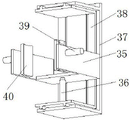
Further, still press from both sides and get mechanism I including getting, it installs on the slider of lead screw slip table I to press from both sides and get mechanism I including getting material frame, clamping frame, front and back regulation balladeur train, gets the lower extreme of material frame and fixes on the slider of lead screw slip table I, gets the upper end and the upper bracket sliding connection of material frame, adjust the balladeur train around and get material frame sliding connection, get the back of material frame and be provided with cylinder I that the drive front and back regulation balladeur train removed, clamping frame and front and back regulation balladeur train removal are connected, are provided with cylinder II on the front and back regulation balladeur train of clamping frame below, the flexible end and the clamping frame fixed connection of cylinder II are provided with cylinder III on the left and right sides face of clamping frame, and the inboard of clamping frame is worn to the flexible end of cylinder III, the flexible end of cylinder is connected with splint.
Further, still press from both sides and get mechanism II including pressing from both sides, press from both sides and get mechanism II the same with pressing from both sides the structure of getting mechanism I, lead screw slip table I and II parallel arrangement of lead screw slip table, lead screw slip table I drive press from both sides the direction of getting I removal of mechanism and lead screw slip table II drive press from both sides the opposite direction that gets II removals of mechanism.
Furthermore, the workpiece guide pillar is of a hollow structure, the upper end of the workpiece guide pillar is of a semicircular structure, the workpiece guide pillar is fixedly connected with the lower end of the fixed sleeve through a fixed plate, and a die hole corresponding to the punch is formed in the workpiece guide pillar.
The annular lifting support and the supporting sliding ring are sleeved on the workpiece guide pillar and are in sliding connection with the workpiece guide pillar, the supporting sliding ring is located above the annular lifting support, and the supporting sliding ring is connected with the annular lifting support through a connecting rib.
Furthermore, a bottom plate is arranged at the lower end of the supporting leg of the workbench, a box door is arranged on a scrap collecting box arranged on the bottom plate, a scrap groove is arranged inside the scrap collecting box, a sliding groove is arranged on the left side face of the scrap collecting box, an inlet at the upper end of the sliding groove corresponds to the lower end of a workpiece guide pillar, and the lower end of the sliding groove penetrates into the scrap collecting box and corresponds to the scrap groove.
Furthermore, a bottom support is arranged on the bottom plate, a cylinder IV is arranged on the bottom support, a telescopic end of the cylinder IV is fixedly connected with the annular lifting support, the annular lifting support can be driven to lift through the cylinder IV, then the supporting sliding ring is driven to lift, and the position of the workpiece is adjusted.
Furthermore, the clamping rotary seat further comprises a motor, an output shaft of the motor is connected with a driving wheel, a toothed ring is arranged on the lower portion of the clamping rotary seat, and the driving wheel is meshed with the toothed ring.
Furthermore, the jacking plate is of an arc-shaped structure, a through hole is formed in the jacking plate, the diameter of the through hole is larger than that of the punch, and the punch can freely penetrate through the through hole.
Compared with the prior art, the invention has the beneficial effects that:
1. the motor is arranged on the workpiece punching device, the clamping rotary seat is driven to rotate by the motor through the meshing of the driving wheel and the toothed ring, the clamping rotary seat can simultaneously drive the crank arm to rotate, the crank arm drives the sliding frame to slide on the guide rod, the workpiece is simultaneously fixed on the workpiece guide post from the side by the jacking plate, the workpiece is ensured to be firmly fixed, the punch on the punch rod is driven to move by the air cylinder V, the punch punches the workpiece, and residues punched by the punch fall into the workpiece guide post and freely fall under the action of gravity.
2. The workpiece clamping device is provided with the air cylinder III, the air cylinder III drives the two clamping plates to simultaneously move inwards to clamp a workpiece, the workpiece on the conveying mechanism is clamped through the clamping mechanism I, then the clamping mechanism I is driven to move through the lead screw sliding table I, the workpiece is conveyed to a position right above a workpiece guide pillar, then the workpiece is loosened, the lower end of the workpiece falls on the supporting sliding ring, then the lead screw sliding table I drives the clamping mechanism I to move to clamp the next workpiece, meanwhile, the lead screw sliding table II drives the clamping mechanism II to move to clamp the workpiece which is punched, the workpiece is conveyed to the other conveying mechanism, feeding and taking of the workpiece are completed through the clamping mechanism I and the clamping mechanism II, continuous operation can be achieved, and working efficiency is greatly improved.
3. The workpiece guide post is arranged on the punching machine, the workpiece guide post plays a role in supporting a workpiece, the punching quality is guaranteed, the workpiece can be conveniently inserted into the workpiece guide post due to the semicircular structure of the workpiece guide post, residues in the workpiece guide post fall into the chute and slide into the waste chute in the waste collection box, and the residues are collected in a centralized manner through the waste chute.
4. The support sliding ring is arranged on the pipe fitting, the lower end of the workpiece is supported by the support sliding ring, and the support sliding ring moves up and down simultaneously, so that the punching position of the workpiece can be adjusted, and the pipe fitting is convenient to adjust.
Drawings
FIG. 1 is a schematic structural view of the present invention;
FIG. 2 is a rear isometric view of the present invention;
FIG. 3 is a schematic view of the structure of the guiding mechanism of the present invention;
FIG. 4 is a schematic bottom view of the guide mechanism of the present invention;
FIG. 5 is a schematic view of the gripping mechanism of the present invention;
FIG. 6 is a cross-sectional view of the workpiece guide post of the present invention;
fig. 7 is a schematic view of the fixing cover structure of the present invention;
FIG. 8 is a schematic view of the waste collection box of the present invention.
In the figure: 1 workpiece guide post, 2 sliding chute, 3 bottom plate, 4 bottom bracket, 5 guiding mechanism, 6 scrap collecting box, 7 leading screw sliding table I, 8 upper supporting frame, 9 clamping mechanism I, 10 leading screw sliding table II, 11 clamping mechanism II, 12 workbench, 13 cylinder I, 14 box door, 15 cylinder IV, 16 annular lifting bracket, 17 fixing sleeve, 18 clamping rotary seat, 19 supporting sliding ring, 20 die hole, 21 through hole, 22 punch rod, 23 cylinder V, 24I-shaped bracket, 25 sliding frame, 26 crank arm, 27 clamping sleeve, 28 tightening plate, 29 supporting arm, 30 connecting rib, 31 motor, 32 driving wheel, 33 guiding rod, 34 toothed ring, 35 clamping frame, 36 cylinder II, 37 material taking frame, 38 front and back adjusting sliding frame, 39 cylinder III, 40 clamping plate, 41 punch, 42 waste chute and 43 fixing plate.
Detailed Description
The technical solutions in the embodiments of the present invention will be clearly and completely described below with reference to the drawings in the embodiments of the present invention, and it is obvious that the described embodiments are only a part of the embodiments of the present invention, and not all of the embodiments. All other embodiments, which can be derived by a person skilled in the art from the embodiments given herein without making any creative effort, shall fall within the protection scope of the present invention.
Referring to fig. 1-8, the present invention provides a technical solution: a punching device for processing automobile parts comprises a workpiece guide post 1, a workbench 12, a fixed sleeve 17, a clamping rotary base 18, an upper support frame 8, a guide mechanism 5 and a punching mechanism, wherein the fixed sleeve 17 is sleeved outside the workpiece guide post 1, the fixed sleeve 17 is fixed on the workbench 12, the workpiece guide post 1 is of a hollow structure, the upper end of the workpiece guide post 1 is of a semicircular structure, the workpiece guide post 1 is fixedly connected with the lower end of the fixed sleeve 17 through a fixed plate 43, a die hole 20 corresponding to a punch 41 is arranged on the workpiece guide post 1, the workpiece guide post 1 plays a role of backing a workpiece to ensure the punching quality, the semicircular structure of the workpiece guide post 1 is convenient for the workpiece to be inserted into the workpiece guide post 1, the punching device also comprises an annular lifting support frame 16 and a support sliding ring 19, the annular lifting support frame 16 and the support sliding ring 19 are sleeved on the workpiece guide post 1 and are in sliding connection with the workpiece guide post 1, the support sliding connection with the annular lifting support ring 19, the support sliding ring 19 is positioned above the annular lifting support frame 16, the support sliding ring 19 is connected with the annular lifting support frame 16 through a connecting rib 30, the lower end of the support sliding ring 19 is provided with a lifting cylinder, a waste collecting tank 6, the upper end of an upper end of a lifting cylinder 6 which is provided with a lifting cylinder 6, the upper end of a lifting cylinder 6 which is provided with a lifting cylinder, the lifting cylinder 6, the lifting cylinder 6 which is provided with a lifting cylinder 3, the position of a workpiece is adjusted, the lower end of a sliding chute 2 penetrates into a waste collection box 6 and corresponds to a waste chute 42, residues in a workpiece guide post 1 fall into the sliding chute 2 and slide into the waste chute 42 in the waste collection box 6, the residues are collected in a centralized manner through the waste chute 42, a clamping rotary seat 18 is sleeved on a fixed sleeve 17 and is rotatably connected with the fixed sleeve 17 through a bearing, a supporting arm 29 is arranged on the side surface of the clamping rotary seat 18, a guide mechanism 5 comprises a guide rod 33, a sliding frame 25 and a crank arm 26, one end of the guide rod 33 is fixedly connected with the fixed sleeve 17, the guide rod 33 is distributed around the center of the fixed sleeve 17, the sliding frame 25 is slidably connected with the guide rod 33, one end of the crank arm 26 is rotatably connected with the supporting arm 29, the other end of the crank arm 26 is rotatably connected with the sliding frame 25, the electric motor 31 is further included, and an output shaft of the electric motor 31 is connected with a driving wheel 32, the lower part of the clamping rotary seat 18 is provided with a toothed ring 34, a driving wheel 32 is meshed with the toothed ring 34, the clamping rotary seat 18 can simultaneously drive a crank arm 26 to rotate when rotating, the crank arm 26 drives a sliding frame 25 to slide on a guide rod 33, a jacking plate 28 can simultaneously fix a workpiece on a workpiece guide post 1 from the side surface, so that the workpiece is firmly fixed, the jacking plate 28 is of an arc-shaped structure, a through hole 21 is formed in the jacking plate 28, the diameter of the through hole 21 is larger than that of a punch 41, the punch 41 can freely pass through the through hole 21, the punching mechanism comprises an I-shaped bracket 24, a cylinder V23 and a clamping sleeve 27, the lower end of the I-shaped bracket 24 is fixed on the sliding frame 25, the cylinder V23 and the clamping sleeve 27 are fixed on the I-shaped bracket 24, the telescopic end of the cylinder V23 is connected with a punch rod 22, the punch rod 22 passes through the clamping sleeve 27, the other end of the punch rod 22 is connected with the punch 41, the punch 41 on the punch rod 22 is driven to move by the cylinder V23, the punch 41 punches a hole in the workpiece, residues punched by the punch 41 fall into the workpiece guide pillar 1 and fall freely under the action of gravity, the upper support frame 8 is arranged on the workbench 12, the upper support frame 8 is provided with a lead screw sliding table I7 and a lead screw sliding table II 10, and the end parts of the lead screw sliding table I7 and the lead screw sliding table II 10 are respectively provided with a driving motor.
The automatic feeding device also comprises a clamping mechanism I9, the clamping mechanism I9 is installed on a sliding block of the screw rod sliding table I7, the clamping mechanism I9 comprises a material taking frame 37, a clamping frame 35 and a front and back adjusting sliding frame 38, the lower end of the material taking frame 37 is fixed on the sliding block of the screw rod sliding table I7, the upper end of the material taking frame 37 is in sliding connection with the upper supporting frame 8, the front and back adjusting sliding frame 38 is in sliding connection with the material taking frame 37, a cylinder I13 for driving the front and back adjusting sliding frame 38 to move is arranged on the back of the material taking frame 37, the clamping frame 35 is in moving connection with the front and back adjusting sliding frame 38, a cylinder II 36 is arranged on the front and back adjusting sliding frame 38 below the clamping frame 35, the telescopic end of the cylinder II 36 is fixedly connected with the clamping frame 35, the front and back adjusting sliding frame 38 is integrally adjusted front and back through the cylinder I13, so that the position of the clamping frame 35 corresponds to the position of a workpiece, the adjustment is convenient, the clamping frame 35 can be driven to move up and down through the cylinder II 36, further driving the workpiece on the clamping frame 35 to move, wherein the left side surface and the right side surface of the clamping frame 35 are provided with air cylinders III 39, the telescopic ends of the air cylinders III 39 penetrate into the clamping frame 35, the telescopic ends of the air cylinders III 39 are connected with clamping plates 40, the two clamping plates 40 are driven by the air cylinders III 39 to simultaneously move inwards to clamp the workpiece, the clamping mechanism II 11 is further included, the clamping mechanism II 11 and the clamping mechanism I9 are identical in structure, the screw sliding table I7 and the screw sliding table II 10 are arranged in parallel, the direction in which the screw sliding table I7 drives the clamping mechanism I9 to move is opposite to the direction in which the screw sliding table II 10 drives the clamping mechanism II 11 to move, the clamping mechanism I9 clamps the workpiece on the conveying mechanism, then the screw sliding table I7 drives the clamping mechanism I9 to move, the workpiece is conveyed to the position right above the workpiece guide pillar 1, then the workpiece is loosened, and the lower end of the workpiece falls on the supporting sliding ring 19, the automatic punching device comprises a screw rod sliding table I7, a clamping mechanism I9, a feeding mechanism I9, a clamping mechanism II 11, a conveying mechanism II 10, a clamping mechanism II 11, a conveying mechanism II, a side punching mode, a plurality of punching holes of the pipe fitting at one time, automatic collection of residues, continuous feeding and material taking of the pipe fitting, and the like.
When in use: the workpiece on the conveying mechanism is clamped by the clamping mechanism I9, then the clamping mechanism I9 is driven to move by the lead screw sliding table I7, the workpiece is conveyed to the position right above the workpiece guide post 1, the clamping frame 35 can be driven to move downwards by the air cylinder II 36, the lower end of the workpiece is inserted into the workpiece guide post 1, the air cylinder III 39 drives the two clamping plates 40 to move towards two sides to loosen the workpiece, the lower end of the workpiece falls on the supporting sliding ring 19, then the lead screw sliding table I7 drives the clamping mechanism I9 to move to clamp the next workpiece, the motor 31 is meshed with the gear ring 34 through the driving wheel 32 to drive the clamping rotary seat 18 to rotate, the clamping rotary seat 18 can simultaneously drive the crank arm 26 to rotate, the crank arm 26 drives the sliding frame 25 to slide on the guide rod 33, and the jacking plate 28 fixes the workpiece on the workpiece guide post 1 from the side surface at the same time, drive drift 41 on the jumper bar 22 through cylinder V23 and remove, drift 41 punches a hole to the work piece, accomplish the back that punches a hole, lead screw slip table II 10 drives to press from both sides and gets mechanism II 11 and removes the work piece of pressing from both sides the completion and punching a hole, deliver to on another conveyor, get mechanism I9 and press from both sides and get mechanism II 11 and accomplish the pay-off to the work piece and get the material work through pressing from both sides, can realize the continuity of operation, the work efficiency is greatly improved, adjust around adjusting balladeur train 38 wholly through cylinder I13, thereby guarantee that the position of clamping frame 35 corresponds with the position of work piece, it is convenient to adjust, the residue falls in chute 2 in work piece guide pillar 1, and the landing is in the dirty tank 42 in garbage collection box 6, concentrate the collection to the residue through dirty tank 42.
Although embodiments of the present invention have been shown and described, it will be appreciated by those skilled in the art that various changes, modifications, substitutions and alterations can be made in these embodiments without departing from the principles and spirit of the invention, the scope of which is defined in the appended claims and their equivalents.
Claims (9)
1. The utility model provides a punching device of automobile parts processing usefulness, includes work piece guide pillar (1), workstation (12), fixed cover (17), presss from both sides tight roating seat (18), upper bracket frame (8), guiding mechanism (5) and the mechanism of punching a hole, its characterized in that: the punching mechanism comprises an I-shaped support (24), a cylinder V (23) and a clamping sleeve (27), the lower end of the I-shaped support (24) is fixed on a support frame (25), the cylinder V (23) and the clamping sleeve (27) are fixed on the I-shaped support (24), the punching mechanism comprises a punch pin (22) and a punch pin (22), the other end of the punch pin (22) is connected with a punch rod (8) in the punch table (12), the clamping rotary seat (18) is sleeved on the fixed sleeve (17) and is rotationally connected with the fixed sleeve (17) through a bearing, a support arm (29) is arranged on the side face of the clamping rotary seat (18), the guide mechanism (5) comprises a guide rod (33), a sliding frame (25) and a crank arm (26), one end of the guide rod (33) is fixedly connected with the fixed sleeve (17), the guide rod (33) is distributed around the center of the fixed sleeve (17), the sliding frame (25) is slidably connected with the guide rod (33), one end of the support arm (26) is rotationally connected with the support arm (29), the other end of the crank arm (26) is rotationally connected with the sliding frame (25), the punching mechanism comprises an I-shaped support (24), the cylinder V (23) and the clamping sleeve (27), the punch pin (22) is connected with the punch pin (22) arranged in the punch pin (22) and is connected with the punch pin (41) in the punch pin (22) in the punch table (22), and a screw rod sliding table I (7) and a screw rod sliding table II (10) are arranged on the upper support frame (8).
2. The punching device for processing the automobile parts according to claim 1, wherein: still including pressing from both sides and getting mechanism I (9), press from both sides and get mechanism I (9) and install on the slider of lead screw slip table I (7), press from both sides and get mechanism I (9) including getting material frame (37), clamping frame (35), front and back regulation balladeur train (38), get the lower extreme of material frame (37) and fix on the slider of lead screw slip table I (7), get the upper end and the upper support frame (8) sliding connection of material frame (37), adjust balladeur train (38) and get material frame (37) sliding connection around, the back of getting material frame (37) is provided with the cylinder I (13) that drive front and back regulation balladeur train (38) removed, clamping frame (35) and front and back regulation balladeur train (38) moving connection are provided with cylinder II (36) on front and back regulation balladeur train (38) of clamping frame (35) below, the flexible end and clamping frame (35) fixed connection of cylinder II (36), be provided with cylinder (39) on the left and right sides face of clamping frame (35), the flexible end of cylinder (39) wears to the inboard of clamping frame (35), the flexible end of cylinder (39) is connected with splint (40).
3. The punching device for processing the automobile parts according to claim 1, wherein: still press from both sides and get mechanism II (11), press from both sides and get mechanism II (11) and press from both sides the same with the structure of getting mechanism I (9), lead screw slip table I (7) and lead screw slip table II (10) parallel arrangement, lead screw slip table I (7) drive to press from both sides the direction of getting mechanism I (9) and moving and press from both sides the opposite direction of getting mechanism II (11) and moving with lead screw slip table II (10) drive.
4. The punching device for processing the automobile parts according to claim 1, wherein: the workpiece guide pillar (1) is of a hollow structure, the upper end of the workpiece guide pillar (1) is of a semicircular structure, the workpiece guide pillar (1) is fixedly connected with the lower end of the fixed sleeve (17) through a fixed plate (43), and a die hole (20) corresponding to the punch (41) is formed in the workpiece guide pillar (1).
5. The punching device for processing the automobile parts according to claim 1, wherein: the workpiece guide post structure is characterized by further comprising an annular lifting support (16) and a supporting sliding ring (19), the annular lifting support (16) and the supporting sliding ring (19) are sleeved on the workpiece guide post (1) and are in sliding connection with the workpiece guide post (1), the supporting sliding ring (19) is located above the annular lifting support (16), and the supporting sliding ring (19) is connected with the annular lifting support (16) through a connecting rib (30).
6. The punching device for processing the automobile parts according to claim 5, wherein: the support leg lower extreme of workstation (12) is provided with bottom plate (3), is provided with chamber door (14) on being provided with scrap collecting box (6) on bottom plate (3), the inside of scrap collecting box (6) is provided with dirty tank (42), be provided with on the left surface of scrap collecting box (6) smooth silo (2), the entry of smooth silo (2) upper end is corresponding with the lower extreme of work piece guide pillar (1), the lower extreme of smooth silo (2) is worn to waste collecting box (6) and is corresponding with dirty tank (42).
7. The punching device for processing the automobile parts according to claim 6, wherein: the bottom plate (3) is provided with a bottom support (4), the bottom support (4) is provided with an air cylinder IV (15), and the telescopic end of the air cylinder IV (15) is fixedly connected with an annular lifting support (16).
8. The punching device for processing the automobile parts according to claim 1, wherein: the clamping rotating seat is characterized by further comprising a motor (31), an output shaft of the motor (31) is connected with a driving wheel (32), a toothed ring (34) is arranged on the lower portion of the clamping rotating seat (18), and the driving wheel (32) is meshed with the toothed ring (34).
9. The punching device for processing the automobile parts according to claim 1, wherein: the puller plate (28) is of an arc-shaped structure, a through hole (21) is formed in the puller plate (28), the diameter of the through hole (21) is larger than that of the punch (41), and the punch (41) can freely penetrate through the through hole (21).
Priority Applications (1)
| Application Number | Priority Date | Filing Date | Title |
|---|---|---|---|
| CN202211380119.7A CN115635000A (en) | 2022-11-05 | 2022-11-05 | Punching device for machining automobile parts |
Applications Claiming Priority (1)
| Application Number | Priority Date | Filing Date | Title |
|---|---|---|---|
| CN202211380119.7A CN115635000A (en) | 2022-11-05 | 2022-11-05 | Punching device for machining automobile parts |
Publications (1)
| Publication Number | Publication Date |
|---|---|
| CN115635000A true CN115635000A (en) | 2023-01-24 |
Family
ID=84947857
Family Applications (1)
| Application Number | Title | Priority Date | Filing Date |
|---|---|---|---|
| CN202211380119.7A Withdrawn CN115635000A (en) | 2022-11-05 | 2022-11-05 | Punching device for machining automobile parts |
Country Status (1)
| Country | Link |
|---|---|
| CN (1) | CN115635000A (en) |
Cited By (2)
| Publication number | Priority date | Publication date | Assignee | Title |
|---|---|---|---|---|
| CN116586505A (en) * | 2023-07-19 | 2023-08-15 | 雅安成建工业化建筑有限公司 | Punching device for mounting steel structure beam column |
| CN117046953A (en) * | 2023-08-11 | 2023-11-14 | 南皮县伟达五金制造有限公司 | Pneumatic punching machine capable of adjusting punch direction |
-
2022
- 2022-11-05 CN CN202211380119.7A patent/CN115635000A/en not_active Withdrawn
Cited By (4)
| Publication number | Priority date | Publication date | Assignee | Title |
|---|---|---|---|---|
| CN116586505A (en) * | 2023-07-19 | 2023-08-15 | 雅安成建工业化建筑有限公司 | Punching device for mounting steel structure beam column |
| CN116586505B (en) * | 2023-07-19 | 2023-10-03 | 雅安成建工业化建筑有限公司 | Punching device for mounting steel structure beam column |
| CN117046953A (en) * | 2023-08-11 | 2023-11-14 | 南皮县伟达五金制造有限公司 | Pneumatic punching machine capable of adjusting punch direction |
| CN117046953B (en) * | 2023-08-11 | 2024-01-26 | 南皮县伟达五金制造有限公司 | Pneumatic punching machine capable of adjusting punch direction |
Similar Documents
| Publication | Publication Date | Title |
|---|---|---|
| CN110369606B (en) | Automatic punching machine for hardware pipes | |
| CN115635000A (en) | Punching device for machining automobile parts | |
| CN212419293U (en) | C-shaped steel clamping, positioning and punching equipment in photovoltaic support | |
| CN210789980U (en) | Sawing machine with high cutting efficiency | |
| CN216502715U (en) | Cutting equipment of pipe cutting machine for machining carrier roller | |
| CN212419303U (en) | Efficient punching equipment for machining | |
| CN110465590A (en) | A kind of automatic stamping mold | |
| CN216324400U (en) | Flanging machine of automatic tensioning device | |
| CN211361444U (en) | Clamping device for machining special-shaped riser | |
| CN210817582U (en) | Novel bench drilling machine for producing transformer | |
| CN209598667U (en) | A kind of cutting oil pressure combined machine | |
| CN220659407U (en) | Milling machine for processing section of aluminum alloy door and window | |
| CN216911861U (en) | Bending device for sheet metal machining | |
| CN213613618U (en) | Hole punching device for irregular hole sites for power transmission iron tower | |
| CN220739283U (en) | Multifunctional punching equipment | |
| CN216226421U (en) | Punching device for machining mechanical parts | |
| CN216938704U (en) | Punching and shearing device for processing metal parts | |
| CN213701402U (en) | High-efficient automatic molding machine | |
| CN219541408U (en) | Full-automatic pipe bending machine with keep off material frock | |
| CN215880410U (en) | Flexible brain electrode processing is with former material cutting equipment | |
| CN214639567U (en) | Special machine for forming steel toe cap | |
| CN212419285U (en) | Punching device for processing C-shaped steel for photovoltaic anti-seismic support | |
| CN210045888U (en) | Automatic feeding device for stamping and grinding tool | |
| CN214081831U (en) | Automatic secondary cutting system of control | |
| CN220161127U (en) | Stamping mechanism convenient for demolding |
Legal Events
| Date | Code | Title | Description |
|---|---|---|---|
| PB01 | Publication | ||
| PB01 | Publication | ||
| SE01 | Entry into force of request for substantive examination | ||
| SE01 | Entry into force of request for substantive examination | ||
| WW01 | Invention patent application withdrawn after publication | ||
| WW01 | Invention patent application withdrawn after publication |
Application publication date: 20230124 |